US4046280A - Direct mounting reverse buckling disc - Google Patents
Direct mounting reverse buckling disc Download PDFInfo
- Publication number
- US4046280A US4046280A US05/702,734 US70273476A US4046280A US 4046280 A US4046280 A US 4046280A US 70273476 A US70273476 A US 70273476A US 4046280 A US4046280 A US 4046280A
- Authority
- US
- United States
- Prior art keywords
- centering ring
- flange portion
- disc
- flange
- flanges
- Prior art date
- Legal status (The legal status is an assumption and is not a legal conclusion. Google has not performed a legal analysis and makes no representation as to the accuracy of the status listed.)
- Expired - Lifetime
Links
Images
Classifications
-
- F—MECHANICAL ENGINEERING; LIGHTING; HEATING; WEAPONS; BLASTING
- F16—ENGINEERING ELEMENTS AND UNITS; GENERAL MEASURES FOR PRODUCING AND MAINTAINING EFFECTIVE FUNCTIONING OF MACHINES OR INSTALLATIONS; THERMAL INSULATION IN GENERAL
- F16K—VALVES; TAPS; COCKS; ACTUATING-FLOATS; DEVICES FOR VENTING OR AERATING
- F16K17/00—Safety valves; Equalising valves, e.g. pressure relief valves
- F16K17/02—Safety valves; Equalising valves, e.g. pressure relief valves opening on surplus pressure on one side; closing on insufficient pressure on one side
- F16K17/14—Safety valves; Equalising valves, e.g. pressure relief valves opening on surplus pressure on one side; closing on insufficient pressure on one side with fracturing member
- F16K17/16—Safety valves; Equalising valves, e.g. pressure relief valves opening on surplus pressure on one side; closing on insufficient pressure on one side with fracturing member with fracturing diaphragm ; Rupture discs
- F16K17/1606—Safety valves; Equalising valves, e.g. pressure relief valves opening on surplus pressure on one side; closing on insufficient pressure on one side with fracturing member with fracturing diaphragm ; Rupture discs of the reverse-buckling-type
- F16K17/1613—Safety valves; Equalising valves, e.g. pressure relief valves opening on surplus pressure on one side; closing on insufficient pressure on one side with fracturing member with fracturing diaphragm ; Rupture discs of the reverse-buckling-type with additional cutting means
-
- F—MECHANICAL ENGINEERING; LIGHTING; HEATING; WEAPONS; BLASTING
- F16—ENGINEERING ELEMENTS AND UNITS; GENERAL MEASURES FOR PRODUCING AND MAINTAINING EFFECTIVE FUNCTIONING OF MACHINES OR INSTALLATIONS; THERMAL INSULATION IN GENERAL
- F16K—VALVES; TAPS; COCKS; ACTUATING-FLOATS; DEVICES FOR VENTING OR AERATING
- F16K17/00—Safety valves; Equalising valves, e.g. pressure relief valves
- F16K17/40—Safety valves; Equalising valves, e.g. pressure relief valves with a fracturing member, e.g. fracturing diaphragm, glass, fusible joint
-
- Y—GENERAL TAGGING OF NEW TECHNOLOGICAL DEVELOPMENTS; GENERAL TAGGING OF CROSS-SECTIONAL TECHNOLOGIES SPANNING OVER SEVERAL SECTIONS OF THE IPC; TECHNICAL SUBJECTS COVERED BY FORMER USPC CROSS-REFERENCE ART COLLECTIONS [XRACs] AND DIGESTS
- Y10—TECHNICAL SUBJECTS COVERED BY FORMER USPC
- Y10T—TECHNICAL SUBJECTS COVERED BY FORMER US CLASSIFICATION
- Y10T137/00—Fluid handling
- Y10T137/1624—Destructible or deformable element controlled
- Y10T137/1632—Destructible element
- Y10T137/1692—Rupture disc
- Y10T137/1714—Direct pressure causes disc to burst
- Y10T137/1729—Dome shape
- Y10T137/1737—Reverse buckling
-
- Y—GENERAL TAGGING OF NEW TECHNOLOGICAL DEVELOPMENTS; GENERAL TAGGING OF CROSS-SECTIONAL TECHNOLOGIES SPANNING OVER SEVERAL SECTIONS OF THE IPC; TECHNICAL SUBJECTS COVERED BY FORMER USPC CROSS-REFERENCE ART COLLECTIONS [XRACs] AND DIGESTS
- Y10—TECHNICAL SUBJECTS COVERED BY FORMER USPC
- Y10T—TECHNICAL SUBJECTS COVERED BY FORMER US CLASSIFICATION
- Y10T137/00—Fluid handling
- Y10T137/1624—Destructible or deformable element controlled
- Y10T137/1632—Destructible element
- Y10T137/1692—Rupture disc
- Y10T137/1759—Knife or cutter causes disc to break
Definitions
- This invention relates to safety pressure release devices, and more particularly to improvements in structures for mounting reverse buckling rupture discs and associated elements.
- Reverse buckling rupture discs have found increasing use as precision pressure relief devices which permit working pressures very close to rated rupture pressures.
- Such devices ordinarily comprise a diaphragm, usually a relatively thin metal, which is centrally bulged and positioned in a pressure relief passageway with the convex surface of the bulge directed toward the higher pressure.
- a sharp puncturing element usually in the form of a knife-blade, is often located near the concave surface of the bulge so that upon disc buckling, the collapsing metal is cut.
- seating rings were used in contact with the disc flange, usually on both sides thereof but, at least on the higher pressure side, to insure extensive and precision contact in an attempt to avoid a possible distortion of the disc flange during the tightening of mounting bolts which could affect collapse pressure of the disc. It has now been discovered that such separate seating rings also may be completely eliminated and, instead, reliance for supporting the disc flange placed solely on mounting flanges forming a part of associated elements. Specifically, the flange forming part of the centering ring supporting the knife-blade and the flange associated with a centering ring projecting toward the higher pressure side of the disc produce the entire disc flange contacting support. The latter centering ring also forms an excellent mounting structure for a protective device, such as a screen extending across the circular opening thereof, to provide protection against accidental contact with the disc dome which tends to adversely affect rated collapse pressure.
- a protective device such as a screen extending across the circular opening thereof, to provide protection against accidental contact with the disc dome which tend
- reverse buckling discs are adapted for mounting, with a puncturing element and protective element, directly between ASA type flanges without the need for disc base and holddown flanges or separate seating rings.
- the principal objects of the present invention are: to provide a reverse buckling disc and puncturing element assembly adapted for mounting directly between ANSI type flanges; to provide such an assembly which eliminates the need for disc base and disc holddown flanges; to provide such an assembly which further eliminates the need for separate disc flange seating rings; to provide such a reverse disc arrangement wherein the disc dome is protected against accidental contact which could adversely affect rated collapse pressure; to provide such a reverse disc arrangement which may be quickly placed or replaced into operation without the need for highly skilled personnel; to provide such an arrangement wherein proper seating of the disc is easily obtained for accurate operation whether mounted first on the inlet or outlet pipe flange; to provide such an arrangement wherein proper seating of the disc is easily obtained in difficult locations; and to provide such an arrangement which is relatively inexpensive and yet highly reliable in use.
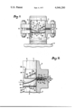
- FIG. 1 is a fragmentary cross-sectional view showing a set of ANSI type flanges with a reverse buckling disc arrangement embodying this invention assembled directly therewith in absence of separate seating rings, a portion being broken away to better show the cooperative relationship.
- FIG. 2 is a fragmentary, cross-sectional, detailed view on an enlarged scale for depicting the relationship of the parts of FIG. 1.
- the reference numeral 1 generally indicates a safety pressure relief device embodying this invention.
- the device 1 is shown mounted directly between a pair, or set, of ANSI type flanges, in this example, lower flange 2 and upper flange 3 which are respectively characterized by bodies forming opposed, flat annular faces 4 and 5 surrounding coaxially aligned lower and upper cylindrical bores 6 and 7.
- a plurality of bolts 8 extend in a conventional circular pattern through the flanges 2 and 3, drawing the respective flange faces 4 and 5 toward contacting relation.
- the device 1 in operation, normally blocks flow out of a pressure relief passageway 9 formed by the upper bore 7.
- the device 1 includes, in this example, a rupture disc 12 having a central bulged portion 13 projecting into the passageway 10 and an integral, flat rim or flange portion 14 adapted to extend radially between the flange faces 4 and 5.
- a disc puncturing unit 18 comprises a pair of knife-blades 19 having cutting edges 20 directed toward the concave side of the disc bulged portion 13 and sloping toward a central sharp point 21.
- the knife-blades 19, in this example, are welded at the ends thereof to the inside cylindrical surface 22 of a centering ring 23, but other mounting arrangements are also contemplated.
- the centering ring 23 is composed of a cylindrical tubular wall portion 24, forming the surface 22, and an integral, flat rim or flange portion 25.
- the flange portion 25 projects radially along the upper surface 26 of the disc flange 14 and, in this example, is secured thereto at 27, for example by a circular pattern of spot-welds, although other securing procedures such as a continuous weld or strong adhesive are useful and tend to assure zero leakage therebetween where this is a problem.
- the wall portion 24 of the centering ring 23 projects downstream or away from the high pressure side of the disc, and, therefore, in mounting the device 1 between the flanges 2 and 3, the tubular wall portion 24 is telescoped into the cylindrical bore 7 after placing a suitable sealing gasket 28 between the centering ring flange portion 25 and the flange face 5.
- a disc protective unit 35 comprises a centering ring 36 composed of a cylindrical tubular wall portion 37 and an integral, flat rim or flange portion 38.
- the flange portion 38 projects radially along the other surface 39 of the disc flange 14 and, in this example, is secured thereto at 40, for example, by a circular pattern of spot-welds, although other means may be used for leakage control or other reasons, as at 27.
- a bite 41 is formed in the flange 38 and bulges slightly toward the disc flange 14, engaging and somewhat deforming the flange 14 along the entire circular extent thereof to also aid in eliminating the possibility of leakage between the flanges 14 and 38.
- the tubular wall portion 37 of the centering ring 36 is telescoped into the cylindrical bore 6 after placing a suitable sealing gasket 42 between a centering ring flange portion 38 and the inlet flange face 4.
- centering ring 35 provides an excellent seat 43 for mounting a screen 44 which serves to protect the dome of the disc 12 against accidental denting which would adversely affect the rated collapse pressure.
- the screen 44 is selected in accordance with particular requirements to provide sufficient physical protection while also allowing ample flowthrough relief after disc rupture.
Abstract
A reverse buckling disc arrangement for direct mounting eliminates separate inlet and outlet seating rings for the disc flange. Centering ring units on both sides of the disc have flanges doubling as the seating rings. The centering ring projecting toward the higher pressure supports a screen for protecting the disc dome while permitting necessary flow-through.
Description
This invention relates to safety pressure release devices, and more particularly to improvements in structures for mounting reverse buckling rupture discs and associated elements.
Reverse buckling rupture discs have found increasing use as precision pressure relief devices which permit working pressures very close to rated rupture pressures. Such devices ordinarily comprise a diaphragm, usually a relatively thin metal, which is centrally bulged and positioned in a pressure relief passageway with the convex surface of the bulge directed toward the higher pressure. To insure rupture when the rated pressure differential is exceeded, a sharp puncturing element, usually in the form of a knife-blade, is often located near the concave surface of the bulge so that upon disc buckling, the collapsing metal is cut.
Heretofore, a common method of mounting such discs and puncturing elements was by insertion between standard ANSI (American National Standards Institute) pipe flanges with the aid of precision base and holddown flanges which sandwiched the disc flange therebetween to insure proper seating. Usually, the puncturing element was welded or otherwise secured to the holddown flange in position for cutting the disc upon reversal. Recent improvements in such arrangements involve mounting the reverse buckling disc together with a puncturing element directly between ANSI type flanges. For example, see U.S. Pat. No. 3,834,581 wherein pre-seated bulged discs are preassembled with a centering ring unit containing a puncturing element and whereby the centering ring unit operably positions both the preseated disc and the puncturing element between the flanges, eliminating the need for precision disc base and disc holddown flanges.
In the practice of the invention described in U.S Pat. No. 3,834,581, seating rings were used in contact with the disc flange, usually on both sides thereof but, at least on the higher pressure side, to insure extensive and precision contact in an attempt to avoid a possible distortion of the disc flange during the tightening of mounting bolts which could affect collapse pressure of the disc. It has now been discovered that such separate seating rings also may be completely eliminated and, instead, reliance for supporting the disc flange placed solely on mounting flanges forming a part of associated elements. Specifically, the flange forming part of the centering ring supporting the knife-blade and the flange associated with a centering ring projecting toward the higher pressure side of the disc produce the entire disc flange contacting support. The latter centering ring also forms an excellent mounting structure for a protective device, such as a screen extending across the circular opening thereof, to provide protection against accidental contact with the disc dome which tends to adversely affect rated collapse pressure.
In the practice of this invention, reverse buckling discs are adapted for mounting, with a puncturing element and protective element, directly between ASA type flanges without the need for disc base and holddown flanges or separate seating rings.
The principal objects of the present invention are: to provide a reverse buckling disc and puncturing element assembly adapted for mounting directly between ANSI type flanges; to provide such an assembly which eliminates the need for disc base and disc holddown flanges; to provide such an assembly which further eliminates the need for separate disc flange seating rings; to provide such a reverse disc arrangement wherein the disc dome is protected against accidental contact which could adversely affect rated collapse pressure; to provide such a reverse disc arrangement which may be quickly placed or replaced into operation without the need for highly skilled personnel; to provide such an arrangement wherein proper seating of the disc is easily obtained for accurate operation whether mounted first on the inlet or outlet pipe flange; to provide such an arrangement wherein proper seating of the disc is easily obtained in difficult locations; and to provide such an arrangement which is relatively inexpensive and yet highly reliable in use.
Other objects and advantages of this invention will become apparent from the following description taken in connection with the accompanying drawings wherein are set forth, by way of illustration and example, certain embodiments of this invention.
The drawings constitute a part of the specification and include an exemplary embodiment of the present invention and illustrate various objects and features of the direct mounting disc arrangement.
FIG. 1 is a fragmentary cross-sectional view showing a set of ANSI type flanges with a reverse buckling disc arrangement embodying this invention assembled directly therewith in absence of separate seating rings, a portion being broken away to better show the cooperative relationship.
FIG. 2 is a fragmentary, cross-sectional, detailed view on an enlarged scale for depicting the relationship of the parts of FIG. 1.
Referring to the drawings in more detail:
The reference numeral 1 generally indicates a safety pressure relief device embodying this invention. The device 1 is shown mounted directly between a pair, or set, of ANSI type flanges, in this example, lower flange 2 and upper flange 3 which are respectively characterized by bodies forming opposed, flat annular faces 4 and 5 surrounding coaxially aligned lower and upper cylindrical bores 6 and 7. A plurality of bolts 8 extend in a conventional circular pattern through the flanges 2 and 3, drawing the respective flange faces 4 and 5 toward contacting relation.
The device 1, in operation, normally blocks flow out of a pressure relief passageway 9 formed by the upper bore 7. The passageway 9, upon actuation of the device 1, forms a continuation of a passageway 10 formed by the lower bore 6 which communicates with a pressure vessel 11 of any suitable configuration.
The device 1 includes, in this example, a rupture disc 12 having a central bulged portion 13 projecting into the passageway 10 and an integral, flat rim or flange portion 14 adapted to extend radially between the flange faces 4 and 5. In the structure of FIGS. 1 and 2, a disc puncturing unit 18 comprises a pair of knife-blades 19 having cutting edges 20 directed toward the concave side of the disc bulged portion 13 and sloping toward a central sharp point 21. The knife-blades 19, in this example, are welded at the ends thereof to the inside cylindrical surface 22 of a centering ring 23, but other mounting arrangements are also contemplated. The centering ring 23 is composed of a cylindrical tubular wall portion 24, forming the surface 22, and an integral, flat rim or flange portion 25. The flange portion 25 projects radially along the upper surface 26 of the disc flange 14 and, in this example, is secured thereto at 27, for example by a circular pattern of spot-welds, although other securing procedures such as a continuous weld or strong adhesive are useful and tend to assure zero leakage therebetween where this is a problem.
The wall portion 24 of the centering ring 23 projects downstream or away from the high pressure side of the disc, and, therefore, in mounting the device 1 between the flanges 2 and 3, the tubular wall portion 24 is telescoped into the cylindrical bore 7 after placing a suitable sealing gasket 28 between the centering ring flange portion 25 and the flange face 5.
A disc protective unit 35 comprises a centering ring 36 composed of a cylindrical tubular wall portion 37 and an integral, flat rim or flange portion 38. The flange portion 38 projects radially along the other surface 39 of the disc flange 14 and, in this example, is secured thereto at 40, for example, by a circular pattern of spot-welds, although other means may be used for leakage control or other reasons, as at 27. Preferably a bite 41 is formed in the flange 38 and bulges slightly toward the disc flange 14, engaging and somewhat deforming the flange 14 along the entire circular extent thereof to also aid in eliminating the possibility of leakage between the flanges 14 and 38.
In mounting the device, the tubular wall portion 37 of the centering ring 36 is telescoped into the cylindrical bore 6 after placing a suitable sealing gasket 42 between a centering ring flange portion 38 and the inlet flange face 4.
With the structure above described, it is essentially immaterial whether the disc assembly is mounted first in the outlet pipe flange 3 or inlet pipe flange 2, the installer being free to select whichever is most convenient under the particular circumstances. Also, separate seating rings are eliminated, thereby substantially reducing cost while providing the advantage of centering structure projecting both axial directions from the disc 12.
In addition, the centering ring 35 provides an excellent seat 43 for mounting a screen 44 which serves to protect the dome of the disc 12 against accidental denting which would adversely affect the rated collapse pressure. The screen 44 is selected in accordance with particular requirements to provide sufficient physical protection while also allowing ample flowthrough relief after disc rupture.
It is to be understood that while certain forms of this invention have been illustrated and described, it is not to be limited to the specific arrangement of parts herein described and shown except insofar as limitations are included in the following claims.
Claims (6)
1. In combination, an inlet pipe flange and an outlet pipe flange and a safety pressure relief device mounted directly between said flanges:
a. said inlet and outlet flanges respectively having radially projecting opposed, flat annular clamping faces, said inlet and outlet flanges each having a bore extending through said flange to said clamping face,
b. said relief device comprising a rupture disc arrangement having a flange portion extending therefrom, said rupture disc arrangement being of the reverse buckling type having a bulged central portion with a convex side,
c. a first centering ring comprising a tubular wall portion and a flange portion, and puncturing means mounted at least partially within said first centering ring tubular wall portion, said bulged central portion being directed away from said puncturing means,
d. said first centering ring tubular wall portion being telescopically received into said outlet bore,
e. means cooperating between said first centering ring flange portion and disc arrangement flange portion whereby said last named flange portions are radially coaxially retained with respect to each other in absence of said pipe flanges,
f. a second centering ring comprising a tubular wall portion surrounding said bulged central portion and a flange portion, said second centering ring tubular wall portion forming a mouth and being telescopically received into said inlet bore, means cooperating between said second centering ring flange portion and disc flange portion whereby said last named flange portions are radially coaxially retained with respect to each other in absence of said pipe flanges, and
g. means clamping said first and second centering ring flange portions and rupture disc flange portion in sandwiched arrangement between said pipe flanges.
2. The combination as set forth in claim 1 including:
a. a circular bite in said second centering ring flange portion and engaging said disc flange.
3. The combination as set forth in claim 1 wherein said first centering ring flange portion and said disc flange portion and said second centering ring flange portion are fixed with respect to each other by means of spot-welds.
4. The combination as set forth in claim 1 wherein said first centering ring flange portion and said disc flange portion and said second centering ring flange portion are fixed with respect to each other by means of continuous welds.
5. The combination as set forth in claim 1 wherein said first centering ring flange portion and said disc flange portion and said second centering ring flange portion are fixed with respect to each other by means of adhesive.
6. The combination as set forth in claim 1 wherein:
a. a protective flow-through member is mounted on said second centering ring and extends across said mouth in spaced relation to said convex side of said bulged central portion.
Priority Applications (3)
| Application Number | Priority Date | Filing Date | Title |
|---|---|---|---|
| US05/702,734 US4046280A (en) | 1976-07-06 | 1976-07-06 | Direct mounting reverse buckling disc |
| CA278,639A CA1054022A (en) | 1976-07-06 | 1977-05-17 | Direct mounting reverse buckling disc |
| IE1169/77A IE44967B1 (en) | 1976-07-06 | 1977-06-08 | Improved safety pressure relief device |
Applications Claiming Priority (1)
| Application Number | Priority Date | Filing Date | Title |
|---|---|---|---|
| US05/702,734 US4046280A (en) | 1976-07-06 | 1976-07-06 | Direct mounting reverse buckling disc |
Publications (1)
| Publication Number | Publication Date |
|---|---|
| US4046280A true US4046280A (en) | 1977-09-06 |
Family
ID=24822378
Family Applications (1)
| Application Number | Title | Priority Date | Filing Date |
|---|---|---|---|
| US05/702,734 Expired - Lifetime US4046280A (en) | 1976-07-06 | 1976-07-06 | Direct mounting reverse buckling disc |
Country Status (3)
| Country | Link |
|---|---|
| US (1) | US4046280A (en) |
| CA (1) | CA1054022A (en) |
| IE (1) | IE44967B1 (en) |
Cited By (11)
| Publication number | Priority date | Publication date | Assignee | Title |
|---|---|---|---|---|
| GB2214983A (en) * | 1983-03-28 | 1989-09-13 | Process Equipment Ltd | Pressure relief device |
| US5050630A (en) * | 1990-12-03 | 1991-09-24 | Bs&B Safety Systems, Inc. | Self-positioning rupture disk assembly |
| US5058413A (en) * | 1989-11-07 | 1991-10-22 | Robert Muddiman | Rupture disc |
| US20060124299A1 (en) * | 2004-07-29 | 2006-06-15 | Fedd Systems, Inc. | Rupture disc monitoring system |
| US20110203674A1 (en) * | 2010-02-24 | 2011-08-25 | Applied Separations, Inc. | Pressure relief system for pressure vessels |
| EP2565504A1 (en) * | 2011-09-02 | 2013-03-06 | Aurotec GmbH | Connector of a transport pipeline |
| CN103388695A (en) * | 2013-08-01 | 2013-11-13 | 中国人民解放军空军勤务学院 | Protective device for preventing inner and outer air pressure difference of top of fixed-roof oil tank from exceeding limit |
| US20150053279A1 (en) * | 2013-08-26 | 2015-02-26 | Bs&B Safety Systems Limited | Pressure relief device assemblies |
| WO2016174553A1 (en) * | 2015-04-28 | 2016-11-03 | Donadon Safety Discs And Decives S.R.L. | Method for making a safety or rupture element |
| US11231118B1 (en) * | 2020-11-10 | 2022-01-25 | Hanon Systems | Integrated one way valve |
| US20220099205A1 (en) * | 2020-09-28 | 2022-03-31 | Bs&B Innovations Limited | Pressure relief device |
Families Citing this family (1)
| Publication number | Priority date | Publication date | Assignee | Title |
|---|---|---|---|---|
| US6220269B1 (en) | 1999-12-30 | 2001-04-24 | Process Equipment Inc. | Bursting disc assembly retaining ring with a clover leaf cutting pattern and projection |
Citations (5)
| Publication number | Priority date | Publication date | Assignee | Title |
|---|---|---|---|---|
| US2766904A (en) * | 1952-02-01 | 1956-10-16 | Distillers Co Yeast Ltd | Vacuum supports |
| US3834581A (en) * | 1972-10-02 | 1974-09-10 | Continental Disc Corp | Reverse buckling disc arrangement for direct mounting |
| US3881629A (en) * | 1973-09-04 | 1975-05-06 | Continental Disc Corp | Self-aligning rupture disc |
| US3908684A (en) * | 1974-11-04 | 1975-09-30 | Black Sivalls & Bryson Inc | Rupture disk assembly |
| US3922767A (en) * | 1971-10-15 | 1975-12-02 | Continental Disc Corp | Method for producing pre-mounted rupture discs |
-
1976
- 1976-07-06 US US05/702,734 patent/US4046280A/en not_active Expired - Lifetime
-
1977
- 1977-05-17 CA CA278,639A patent/CA1054022A/en not_active Expired
- 1977-06-08 IE IE1169/77A patent/IE44967B1/en unknown
Patent Citations (5)
| Publication number | Priority date | Publication date | Assignee | Title |
|---|---|---|---|---|
| US2766904A (en) * | 1952-02-01 | 1956-10-16 | Distillers Co Yeast Ltd | Vacuum supports |
| US3922767A (en) * | 1971-10-15 | 1975-12-02 | Continental Disc Corp | Method for producing pre-mounted rupture discs |
| US3834581A (en) * | 1972-10-02 | 1974-09-10 | Continental Disc Corp | Reverse buckling disc arrangement for direct mounting |
| US3881629A (en) * | 1973-09-04 | 1975-05-06 | Continental Disc Corp | Self-aligning rupture disc |
| US3908684A (en) * | 1974-11-04 | 1975-09-30 | Black Sivalls & Bryson Inc | Rupture disk assembly |
Cited By (22)
| Publication number | Priority date | Publication date | Assignee | Title |
|---|---|---|---|---|
| GB2214983A (en) * | 1983-03-28 | 1989-09-13 | Process Equipment Ltd | Pressure relief device |
| US5058413A (en) * | 1989-11-07 | 1991-10-22 | Robert Muddiman | Rupture disc |
| US5050630A (en) * | 1990-12-03 | 1991-09-24 | Bs&B Safety Systems, Inc. | Self-positioning rupture disk assembly |
| US20060124299A1 (en) * | 2004-07-29 | 2006-06-15 | Fedd Systems, Inc. | Rupture disc monitoring system |
| US7255017B2 (en) | 2004-07-29 | 2007-08-14 | Fedd Holdings, Llc | Rupture disc monitoring system |
| US8714175B2 (en) | 2010-02-24 | 2014-05-06 | Applied Separations, Inc. | Pressure relief system for pressure vessels |
| US20110203674A1 (en) * | 2010-02-24 | 2011-08-25 | Applied Separations, Inc. | Pressure relief system for pressure vessels |
| TWI579477B (en) * | 2011-09-02 | 2017-04-21 | Aurotec Gmbh | Transmission line's connector |
| RU2606734C2 (en) * | 2011-09-02 | 2017-01-10 | Ауротек Гмбх | Transport pipeline connector |
| US11187338B2 (en) | 2011-09-02 | 2021-11-30 | Aurotec Gmbh | Method of transporting a viscous fluid through a heat exchanger line |
| WO2013030405A2 (en) | 2011-09-02 | 2013-03-07 | Aurotec Gmbh | Connecting piece of a transport line |
| KR20140061487A (en) * | 2011-09-02 | 2014-05-21 | 아우로테크 게엠베하 | Connecting piece of a transport line |
| US20140190572A1 (en) * | 2011-09-02 | 2014-07-10 | Aurotec Gmbh | Connecting piece of a transport line |
| WO2013030405A3 (en) * | 2011-09-02 | 2013-05-23 | Aurotec Gmbh | Connecting piece of a transport line |
| EP2565504A1 (en) * | 2011-09-02 | 2013-03-06 | Aurotec GmbH | Connector of a transport pipeline |
| CN103998839A (en) * | 2011-09-02 | 2014-08-20 | 奥若泰克股份有限公司 | Connecting piece of a transport line |
| CN103388695B (en) * | 2013-08-01 | 2016-04-13 | 中国人民解放军空军勤务学院 | Prevent the protective gear that fixed-roof oil tank top inner and outer air pressure difference transfinites |
| CN103388695A (en) * | 2013-08-01 | 2013-11-13 | 中国人民解放军空军勤务学院 | Protective device for preventing inner and outer air pressure difference of top of fixed-roof oil tank from exceeding limit |
| US20150053279A1 (en) * | 2013-08-26 | 2015-02-26 | Bs&B Safety Systems Limited | Pressure relief device assemblies |
| WO2016174553A1 (en) * | 2015-04-28 | 2016-11-03 | Donadon Safety Discs And Decives S.R.L. | Method for making a safety or rupture element |
| US20220099205A1 (en) * | 2020-09-28 | 2022-03-31 | Bs&B Innovations Limited | Pressure relief device |
| US11231118B1 (en) * | 2020-11-10 | 2022-01-25 | Hanon Systems | Integrated one way valve |
Also Published As
| Publication number | Publication date |
|---|---|
| IE44967L (en) | 1978-01-06 |
| CA1054022A (en) | 1979-05-08 |
| IE44967B1 (en) | 1982-05-19 |
Similar Documents
| Publication | Publication Date | Title |
|---|---|---|
| US4512491A (en) | Dual range rupture disc assembly | |
| US4046280A (en) | Direct mounting reverse buckling disc | |
| US2766904A (en) | Vacuum supports | |
| US3698598A (en) | Safety pressure relief device | |
| US2523068A (en) | Safety head | |
| US3722734A (en) | Safety relief device | |
| US4072160A (en) | Scored reverse buckling rupture disc assembly | |
| US3901259A (en) | Pressure relief apparatus | |
| US3881629A (en) | Self-aligning rupture disc | |
| JPS6046304B2 (en) | safety pressure relief assembly | |
| CA1206063A (en) | Two-way rupturable pressure relief apparatus | |
| US3685686A (en) | Precise safety device | |
| US2656950A (en) | Safety pressure device | |
| US4819823A (en) | Safety pressure relief device and method for making the same | |
| EP1242763B1 (en) | Bursting disc assembly | |
| US3109554A (en) | Rupture disc unit | |
| US3834581A (en) | Reverse buckling disc arrangement for direct mounting | |
| US4795051A (en) | Rupturable fluid pressure relief apparatus and manufacturing method | |
| US5050630A (en) | Self-positioning rupture disk assembly | |
| US4085764A (en) | Apparatus for protecting a gas pressure system from over pressure | |
| US3922767A (en) | Method for producing pre-mounted rupture discs | |
| US3121509A (en) | Damage resistant rupture disc assembly | |
| US4394926A (en) | Reverse buckling rupture disk apparatus | |
| US4657157A (en) | Pressure relief method and rupture disk assembly | |
| US6065485A (en) | Two-way pressure relief assembly and method |