US4047242A - Compact electronic control and power unit structure - Google Patents
Compact electronic control and power unit structure Download PDFInfo
- Publication number
- US4047242A US4047242A US05/682,061 US68206176A US4047242A US 4047242 A US4047242 A US 4047242A US 68206176 A US68206176 A US 68206176A US 4047242 A US4047242 A US 4047242A
- Authority
- US
- United States
- Prior art keywords
- housing
- circuit board
- printed circuit
- structure according
- power
- Prior art date
- Legal status (The legal status is an assumption and is not a legal conclusion. Google has not performed a legal analysis and makes no representation as to the accuracy of the status listed.)
- Expired - Lifetime
Links
Images
Classifications
-
- H—ELECTRICITY
- H05—ELECTRIC TECHNIQUES NOT OTHERWISE PROVIDED FOR
- H05K—PRINTED CIRCUITS; CASINGS OR CONSTRUCTIONAL DETAILS OF ELECTRIC APPARATUS; MANUFACTURE OF ASSEMBLAGES OF ELECTRICAL COMPONENTS
- H05K7/00—Constructional details common to different types of electric apparatus
- H05K7/14—Mounting supporting structure in casing or on frame or rack
- H05K7/1417—Mounting supporting structure in casing or on frame or rack having securing means for mounting boards, plates or wiring boards
- H05K7/142—Spacers not being card guides
-
- H—ELECTRICITY
- H05—ELECTRIC TECHNIQUES NOT OTHERWISE PROVIDED FOR
- H05K—PRINTED CIRCUITS; CASINGS OR CONSTRUCTIONAL DETAILS OF ELECTRIC APPARATUS; MANUFACTURE OF ASSEMBLAGES OF ELECTRICAL COMPONENTS
- H05K7/00—Constructional details common to different types of electric apparatus
- H05K7/20—Modifications to facilitate cooling, ventilating, or heating
- H05K7/20845—Modifications to facilitate cooling, ventilating, or heating for automotive electronic casings
- H05K7/20854—Heat transfer by conduction from internal heat source to heat radiating structure
Definitions
- the present invention relates to an electronic control system and more particularly to an electronic control system for use in automotive vehicular application in which space is at a premium, but which further includes elements of vastly different power capacity and hence heat dissipation.
- the housing including a printed circuit board which supports printed circuits and electronic components which have low heat dissipation, such as control transistors, coupling resistors and the like, and combine such a structure with power components of high heat dissipation.
- the power components were usually located at the outside, or separately with respect to the control components to permit radiation of heat.
- Electronic control elements to which the present invention relates typically use one or more transistors with the associated coupling resistors, capacitors and other circuit components which are used to control the switching modes of power transistors.
- the power portion of the control unit to which the invention relates includes one or more power transistors which are used to interrupt current flow, for example to interrupt current flow to the primary winding of an ignition coil.
- control stage Electronic control systems having vast differences in dissipated power between the control stage and the power stage usually were so constructed that the control stages, which dissipate little heat, were physically separated from the power stage which dissipates a good deal of heat.
- the control stage then included the various elements secured, for example, to a printed circuit board; the power transistors or other components dissipating heat in a power stage were then secured to a heat dissipating housing.
- An overall electronic control unit has been proposed in which the printed circuit board which carries the control elements for the control electronics separates the housing into an upper and a lower space or chamber.
- the constructional elements for the control electronics are in the upper chamber; the elements for the power electronics are in the lower chamber.
- Such a unit has the disadvantage that the vertically staggered construction requires substantial size, that is, effectively a substantial height for the overall housing. In places where space is at a premium - for example under the hood of a motor vehicle, such units require a relatively large space. The interior space or chamber within the relatively large housing is poorly utilized.
- the housing in cross section, is essentially rectangular and a printed circuit board is located therein in diagonal direction, separating the interior of the housing in one chamber which includes those elements which have low power, and hence low heat dissipation, so that this chamber will include the elements raising the temperature therein but little; and into another chamber which includes the elements of the power stage.
- the printed circuit board and the components thereon are mechanically isolated from the connectors for external electrical connection in order to isolate the printed circuit board and the associated components from forces which may be unbalanced, off-center or twisting forces arising during connection of an external connector.
- the printed circuit board is formed as one unit together with a connecting strip to be inserted, for example by sliding, the printed circuit board and connector strip unit into the housing. Externally projecting contact lugs are mechanically secured to the contact strip and electrically with the conductors on the printed circuit board.
- the printed circuit board is connected electrically to the power stage; the chamber forming the power stage is formed with cooling ribs and the housing is made of a material carrying off heat and acting as a heat sink.
- the printed circuit board is held in the housing by resilient clips, or a rubber or plastic or other resilient holder at least at one end.
- the spring clips or resilient holders are preferably located in a cover closing off the housing which, in order to prevent moisture and contaminants from entering, is sealed to the remainder of the housing.
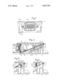
- FIG. 1 is a side view of the electronic control and power unit structure
- FIG. 2 is a longitudinal sectional view along line II--II of FIG. 1;
- FIG. 3 is a fragmentary sectional view along line III--III of FIG. 1;
- FIG. 4 is a fragmentary sectional view similar to FIG. 3 and taken along a similar section line and illustrating another embodiment of the invention.
- Housing 1 (FIGS. 1, 2) is closed off by a cover plate 2.
- the edge of the housing 3 is formed with a groove 5 in which a sealing ring 4 is located.
- the sealing ring is surrounded at two sides by the edge 3 of the housing and at two sides by the cover 2 and a centering lip 6 formed on the cover (see FIGS. 2, 3).
- the sealing ring 4 can be placed in various ways; for example, it can be fitted into a groove in the edge 3 of the housing, surrounded thereby by three sides, the housing 2 pressing at the fourth side against the sealing ring 2.
- the sealing ring can be included in a groove in the housing.
- Housing 1 is formed with attachment eyes 7 and internal attachment projections 8, as well as with cooling ribs 9.
- An opening 10 is formed in the housing opposite the location of the attachment eyes 7.
- the printed circuit board 11 and the connecting strip 12 form one constructional unit.
- the connecting strip 12 is made of insulating material.
- a plurality of connecting terminal lugs, for example eight, are molded into the connecting strip 12.
- Terminal lugs 13 extend with their terminal connecting ends from strip 12.
- the inner ends 14 of the terminal lugs 13 are bent and form contact flags for electrical connection with the electrical connectors on the printed circuit board 11.
- the printed circuit board 11 carries the electronic components 15 of a control circuit and solder junctions 16 for electrical connection with associated circuits.
- the units can be assembled automatically by automatic insertion machines, and then connected by automatic soldering of the connections to the contacts of the printed circuit board, for example by wave soldering.
- the printed circuit board 11 then requires only a single test and adjustment.
- Some of the electronic components 15 may have substantial height; when the unit is used in combination with an electronic ignition system, some of the components 15 may be inductive units, as shown in FIG. 2.
- printed circuit board 11 is located within the housing 1 essentially diagonally, that is, at an inclination with respect to the terminal strip 12.
- the angle of inclination of the printed circuit board 11 depends on the length and the depth of the housing 1 through which printed circuit board 11 extends essentially diagonally.
- the various components of the control electronic portion or stage secured to the printed circuit board are preferably arranged according to height. This permits high packing factor and good space utilization of the space within housing 1. Locating the printed circuit board 11 at an inclination, as shown, permits use of a substantially smaller overall structure than if the elements were located in vertically stacked arrangement. Thus, due to the higher packing density of the elements 15, the length of the housing as well as its height can be reduced with respect to that of adjacent or vertically stacked location of the elements.
- Power stage 18 of the control unit is secured to a base plate 17 by means of screws 19.
- the terminal strip 12, the printed circuit board 11, and the electronic components 15 secured thereto, complete with the solder junction 16, and preferably pre-tested, are inserted in housing 1 by sliding the strip 12 with the section 20 surrounding the terminal lugs 13 into the opening 10 of the housing 1.
- a sealing ring 21 is located between the housing 1 and the terminal strip 12.
- the terminal strip 12 is secured to the housing 1 by means of screws 22.
- Power stage 18 is connected by means of electrical connecting lines 18' (of which only one is shown for simplicity) to the respective solder junction point 16 (of which also only one is shown) to electrically connect the power stage 18 to the printed circuit board 11.
- Housing 1 (FIG. 3) is formed with two notches or grooves 23 at the upper end near the upper terminal portion of the printed circuit board 11.
- a generally U-bent terminal portion 24 of a spring 25 is inserted into the groove 23, the end 26 of which is bent over to dig into the housing and prevent slipping out of spring 25 from the associated groove 23, and to hold the end of the spring 25 securely anchored in the associated groove 23.
- the free end 27 of the leaf spring presses the printed circuit board against the bearing eyes 7. This permits relative sliding movement of the printed circuit board 11 with respect to the bearing eyes 7, and eliminates stresses which could be transferred to the printed circuit board due to differential expansion coefficients between the printed circuit board and the material of the housing.
- the spring 25 is additionally located by projections 28 formed in the interior of the housing 2. Projection 28 presses the spring 25 close to the edge of the material defining the groove 23. An additional cam 29, arranged laterally of the projection 28, increases the spring pressure of spring 28 against the printed circuit board.
- the printed circuit board 11 can be held in position by pinching a rubber, plastic or other elastic strip or bumper 30 between the projections 28, 29, as seen in FIG. 4.
- the rubber bumper 30 presses the printed circuit board 11 against the bearing eyes 7 without, however, preventing expansion or contraction of the printed circuit board under differential temperature conditions.
- the power stage typically transistor 18, is secured to a highly heat-conductive support plate 17 which is screwed by screws 19 tightly against the ribs 8 in the housing, so that good heat transfer and heat dissipation from the power transistor 18 to the housing, and hence cooling of the power transistor are ensured.
- At least the support plate 17 but preferably also the housing are made of good heat-conducting material, for example aluminum or the like.
Abstract
To reduce the overall size of the housing of an electronic control unit having power stages of substantial power, and hence high heat dissipation, in combination with its associated control stage having but little power and hence low heat dissipation, a printed circuit board is located in the structure having essentially rectangular cross section by placing the printed circuit board diagonally therein, holding it in fixed position at one end but loose at the other to permit relative movement with respect to the housing, and thermal dimensional changes, the printed circuit board dividing the chamber into one permitting high heat dissipation and one of low heat dissipation. The structure is particularly applicable for automotive electrical control systems such as, for example, ignition systems for placing in cramped locations.
Description
The present invention relates to an electronic control system and more particularly to an electronic control system for use in automotive vehicular application in which space is at a premium, but which further includes elements of vastly different power capacity and hence heat dissipation.
It has previously been proposed to locate electronic control units in a housing closed off by a cover, the housing including a printed circuit board which supports printed circuits and electronic components which have low heat dissipation, such as control transistors, coupling resistors and the like, and combine such a structure with power components of high heat dissipation. The power components were usually located at the outside, or separately with respect to the control components to permit radiation of heat.
Electronic control elements to which the present invention relates, typically use one or more transistors with the associated coupling resistors, capacitors and other circuit components which are used to control the switching modes of power transistors. The power portion of the control unit to which the invention relates includes one or more power transistors which are used to interrupt current flow, for example to interrupt current flow to the primary winding of an ignition coil.
Electronic control systems having vast differences in dissipated power between the control stage and the power stage usually were so constructed that the control stages, which dissipate little heat, were physically separated from the power stage which dissipates a good deal of heat. The control stage then included the various elements secured, for example, to a printed circuit board; the power transistors or other components dissipating heat in a power stage were then secured to a heat dissipating housing.
An overall electronic control unit has been proposed in which the printed circuit board which carries the control elements for the control electronics separates the housing into an upper and a lower space or chamber. The constructional elements for the control electronics are in the upper chamber; the elements for the power electronics are in the lower chamber. Such a unit has the disadvantage that the vertically staggered construction requires substantial size, that is, effectively a substantial height for the overall housing. In places where space is at a premium - for example under the hood of a motor vehicle, such units require a relatively large space. The interior space or chamber within the relatively large housing is poorly utilized.
It has also been proposed to provide electronic control units in which those elements in the control electronics which are secured to a printed circuit board are located adjacent a chamber of the housing which carries the constructional elements of the power stage. Such an element, while not very high, requires a substantially large placement surface. This, again, is disadvantageous when the unit is to be installed in the limited space available under the hood of automotive vehicles. The space factor of the element also is poor in that the space within the housing itself is not truly utilized.
It is an object of the present invention to provide an electronic control and power unit structure, particularly adapted (although not limited) to automotive electronic ignition systems and which have a control stage and a power stage and which requires little height, small attachment area and permits high packing density of the electronic components within the housing.
Briefly, the housing, in cross section, is essentially rectangular and a printed circuit board is located therein in diagonal direction, separating the interior of the housing in one chamber which includes those elements which have low power, and hence low heat dissipation, so that this chamber will include the elements raising the temperature therein but little; and into another chamber which includes the elements of the power stage.
In accordance with a feature of the invention, the printed circuit board and the components thereon are mechanically isolated from the connectors for external electrical connection in order to isolate the printed circuit board and the associated components from forces which may be unbalanced, off-center or twisting forces arising during connection of an external connector. The printed circuit board is formed as one unit together with a connecting strip to be inserted, for example by sliding, the printed circuit board and connector strip unit into the housing. Externally projecting contact lugs are mechanically secured to the contact strip and electrically with the conductors on the printed circuit board. The printed circuit board is connected electrically to the power stage; the chamber forming the power stage is formed with cooling ribs and the housing is made of a material carrying off heat and acting as a heat sink. Preferably, and in order to avoid temperature stresses and other stresses on the printed circuit board, the printed circuit board is held in the housing by resilient clips, or a rubber or plastic or other resilient holder at least at one end. The spring clips or resilient holders are preferably located in a cover closing off the housing which, in order to prevent moisture and contaminants from entering, is sealed to the remainder of the housing.
The invention will be described by way of example with reference to the accompanying drawings, wherein:
FIG. 1 is a side view of the electronic control and power unit structure;
FIG. 2 is a longitudinal sectional view along line II--II of FIG. 1;
FIG. 3 is a fragmentary sectional view along line III--III of FIG. 1; and
FIG. 4 is a fragmentary sectional view similar to FIG. 3 and taken along a similar section line and illustrating another embodiment of the invention.
Housing 1 (FIGS. 1, 2) is closed off by a cover plate 2. The edge of the housing 3 is formed with a groove 5 in which a sealing ring 4 is located. The sealing ring is surrounded at two sides by the edge 3 of the housing and at two sides by the cover 2 and a centering lip 6 formed on the cover (see FIGS. 2, 3). The sealing ring 4 can be placed in various ways; for example, it can be fitted into a groove in the edge 3 of the housing, surrounded thereby by three sides, the housing 2 pressing at the fourth side against the sealing ring 2. Alternatively, the sealing ring can be included in a groove in the housing.
Housing 1 is formed with attachment eyes 7 and internal attachment projections 8, as well as with cooling ribs 9. An opening 10 is formed in the housing opposite the location of the attachment eyes 7.
A printed circuit board 11, to which a printed circuit board is applied, is riveted to a connecting strip 12 by means of speed rivets 12'. The printed circuit board 11 and the connecting strip 12 form one constructional unit. The connecting strip 12 is made of insulating material. A plurality of connecting terminal lugs, for example eight, are molded into the connecting strip 12. Terminal lugs 13 extend with their terminal connecting ends from strip 12. The inner ends 14 of the terminal lugs 13 are bent and form contact flags for electrical connection with the electrical connectors on the printed circuit board 11. The printed circuit board 11 carries the electronic components 15 of a control circuit and solder junctions 16 for electrical connection with associated circuits. In mass production, the units can be assembled automatically by automatic insertion machines, and then connected by automatic soldering of the connections to the contacts of the printed circuit board, for example by wave soldering. The printed circuit board 11 then requires only a single test and adjustment. Some of the electronic components 15 may have substantial height; when the unit is used in combination with an electronic ignition system, some of the components 15 may be inductive units, as shown in FIG. 2.
In accordance with the invention, printed circuit board 11 is located within the housing 1 essentially diagonally, that is, at an inclination with respect to the terminal strip 12. The angle of inclination of the printed circuit board 11 depends on the length and the depth of the housing 1 through which printed circuit board 11 extends essentially diagonally. The various components of the control electronic portion or stage secured to the printed circuit board are preferably arranged according to height. This permits high packing factor and good space utilization of the space within housing 1. Locating the printed circuit board 11 at an inclination, as shown, permits use of a substantially smaller overall structure than if the elements were located in vertically stacked arrangement. Thus, due to the higher packing density of the elements 15, the length of the housing as well as its height can be reduced with respect to that of adjacent or vertically stacked location of the elements.
Power stage 18 of the control unit is secured to a base plate 17 by means of screws 19.
The terminal strip 12, the printed circuit board 11, and the electronic components 15 secured thereto, complete with the solder junction 16, and preferably pre-tested, are inserted in housing 1 by sliding the strip 12 with the section 20 surrounding the terminal lugs 13 into the opening 10 of the housing 1. A sealing ring 21 is located between the housing 1 and the terminal strip 12. The terminal strip 12 is secured to the housing 1 by means of screws 22.
Power stage 18 is connected by means of electrical connecting lines 18' (of which only one is shown for simplicity) to the respective solder junction point 16 (of which also only one is shown) to electrically connect the power stage 18 to the printed circuit board 11.
Housing 1 (FIG. 3) is formed with two notches or grooves 23 at the upper end near the upper terminal portion of the printed circuit board 11. A generally U-bent terminal portion 24 of a spring 25 is inserted into the groove 23, the end 26 of which is bent over to dig into the housing and prevent slipping out of spring 25 from the associated groove 23, and to hold the end of the spring 25 securely anchored in the associated groove 23. The free end 27 of the leaf spring presses the printed circuit board against the bearing eyes 7. This permits relative sliding movement of the printed circuit board 11 with respect to the bearing eyes 7, and eliminates stresses which could be transferred to the printed circuit board due to differential expansion coefficients between the printed circuit board and the material of the housing.
The spring 25 is additionally located by projections 28 formed in the interior of the housing 2. Projection 28 presses the spring 25 close to the edge of the material defining the groove 23. An additional cam 29, arranged laterally of the projection 28, increases the spring pressure of spring 28 against the printed circuit board.
Various changes and modifications may be made; for example the printed circuit board 11 can be held in position by pinching a rubber, plastic or other elastic strip or bumper 30 between the projections 28, 29, as seen in FIG. 4. The rubber bumper 30 presses the printed circuit board 11 against the bearing eyes 7 without, however, preventing expansion or contraction of the printed circuit board under differential temperature conditions.
Various other changes and modifications may be made, and features described in connection with any one of the embodiments may be used with any other within the inventive concept.
The power stage, typically transistor 18, is secured to a highly heat-conductive support plate 17 which is screwed by screws 19 tightly against the ribs 8 in the housing, so that good heat transfer and heat dissipation from the power transistor 18 to the housing, and hence cooling of the power transistor are ensured. At least the support plate 17 but preferably also the housing are made of good heat-conducting material, for example aluminum or the like.
Connecting stresses between the terminal lugs 13 of the connecting terminal and the printed circuit board 11 are effectively isolated from each other by the separate rivet connection effected by speed rivets 12' of the printed circuit board to the housing.
Claims (11)
1. Compact electronic control and power unit structure having
a housing (1) of essentially rectangular cross section, a printed circuit board (11) located in the housing and carrying control elements and electrical conductors having relatively low heat generation, and a power stage (18), having relatively high heat generation, located in the housing;
wherein, in accordance with the invention, said printed circuit board is located essentially diagonally across said substantially rectangular cross section in the housing and sub-dividing the interior of the space in the housing into two chambers, one chamber having said control elements and electrical conductors having relatively low heat generation located therein and the other chamber having said power stage (18) located therein.
2. Structure according to claim 1, wherein a connecting strip (12) carrying connecting terminals (13) is provided, secured to the printed circuit board (11) and forming one constructional unit therewith, the connecting terminals (13) projecting outside of the housing from the connecting strip and carrying internally extending extensions (14) electrically connected to electrical conductors on the printed circuit board (11).
3. Structure according to claim 2, wherein the ends (13) of the connecting terminals form terminal lugs for external connection and extend outside of the housing, the internal portions of the connecting terminals being connected to the printed circuit board;
and means (12') securing the printed circuit board in the housing to prevent transfer of connecting stresses applied against the externally projecting ends (13) of the connecting terminals to the printed circuit board (11).
4. Structure according to claim 1, wherein the housing is formed with cooling ribs (9) of heat-conductive material, the components of the power stage being secured in thermal communication with said cooling ribs;
and electrical connection means (16) are provided, electrically connecting the power stage (18) to the printed circuit board.
5. Structure according to claim 4, further comprising a support plate (17) for the components of the power stage (18) secured in heat-conductive relation to said cooling ribs of the housing and to the power-dissipating components of the power stage.
6. Structure according to claim 1, further comprising means (25; 30) resiliently securing the printed circuit board (11) within the housing to permit relative movement of the printed circuit board and the housing and hence differential expansion under changing thermal conditions.
7. Structure according to claim 6, wherein said resilient means comprises a spring (26) located within the housing (1) and holding the printed circuit board (11) against a shoulder (7) formed in the housing.
8. Structure according to claim 6, wherein the resilient means comprises bumper means (30) of resiliently compressible material engaging the contact strip (11) and pressing the contact strip against a support surface (7) formed in the housing while permitting relative sliding movement of the printed circuit board (11) and the housing.
9. Structure according to claim 1, further comprising sealing means sealing the cover of the housing.
10. Structure according to claim 3, further comprising sealing means sealing the cover of the housing and the contact strip against the outside of the housing to prevent penetration of moisture and contamination into the interior of the housing.
11. A structure according to claim 1 further forming a semiconductor electronic ignition system comprising a control stage including inductive components secured to said printed circuit board and located at one side thereof, and forming a portion of the control elements therefor, and at least one power transistor (18) forming the power stage.
Applications Claiming Priority (2)
| Application Number | Priority Date | Filing Date | Title |
|---|---|---|---|
| DT2530157 | 1975-07-05 | ||
| DE19752530157 DE2530157A1 (en) | 1975-07-05 | 1975-07-05 | ELECTRONIC CONTROL UNIT |
Publications (1)
| Publication Number | Publication Date |
|---|---|
| US4047242A true US4047242A (en) | 1977-09-06 |
Family
ID=5950812
Family Applications (1)
| Application Number | Title | Priority Date | Filing Date |
|---|---|---|---|
| US05/682,061 Expired - Lifetime US4047242A (en) | 1975-07-05 | 1976-04-30 | Compact electronic control and power unit structure |
Country Status (5)
| Country | Link |
|---|---|
| US (1) | US4047242A (en) |
| JP (1) | JPS529377A (en) |
| AU (1) | AU1485976A (en) |
| DE (1) | DE2530157A1 (en) |
| GB (1) | GB1526321A (en) |
Cited By (68)
| Publication number | Priority date | Publication date | Assignee | Title |
|---|---|---|---|---|
| US4196467A (en) * | 1977-03-26 | 1980-04-01 | Robert Bosch Gmbh | Electronic system housing structure, particularly for automotive environments |
| US4241380A (en) * | 1977-03-10 | 1980-12-23 | Danfoss A/S | Housing for an electric circuit arrangement |
| US4313025A (en) * | 1980-06-04 | 1982-01-26 | Motorola, Inc. | Unitary die-cast assembly for electronic circuits |
| DE3040097A1 (en) * | 1980-10-24 | 1982-05-27 | Tekmar Angewandte Elektronik Gmbh & Co Kg, 4300 Essen | Housing for electronic circuit card - has cards held in container with plug and socket assembly in base |
| US4355853A (en) * | 1977-05-21 | 1982-10-26 | Amp Incorporated | Electrical junction box |
| US4409641A (en) * | 1980-06-02 | 1983-10-11 | Robert Bosch Gmbh | Environmentally protected electronic network structure and housing combination |
| US4513354A (en) * | 1983-09-26 | 1985-04-23 | Sentrol, Inc. | Housing for an electronic circuit board |
| US4568873A (en) * | 1982-03-23 | 1986-02-04 | Iwatsu Electric Co., Ltd. | Easy-to-assemble capacitive probe for a high precision dimensional or distance gage |
| US4604529A (en) * | 1984-09-28 | 1986-08-05 | Cincinnati Microwave, Inc. | Radar warning receiver with power plug |
| US4697863A (en) * | 1985-10-22 | 1987-10-06 | Amp Incorporated | Electrical connector assembly for antiskid braking system |
| US4729740A (en) * | 1986-12-12 | 1988-03-08 | Amp Incorporated | Fluorescent ballast having integral connector |
| US4785532A (en) * | 1985-10-22 | 1988-11-22 | Amp Incorporated | Method of making electrical connector assembly for antiskid braking system |
| US4905123A (en) * | 1987-10-08 | 1990-02-27 | Navistar International Transportation Corp. | Heat sink bus assembly |
| US4993956A (en) * | 1989-11-01 | 1991-02-19 | Amp Incorporated | Active electrical connector |
| US5053923A (en) * | 1988-11-09 | 1991-10-01 | Telefunken Electronic Gmbh | Electronic control unit with common ground connection to a heat sink |
| US5153449A (en) * | 1990-08-28 | 1992-10-06 | Milwaukee Electric Tool Corporation | Heatsink bus for electronic switch |
| US5159532A (en) * | 1988-11-09 | 1992-10-27 | Telefunken Electronic Gmbh | Electronic control unit with multiple hybrid circuit assemblies integrated on a single common ceramic carrier |
| US5289345A (en) * | 1989-05-19 | 1994-02-22 | Bt&D Technologies Ltd. | Opto-electronic device housing having self-healing elastomeric board mount with support pylons |
| US5587884A (en) * | 1995-02-06 | 1996-12-24 | The Whitaker Corporation | Electrical connector jack with encapsulated signal conditioning components |
| WO1997002729A1 (en) * | 1995-07-06 | 1997-01-23 | Danfoss A/S | Compressor with control electronics |
| US5647767A (en) * | 1995-02-06 | 1997-07-15 | The Whitaker Corporation | Electrical connector jack assembly for signal transmission |
| WO1998056225A1 (en) * | 1997-06-03 | 1998-12-10 | Telefonaktiebolaget Lm Ericsson | Method and device for cooling and protecting electronic equipment |
| US5984720A (en) * | 1997-10-17 | 1999-11-16 | Hubbell Incorporated | Angled interconnect panel assembly for telecommunications applications |
| US6169654B1 (en) | 1996-01-17 | 2001-01-02 | Wabco Gmbh | Housing for electric componentry |
| US6179627B1 (en) * | 1998-04-22 | 2001-01-30 | Stratos Lightwave, Inc. | High speed interface converter module |
| US6377462B1 (en) | 2001-01-09 | 2002-04-23 | Deere & Company | Circuit board assembly with heat sinking |
| US6574107B2 (en) * | 2000-11-10 | 2003-06-03 | Fairchild Korea Semiconductor Ltd. | Stacked intelligent power module package |
| US6590774B2 (en) | 1993-12-27 | 2003-07-08 | Hitachi, Ltd. | Ignition apparatus for internal combustion engine with improved electrical insulation plate including beryllia |
| DE19516936C2 (en) * | 1995-05-09 | 2003-07-17 | Conti Temic Microelectronic | Method of manufacturing a metal housing with a plug socket |
| US20030206392A1 (en) * | 2002-04-17 | 2003-11-06 | Hiroyuki Kawata | Switching device for controlling large amount of current |
| US6669505B2 (en) * | 2001-09-13 | 2003-12-30 | Siemens Vdo Automotive Corporation | Vehicle electronic control units |
| WO2004045264A1 (en) * | 2002-11-14 | 2004-05-27 | Packetfront Sweden Ab | A housing for electronic circuits and components |
| US6758200B2 (en) * | 2002-08-06 | 2004-07-06 | Delphi Technologies, Inc. | Ignition coil driver chip on printed circuit board for plughole coil housing |
| US6773272B2 (en) * | 2002-04-22 | 2004-08-10 | Molex Incorporated | Electrical connector assembly and module incorporating the same |
| US20040172986A1 (en) * | 2002-04-17 | 2004-09-09 | Heo Seong Eun | Washer |
| US20040247080A1 (en) * | 2003-03-04 | 2004-12-09 | Feda Francis Michael | Systems and methods for controlling an X-ray source |
| FR2870667A1 (en) * | 2004-05-24 | 2005-11-25 | Mitsubishi Electric Corp | POWER CONVERSION DEVICE |
| DE102004031403A1 (en) * | 2004-06-29 | 2006-02-02 | Siemens Ag | Switching module comprises a carrier and a housing section that forms a hollow chamber |
| US7035111B1 (en) * | 2003-05-23 | 2006-04-25 | Hewlett-Packard Development Company, L.P. | Circuit board orientation with different width portions |
| US20060098778A1 (en) * | 2002-02-20 | 2006-05-11 | Oettinger Peter E | Integrated X-ray source module |
| US20060164810A1 (en) * | 2003-02-28 | 2006-07-27 | Walter Apfelbacher | Electronic device comprising secure heat dissipation |
| US7190589B2 (en) | 2004-10-19 | 2007-03-13 | Cinch Connectors, Inc. | Electronic control enclosure |
| US20070127222A1 (en) * | 2005-12-07 | 2007-06-07 | Mitsubishi Denki Kabushiki Kaisha | Electronic device |
| US20070272976A1 (en) * | 2006-05-09 | 2007-11-29 | Semikron Elektronik Gmbh & Co. Kg | Power semiconductor module |
| USRE40150E1 (en) | 1994-04-25 | 2008-03-11 | Matsushita Electric Industrial Co., Ltd. | Fiber optic module |
| WO2008039990A2 (en) * | 2006-09-28 | 2008-04-03 | Tk Holdings Inc. | Electronic control module |
| US20090203269A1 (en) * | 2006-05-12 | 2009-08-13 | Baumer Electric Ag | Proximity switch and method for contacting a sensor pcb |
| US20090266091A1 (en) * | 2005-08-03 | 2009-10-29 | Bristol Compressors International, Inc. | System and method for compressor capacity modulation in a heat pump |
| DE102008022061A1 (en) * | 2008-05-03 | 2009-11-05 | Conti Temic Microelectronic Gmbh | Vehicle accident detecting component, has printed circuit board with direction-sensitive sensor and assembly opening in housing, where assembly opening is arranged in printed circuit board at specific angle |
| US20090324427A1 (en) * | 2008-06-29 | 2009-12-31 | Tolbert Jr John W | System and method for starting a compressor |
| US20100083680A1 (en) * | 2005-08-03 | 2010-04-08 | Tolbert Jr John W | System for compressor capacity modulation |
| US20110230062A1 (en) * | 2010-03-19 | 2011-09-22 | Kabushiki Kaisha Yaskawa Denki | Electronic apparatus |
| US8601828B2 (en) | 2009-04-29 | 2013-12-10 | Bristol Compressors International, Inc. | Capacity control systems and methods for a compressor |
| US20140102192A1 (en) * | 2011-04-27 | 2014-04-17 | Mitutoyo Corporation | Dust-proof structure for measuring tool |
| US8726729B2 (en) * | 2012-03-22 | 2014-05-20 | Krohne Messtechnik Gmbh | Measuring device |
| US20140196946A1 (en) * | 2011-07-01 | 2014-07-17 | Tyco Electronics Belgium Ec Bvba | Module for a braking system, such as a coil box module comprising a housing and a connector |
| US20140227908A1 (en) * | 2013-02-08 | 2014-08-14 | Hitachi Metals, Ltd. | Connector supporting structure and connector-equipped electronic device |
| US9030190B2 (en) | 2012-03-22 | 2015-05-12 | Krohne Messtechnik Gmbh | Measuring device |
| DE10045728B4 (en) * | 1999-09-17 | 2015-08-20 | Denso Corporation | Housing for an electronic control unit and arrangement of such a housing and an electronic circuit unit |
| US9293870B1 (en) * | 2015-03-10 | 2016-03-22 | Continental Automotive Systems, Inc. | Electronic control module having a cover allowing for inspection of right angle press-fit pins |
| US9685593B2 (en) | 2013-11-25 | 2017-06-20 | Osram Opto Semiconductors Gmbh | Housing for a semiconductor chip, housing composite, semiconductor component and method of producing a semiconductor component |
| CN107079607A (en) * | 2016-11-14 | 2017-08-18 | 深圳市大疆创新科技有限公司 | One kind electromagnetic shielding cooling system and unmanned plane |
| US20180006390A1 (en) * | 2015-03-13 | 2018-01-04 | Te Connectivity Germany Gmbh | Electrical Connector, Electronic Component, and Assembly Method |
| US10082849B2 (en) | 2015-06-01 | 2018-09-25 | International Business Machines Corporation | Optimizing cooling energy for a reconfigurable computer system |
| US20190011295A1 (en) * | 2017-07-07 | 2019-01-10 | Krohne Messtechnik Gmbh | Measuring device, transmitter housing and method for producing a measuring device |
| US10700462B2 (en) | 2018-01-18 | 2020-06-30 | Interplex Industries, Inc. | Connector housing |
| US11079813B2 (en) * | 2019-05-24 | 2021-08-03 | Asustek Computer Inc. | Computer case |
| US20210378112A1 (en) * | 2020-05-26 | 2021-12-02 | Kabushiki Kaisha Honda Lock | Structure for connecting terminal to circuit substrate within case |
Families Citing this family (12)
| Publication number | Priority date | Publication date | Assignee | Title |
|---|---|---|---|---|
| DE2845661A1 (en) * | 1978-10-20 | 1980-05-08 | Bosch Gmbh Robert | Intake air flow measure for combustion engine - uses cooling of hot wire resistor in regulated bridge network |
| DE3310477A1 (en) * | 1982-07-17 | 1984-01-19 | Robert Bosch Gmbh, 7000 Stuttgart | Electrical apparatus, especially a switching and control apparatus for motor vehicles |
| DE3305167C2 (en) * | 1983-02-15 | 1994-05-05 | Bosch Gmbh Robert | Electrical circuit arrangement with a circuit board |
| JPS60109387U (en) * | 1983-12-28 | 1985-07-25 | アルプス電気株式会社 | Heat generating element radiation heat prevention structure |
| JPS6297081A (en) * | 1986-10-08 | 1987-05-06 | Hitachi Ltd | Character recognizer |
| DE4012182A1 (en) * | 1990-04-14 | 1991-10-17 | Bosch Gmbh Robert | ELECTRICAL SWITCHING AND CONTROL UNIT, ESPECIALLY FOR MOTOR VEHICLES |
| ATE117163T1 (en) * | 1990-10-24 | 1995-01-15 | Asea Brown Boveri | INPUT AND/OR OUTPUT DEVICE FOR PROCESS DATA. |
| JPH081995B2 (en) * | 1990-12-25 | 1996-01-10 | 山一電機株式会社 | Hybrid board built-in connector |
| SE516315C2 (en) | 1994-11-07 | 2001-12-17 | Atlas Copco Controls Ab | Control circuit arrangement for a drive unit for an electric motor |
| SE505272C2 (en) * | 1994-12-14 | 1997-07-28 | Ericsson Telefon Ab L M | Cooling system for telecommunications equipment |
| DE10034572A1 (en) * | 2000-07-14 | 2002-01-24 | Webasto Thermosysteme Gmbh | Heater with a cooling system for a power transistor in which transistor is held in contact with outer metal housing |
| DE102020207712A1 (en) | 2020-06-22 | 2021-12-23 | Eberspächer Catem Gmbh & Co. Kg | Control device |
Citations (5)
| Publication number | Priority date | Publication date | Assignee | Title |
|---|---|---|---|---|
| US2777893A (en) * | 1954-03-15 | 1957-01-15 | Clary Corp | Mounting for electrical equipment |
| US2958013A (en) * | 1956-08-20 | 1960-10-25 | Arthur Ansley Mfg Co | Electrical unit |
| US3479568A (en) * | 1968-05-13 | 1969-11-18 | Aerospace Res | Instrument housing |
| US3852643A (en) * | 1972-02-07 | 1974-12-03 | Matsushita Electric Ind Co Ltd | Printed circuit board assembly and heat sink |
| US3934177A (en) * | 1975-01-09 | 1976-01-20 | Stephen Horbach | Heat sink casing for circuit board components |
-
1975
- 1975-07-05 DE DE19752530157 patent/DE2530157A1/en active Pending
-
1976
- 1976-04-30 US US05/682,061 patent/US4047242A/en not_active Expired - Lifetime
- 1976-06-11 AU AU14859/76A patent/AU1485976A/en not_active Expired
- 1976-07-01 GB GB27410/76A patent/GB1526321A/en not_active Expired
- 1976-07-02 JP JP51078821A patent/JPS529377A/en active Pending
Patent Citations (5)
| Publication number | Priority date | Publication date | Assignee | Title |
|---|---|---|---|---|
| US2777893A (en) * | 1954-03-15 | 1957-01-15 | Clary Corp | Mounting for electrical equipment |
| US2958013A (en) * | 1956-08-20 | 1960-10-25 | Arthur Ansley Mfg Co | Electrical unit |
| US3479568A (en) * | 1968-05-13 | 1969-11-18 | Aerospace Res | Instrument housing |
| US3852643A (en) * | 1972-02-07 | 1974-12-03 | Matsushita Electric Ind Co Ltd | Printed circuit board assembly and heat sink |
| US3934177A (en) * | 1975-01-09 | 1976-01-20 | Stephen Horbach | Heat sink casing for circuit board components |
Cited By (104)
| Publication number | Priority date | Publication date | Assignee | Title |
|---|---|---|---|---|
| US4241380A (en) * | 1977-03-10 | 1980-12-23 | Danfoss A/S | Housing for an electric circuit arrangement |
| US4196467A (en) * | 1977-03-26 | 1980-04-01 | Robert Bosch Gmbh | Electronic system housing structure, particularly for automotive environments |
| US4355853A (en) * | 1977-05-21 | 1982-10-26 | Amp Incorporated | Electrical junction box |
| US4409641A (en) * | 1980-06-02 | 1983-10-11 | Robert Bosch Gmbh | Environmentally protected electronic network structure and housing combination |
| US4313025A (en) * | 1980-06-04 | 1982-01-26 | Motorola, Inc. | Unitary die-cast assembly for electronic circuits |
| DE3040097A1 (en) * | 1980-10-24 | 1982-05-27 | Tekmar Angewandte Elektronik Gmbh & Co Kg, 4300 Essen | Housing for electronic circuit card - has cards held in container with plug and socket assembly in base |
| US4568873A (en) * | 1982-03-23 | 1986-02-04 | Iwatsu Electric Co., Ltd. | Easy-to-assemble capacitive probe for a high precision dimensional or distance gage |
| US4513354A (en) * | 1983-09-26 | 1985-04-23 | Sentrol, Inc. | Housing for an electronic circuit board |
| US4604529A (en) * | 1984-09-28 | 1986-08-05 | Cincinnati Microwave, Inc. | Radar warning receiver with power plug |
| US4842525A (en) * | 1985-10-22 | 1989-06-27 | Amp Incorporated | Electrical connector assembly for antiskid braking system |
| US4785532A (en) * | 1985-10-22 | 1988-11-22 | Amp Incorporated | Method of making electrical connector assembly for antiskid braking system |
| US4697863A (en) * | 1985-10-22 | 1987-10-06 | Amp Incorporated | Electrical connector assembly for antiskid braking system |
| US4729740A (en) * | 1986-12-12 | 1988-03-08 | Amp Incorporated | Fluorescent ballast having integral connector |
| US4905123A (en) * | 1987-10-08 | 1990-02-27 | Navistar International Transportation Corp. | Heat sink bus assembly |
| US5159532A (en) * | 1988-11-09 | 1992-10-27 | Telefunken Electronic Gmbh | Electronic control unit with multiple hybrid circuit assemblies integrated on a single common ceramic carrier |
| US5053923A (en) * | 1988-11-09 | 1991-10-01 | Telefunken Electronic Gmbh | Electronic control unit with common ground connection to a heat sink |
| US5289345A (en) * | 1989-05-19 | 1994-02-22 | Bt&D Technologies Ltd. | Opto-electronic device housing having self-healing elastomeric board mount with support pylons |
| US4993956A (en) * | 1989-11-01 | 1991-02-19 | Amp Incorporated | Active electrical connector |
| US5153449A (en) * | 1990-08-28 | 1992-10-06 | Milwaukee Electric Tool Corporation | Heatsink bus for electronic switch |
| US6590774B2 (en) | 1993-12-27 | 2003-07-08 | Hitachi, Ltd. | Ignition apparatus for internal combustion engine with improved electrical insulation plate including beryllia |
| USRE40154E1 (en) | 1994-04-25 | 2008-03-18 | Matsushita Electric Industrial Co., Ltd. | Fiber optic module |
| USRE40150E1 (en) | 1994-04-25 | 2008-03-11 | Matsushita Electric Industrial Co., Ltd. | Fiber optic module |
| US5587884A (en) * | 1995-02-06 | 1996-12-24 | The Whitaker Corporation | Electrical connector jack with encapsulated signal conditioning components |
| US5647767A (en) * | 1995-02-06 | 1997-07-15 | The Whitaker Corporation | Electrical connector jack assembly for signal transmission |
| DE19516936C2 (en) * | 1995-05-09 | 2003-07-17 | Conti Temic Microelectronic | Method of manufacturing a metal housing with a plug socket |
| WO1997002729A1 (en) * | 1995-07-06 | 1997-01-23 | Danfoss A/S | Compressor with control electronics |
| US6041609A (en) * | 1995-07-06 | 2000-03-28 | Danfoss A/S | Compressor with control electronics |
| US6169654B1 (en) | 1996-01-17 | 2001-01-02 | Wabco Gmbh | Housing for electric componentry |
| WO1998056225A1 (en) * | 1997-06-03 | 1998-12-10 | Telefonaktiebolaget Lm Ericsson | Method and device for cooling and protecting electronic equipment |
| US6002585A (en) * | 1997-06-03 | 1999-12-14 | Telefonaktiebolaget Lm Ericsson | Device and method for cooling and protecting electronics |
| US5984720A (en) * | 1997-10-17 | 1999-11-16 | Hubbell Incorporated | Angled interconnect panel assembly for telecommunications applications |
| US6179627B1 (en) * | 1998-04-22 | 2001-01-30 | Stratos Lightwave, Inc. | High speed interface converter module |
| DE10045728B4 (en) * | 1999-09-17 | 2015-08-20 | Denso Corporation | Housing for an electronic control unit and arrangement of such a housing and an electronic circuit unit |
| US6574107B2 (en) * | 2000-11-10 | 2003-06-03 | Fairchild Korea Semiconductor Ltd. | Stacked intelligent power module package |
| US6377462B1 (en) | 2001-01-09 | 2002-04-23 | Deere & Company | Circuit board assembly with heat sinking |
| US6669505B2 (en) * | 2001-09-13 | 2003-12-30 | Siemens Vdo Automotive Corporation | Vehicle electronic control units |
| US20060098778A1 (en) * | 2002-02-20 | 2006-05-11 | Oettinger Peter E | Integrated X-ray source module |
| US7448801B2 (en) * | 2002-02-20 | 2008-11-11 | Inpho, Inc. | Integrated X-ray source module |
| US7418838B2 (en) * | 2002-04-17 | 2008-09-02 | Lg Electronics Inc. | Washer |
| US20040172986A1 (en) * | 2002-04-17 | 2004-09-09 | Heo Seong Eun | Washer |
| US7081691B2 (en) * | 2002-04-17 | 2006-07-25 | Denso Corporation | Switching device for controlling large amount of current |
| US20030206392A1 (en) * | 2002-04-17 | 2003-11-06 | Hiroyuki Kawata | Switching device for controlling large amount of current |
| US6773272B2 (en) * | 2002-04-22 | 2004-08-10 | Molex Incorporated | Electrical connector assembly and module incorporating the same |
| US6758200B2 (en) * | 2002-08-06 | 2004-07-06 | Delphi Technologies, Inc. | Ignition coil driver chip on printed circuit board for plughole coil housing |
| WO2004045264A1 (en) * | 2002-11-14 | 2004-05-27 | Packetfront Sweden Ab | A housing for electronic circuits and components |
| US7515421B2 (en) * | 2003-02-28 | 2009-04-07 | Siemens Aktiengesellschaft | Electronic device comprising secure heat dissipation |
| US20060164810A1 (en) * | 2003-02-28 | 2006-07-27 | Walter Apfelbacher | Electronic device comprising secure heat dissipation |
| US7233645B2 (en) | 2003-03-04 | 2007-06-19 | Inpho, Inc. | Systems and methods for controlling an X-ray source |
| US7639784B2 (en) | 2003-03-04 | 2009-12-29 | Francis Michael Feda | Systems and methods for controlling an x-ray source |
| US20080123815A1 (en) * | 2003-03-04 | 2008-05-29 | Inpho, Inc. | Systems and methods for controlling an x-ray source |
| US20040247080A1 (en) * | 2003-03-04 | 2004-12-09 | Feda Francis Michael | Systems and methods for controlling an X-ray source |
| US7035111B1 (en) * | 2003-05-23 | 2006-04-25 | Hewlett-Packard Development Company, L.P. | Circuit board orientation with different width portions |
| FR2870667A1 (en) * | 2004-05-24 | 2005-11-25 | Mitsubishi Electric Corp | POWER CONVERSION DEVICE |
| DE102004031403A1 (en) * | 2004-06-29 | 2006-02-02 | Siemens Ag | Switching module comprises a carrier and a housing section that forms a hollow chamber |
| US20070147004A1 (en) * | 2004-10-19 | 2007-06-28 | Cinch Connectors, Inc. | Electronic control enclosure |
| US7542294B2 (en) | 2004-10-19 | 2009-06-02 | Cinch Connectors, Inc. | Electronic control enclosure |
| US7369413B2 (en) | 2004-10-19 | 2008-05-06 | Cinch Connectors, Inc. | Electronic control enclosure |
| US7190589B2 (en) | 2004-10-19 | 2007-03-13 | Cinch Connectors, Inc. | Electronic control enclosure |
| US20070153485A1 (en) * | 2004-10-19 | 2007-07-05 | Cinch Connectors, Inc. | Electronic control enclosure |
| US20070153484A1 (en) * | 2004-10-19 | 2007-07-05 | Cinch Connectors, Inc. | Electronic control enclosure |
| US7946123B2 (en) | 2005-08-03 | 2011-05-24 | Bristol Compressors International, Inc. | System for compressor capacity modulation |
| US8650894B2 (en) | 2005-08-03 | 2014-02-18 | Bristol Compressors International, Inc. | System and method for compressor capacity modulation in a heat pump |
| US20090266091A1 (en) * | 2005-08-03 | 2009-10-29 | Bristol Compressors International, Inc. | System and method for compressor capacity modulation in a heat pump |
| US20100083680A1 (en) * | 2005-08-03 | 2010-04-08 | Tolbert Jr John W | System for compressor capacity modulation |
| US7436677B2 (en) * | 2005-12-07 | 2008-10-14 | Mitsubishi Denki Kabushiki Kaisha | Electronic device |
| US20070127222A1 (en) * | 2005-12-07 | 2007-06-07 | Mitsubishi Denki Kabushiki Kaisha | Electronic device |
| US7495324B2 (en) * | 2006-05-09 | 2009-02-24 | Semikron Elektronik Gmbh & Co. Kg | Power semiconductor module |
| US20070272976A1 (en) * | 2006-05-09 | 2007-11-29 | Semikron Elektronik Gmbh & Co. Kg | Power semiconductor module |
| US20090203269A1 (en) * | 2006-05-12 | 2009-08-13 | Baumer Electric Ag | Proximity switch and method for contacting a sensor pcb |
| WO2008039990A3 (en) * | 2006-09-28 | 2008-07-10 | Tk Holdings Inc | Electronic control module |
| WO2008039990A2 (en) * | 2006-09-28 | 2008-04-03 | Tk Holdings Inc. | Electronic control module |
| US20080080147A1 (en) * | 2006-09-28 | 2008-04-03 | Tk Holdings Inc. | Electronic control module |
| DE102008022061A1 (en) * | 2008-05-03 | 2009-11-05 | Conti Temic Microelectronic Gmbh | Vehicle accident detecting component, has printed circuit board with direction-sensitive sensor and assembly opening in housing, where assembly opening is arranged in printed circuit board at specific angle |
| US8672642B2 (en) | 2008-06-29 | 2014-03-18 | Bristol Compressors International, Inc. | System and method for starting a compressor |
| US20090324428A1 (en) * | 2008-06-29 | 2009-12-31 | Tolbert Jr John W | System and method for detecting a fault condition in a compressor |
| US8790089B2 (en) | 2008-06-29 | 2014-07-29 | Bristol Compressors International, Inc. | Compressor speed control system for bearing reliability |
| US20090324426A1 (en) * | 2008-06-29 | 2009-12-31 | Moody Bruce A | Compressor speed control system for bearing reliability |
| US20090324427A1 (en) * | 2008-06-29 | 2009-12-31 | Tolbert Jr John W | System and method for starting a compressor |
| US8904814B2 (en) | 2008-06-29 | 2014-12-09 | Bristol Compressors, International Inc. | System and method for detecting a fault condition in a compressor |
| US8601828B2 (en) | 2009-04-29 | 2013-12-10 | Bristol Compressors International, Inc. | Capacity control systems and methods for a compressor |
| US20110230062A1 (en) * | 2010-03-19 | 2011-09-22 | Kabushiki Kaisha Yaskawa Denki | Electronic apparatus |
| US8142205B2 (en) * | 2010-03-19 | 2012-03-27 | Kabushiki Kaisha Yaskawa Denki | Electronic apparatus |
| US9016122B2 (en) * | 2011-04-27 | 2015-04-28 | Mitutoyo Corporation | Dust-proof structure for measuring tool |
| US20140102192A1 (en) * | 2011-04-27 | 2014-04-17 | Mitutoyo Corporation | Dust-proof structure for measuring tool |
| US20140196946A1 (en) * | 2011-07-01 | 2014-07-17 | Tyco Electronics Belgium Ec Bvba | Module for a braking system, such as a coil box module comprising a housing and a connector |
| DE102012005638C5 (en) | 2012-03-22 | 2018-03-29 | Krohne Messtechnik Gmbh | gauge |
| US8726729B2 (en) * | 2012-03-22 | 2014-05-20 | Krohne Messtechnik Gmbh | Measuring device |
| US9030190B2 (en) | 2012-03-22 | 2015-05-12 | Krohne Messtechnik Gmbh | Measuring device |
| US9197002B2 (en) * | 2013-02-08 | 2015-11-24 | Hitachi Metals, Ltd. | Connector supporting structure and connector-equipped electronic device |
| US20140227908A1 (en) * | 2013-02-08 | 2014-08-14 | Hitachi Metals, Ltd. | Connector supporting structure and connector-equipped electronic device |
| US9685593B2 (en) | 2013-11-25 | 2017-06-20 | Osram Opto Semiconductors Gmbh | Housing for a semiconductor chip, housing composite, semiconductor component and method of producing a semiconductor component |
| US9293870B1 (en) * | 2015-03-10 | 2016-03-22 | Continental Automotive Systems, Inc. | Electronic control module having a cover allowing for inspection of right angle press-fit pins |
| US10403995B2 (en) * | 2015-03-13 | 2019-09-03 | Te Connectivity Germany Gmbh | Electrical connector, electronic component, and assembly method |
| US20180006390A1 (en) * | 2015-03-13 | 2018-01-04 | Te Connectivity Germany Gmbh | Electrical Connector, Electronic Component, and Assembly Method |
| US10082849B2 (en) | 2015-06-01 | 2018-09-25 | International Business Machines Corporation | Optimizing cooling energy for a reconfigurable computer system |
| US10528096B2 (en) | 2015-06-01 | 2020-01-07 | International Business Machines Corporation | Optimizing cooling energy |
| WO2018086108A1 (en) * | 2016-11-14 | 2018-05-17 | 深圳市大疆创新科技有限公司 | Electromagnetic shielding cooling system, and unmanned aerial vehicle |
| CN107079607B (en) * | 2016-11-14 | 2019-05-14 | 深圳市大疆创新科技有限公司 | A kind of electromagnetic shielding cooling system and unmanned plane |
| CN107079607A (en) * | 2016-11-14 | 2017-08-18 | 深圳市大疆创新科技有限公司 | One kind electromagnetic shielding cooling system and unmanned plane |
| US20190011295A1 (en) * | 2017-07-07 | 2019-01-10 | Krohne Messtechnik Gmbh | Measuring device, transmitter housing and method for producing a measuring device |
| US11125588B2 (en) * | 2017-07-07 | 2021-09-21 | Krohne Messtechnik Gmbh | Measuring device, transmitter housing and method for producing a measuring device |
| US10700462B2 (en) | 2018-01-18 | 2020-06-30 | Interplex Industries, Inc. | Connector housing |
| US11079813B2 (en) * | 2019-05-24 | 2021-08-03 | Asustek Computer Inc. | Computer case |
| US20210378112A1 (en) * | 2020-05-26 | 2021-12-02 | Kabushiki Kaisha Honda Lock | Structure for connecting terminal to circuit substrate within case |
Also Published As
| Publication number | Publication date |
|---|---|
| DE2530157A1 (en) | 1977-02-03 |
| AU1485976A (en) | 1977-12-15 |
| JPS529377A (en) | 1977-01-24 |
| GB1526321A (en) | 1978-09-27 |
Similar Documents
| Publication | Publication Date | Title |
|---|---|---|
| US4047242A (en) | Compact electronic control and power unit structure | |
| US4409641A (en) | Environmentally protected electronic network structure and housing combination | |
| US5461542A (en) | Multi-board electrical control device | |
| EP0827373B1 (en) | Electronic control with heat sink | |
| US6021044A (en) | Heatsink assembly | |
| US5648889A (en) | Attachment device for semiconductor circuit elements | |
| US4923179A (en) | Spring panel heat sink for electrical components | |
| US4167031A (en) | Heat dissipating assembly for semiconductor devices | |
| US5893409A (en) | Cooling element for electronic components | |
| US6222732B1 (en) | Electrical device, in particular a switching and control unit for motor vehicles | |
| US4845590A (en) | Heat sink for electrical components | |
| US4905123A (en) | Heat sink bus assembly | |
| US5247425A (en) | Semiconductor device | |
| JPH05121605A (en) | Circuit arrangement | |
| US6104618A (en) | Structure for connecting a plurality of mutually remote electrical components to a central unit | |
| KR20020093999A (en) | An electronic control modul for a vehicle | |
| JPH04502089A (en) | electronic circuit device casing | |
| US5712765A (en) | Housing for printed circuit board | |
| US5821674A (en) | Rectifier device with heat sink and output connectors adapted for hard-wire connection | |
| US4517585A (en) | Heat sink for semi-conductor devices having terminals projecting from a heat sink transfer face | |
| US6892796B1 (en) | Apparatus and method for mounting a power module | |
| KR900003398Y1 (en) | Small sized motor | |
| US4922601A (en) | Method of making a heat sink for electrical components | |
| US4891735A (en) | Heat sink for electrical components | |
| US5212627A (en) | Electronic module housing and assembly with integral heatsink |