US4061163A - Method of filling electrochemical cells with electrolyte - Google Patents
Method of filling electrochemical cells with electrolyte Download PDFInfo
- Publication number
- US4061163A US4061163A US05/703,089 US70308976A US4061163A US 4061163 A US4061163 A US 4061163A US 70308976 A US70308976 A US 70308976A US 4061163 A US4061163 A US 4061163A
- Authority
- US
- United States
- Prior art keywords
- electrolyte
- chamber
- pressure
- cells
- cell
- Prior art date
- Legal status (The legal status is an assumption and is not a legal conclusion. Google has not performed a legal analysis and makes no representation as to the accuracy of the status listed.)
- Expired - Lifetime
Links
Images
Classifications
-
- H—ELECTRICITY
- H01—ELECTRIC ELEMENTS
- H01M—PROCESSES OR MEANS, e.g. BATTERIES, FOR THE DIRECT CONVERSION OF CHEMICAL ENERGY INTO ELECTRICAL ENERGY
- H01M6/00—Primary cells; Manufacture thereof
- H01M6/14—Cells with non-aqueous electrolyte
-
- H—ELECTRICITY
- H01—ELECTRIC ELEMENTS
- H01M—PROCESSES OR MEANS, e.g. BATTERIES, FOR THE DIRECT CONVERSION OF CHEMICAL ENERGY INTO ELECTRICAL ENERGY
- H01M50/00—Constructional details or processes of manufacture of the non-active parts of electrochemical cells other than fuel cells, e.g. hybrid cells
- H01M50/60—Arrangements or processes for filling or topping-up with liquids; Arrangements or processes for draining liquids from casings
- H01M50/609—Arrangements or processes for filling with liquid, e.g. electrolytes
- H01M50/627—Filling ports
-
- Y—GENERAL TAGGING OF NEW TECHNOLOGICAL DEVELOPMENTS; GENERAL TAGGING OF CROSS-SECTIONAL TECHNOLOGIES SPANNING OVER SEVERAL SECTIONS OF THE IPC; TECHNICAL SUBJECTS COVERED BY FORMER USPC CROSS-REFERENCE ART COLLECTIONS [XRACs] AND DIGESTS
- Y02—TECHNOLOGIES OR APPLICATIONS FOR MITIGATION OR ADAPTATION AGAINST CLIMATE CHANGE
- Y02P—CLIMATE CHANGE MITIGATION TECHNOLOGIES IN THE PRODUCTION OR PROCESSING OF GOODS
- Y02P70/00—Climate change mitigation technologies in the production process for final industrial or consumer products
- Y02P70/50—Manufacturing or production processes characterised by the final manufactured product
Definitions
- This invention relates to electrochemical cells and particularly to methods for filling such cells with electrolytes. Still more particularly, the invention relates to methods of filling lithium containing cells with volatile thionyl chloride.
- Such cells are known in the art and comprise a metal can and cover having a terminal insulatingly mounted therethrough.
- the anode material is usually lithium or one of the alkali metals and the cathode can be carbon.
- the electrolyte can be primarily thionyl chloride containing a solute of lithium-aluminum tetrachloride.
- a method of filling electrochemical cells containing a fill port which comprises placing the cells in a controllable pressure chamber with the fill ports down.
- the chamber is then evacuated to a first pressure which is below the boiling point of the electrolyte.
- the pressure is then increased to a second pressure which is above the boiling point of the electrolyte.
- a sufficient amount of electrolyte is then introduced in the chamber to cover the fill ports of the cells.
- the pressure is then increased to atmospheric and then increased again to greater than atmospheric.
- the remaining electrolyte is then blown from the chamber, the chamber is vented to atmosphere and the cells removed.
- FIG. 1 is an elevational view of a cell that can be filled by the hereindescribed process
- FIG. 2 is an elevational, diagrammatic, sectional view of a cell holding rack
- FIG. 1 an electrochemical cell 10 comprising a can 12 and a cover 14 sealed together at a flange 16 on can 12 and a flange 18 on cover 14.
- the cell contains within it suitable positive and negative electrodes, not shown. A small unsealed area is left between the flanges to provide a fill port 20.
- the can and cover are formed from a suitable electrically conductive material to provide one terminal for the cell and a second terminal 22 is provided extending through the cover and electrically insulated therefrom, as by a glass to metal seal 24 (see FIG. 2).
- Rack 26 When the cells 10 are to be filled with electrolyte, one or more of the cells are mounted in a rack such as rack 26, shown diagrammatically in FIG. 2.
- Rack 26 has legs 28 and a horizontal traying portion 30 extending therebetween provided with a plurality of cell receiving apertures 32.
- the cell receiving apertures 32 are of a sufficient size to maintain the cells 10 therein.
- Rack 26 is formed from a suitable material which is substantially non-reactive with the electrolyte being employed. For most electrolytes, a suitable material is polytetrafluoroethylene.
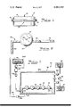
- the filling apparatus is shown diagrammatically, and by way of example only, in FIG. 3.
- the apparatus 34 comprises a hermetically sealable, controllable pressure chamber 36; vacuum means 38; pressure increasing means 40; and electrolyte reservoir 42; electrolyte fill means 44; and electrolyte removal means 46.
- one or more of the cells are placed in rack 26 with the fill port 20 downwardly oriented.
- the rack 26 is then placed in controllable pressure chamber 36 and a cover 36a therefore is suitably locked in position by means not shown.
- the chamber 36 is then evacuated to a high vacuum, about 30" Hg, for a controlled period of time, by vacuum control pump 38 and valve 38a.
- the length of time will vary with the size of the chamber, the capability of the vacuum pump and the number of cells, but should be of sufficient length to remove substantially all water and water vapor from the cells and chamber.
- the vacuum is lessened by increasing the pressure in the chamber 36 to above the boiling point of the electrolyte to be used.
- the vacuum pressure should be about 27" Hg.
- the pressure increase can be accomplished by opening valve 40a which leads to pressure control pump 40 and dispensing into chamber 36 a necessary amount of a dry and inert gas. While dry air can be used, nitrogen or argon or a similar dry and inert gas is preferred.
- a specific amount of electrolyte is dispensed into the bottom of the chamber 36. This specific amount is that necessary to cover the fill port 20 of the cells 10.
- the electrolyte is preferably maintained in a reservoir 42 positioned above chamber 36.
- a metering tank 44 containing the desired amount of electrolyte is positioned between reservoir 42 and chamber 36 and is controlled by a fill valve 44a and an empty valve 44b. With metering tank 44 filled, fill valve 44a is closed and empty valve 44b is opened, thus dispensing a measured amount of electrolyte into chember 36. Empty valve 44b is then closed and fill valve 44a opened to ready metering tank 44 for the next cycle.
- Metering tank 44 is vented to atmosphere at all times somewhere above the level of electrolyte in the reservoir 42.
- vent 52 With the electrolyte removed vent 52 is opened and the chamber 36 vented to atmosphere. Naturally, at this time, all other valves, namely 38a, 40a, 44a, 44b, and 46a are closed.
- the cells are then removed from chamber 36 and positioned with fill ports 20 upwardly oriented to prevent electrolyte leakage to await final sealing.
- Blowing the excess electrolyte from the chamber under pressure reduces the possibility of sucking electrolyte back out of the cells during drainage, as was the case with the prior art techniques.
Abstract
Description
Claims (7)
Priority Applications (3)
| Application Number | Priority Date | Filing Date | Title |
|---|---|---|---|
| US05/703,089 US4061163A (en) | 1976-07-06 | 1976-07-06 | Method of filling electrochemical cells with electrolyte |
| DE19772729034 DE2729034A1 (en) | 1976-07-06 | 1977-06-28 | METHOD OF FILLING ELECTROCHEMICAL CELLS |
| JP7915577A JPS535735A (en) | 1976-07-06 | 1977-07-04 | Method of filling electrolyte in electrochemical cell |
Applications Claiming Priority (1)
| Application Number | Priority Date | Filing Date | Title |
|---|---|---|---|
| US05/703,089 US4061163A (en) | 1976-07-06 | 1976-07-06 | Method of filling electrochemical cells with electrolyte |
Publications (1)
| Publication Number | Publication Date |
|---|---|
| US4061163A true US4061163A (en) | 1977-12-06 |
Family
ID=24823963
Family Applications (1)
| Application Number | Title | Priority Date | Filing Date |
|---|---|---|---|
| US05/703,089 Expired - Lifetime US4061163A (en) | 1976-07-06 | 1976-07-06 | Method of filling electrochemical cells with electrolyte |
Country Status (3)
| Country | Link |
|---|---|
| US (1) | US4061163A (en) |
| JP (1) | JPS535735A (en) |
| DE (1) | DE2729034A1 (en) |
Cited By (21)
| Publication number | Priority date | Publication date | Assignee | Title |
|---|---|---|---|---|
| US5067528A (en) * | 1989-07-19 | 1991-11-26 | Digital Equipment Corporation | Hydrodynamic bearing |
| US5110337A (en) * | 1990-02-28 | 1992-05-05 | Peter Lisec | Method and apparatus for filling the inner space of semifinished insulating glass panels with gas |
| US5141036A (en) * | 1987-07-27 | 1992-08-25 | Semiconductor Energy Laboratory Co., Ltd. | Method of filling a liquid crystal device with introduction of liquid crystal by increasing pressure |
| US5479967A (en) * | 1994-01-24 | 1996-01-02 | B. Braun Medical, Inc. | Method of filling a bourdon tube with a gel substance |
| US5588970A (en) * | 1994-07-06 | 1996-12-31 | Hughett; Elmer | Method for vacuum filling and sealing of a battery cell |
| US5601125A (en) * | 1995-07-18 | 1997-02-11 | Seagate Technology, Inc. | Vacuum fill technique for hydrodynamic bearing |
| US5738690A (en) * | 1994-07-06 | 1998-04-14 | Hughett; Elmer | Method of filling battery cell |
| US6199600B1 (en) * | 1998-11-03 | 2001-03-13 | Samsung Electronics Co., Ltd. | Apparatus for injecting working liquid into micro-injecting device and method for injecting the working liquid |
| US6207318B1 (en) | 1998-06-22 | 2001-03-27 | Eagle-Picher Energy Products Corporation | Electrochemical batteries with restricted liquid electrolyte volume |
| US6305439B1 (en) | 1999-02-25 | 2001-10-23 | Seagate Technology Llc | Vacuum fill/assembly method for fluid dynamic bearing motor |
| WO2002042156A1 (en) * | 2000-11-21 | 2002-05-30 | Amphastar Pharmaceuticals, Incorporated | Process of bulk filling |
| US20020119368A1 (en) * | 2001-02-09 | 2002-08-29 | Tzeng George Tzong-Chyi | Anode structure for metal air electrochemical cells and method of manufacture thereof |
| WO2003001619A2 (en) * | 2001-02-09 | 2003-01-03 | Evionyx, Inc. | Anode structure for metal air electrochemical cells and method of manufacture thereof |
| US6588460B1 (en) | 1999-09-10 | 2003-07-08 | Cmw Automation Gmbh | Device for filling an accumulator cell with electrolyte |
| US20060216577A1 (en) * | 2005-03-28 | 2006-09-28 | Tsan-Hsiung Cheng | Apparatus and method for reposing and reviving a chemical battery |
| WO2009117809A1 (en) * | 2008-03-26 | 2009-10-01 | Hibar Sytems Ltd. | Method of filling electrolyte into battery cell and apparatus for carrying out the method |
| US20090314383A1 (en) * | 2008-06-24 | 2009-12-24 | Ianniello Massimiliano | Plant for electrochemical forming of lead-acid batteries |
| FR2936653A1 (en) * | 2008-09-30 | 2010-04-02 | Commissariat Energie Atomique | LIQUID ELECTROLYTE ACCUMULATOR AND FILLING METHOD |
| US20110017396A1 (en) * | 2008-04-03 | 2011-01-27 | Fujikura Ltd. | Method of manufacturing photoelectric conversion element |
| WO2012069100A1 (en) * | 2010-11-24 | 2012-05-31 | Li-Tec Battery Gmbh | Method and device for filling an electrochemical cell |
| DE102013001576A1 (en) | 2013-01-30 | 2014-07-31 | CMWTEC technologie GmbH | Apparatus and method for filling a cell of an accumulator with electrolyte liquid |
Families Citing this family (1)
| Publication number | Priority date | Publication date | Assignee | Title |
|---|---|---|---|---|
| DE102012211153A1 (en) | 2012-06-28 | 2014-04-10 | Evonik Litarion Gmbh | Self-limiting electrolyte filling method |
Citations (1)
| Publication number | Priority date | Publication date | Assignee | Title |
|---|---|---|---|---|
| US3911972A (en) * | 1971-05-27 | 1975-10-14 | Ernst Hubers | Method of filling containers enclosing solid matter with an accurate amount of liquid |
-
1976
- 1976-07-06 US US05/703,089 patent/US4061163A/en not_active Expired - Lifetime
-
1977
- 1977-06-28 DE DE19772729034 patent/DE2729034A1/en not_active Ceased
- 1977-07-04 JP JP7915577A patent/JPS535735A/en active Pending
Patent Citations (1)
| Publication number | Priority date | Publication date | Assignee | Title |
|---|---|---|---|---|
| US3911972A (en) * | 1971-05-27 | 1975-10-14 | Ernst Hubers | Method of filling containers enclosing solid matter with an accurate amount of liquid |
Cited By (32)
| Publication number | Priority date | Publication date | Assignee | Title |
|---|---|---|---|---|
| US5141036A (en) * | 1987-07-27 | 1992-08-25 | Semiconductor Energy Laboratory Co., Ltd. | Method of filling a liquid crystal device with introduction of liquid crystal by increasing pressure |
| US5067528A (en) * | 1989-07-19 | 1991-11-26 | Digital Equipment Corporation | Hydrodynamic bearing |
| US5110337A (en) * | 1990-02-28 | 1992-05-05 | Peter Lisec | Method and apparatus for filling the inner space of semifinished insulating glass panels with gas |
| US5479967A (en) * | 1994-01-24 | 1996-01-02 | B. Braun Medical, Inc. | Method of filling a bourdon tube with a gel substance |
| US5738690A (en) * | 1994-07-06 | 1998-04-14 | Hughett; Elmer | Method of filling battery cell |
| US5914201A (en) * | 1994-07-06 | 1999-06-22 | Hughett; Elmer | Filling fixture for electric vehicle cell |
| US5588970A (en) * | 1994-07-06 | 1996-12-31 | Hughett; Elmer | Method for vacuum filling and sealing of a battery cell |
| US5601125A (en) * | 1995-07-18 | 1997-02-11 | Seagate Technology, Inc. | Vacuum fill technique for hydrodynamic bearing |
| US6207318B1 (en) | 1998-06-22 | 2001-03-27 | Eagle-Picher Energy Products Corporation | Electrochemical batteries with restricted liquid electrolyte volume |
| US6199600B1 (en) * | 1998-11-03 | 2001-03-13 | Samsung Electronics Co., Ltd. | Apparatus for injecting working liquid into micro-injecting device and method for injecting the working liquid |
| US6305439B1 (en) | 1999-02-25 | 2001-10-23 | Seagate Technology Llc | Vacuum fill/assembly method for fluid dynamic bearing motor |
| US6588460B1 (en) | 1999-09-10 | 2003-07-08 | Cmw Automation Gmbh | Device for filling an accumulator cell with electrolyte |
| WO2002042156A1 (en) * | 2000-11-21 | 2002-05-30 | Amphastar Pharmaceuticals, Incorporated | Process of bulk filling |
| US6418982B1 (en) * | 2000-11-21 | 2002-07-16 | Amphastar Pharmaceuticals Inc. | Process of bulk filling |
| AU2002211780B2 (en) * | 2000-11-21 | 2007-03-01 | Amphastar Pharmaceuticals Incorporated | Process of bulk filling |
| WO2003001619A3 (en) * | 2001-02-09 | 2004-04-08 | Evionyx Inc | Anode structure for metal air electrochemical cells and method of manufacture thereof |
| US20020119368A1 (en) * | 2001-02-09 | 2002-08-29 | Tzeng George Tzong-Chyi | Anode structure for metal air electrochemical cells and method of manufacture thereof |
| WO2003001619A2 (en) * | 2001-02-09 | 2003-01-03 | Evionyx, Inc. | Anode structure for metal air electrochemical cells and method of manufacture thereof |
| US20060216577A1 (en) * | 2005-03-28 | 2006-09-28 | Tsan-Hsiung Cheng | Apparatus and method for reposing and reviving a chemical battery |
| WO2009117809A1 (en) * | 2008-03-26 | 2009-10-01 | Hibar Sytems Ltd. | Method of filling electrolyte into battery cell and apparatus for carrying out the method |
| US20110017396A1 (en) * | 2008-04-03 | 2011-01-27 | Fujikura Ltd. | Method of manufacturing photoelectric conversion element |
| US20090314383A1 (en) * | 2008-06-24 | 2009-12-24 | Ianniello Massimiliano | Plant for electrochemical forming of lead-acid batteries |
| US8286676B2 (en) * | 2008-06-24 | 2012-10-16 | Sovema Usa, Inc. | Plant for electrochemical forming of lead-acid batteries |
| US20110171503A1 (en) * | 2008-09-30 | 2011-07-14 | Commissariat A L'energie Atomique Et Aux Energies Alternatives | Liquid electrolyte storage battery and method for filling |
| WO2010037640A1 (en) * | 2008-09-30 | 2010-04-08 | Commissariat A L'energie Atomique | Liquid-electrolyte storage battery and filling process |
| FR2936653A1 (en) * | 2008-09-30 | 2010-04-02 | Commissariat Energie Atomique | LIQUID ELECTROLYTE ACCUMULATOR AND FILLING METHOD |
| US8568911B2 (en) | 2008-09-30 | 2013-10-29 | Commissariat A L'energie Atomique Et Aux Energies Alternatives | Liquid electrolyte storage battery and method for filling |
| WO2012069100A1 (en) * | 2010-11-24 | 2012-05-31 | Li-Tec Battery Gmbh | Method and device for filling an electrochemical cell |
| DE102013001576A1 (en) | 2013-01-30 | 2014-07-31 | CMWTEC technologie GmbH | Apparatus and method for filling a cell of an accumulator with electrolyte liquid |
| WO2014118057A1 (en) | 2013-01-30 | 2014-08-07 | CMWTEC technologie GmbH | Apparatus and method for filling a cell of a rechargeable battery with electrolyte liquid |
| US20150364746A1 (en) * | 2013-01-30 | 2015-12-17 | CMWTEC technologie GmbH | Apparatus and method for filling a cell of a rechargeable battery with electrolyte liquid |
| US9680146B2 (en) * | 2013-01-30 | 2017-06-13 | CMWTEC technologie GmbH | Apparatus and method for filling a cell of a rechargeable battery with electrolyte liquid |
Also Published As
| Publication number | Publication date |
|---|---|
| DE2729034A1 (en) | 1978-01-12 |
| JPS535735A (en) | 1978-01-19 |
Similar Documents
| Publication | Publication Date | Title |
|---|---|---|
| US4061163A (en) | Method of filling electrochemical cells with electrolyte | |
| US20060260713A1 (en) | Method and apparatus for providing a sealed container containing a detectable gas | |
| US9831531B2 (en) | Method of manufacturing battery | |
| JP5558472B2 (en) | Liquid electrolyte storage battery and method for filling the same | |
| KR100630413B1 (en) | Apparatus and Method for pouring electrolyte | |
| CA2398921A1 (en) | Process of bulk filling | |
| KR100634151B1 (en) | Apparatus for injecting liquid into container and method therefor | |
| GB1510152A (en) | Non-aqueous electrochemical cell | |
| CA2242387A1 (en) | A method and apparatus for applying a treating liquid to a porous body | |
| JP3615699B2 (en) | Sealed battery and method for manufacturing the same | |
| US4913986A (en) | Battery fill-post seal arrangement for hermeticity leakage testing | |
| US6588460B1 (en) | Device for filling an accumulator cell with electrolyte | |
| JP4010477B2 (en) | Apparatus and method for injecting liquid into container | |
| US4542080A (en) | Filling system for hermetically sealed batteries | |
| US4483909A (en) | Electrochemical cell with pressurized liquid electrolyte | |
| JP2002343337A (en) | Method of infusion and draining of electrolytic solution for lithium secondary battery | |
| US4761351A (en) | Battery comprising one or more electrochemical cells having a double-walled cell lid | |
| JP2815880B2 (en) | Impregnation method and equipment | |
| US1969630A (en) | Electrolytic condenser | |
| US4048401A (en) | Hermetically sealed primary electrochemical cell and a method for its production | |
| RU2183371C1 (en) | Metal-air battery | |
| KR20010011573A (en) | Device for pouring electrolyte used in Polymer secondary battery and method for pouring the same | |
| JPS61171061A (en) | Method of pouring electrolyte into cylindrical battery after it is evacuated | |
| JPS63152856A (en) | Electrolyte pouring equipment for storage battery | |
| EP0064511A1 (en) | Method for reducing gas pressure in an electrochemical cell |
Legal Events
| Date | Code | Title | Description |
|---|---|---|---|
| AS | Assignment |
Owner name: WHITTAKER TECHNICAL PRODUCTS, INC., 10880 WILSHIRE Free format text: ASSIGNMENT OF ASSIGNORS INTEREST. SUBJECT TO CONDITIONS RECITED;ASSIGNORS:GTE GOVERNMENT SYSTEMS CORPORATION;GTE LABORATORIES INCORPORATED;REEL/FRAME:004930/0387 Effective date: 19880722 Owner name: WHITTAKER TECHNICAL PRODUCTS, INC., A NY CORP., CA Free format text: ASSIGNMENT OF ASSIGNORS INTEREST;ASSIGNORS:GTE GOVERNMENT SYSTEMS CORPORATION;GTE LABORATORIES INCORPORATED;REEL/FRAME:004930/0387 Effective date: 19880722 |
|
| AS | Assignment |
Owner name: YARDNEY TECHNICAL PRODUCTS, INC., A CORP. OF DE., Free format text: ASSIGNMENT OF ASSIGNORS INTEREST.;ASSIGNOR:WHITTAKER TECHNICAL PRODUCTS, INC., A CORP. OF NY.;REEL/FRAME:005323/0383 Effective date: 19900511 |
|
| AS | Assignment |
Owner name: WHITTAKER TECHNICAL PRODUCTS, INC., A NY CORP. Free format text: RELEASED BY SECURED PARTY;ASSIGNOR:SECURITY PACIFIC NATIONAL BANK;REEL/FRAME:005390/0084 Effective date: 19900511 Owner name: BANK OF NEW YORK, THE Free format text: SECURITY INTEREST;ASSIGNOR:YARDNEY TECHNICAL PRODUCTS, INC., A CORP. OF DE.;REEL/FRAME:005390/0067 Effective date: 19900511 |