US4061380A - Rotational strain relief with inline plug - Google Patents
Rotational strain relief with inline plug Download PDFInfo
- Publication number
- US4061380A US4061380A US05/754,852 US75485276A US4061380A US 4061380 A US4061380 A US 4061380A US 75485276 A US75485276 A US 75485276A US 4061380 A US4061380 A US 4061380A
- Authority
- US
- United States
- Prior art keywords
- tubular member
- bodies
- unit
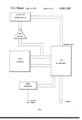
- keyboard
- display
- Prior art date
- Legal status (The legal status is an assumption and is not a legal conclusion. Google has not performed a legal analysis and makes no representation as to the accuracy of the status listed.)
- Expired - Lifetime
Links
Images


Classifications
-
- G—PHYSICS
- G02—OPTICS
- G02B—OPTICAL ELEMENTS, SYSTEMS OR APPARATUS
- G02B6/00—Light guides; Structural details of arrangements comprising light guides and other optical elements, e.g. couplings
- G02B6/10—Light guides; Structural details of arrangements comprising light guides and other optical elements, e.g. couplings of the optical waveguide type
-
- G—PHYSICS
- G06—COMPUTING; CALCULATING OR COUNTING
- G06V—IMAGE OR VIDEO RECOGNITION OR UNDERSTANDING
- G06V10/00—Arrangements for image or video recognition or understanding
- G06V10/98—Detection or correction of errors, e.g. by rescanning the pattern or by human intervention; Evaluation of the quality of the acquired patterns
-
- G—PHYSICS
- G06—COMPUTING; CALCULATING OR COUNTING
- G06V—IMAGE OR VIDEO RECOGNITION OR UNDERSTANDING
- G06V30/00—Character recognition; Recognising digital ink; Document-oriented image-based pattern recognition
- G06V30/10—Character recognition
- G06V30/14—Image acquisition
- G06V30/142—Image acquisition using hand-held instruments; Constructional details of the instruments
-
- H—ELECTRICITY
- H01—ELECTRIC ELEMENTS
- H01R—ELECTRICALLY-CONDUCTIVE CONNECTIONS; STRUCTURAL ASSOCIATIONS OF A PLURALITY OF MUTUALLY-INSULATED ELECTRICAL CONNECTING ELEMENTS; COUPLING DEVICES; CURRENT COLLECTORS
- H01R35/00—Flexible or turnable line connectors, i.e. the rotation angle being limited
- H01R35/02—Flexible line connectors without frictional contact members
-
- G—PHYSICS
- G02—OPTICS
- G02B—OPTICAL ELEMENTS, SYSTEMS OR APPARATUS
- G02B6/00—Light guides; Structural details of arrangements comprising light guides and other optical elements, e.g. couplings
- G02B2006/0098—Light guides; Structural details of arrangements comprising light guides and other optical elements, e.g. couplings for scanning
Definitions
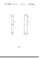
- FIG. 8 is a pictoral view of the light pipe used to transmit the cotnrol signal to and from the writ document;
- the light pipe illustrated is made by injection molding with acrylic plastic.
- the light pipe is a homogeneous material as opposed to individual glass fibers.
- the mold In order to impart a mirror finish to the sides of the light pipe the mold has a 16 microinch finish or better.
- One advantage of this type of light pipe is that only one inexpensive part is needed to perform the function.
Abstract
Description
              Table 1
______________________________________
Serial Message Format F-8 to TMS 1200
Character/Function MSB        LSB
______________________________________
0                  1000       0000
1                  1000       0001
2                  1000       0010
3                  1000       0011
4                  1000       0100
5                  1000       0101
6                  1000       0110
7                  1000       0111
8                  1000       1000
9                  1000       1001
--                 1000       1010
A                  1000       1011
F                  1000       1100
E                  1000       1101
C                  1000       1110
 (Blank)           1000       1111
 End of Message    1001       XXXX
 Recall 1          1010       XXXX
 Recall 2          1010       XXXX
Hold Message in TMS 1200
                   1100       1111
Release Hold       1100       0000
Force Attn Key     1101       1111
Release "Attn" Key Force
                   1101       0000
Blink Display      1110       XXXX
Clear Display      1111       XXXX
X=Don't Care
______________________________________
              Table 2
______________________________________
Serial Message Format From TMS 1200 to F-8
Key Number   MSB           LSB
______________________________________
1            0000          0000
2            0000          0001
3            0000          0010
4            0000          0011
5            0000          0100
6            0000          0101
7            0000          0110
8            0000          0111
9            0000          1000
10           0000          1001
11           0000          1010
12           0000          1011
13           0000          1100
14           0000          1101
15           0000          1110
ATTN         1111          1111
2nd Level    1111          1110
3rd Level    1111          1101
______________________________________
Claims (7)
Priority Applications (12)
| Application Number | Priority Date | Filing Date | Title |
|---|---|---|---|
| US05/754,852 US4061380A (en) | 1976-12-27 | 1976-12-27 | Rotational strain relief with inline plug |
| GB49621/77A GB1591447A (en) | 1976-12-27 | 1977-11-29 | Optical character recognition system |
| NL7713609A NL7713609A (en) | 1976-12-27 | 1977-12-08 | OPTICAL CHARACTER RECOGNITION SYSTEM WITH MANUAL INPUT UNIT. |
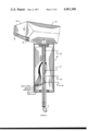
| CA293,378A CA1089945A (en) | 1976-12-27 | 1977-12-19 | Tubular structure for rotationally interconnecting two bodies, both mechanically and electrically |
| DK575977A DK575977A (en) | 1976-12-27 | 1977-12-22 | OPTICAL DRAWING SYSTEM WITH HAND READER |
| SE7714672A SE7714672L (en) | 1976-12-27 | 1977-12-22 | OPTICAL TEXT READER WITH SCANNING HAND PROBE AND BERBAR ELECTRONICS |
| DE19772757495 DE2757495A1 (en) | 1976-12-27 | 1977-12-22 | OPTICAL CHARACTER RECOGNITION SYSTEM |
| NO774431A NO774431L (en) | 1976-12-27 | 1977-12-22 | DEVICE FOR OPTICAL DRAWING RECOGNITION |
| FR7739075A FR2375666A1 (en) | 1976-12-27 | 1977-12-23 | OPTICAL CHARACTER READING DEVICE |
| JP15662977A JPS5389628A (en) | 1976-12-27 | 1977-12-27 | Optical character recognizing device* full data entry unit* mutual connector* and photoconductor |
| JP1982120663U JPS5840435Y2 (en) | 1976-12-27 | 1982-08-10 | Portable optical character recognition device |
| JP1982120662U JPS5840434Y2 (en) | 1976-12-27 | 1982-08-10 | Portable optical character recognition device |
Applications Claiming Priority (1)
| Application Number | Priority Date | Filing Date | Title |
|---|---|---|---|
| US05/754,852 US4061380A (en) | 1976-12-27 | 1976-12-27 | Rotational strain relief with inline plug |
Publications (1)
| Publication Number | Publication Date |
|---|---|
| US4061380A true US4061380A (en) | 1977-12-06 |
Family
ID=25036637
Family Applications (1)
| Application Number | Title | Priority Date | Filing Date |
|---|---|---|---|
| US05/754,852 Expired - Lifetime US4061380A (en) | 1976-12-27 | 1976-12-27 | Rotational strain relief with inline plug |
Country Status (2)
| Country | Link |
|---|---|
| US (1) | US4061380A (en) |
| CA (1) | CA1089945A (en) |
Cited By (11)
| Publication number | Priority date | Publication date | Assignee | Title |
|---|---|---|---|---|
| US4414546A (en) * | 1979-10-16 | 1983-11-08 | Robert G. Boorman | Apparatus for and methods of identifying horses by scanning their chestnuts |
| US4472010A (en) * | 1983-01-31 | 1984-09-18 | Parnello Nicholas G | Twist-inhibiting appliance for connecting a cable of a telephone set or the like |
| US4716291A (en) * | 1984-05-16 | 1987-12-29 | Matsushita Electric Industrial Co., Ltd. | Copying machine |
| US4772954A (en) * | 1984-03-01 | 1988-09-20 | Matsushita Electric Industrial Co., Ltd. | Copying machine |
| US4800444A (en) * | 1986-02-05 | 1989-01-24 | Alps Electric Co., Ltd. | Image scanner |
| US5130520A (en) * | 1982-01-25 | 1992-07-14 | Symbol Technologies, Inc. | Narrow-bodied, single- and twin-windowed portable laser scanning head for reading bar code symbols |
| US5467458A (en) * | 1991-05-21 | 1995-11-14 | Sharp Kabushiki Kaisha | Optical character reader with internal memory and data processor |
| US5532469A (en) * | 1982-01-25 | 1996-07-02 | Symbol Technologies, Inc. | Hand held bar code reader with input and display device and processor |
| US6149062A (en) * | 1988-01-14 | 2000-11-21 | Intermec Ip Corp. | Interface with hand-held data capture terminal, proximity and label sensing, and enhanced sensitivity and power efficiency |
| US6232973B1 (en) * | 1998-08-07 | 2001-05-15 | Hewlett-Packard Company | Appliance and method for navigating among multiple captured images and functional menus |
| US20020005747A1 (en) * | 2000-07-11 | 2002-01-17 | Mitsubishi Denki Kabushiki Kaisha | Semiconductor device with signal transfer line |
Citations (2)
| Publication number | Priority date | Publication date | Assignee | Title |
|---|---|---|---|---|
| US3550061A (en) * | 1968-01-08 | 1970-12-22 | Eugene G Sukup | Electrical swivel connector |
| US3947817A (en) * | 1974-01-07 | 1976-03-30 | Recognition Equipment Incorporated | Hand operated optical character recognition wand |
-
1976
- 1976-12-27 US US05/754,852 patent/US4061380A/en not_active Expired - Lifetime
-
1977
- 1977-12-19 CA CA293,378A patent/CA1089945A/en not_active Expired
Patent Citations (2)
| Publication number | Priority date | Publication date | Assignee | Title |
|---|---|---|---|---|
| US3550061A (en) * | 1968-01-08 | 1970-12-22 | Eugene G Sukup | Electrical swivel connector |
| US3947817A (en) * | 1974-01-07 | 1976-03-30 | Recognition Equipment Incorporated | Hand operated optical character recognition wand |
Cited By (11)
| Publication number | Priority date | Publication date | Assignee | Title |
|---|---|---|---|---|
| US4414546A (en) * | 1979-10-16 | 1983-11-08 | Robert G. Boorman | Apparatus for and methods of identifying horses by scanning their chestnuts |
| US5130520A (en) * | 1982-01-25 | 1992-07-14 | Symbol Technologies, Inc. | Narrow-bodied, single- and twin-windowed portable laser scanning head for reading bar code symbols |
| US5532469A (en) * | 1982-01-25 | 1996-07-02 | Symbol Technologies, Inc. | Hand held bar code reader with input and display device and processor |
| US4472010A (en) * | 1983-01-31 | 1984-09-18 | Parnello Nicholas G | Twist-inhibiting appliance for connecting a cable of a telephone set or the like |
| US4772954A (en) * | 1984-03-01 | 1988-09-20 | Matsushita Electric Industrial Co., Ltd. | Copying machine |
| US4716291A (en) * | 1984-05-16 | 1987-12-29 | Matsushita Electric Industrial Co., Ltd. | Copying machine |
| US4800444A (en) * | 1986-02-05 | 1989-01-24 | Alps Electric Co., Ltd. | Image scanner |
| US6149062A (en) * | 1988-01-14 | 2000-11-21 | Intermec Ip Corp. | Interface with hand-held data capture terminal, proximity and label sensing, and enhanced sensitivity and power efficiency |
| US5467458A (en) * | 1991-05-21 | 1995-11-14 | Sharp Kabushiki Kaisha | Optical character reader with internal memory and data processor |
| US6232973B1 (en) * | 1998-08-07 | 2001-05-15 | Hewlett-Packard Company | Appliance and method for navigating among multiple captured images and functional menus |
| US20020005747A1 (en) * | 2000-07-11 | 2002-01-17 | Mitsubishi Denki Kabushiki Kaisha | Semiconductor device with signal transfer line |
Also Published As
| Publication number | Publication date |
|---|---|
| CA1089945A (en) | 1980-11-18 |
Similar Documents
| Publication | Publication Date | Title |
|---|---|---|
| US4158194A (en) | Optical recognition system | |
| US4128298A (en) | Wand nose with integral light pipe for wand power turn-on | |
| US4850009A (en) | Portable handheld terminal including optical bar code reader and electromagnetic transceiver means for interactive wireless communication with a base communications station | |
| US5047615A (en) | Bar code printing or reading apparatus | |
| US4061380A (en) | Rotational strain relief with inline plug | |
| US5198650A (en) | Hands free/hand held bar code scanner | |
| CA1252891A (en) | Portable programmable optical code reader | |
| US4935610A (en) | Hand-held bar code reader | |
| US4621189A (en) | Hand held data entry apparatus | |
| EP0262943B1 (en) | Portable data scanner apparatus | |
| EP0094571B1 (en) | Self-contained portable data entry terminal | |
| US5675139A (en) | Interface arrangement for use with consumer devices | |
| CA1268253A (en) | Portable handheld terminal including optical bar code reader and electromagnetic transceiver | |
| US5664229A (en) | Accessory for conversion with housing with first connection includes host cable and host connector and second connection including a plug-in modular connector | |
| US8235291B2 (en) | PDA compatible text scanner | |
| US20050150959A1 (en) | Optical reader | |
| GB1591447A (en) | Optical character recognition system | |
| US5745794A (en) | System for converting signals into a predetermined data exchange format with plug-in modular connector having voltage, ground, data, and clock terminals for a scanning head | |
| US8474720B2 (en) | PDA compatible text scanner | |
| US4782513A (en) | Voice prompted bar code reading satellite system | |
| JPH0363781A (en) | Laser scanning system for reading bar code | |
| JPS6132443Y2 (en) | ||
| TW457446B (en) | Integrated keyboard input device | |
| JPH01213763A (en) | Portable data terminal equipment | |
| JP2000222519A (en) | Optical information read and communication device, reader, communication device |
Legal Events
| Date | Code | Title | Description |
|---|---|---|---|
| AS | Assignment |
Owner name: CHEMICAL BANK, A NY BANKING CORP. Free format text: SECURITY INTEREST;ASSIGNORS:RECOGNITION EQUIPMENT INCORPORATED;PLEXUS SOFTWARE, INC.;REEL/FRAME:005323/0509 Effective date: 19891119 |
|
| AS | Assignment |
Owner name: RECOGNITION EQUIPMENT INCORPORATED ("REI") 2701 EA Free format text: RELEASED BY SECURED PARTY;ASSIGNOR:CHEMICAL BANK, A NY. BANKING CORP.;REEL/FRAME:005439/0823 Effective date: 19900731 |
|
| AS | Assignment |
Owner name: FIRST NATIONAL BANK OF BOSTON, THE, AS AGENT, MASS Free format text: SECURITY INTEREST;ASSIGNORS:RECOGNITION EQUIPMENT INC.;HYBRID SYSTEMS, INC.;RECOGNITION EQUIPMENT (JAPAN), INC.;REEL/FRAME:006344/0298 Effective date: 19920326 |
|
| AS | Assignment |
Owner name: RECOGNITION INTERNATIONAL INC., TEXAS Free format text: CHANGE OF NAME;ASSIGNOR:RECOGNITION EQUIPMENT INCORPORATED;REEL/FRAME:006462/0646 Effective date: 19930312 |