US4210957A - Operating optimization for plural parallel connected chillers - Google Patents
Operating optimization for plural parallel connected chillers Download PDFInfo
- Publication number
- US4210957A US4210957A US05/904,170 US90417078A US4210957A US 4210957 A US4210957 A US 4210957A US 90417078 A US90417078 A US 90417078A US 4210957 A US4210957 A US 4210957A
- Authority
- US
- United States
- Prior art keywords
- capacity
- refrigerant
- head
- refrigerant head
- chillers
- Prior art date
- Legal status (The legal status is an assumption and is not a legal conclusion. Google has not performed a legal analysis and makes no representation as to the accuracy of the status listed.)
- Expired - Lifetime
Links
- 238000005457 optimization Methods 0.000 title claims abstract description 18
- 239000003507 refrigerant Substances 0.000 claims abstract description 123
- 238000005057 refrigeration Methods 0.000 claims abstract description 16
- 238000000034 method Methods 0.000 claims 5
- XLYOFNOQVPJJNP-UHFFFAOYSA-N water Substances O XLYOFNOQVPJJNP-UHFFFAOYSA-N 0.000 description 11
- 238000001816 cooling Methods 0.000 description 3
- 230000007423 decrease Effects 0.000 description 2
- 238000004378 air conditioning Methods 0.000 description 1
- 238000010586 diagram Methods 0.000 description 1
- 239000013589 supplement Substances 0.000 description 1
Images


Classifications
-
- F—MECHANICAL ENGINEERING; LIGHTING; HEATING; WEAPONS; BLASTING
- F24—HEATING; RANGES; VENTILATING
- F24F—AIR-CONDITIONING; AIR-HUMIDIFICATION; VENTILATION; USE OF AIR CURRENTS FOR SCREENING
- F24F11/00—Control or safety arrangements
- F24F11/70—Control systems characterised by their outputs; Constructional details thereof
- F24F11/80—Control systems characterised by their outputs; Constructional details thereof for controlling the temperature of the supplied air
- F24F11/83—Control systems characterised by their outputs; Constructional details thereof for controlling the temperature of the supplied air by controlling the supply of heat-exchange fluids to heat-exchangers
- F24F11/84—Control systems characterised by their outputs; Constructional details thereof for controlling the temperature of the supplied air by controlling the supply of heat-exchange fluids to heat-exchangers using valves
-
- G—PHYSICS
- G05—CONTROLLING; REGULATING
- G05D—SYSTEMS FOR CONTROLLING OR REGULATING NON-ELECTRIC VARIABLES
- G05D23/00—Control of temperature
- G05D23/19—Control of temperature characterised by the use of electric means
- G05D23/1917—Control of temperature characterised by the use of electric means using digital means
-
- G—PHYSICS
- G05—CONTROLLING; REGULATING
- G05D—SYSTEMS FOR CONTROLLING OR REGULATING NON-ELECTRIC VARIABLES
- G05D23/00—Control of temperature
- G05D23/19—Control of temperature characterised by the use of electric means
- G05D23/20—Control of temperature characterised by the use of electric means with sensing elements having variation of electric or magnetic properties with change of temperature
-
- F—MECHANICAL ENGINEERING; LIGHTING; HEATING; WEAPONS; BLASTING
- F25—REFRIGERATION OR COOLING; COMBINED HEATING AND REFRIGERATION SYSTEMS; HEAT PUMP SYSTEMS; MANUFACTURE OR STORAGE OF ICE; LIQUEFACTION SOLIDIFICATION OF GASES
- F25B—REFRIGERATION MACHINES, PLANTS OR SYSTEMS; COMBINED HEATING AND REFRIGERATION SYSTEMS; HEAT PUMP SYSTEMS
- F25B2400/00—General features or devices for refrigeration machines, plants or systems, combined heating and refrigeration systems or heat-pump systems, i.e. not limited to a particular subgroup of F25B
- F25B2400/06—Several compression cycles arranged in parallel
-
- F—MECHANICAL ENGINEERING; LIGHTING; HEATING; WEAPONS; BLASTING
- F25—REFRIGERATION OR COOLING; COMBINED HEATING AND REFRIGERATION SYSTEMS; HEAT PUMP SYSTEMS; MANUFACTURE OR STORAGE OF ICE; LIQUEFACTION SOLIDIFICATION OF GASES
- F25B—REFRIGERATION MACHINES, PLANTS OR SYSTEMS; COMBINED HEATING AND REFRIGERATION SYSTEMS; HEAT PUMP SYSTEMS
- F25B2700/00—Sensing or detecting of parameters; Sensors therefor
- F25B2700/21—Temperatures
- F25B2700/2116—Temperatures of a condenser
- F25B2700/21161—Temperatures of a condenser of the fluid heated by the condenser
-
- F—MECHANICAL ENGINEERING; LIGHTING; HEATING; WEAPONS; BLASTING
- F25—REFRIGERATION OR COOLING; COMBINED HEATING AND REFRIGERATION SYSTEMS; HEAT PUMP SYSTEMS; MANUFACTURE OR STORAGE OF ICE; LIQUEFACTION SOLIDIFICATION OF GASES
- F25B—REFRIGERATION MACHINES, PLANTS OR SYSTEMS; COMBINED HEATING AND REFRIGERATION SYSTEMS; HEAT PUMP SYSTEMS
- F25B2700/00—Sensing or detecting of parameters; Sensors therefor
- F25B2700/21—Temperatures
- F25B2700/2117—Temperatures of an evaporator
- F25B2700/21171—Temperatures of an evaporator of the fluid cooled by the evaporator
- F25B2700/21172—Temperatures of an evaporator of the fluid cooled by the evaporator at the inlet
-
- F—MECHANICAL ENGINEERING; LIGHTING; HEATING; WEAPONS; BLASTING
- F25—REFRIGERATION OR COOLING; COMBINED HEATING AND REFRIGERATION SYSTEMS; HEAT PUMP SYSTEMS; MANUFACTURE OR STORAGE OF ICE; LIQUEFACTION SOLIDIFICATION OF GASES
- F25B—REFRIGERATION MACHINES, PLANTS OR SYSTEMS; COMBINED HEATING AND REFRIGERATION SYSTEMS; HEAT PUMP SYSTEMS
- F25B2700/00—Sensing or detecting of parameters; Sensors therefor
- F25B2700/21—Temperatures
- F25B2700/2117—Temperatures of an evaporator
- F25B2700/21171—Temperatures of an evaporator of the fluid cooled by the evaporator
- F25B2700/21173—Temperatures of an evaporator of the fluid cooled by the evaporator at the outlet
Definitions
- This invention relates to optimally switching chillers into and out of a refrigeration system in a building, and, more particularly, controlling the switching of these chillers as a function of at least the design refrigerant head and the actual refrigerant head of the chillers.
- the chillers are switched as a function of, not only design refrigerant head and actual refrigerant head, but also minimum refrigerant head, the capacity of the refrigerating system at the design refrigerant head and the capacity of the refrigerating system at minimum refrigerant head.
- refrigeration systems having a plurality of chillers. It is apparent that in such systems comprising more than one chillers, it becomes necessary to decide how many chillers to use based upon present conditions and when additional chillers should be connected to or disconnected from the refrigeration system.
- Prior art systems were rudimentary in their approach to switching between plural chillers to satisfy the refrigeration needs of the building. If they were not simply switched into and out of the refrigeration system manually according to need, simple systems based upon actual building loads were used.
- such a simple system comprised three chillers, for example, and if the actual building load was less than 33% one chiller was operated in the refrigeration system; but if the actual building load exceeded 33% of the total design capacity of the three chillers, two chillers were operated and all three chillers were operated if the actual building load exceeded 66% of the total design chiller capacity. If the actual building load dropped below the 66% capacity, the third chiller was disconnected and, if the actual building load dropped below the 33% capacity the second chiller was disconnected.
- chiller controls do not optimize chiller performance, however, and do not conserve on the electrical energy needed to drive the chillers for providing refrigeration because the arbitrary 33% and 66% switchover points do not reflect optimized performance and may result in chillers being switched on or off when extra capacity is available from the machines operating just prior to switching.
- the system according to the present invention provides a more sophisticated system for determining the number of chillers which should be operated at any given time. The decision for switching is based upon actual conditions and the most efficient switchover points rather than switching chillers based upon a fixed percentage of total design capacity.
- the present optimization system for switching between plural chillers in a plural chiller refrigeration system comprises an apparatus for measuring the load capacity which the building represents, determining the optimized switchover capacity based upon at least the design refrigerant head and the actual refrigerant head and for switching in additional chillers when the actual building load exceeds the optimized switchover capacity and for disconnecting chillers when the actual building load decreases below the switchover capacity of the chillers.
- FIG. 1 is a diagram showing the refrigeration system and the control system for operating the chillers in the system
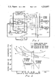
- FIG. 2 is a graph showing horsepower/ton and refrigeration head versus the percent of the total design capacity of the refrigeration system
- FIG. 3 is a graph of an isolated portion of the graph of FIG. 2;
- FIGS. 4 and 5 show a flowchart of the program which can be used with the computer shown in FIG. 1 to control the chillers.
- loads 11 and 12 which may represent zones in a building are supplied with a refrigerant such as chilled water from supply line 13 through respective valves 14 and 15.
- supply line 13 supplies chilled water to the other loads in the building.
- Chilled water is returned from loads 11 and 12 and the other loads of a building through return line 16 and is circulated through the chiller system by pumps 17 and 18.
- the pumps 17 and 18 pump the chilled water back through valves 21 and 22 to respective chillers 23 and 24.
- the chillers chill the water and supply the chilled water to supply line 13 through their respective output lines 25 and 26.
- condenser water may be circulated through chillers 23 and 24 by pump 31 and lines 32 and 33 to cooling tower 34 to exhaust building heat.
- chillers 23 and 24 are controlled by computer 41 which derives inputs from thermostat 42 sensing the temperature of the water being returned from the cooling tower 34, thermostat 43 for sensing the temperature of the refrigerant in supply line 13, thermostat 44 for sensing the temperature of the refrigerant in return line 16 and flow sensor 45 which senses the flow rate of the refrigerant in the refrigerating system.
- Thermostats 42, 43 and 44 may be Honeywell L7092 Temperature Sensor and flow sensor 45 may be a Honeywell P760 Pressure Difference Sensor.
- the computer 41 determines that chiller 23 should be connected into the system, it sends a signal over output line 51 to open valve 21 and to start chiller 23 by way of starting motor 52.
- computer 41 determines that chiller 24 should be connected into the refrigerating system to supplement chiller 23 it supplies a signal over line 54 to starting motor 55 to start up chiller 24 and also to valve 22 to open it and allow refrigerant to be circulated through chiller 24.
- FIGS. 2 and 3 show how the program which is used in computer 41 to control chillers 23 and 24 was derived.
- curve A represents the horsepower per ton characteristic of one chiller as a function of load at design refrigerant head.
- Curve B represents the horsepower per ton characteristic of the chiller as a function of load at minimum refrigerant head.
- Curve C represents the horsepower per ton characteristic of two parallel connected chillers as a function of load at design refrigerant head and curve D represents the horsepower per ton characteristic of two parallel connected chillers as a function of load at minimum refrigerant head.
- Curves E and F are similar curves but for three parallel connected chillers.
- the second chiller was started by prior art systems when the building load exceeded 33% of the total design capacity for three chillers.
- the third chiller was started. Going back the other way, when building load dropped below 66% of the design capacity for three chillers, the third chiller was disconnected from the system. As the building load continued to decrease and fell below 33% of the design capacity of the three-chiller system, the second chiller was disconnected from the system.
- this mode of operation does not best utilize the energy necessary to drive the chillers for refrigerating the building.
- the optimum point for switching between one and two chillers as shown by curve A is when all of the capacity of the one chiller is used.
- the chiller is operating at its minimum refrigerant head, the optimum point to switch over to the second chiller as shown by curve B is at the end of the capacity of the first chiller.
- the graph on the lower portion of FIG. 2 shows the line extending from the optimized switchover point at design head to the optimized switchover point at minimum refrigerant head. The actual refrigerant head will be somewhere between these two extreme points along the optimized changeover line and can be used to determine the optimized switchover capacity.
- the optimum switchover point is at the intersection of curves C and E.
- the optimized changeover point is at the end of the capacity of two chillers.
- the optimized chiller line extends from the intersection of curves C and E at design refrigerant head to the end of the capacities of two chillers at minimum refrigerant head.
- the actual refrigerant head will be somewhere along this optimized changeover line and can be used to determine the optimized switchover capacity.
- the shaded areas of FIG. 2 represent the potential saving when switching according to the optimized changeover graph as shown in FIG. 2 as opposed to the conventional switching known in the prior art.
- equation 1 becomes
- Equation 7 can be factored to yield the following equation: ##EQU6##
- Equation (12) therefore gives the optimized switchover capacity as a function of actual refrigerant head for switching between two chillers.
- the only variable in the equation is the refrigerant head, the other terms, C, K3 and HRM being constants and determined by the particular chillers selected for the refrigerating system shown in FIG. 1.
- the computer in FIG. 1 now computes the actual building load in terms of capacity and compares the actual building load to the optimized switchover capacity as derived by equation (12) and will connect in the second chiller if the building load exceeds the optimized switchover capacity and will disconnect the second chiller if the actual building load falls below the optimized switchover capacity.
- Equation K4 The slope for this equation, K4, can be given by the expression ##EQU9## where F is the capacity of two machines at minimum refrigerant head, E is the capacity of two machines at design refrigerant head, HRD is the design refrigerant head and HRM is the minimum refrigerant head. Constant K4 is a fixed value depending upon chiller parameters and equation (13) has only one variable, HD, which is the actual chiller head of the chiller system.
- the computer by using sensors 43, 44 and 45 determines actual head, HD, and uses the value of the actual head in equations (12) and (13) to determine the optimized switchover capacities for optimally switching between chillers.
- the computer also uses these sensors to determine actual building load in terms of capacity so that the actual building load can be compared to the optimum switchover capacity.
- the computer 41 uses the inputs from sensors 43, 44 and 45 as inputs to equations 12, 13 and 15 which input to the program shown in FIGS. 4 and 5 for controlling chillers 23 and 24 by way of output lines 51 and 54.
- the program is entered periodically, for example every minute.
- the first step of the program in FIG. 4 is to determine whether both chillers are off. If both chillers are off, if the outdoor air temperature is above 50° and if the fans of the refrigeration system are on, chiller 1 will be started if it is in the lead position and chiller 2 will be started if chiller 1 is not in the lead position.
- the determination of which chiller is in the lead position is a manual switch operation to determine which chiller should be turned on first and disconnected last.
- the fans may be turned on by an optimized start/stop program or device which are known in the art and which turn on the fans in the morning as a function of both time and outdoor temperature and turn the fans off at night as a function of time.
- At least one chiller is running as long as the fans are on and the outdoor temperature is above 50°. If the outdoor air temperature is below 50°, or if the fans are not on, no chillers will be started and the program will exit to re-enter again a predetermined length of time later.
- both chillers are not off. If after entering the program, it is determined that both chillers are not off, a test is made to determined whether both chillers are on. If both chillers are not on, then only one chiller is on and a test is made to determined whether the fans are on. If the fans are not on, and if chiller 1 is on, chiller 1 will be turned off. If the fans are not on and chiller 1 is not on, chiller 2 must be on and it will be turned off. No chillers should be operating when the fans are off. If the fans are on, it is next determined whether the building load in terms of capacity is greater than the optimized switchover capacity as determined by solving equation (12). If the actual building load is not greater than the optimized switchover capacity, no additional chiller need be switched in and the program exits.
- chiller 1 If the actual building load capacity is greater than the optimized switchover capacity, another chiller must be started. To determine which chiller should be started, a test is made to determine whether chiller 1 is on. If chiller 1 is not on, then chiller 2 must be on, but if chiller 2 has not been on for twenty minutes, it is not desirable to add chiller 1 at this time. Therefore, the program exits to wait for the passage of twenty minutes. After chiller 2 has been on for twenty minutes, a test determines whether or not chiller 1 has been off for fifteen minutes. A chiller should not be restarted until it has been off for at least fifteen minutes. If chiller 1 has not been off for fifteen minutes, the program exits to wait for the passage of fifteen minutes. If chiller 1 has been off for fifteen minutes, it is started.
- chiller 1 is the chiller that was on, and chiller 2 off, a determination is made whether chiller 1 has been on for twenty minutes. If not, the program exits to wait twenty minutes. If it has, it is next determined whether chiller 2 has been off for fifteen minutes. If it has not, the program exits to wait the passage of fifteen minutes. If it has, chiller 2 is started.
- the program proceeds to point A of FIG. 5 where a determination is made whether or not the fans are on. If the fans are not on, then both chillers must be stopped. If the fans are on, a test is made to determine whether the actual building load in terms of capacity is less than the optimized switchover capacity as determined by the solution of equation (12) minus a small differential of 0.01. If the actual building load is not less than this optimized switchover capacity, the program exits. If it is, then one of the chillers should be turned off. Thus, if the chiller 1 is the lead chiller, a test is made to determine whether chiller 2 has been on for fifteen minutes. If it has, it will be turned off; and if it has not, the program will exit to await the passage of fifteen minutes. If the chiller 1 is not the lead chiller, then a test is made to determine whether chiller 2 has been on for fifteen minutes. If it has, it is turned off; if it has not, the program exits to await the passage of 15 minutes.
- FIGS. 4 and 5 will control the switching on and off of the chillers according to the optimal mode for so doing.
- the flowcharts of FIGS. 4 and 5 together with the equations disclosed herein are sufficient to enable a programmer to program the DELTA 1000 computer to carry out the invention, however as an additional aid the programmer may wish to refer to Honeywell publication Form No. 74-1157 entitled ALPHA/DELTA 1000 control interpreter language basic theory.
- the flow charts only cover two chillers and it is apparent that, if more chillers are added, the program must be expanded. Also, building load is given by the equation
- TR is the temperature of the return chilled water (15)
- TS is the temperature of the supply chilled water
- P is the orifice pressure difference sensed by sensor 45
- Kp is the flow orifice constant
Landscapes
- Engineering & Computer Science (AREA)
- Chemical & Material Sciences (AREA)
- Combustion & Propulsion (AREA)
- Mechanical Engineering (AREA)
- General Engineering & Computer Science (AREA)
- Physics & Mathematics (AREA)
- General Physics & Mathematics (AREA)
- Automation & Control Theory (AREA)
- Air Conditioning Control Device (AREA)
Abstract
An optimization system for switching between plural parallel connected chillers in a refrigeration system is disclosed which system establishes optimized changeover criteria based upon the design refrigerant head for the chillers, the minimum refrigerant head for the chillers, the capacity of the chillers at design head and the capacity of the chillers at minimum head, and which system, using these criteria, calculates optimized switchover capacity as a function of the present actual refrigerant head. The system then compares the optimized switchover capacity to the present building load and, if the capacity is insufficient to meet the building load, an additional chiller is switched in and, if the optimized switchover capacity is greater than the building load and more than one chiller is operating, one of the chillers is disconnected.
Description
This invention relates to optimally switching chillers into and out of a refrigeration system in a building, and, more particularly, controlling the switching of these chillers as a function of at least the design refrigerant head and the actual refrigerant head of the chillers. To increase efficiency, the chillers are switched as a function of, not only design refrigerant head and actual refrigerant head, but also minimum refrigerant head, the capacity of the refrigerating system at the design refrigerant head and the capacity of the refrigerating system at minimum refrigerant head.
In order to meet the air-conditioning needs of large commercial buildings, refrigeration systems are provided having a plurality of chillers. It is apparent that in such systems comprising more than one chillers, it becomes necessary to decide how many chillers to use based upon present conditions and when additional chillers should be connected to or disconnected from the refrigeration system. Prior art systems were rudimentary in their approach to switching between plural chillers to satisfy the refrigeration needs of the building. If they were not simply switched into and out of the refrigeration system manually according to need, simple systems based upon actual building loads were used. If such a simple system comprised three chillers, for example, and if the actual building load was less than 33% one chiller was operated in the refrigeration system; but if the actual building load exceeded 33% of the total design capacity of the three chillers, two chillers were operated and all three chillers were operated if the actual building load exceeded 66% of the total design chiller capacity. If the actual building load dropped below the 66% capacity, the third chiller was disconnected and, if the actual building load dropped below the 33% capacity the second chiller was disconnected. These types of chiller controls do not optimize chiller performance, however, and do not conserve on the electrical energy needed to drive the chillers for providing refrigeration because the arbitrary 33% and 66% switchover points do not reflect optimized performance and may result in chillers being switched on or off when extra capacity is available from the machines operating just prior to switching. The system according to the present invention provides a more sophisticated system for determining the number of chillers which should be operated at any given time. The decision for switching is based upon actual conditions and the most efficient switchover points rather than switching chillers based upon a fixed percentage of total design capacity.
The present optimization system for switching between plural chillers in a plural chiller refrigeration system comprises an apparatus for measuring the load capacity which the building represents, determining the optimized switchover capacity based upon at least the design refrigerant head and the actual refrigerant head and for switching in additional chillers when the actual building load exceeds the optimized switchover capacity and for disconnecting chillers when the actual building load decreases below the switchover capacity of the chillers.
These and other features and advantages will become apparent from a detailed consideration of the invention when taken in conjunction with the drawings in which:
FIG. 1 is a diagram showing the refrigeration system and the control system for operating the chillers in the system;
FIG. 2 is a graph showing horsepower/ton and refrigeration head versus the percent of the total design capacity of the refrigeration system;
FIG. 3 is a graph of an isolated portion of the graph of FIG. 2; and,
FIGS. 4 and 5 show a flowchart of the program which can be used with the computer shown in FIG. 1 to control the chillers.
In FIG. 1, loads 11 and 12 which may represent zones in a building are supplied with a refrigerant such as chilled water from supply line 13 through respective valves 14 and 15. In addition, supply line 13 supplies chilled water to the other loads in the building. Chilled water is returned from loads 11 and 12 and the other loads of a building through return line 16 and is circulated through the chiller system by pumps 17 and 18. The pumps 17 and 18 pump the chilled water back through valves 21 and 22 to respective chillers 23 and 24. The chillers chill the water and supply the chilled water to supply line 13 through their respective output lines 25 and 26. In addition, condenser water may be circulated through chillers 23 and 24 by pump 31 and lines 32 and 33 to cooling tower 34 to exhaust building heat. Thus, the heat of the building which is returned by the water in return line 16 to chillers 23 and 24 by pumps 17 and 18 is expelled from the building by use of cooling tower 34. Starting and stopping of chillers 23 and 24 as well as opening and closing of valves 21 and 22 are controlled by computer 41 which derives inputs from thermostat 42 sensing the temperature of the water being returned from the cooling tower 34, thermostat 43 for sensing the temperature of the refrigerant in supply line 13, thermostat 44 for sensing the temperature of the refrigerant in return line 16 and flow sensor 45 which senses the flow rate of the refrigerant in the refrigerating system. Thermostats 42, 43 and 44 may be Honeywell L7092 Temperature Sensor and flow sensor 45 may be a Honeywell P760 Pressure Difference Sensor. When the computer 41 determines that chiller 23 should be connected into the system, it sends a signal over output line 51 to open valve 21 and to start chiller 23 by way of starting motor 52. Likewise, when computer 41 determines that chiller 24 should be connected into the refrigerating system to supplement chiller 23 it supplies a signal over line 54 to starting motor 55 to start up chiller 24 and also to valve 22 to open it and allow refrigerant to be circulated through chiller 24.
FIGS. 2 and 3 show how the program which is used in computer 41 to control chillers 23 and 24 was derived. In FIG. 2, curve A represents the horsepower per ton characteristic of one chiller as a function of load at design refrigerant head. Curve B represents the horsepower per ton characteristic of the chiller as a function of load at minimum refrigerant head. Curve C represents the horsepower per ton characteristic of two parallel connected chillers as a function of load at design refrigerant head and curve D represents the horsepower per ton characteristic of two parallel connected chillers as a function of load at minimum refrigerant head. Curves E and F are similar curves but for three parallel connected chillers.
As discussed above, in a three-chiller system, the second chiller was started by prior art systems when the building load exceeded 33% of the total design capacity for three chillers. When the building load exceeded 66% of the design capacity of the three chillers, the third chiller was started. Going back the other way, when building load dropped below 66% of the design capacity for three chillers, the third chiller was disconnected from the system. As the building load continued to decrease and fell below 33% of the design capacity of the three-chiller system, the second chiller was disconnected from the system.
As can be seen from FIG. 2, this mode of operation does not best utilize the energy necessary to drive the chillers for refrigerating the building. If the system is operating at its design refrigerant head, the optimum point for switching between one and two chillers as shown by curve A is when all of the capacity of the one chiller is used. If the chiller is operating at its minimum refrigerant head, the optimum point to switch over to the second chiller as shown by curve B is at the end of the capacity of the first chiller. Thus, the graph on the lower portion of FIG. 2 shows the line extending from the optimized switchover point at design head to the optimized switchover point at minimum refrigerant head. The actual refrigerant head will be somewhere between these two extreme points along the optimized changeover line and can be used to determine the optimized switchover capacity.
In switching from two chillers to three chillers at design head, the optimum switchover point is at the intersection of curves C and E. At minimum refrigerant head, the optimized changeover point is at the end of the capacity of two chillers. Thus, the optimized chiller line extends from the intersection of curves C and E at design refrigerant head to the end of the capacities of two chillers at minimum refrigerant head. Again, the actual refrigerant head will be somewhere along this optimized changeover line and can be used to determine the optimized switchover capacity.
The shaded areas of FIG. 2 represent the potential saving when switching according to the optimized changeover graph as shown in FIG. 2 as opposed to the conventional switching known in the prior art.
The changeover curves of FIG. 2 have been reproduced in FIG. 3 as an aid in determining the equation for calculating the optimized switchover capacity for determining when the switchover between machines should occur. The general equation for defining the types of curves shown in FIG. 3 can be given by the general equation
Y=K1(X-K2)
In the terms of the graph shown in FIG. 3, equation 1 becomes
HD=K1(CAP-K2). (2)
where HD is the refrigerant head and CAP is capacity. The slope, K1, can be given by the equation ##EQU1## where HRD is the design refrigerant head for one chiller, HRM is the minimum refrigerant head for one chiller, B1 is the capacity of one chiller at design refrigerant head, and C is the capacity of one chiller at minimum refrigerant head. Substituting equation (3) into equation (2), equation (2) becomes ##EQU2## From equation (4), K2 can be given by the following expression: ##EQU3## In order to solve equation (5) to determine the value for the constant K2, the point on the changeover curve between one and two chillers represented by the minimum refrigerant head can be substituted in equation (5). Specifically, C is substituted for the term CAP and HRM is substituted for the term HD which yields the following value for K2: ##EQU4## Inserting K2 into equation (4), the actual refrigerant head is then given by ##EQU5## Equation 7 can be factored to yield the following equation: ##EQU6## By changing signs in equation (8), the following equation can be derived: ##EQU7## If we introduce a third constant to our formula given by the following expression ##EQU8## and, multiplying through by the constant K3, equation (9) becomes
(K3) (HD)=C-CAP+(HRM) (K3) (11)
which reduces down to the following equation:
CAP=C-K3(HD-HRM). (12)
Equation (12) therefore gives the optimized switchover capacity as a function of actual refrigerant head for switching between two chillers. The only variable in the equation is the refrigerant head, the other terms, C, K3 and HRM being constants and determined by the particular chillers selected for the refrigerating system shown in FIG. 1. The computer in FIG. 1 now computes the actual building load in terms of capacity and compares the actual building load to the optimized switchover capacity as derived by equation (12) and will connect in the second chiller if the building load exceeds the optimized switchover capacity and will disconnect the second chiller if the actual building load falls below the optimized switchover capacity.
Similarly, if three machines are used in a refrigeration system such as the one shown in FIG. 1, the optimized changeover capacity curve between two and three chillers can be given by the equation
CAP=F-[(HD-HRM)K4]. (13)
The slope for this equation, K4, can be given by the expression ##EQU9## where F is the capacity of two machines at minimum refrigerant head, E is the capacity of two machines at design refrigerant head, HRD is the design refrigerant head and HRM is the minimum refrigerant head. Constant K4 is a fixed value depending upon chiller parameters and equation (13) has only one variable, HD, which is the actual chiller head of the chiller system.
The computer, by using sensors 43, 44 and 45 determines actual head, HD, and uses the value of the actual head in equations (12) and (13) to determine the optimized switchover capacities for optimally switching between chillers. The computer also uses these sensors to determine actual building load in terms of capacity so that the actual building load can be compared to the optimum switchover capacity. The computer 41 uses the inputs from sensors 43, 44 and 45 as inputs to equations 12, 13 and 15 which input to the program shown in FIGS. 4 and 5 for controlling chillers 23 and 24 by way of output lines 51 and 54.
In FIGS. 4 and 5, the program is entered periodically, for example every minute. The first step of the program in FIG. 4 is to determine whether both chillers are off. If both chillers are off, if the outdoor air temperature is above 50° and if the fans of the refrigeration system are on, chiller 1 will be started if it is in the lead position and chiller 2 will be started if chiller 1 is not in the lead position. The determination of which chiller is in the lead position is a manual switch operation to determine which chiller should be turned on first and disconnected last. The fans may be turned on by an optimized start/stop program or device which are known in the art and which turn on the fans in the morning as a function of both time and outdoor temperature and turn the fans off at night as a function of time. In this manner, at least one chiller is running as long as the fans are on and the outdoor temperature is above 50°. If the outdoor air temperature is below 50°, or if the fans are not on, no chillers will be started and the program will exit to re-enter again a predetermined length of time later.
If after entering the program, it is determined that both chillers are not off, a test is made to determined whether both chillers are on. If both chillers are not on, then only one chiller is on and a test is made to determined whether the fans are on. If the fans are not on, and if chiller 1 is on, chiller 1 will be turned off. If the fans are not on and chiller 1 is not on, chiller 2 must be on and it will be turned off. No chillers should be operating when the fans are off. If the fans are on, it is next determined whether the building load in terms of capacity is greater than the optimized switchover capacity as determined by solving equation (12). If the actual building load is not greater than the optimized switchover capacity, no additional chiller need be switched in and the program exits. If the actual building load capacity is greater than the optimized switchover capacity, another chiller must be started. To determine which chiller should be started, a test is made to determine whether chiller 1 is on. If chiller 1 is not on, then chiller 2 must be on, but if chiller 2 has not been on for twenty minutes, it is not desirable to add chiller 1 at this time. Therefore, the program exits to wait for the passage of twenty minutes. After chiller 2 has been on for twenty minutes, a test determines whether or not chiller 1 has been off for fifteen minutes. A chiller should not be restarted until it has been off for at least fifteen minutes. If chiller 1 has not been off for fifteen minutes, the program exits to wait for the passage of fifteen minutes. If chiller 1 has been off for fifteen minutes, it is started.
If chiller 1 is the chiller that was on, and chiller 2 off, a determination is made whether chiller 1 has been on for twenty minutes. If not, the program exits to wait twenty minutes. If it has, it is next determined whether chiller 2 has been off for fifteen minutes. If it has not, the program exits to wait the passage of fifteen minutes. If it has, chiller 2 is started.
If both chillers have been on, the program proceeds to point A of FIG. 5 where a determination is made whether or not the fans are on. If the fans are not on, then both chillers must be stopped. If the fans are on, a test is made to determine whether the actual building load in terms of capacity is less than the optimized switchover capacity as determined by the solution of equation (12) minus a small differential of 0.01. If the actual building load is not less than this optimized switchover capacity, the program exits. If it is, then one of the chillers should be turned off. Thus, if the chiller 1 is the lead chiller, a test is made to determine whether chiller 2 has been on for fifteen minutes. If it has, it will be turned off; and if it has not, the program will exit to await the passage of fifteen minutes. If the chiller 1 is not the lead chiller, then a test is made to determine whether chiller 2 has been on for fifteen minutes. If it has, it is turned off; if it has not, the program exits to await the passage of 15 minutes.
As can be seen, the program flowchart shown in FIGS. 4 and 5 will control the switching on and off of the chillers according to the optimal mode for so doing. The flowcharts of FIGS. 4 and 5 together with the equations disclosed herein are sufficient to enable a programmer to program the DELTA 1000 computer to carry out the invention, however as an additional aid the programmer may wish to refer to Honeywell publication Form No. 74-1157 entitled ALPHA/DELTA 1000 control interpreter language basic theory. The flow charts only cover two chillers and it is apparent that, if more chillers are added, the program must be expanded. Also, building load is given by the equation
Load=Kp√ΔP (TR-TS)
where TR is the temperature of the return chilled water (15), TS is the temperature of the supply chilled water, P is the orifice pressure difference sensed by sensor 45, and Kp is the flow orifice constant.
Claims (17)
1. An optimization system for switching between at least first and second parallel connected chillers of a plural chiller refrigeration system, said chillers having an optimized range of changeover capacities defined at one end by an optimized changeover capacity at design refrigerant head of said first chiller and at the other end by an optimized changeover capacity at minimum refrigerant head of the first chiller, said optimization system comprising:
first means for supplying signals from which the actual load capacity of said building can be determined;
second means for supplying signals from which the actual refrigerant head of said chillers can be determined; and,
third means responsive to said first and second means for determining said actual load capacity, said actual refrigerant head, an optimized switchover capacity based upon said actual refrigerant head, said design refrigerant head, said minimum refrigerant head, said optimized changeover capacity at said design refrigerant head and said optimized changeover capacity at said minimum refrigerant head, and for comparing said optimized switchover capacity to said actual load capacity to switch on both chillers when said actual load capacity exceeds said optimized switchover capacity and to switch off one of said chillers when said actual load capacity falls below said optimized switchover capacity.
2. The optimization system of claim 1 wherein said first means comprises a first temperature sensor for sensing the temperature of refrigerant leaving said chillers, a second temperature sensor for sensing the temperature of refrigerant entering said chillers and flow sensing means for sensing the flow rate of said refrigerant.
3. The optimization system of claim 2 wherein said second means comprises said first and second temperature sensors for providing said actual refrigerant head.
4. The optimization system of claim 3 wherein said third means comprises means for determining the optimized switchover capacity by the following equation
CAP=C-K3(HD-HRM)
where C is the capacity of one chiller at minimum refrigerant head, HD is the actual refrigerant head, HRM is the minimum refrigerant head and K3 is given by the equation ##EQU10## where HRD is the design refrigerant head and B1 is the capacity of one machine at design refrigerant head.
5. The optimization system of claim 4 wherein said third means further comprises output lines connecting said third means to said first and second chillers.
6. The optimization system of claim 1 wherein said second means comprises first and second temperature sensors for sensing the temperature of supply and return refrigerant and providing said actual refrigerant head.
7. The optimization system of claim 6 wherein said third means comprises means for determining the optimized switchover capacity by the equation
CAP=C-K3(HD-HRM)
where C is the capacity of one chiller at minimum refrigerant head, HD is the actual refrigerant head, HRM is the minimum refrigerant head and K3 is given by the equation ##EQU11## where HRD is the design refrigerant head and B1 is the capacity of one chiller at design refrigerant head.
8. The optimization system of claim 7 wherein said third means further comprises output lines connecting said third means to said first and second chillers.
9. The optimization system of claim 1 wherein said third means comprises means for determining the optimized switchover capacity by the equation
CAP=C-K3(HD-HRM)
where C is the capacity of one chiller at minimum refrigerant head, HD is the actual refrigerant head, HRM is the minimum refrigerant head and K3 is given by the equation ##EQU12## where HRD is the design refrigerant head and B1 is the capacity of one machine at design refrigerant head.
10. An optimization system for switching between at least first and second parallel connected chillers of a plural chiller refrigeration system, said chillers circulating a refrigerant to said building, said chillers having an optimized range of changeover capacities defined at one end by an optimized changeover capacity at design refrigerant head of said first chiller and at the other end by an optimized changeover capacity at minimum refrigerant head of the first chiller, said optimization system comprising:
a first temperature sensor for sensing the temperature of said refrigerant supplied to said building;
a second temperature sensor for sensing the temperature of said refrigerant being returned to said chillers from the building;
a flow sensor for sensing the flow rate of said refrigerant; and,
control means connected to said first and second temperature sensors and to said flow sensor for determining actual load requirements in terms of capacity for said building for determining actual refrigerant head and for determining an optimized switchover capacity based upon said actual refrigerant head, said design refrigerant head, said minimum refrigerant head, said optimized changeover capacity at said design refrigerant head and said optimized changeover capacity at said minimum refrigerant head, said control means including means for switching on an additional chiller when said actual building load in terms of capacity exceeds said optimized switchover capacity and for switching off a chiller when said building load in terms of capacity falls below said optimized switchover changeover capacity.
11. The optimization system of claim 10 wherein said control means comprises first means for determining said actual load in terms of capacity of said building, second means for determining said optimized switchover capacity based upon said actual refrigerant head, said design refrigerant head, said minimum refrigerant head, said optimized changeover capacity at said design refrigerant head, and said optimized changeover capacity at said minimum refrigerant head, and comparing means for comparing said actual load in terms of capacity with said optimized switchover capacity.
12. The optimization system of claim 11 wherein said second means comprises means for determining the optimized switchover capacity by the equation
CAP=C-K3(HD-HRM)
where C is the capacity of one chiller at minimum refrigerant head, HD is the actual refrigerant head, HRM is the minimum refrigerant head and K3 is given by the equation ##EQU13## where HRD is the design refrigerant head and B1 is the capacity of one machine at design refrigerant head.
13. The optimization system of claim 10 wherein said control means comprises means for determining the optimized switchover capacity by the equation
CAP=C-K3(HD-HRM)
where C is the capacity of one chiller at minimum refrigerant head, HD is the actual refrigerant head, HRM is the minimum refrigerant head and K3 is given by the equation ##EQU14## where HRD is the design refrigerant head and B1 is the capacity of one machine at design refrigerant head.
14. A method for optimally switching on and off chillers in a parallel connected plural chiller refrigerant system, said chillers having an optimized range of changeover capacity defined at one end by an optimized changeover capacity at design refrigerant head and at the other end by an optimized changeover capacity at minimum refrigerant head, said method comprising the steps of:
determining actual load of said building in terms of capacity;
determining actual refrigerant head for said chillers;
determining an optimized switchover capacity based upon actual refrigerant head, design refrigerant head, minimum refrigerant head, optimized changeover capacity at design refrigerant head, and optimized changeover capacity at minimum refrigerant head;
comparing the actual load in terms of capacity and the optimized switchover capacity; and,
switching on an additional chiller when the actual load in terms of capacity exceeds the optimized switchover capacity and switching off a chiller when the actual load in terms of capacity falls below the optimized switchover capacity.
15. The method of claim 14 wherein the step of measuring the actual load capacity comprises the further steps of:
measuring the temperature of refrigerant leaving said chillers;
measuring the temperature of refrigerant entering said chillers; and,
measuring the flow rate of the refrigerant being circulated by the chillers.
16. The method of claim 15 wherein the step of determining actual refrigerant head comprises the steps of:
measuring the temperature of refrigerant leaving said chillers; and,
measuring the temperature of refrigerant entering said chillers.
17. The method of claim 16 wherein actual refrigerant head is determined by subtracting the temperature of the supplied refrigerant from the temperature of the returned refrigerant and wherein the step of determining the optimized switchover capacity is determined by using the actual refrigerant head to solve the equation
CAP=C-K3(HD-HRM)
where C is the capacity of one machine at minimum refrigerant head, HD is the actual refrigerant head, HRM is the minimum refrigerant head and K3 is given by the equation ##EQU15## where HRD is the design refrigerant head and B1 is the capacity of one machine at minimum refrigerant head.
Priority Applications (2)
| Application Number | Priority Date | Filing Date | Title |
|---|---|---|---|
| US05/904,170 US4210957A (en) | 1978-05-08 | 1978-05-08 | Operating optimization for plural parallel connected chillers |
| CA325,600A CA1093304A (en) | 1978-05-08 | 1979-04-17 | Operating optimization for plural parallel connected chillers |
Applications Claiming Priority (1)
| Application Number | Priority Date | Filing Date | Title |
|---|---|---|---|
| US05/904,170 US4210957A (en) | 1978-05-08 | 1978-05-08 | Operating optimization for plural parallel connected chillers |
Publications (1)
| Publication Number | Publication Date |
|---|---|
| US4210957A true US4210957A (en) | 1980-07-01 |
Family
ID=25418702
Family Applications (1)
| Application Number | Title | Priority Date | Filing Date |
|---|---|---|---|
| US05/904,170 Expired - Lifetime US4210957A (en) | 1978-05-08 | 1978-05-08 | Operating optimization for plural parallel connected chillers |
Country Status (2)
| Country | Link |
|---|---|
| US (1) | US4210957A (en) |
| CA (1) | CA1093304A (en) |
Cited By (51)
| Publication number | Priority date | Publication date | Assignee | Title |
|---|---|---|---|---|
| US4368502A (en) * | 1981-05-05 | 1983-01-11 | Barber-Colman Company | Lead-lag load lockout control |
| FR2518227A1 (en) * | 1981-12-15 | 1983-06-17 | Coremaex | Chilled water plant for air conditioning - has auxiliary circuit by=passing refrigeration plant controlled by thermostatic valves |
| US4463574A (en) * | 1982-03-15 | 1984-08-07 | Honeywell Inc. | Optimized selection of dissimilar chillers |
| US4483152A (en) * | 1983-07-18 | 1984-11-20 | Butler Manufacturing Company | Multiple chiller control method |
| US4487028A (en) * | 1983-09-22 | 1984-12-11 | The Trane Company | Control for a variable capacity temperature conditioning system |
| FR2580060A1 (en) * | 1985-04-05 | 1986-10-10 | Nec Corp | |
| US4633672A (en) * | 1985-02-19 | 1987-01-06 | Margaux Controls, Inc. | Unequal compressor refrigeration control system |
| US4655277A (en) * | 1984-04-27 | 1987-04-07 | Phillips Petroleum Company | Process control for parallel heat exchangers |
| US4716740A (en) * | 1986-04-14 | 1988-01-05 | Hayes John H | Controller apparatus and method for heat exchange system |
| US4726893A (en) * | 1984-04-27 | 1988-02-23 | Phillips Petroleum Company | Catalytic crackins process control |
| US4747912A (en) * | 1984-04-27 | 1988-05-31 | Phillips Petroleum Company | Cracking furnace control |
| DE3716259A1 (en) * | 1987-05-15 | 1988-11-24 | Eckardt Ag | Method for regulating a process variable of an industrial process applied to two or more consumers that can be switched in or out, in particular for the pressure regulation of a burner or heating system |
| US4852362A (en) * | 1984-07-24 | 1989-08-01 | Multistack, Inc. | Modular refrigeration system |
| US4926649A (en) * | 1987-06-11 | 1990-05-22 | Martinez Jr George | Method and apparatus for saving energy in an air conditioning system |
| EP0396600A1 (en) * | 1988-01-19 | 1990-11-14 | Multistack Int Pty Ltd | Improvements in heating and cooling systems. |
| WO1993003311A1 (en) * | 1991-08-06 | 1993-02-18 | Cassowary Limited | Temperature control apparatus and a central unit for temperature control apparatus |
| US5195329A (en) * | 1991-11-12 | 1993-03-23 | Carrier Corporation | Automatic chiller plant balancing |
| US5222370A (en) * | 1992-01-17 | 1993-06-29 | Carrier Corporation | Automatic chiller stopping sequence |
| US5724825A (en) * | 1996-09-11 | 1998-03-10 | Mosel Vitelic Inc. | Automatic temperature controlling system |
| US6185946B1 (en) | 1999-05-07 | 2001-02-13 | Thomas B. Hartman | System for sequencing chillers in a loop cooling plant and other systems that employ all variable-speed units |
| US6666042B1 (en) | 2002-07-01 | 2003-12-23 | American Standard International Inc. | Sequencing of variable primary flow chiller system |
| US6718779B1 (en) | 2001-12-11 | 2004-04-13 | William R. Henry | Method to optimize chiller plant operation |
| US20040068996A1 (en) * | 2002-10-14 | 2004-04-15 | Lyman Tseng | [automatic control system of liquid chillers] |
| US20050039904A1 (en) * | 2003-08-20 | 2005-02-24 | Aler Mark Dennis | Fluid heat exchange control system |
| US20050189430A1 (en) * | 2004-02-26 | 2005-09-01 | Mestek, Inc. | Multi-zone integral face bypass coil system |
| US20050223723A1 (en) * | 2004-04-12 | 2005-10-13 | York International Corporation | Startup control system and method for a multiple compressor chiller system |
| US20070056300A1 (en) * | 2004-04-12 | 2007-03-15 | Johnson Controls Technology Company | System and method for capacity control in a multiple compressor chiller system |
| EP1766304A2 (en) * | 2004-06-24 | 2007-03-28 | Carrier Corporation | Free cooling activation optimized controls |
| US20070107449A1 (en) * | 2004-04-12 | 2007-05-17 | York International Corporation | System and method for capacity control in a multiple compressor chiller system |
| US20090020173A1 (en) * | 2006-02-23 | 2009-01-22 | David Man Chu Lau | Industrial process efficiency method and system |
| US20100198409A1 (en) * | 2009-02-02 | 2010-08-05 | Hartman Thomas B | Sequencing of variable speed compressors in a chilled liquid cooling system for improved energy efficiency |
| ITBO20090313A1 (en) * | 2009-05-15 | 2010-11-16 | Rhoss S P A | METHOD AND SYSTEM TO CHECK A PLURALITY OF REFRIGERATING MACHINES OF A CLIMATE CONTROL SYSTEM |
| EP2253897A1 (en) * | 2009-05-15 | 2010-11-24 | Rhoss S.p.A. | Method and system for controlling a plurality of refrigerating machines |
| US20100307171A1 (en) * | 2009-06-06 | 2010-12-09 | International Business Machines Corporation | Cooling Infrastructure Leveraging a Combination of Free and Solar Cooling |
| US20100326098A1 (en) * | 2008-03-12 | 2010-12-30 | Rog Lynn M | Cooling, heating and power system with an integrated part-load, active, redundant chiller |
| US20110030916A1 (en) * | 2008-02-07 | 2011-02-10 | Stiwa Holding Gmbh | Method for optimizing thermal energy current guidance |
| US7894943B2 (en) | 2005-06-30 | 2011-02-22 | Sloup Charles J | Real-time global optimization of building setpoints and sequence of operation |
| CN101688701B (en) * | 2007-07-18 | 2011-08-17 | 三菱电机株式会社 | Refrigerating cycle device and method for controlling operation of the same |
| US20120198872A1 (en) * | 2009-10-28 | 2012-08-09 | Mitsubishi Electric Corporation | Air-conditioning apparatus |
| US20120204585A1 (en) * | 2009-10-28 | 2012-08-16 | Mitsubishi Electric Corporation | Air-conditioning apparatus |
| US20120304675A1 (en) * | 2010-02-10 | 2012-12-06 | Mitsubishi Electric Corporation | Air-conditioning apparatus |
| US8453469B1 (en) * | 2007-09-28 | 2013-06-04 | Exaflop Llc | Changing data center cooling modes |
| US20130283829A1 (en) * | 2012-04-25 | 2013-10-31 | Basf Se | Method for providing a refrigerant medium in a secondary cycle |
| US20140216068A1 (en) * | 2013-02-01 | 2014-08-07 | Lg Electronics Inc. | Chiller system and control method thereof |
| CN104654525A (en) * | 2015-02-02 | 2015-05-27 | 珠海格力电器股份有限公司 | Air conditioner host machine increase and decrease control method and device as well as air conditioner system |
| US20150211762A1 (en) * | 2012-09-26 | 2015-07-30 | Daikin Industries, Ltd. | Heat source system control device |
| US20150362268A1 (en) * | 2013-01-18 | 2015-12-17 | Calsonic Kansei Corporation | Cooling medium circulating apparatus, air conditioning apparatus for vehicle, and method for controlling cooling medium circulating apparatus |
| US20160054034A1 (en) * | 2014-08-22 | 2016-02-25 | Lg Electronics Inc. | Chiller system |
| JP2016205814A (en) * | 2016-08-08 | 2016-12-08 | ダイキン工業株式会社 | Load distribution system |
| US10760840B2 (en) | 2015-11-09 | 2020-09-01 | Carrier Corporation | Dual-compressor refrigeration unit |
| US20210285719A1 (en) * | 2020-03-13 | 2021-09-16 | Air Products And Chemicals, Inc. | Heat exchanger apparatus, manifold arrangement for a heat exchanger apparatus, and methods relating to same |
Citations (6)
| Publication number | Priority date | Publication date | Assignee | Title |
|---|---|---|---|---|
| US3400374A (en) * | 1965-06-16 | 1968-09-03 | Robertshaw Controls Co | Computerized control systems |
| US3555251A (en) * | 1967-12-06 | 1971-01-12 | Honeywell Inc | Optimizing system for a plurality of temperature conditioning apparatuses |
| US3875995A (en) * | 1971-08-17 | 1975-04-08 | Gerald F Mannion | Process fluid flow primary and secondary regulation systems |
| US3995443A (en) * | 1975-01-02 | 1976-12-07 | Iversen Rudolf O | Air conditioning system |
| US4084388A (en) * | 1976-11-08 | 1978-04-18 | Honeywell Inc. | Refrigeration control system for optimum demand operation |
| US4122893A (en) * | 1977-03-07 | 1978-10-31 | American Air Filter Company, Inc. | Air conditioning system |
-
1978
- 1978-05-08 US US05/904,170 patent/US4210957A/en not_active Expired - Lifetime
-
1979
- 1979-04-17 CA CA325,600A patent/CA1093304A/en not_active Expired
Patent Citations (6)
| Publication number | Priority date | Publication date | Assignee | Title |
|---|---|---|---|---|
| US3400374A (en) * | 1965-06-16 | 1968-09-03 | Robertshaw Controls Co | Computerized control systems |
| US3555251A (en) * | 1967-12-06 | 1971-01-12 | Honeywell Inc | Optimizing system for a plurality of temperature conditioning apparatuses |
| US3875995A (en) * | 1971-08-17 | 1975-04-08 | Gerald F Mannion | Process fluid flow primary and secondary regulation systems |
| US3995443A (en) * | 1975-01-02 | 1976-12-07 | Iversen Rudolf O | Air conditioning system |
| US4084388A (en) * | 1976-11-08 | 1978-04-18 | Honeywell Inc. | Refrigeration control system for optimum demand operation |
| US4122893A (en) * | 1977-03-07 | 1978-10-31 | American Air Filter Company, Inc. | Air conditioning system |
Cited By (70)
| Publication number | Priority date | Publication date | Assignee | Title |
|---|---|---|---|---|
| US4368502A (en) * | 1981-05-05 | 1983-01-11 | Barber-Colman Company | Lead-lag load lockout control |
| FR2518227A1 (en) * | 1981-12-15 | 1983-06-17 | Coremaex | Chilled water plant for air conditioning - has auxiliary circuit by=passing refrigeration plant controlled by thermostatic valves |
| US4463574A (en) * | 1982-03-15 | 1984-08-07 | Honeywell Inc. | Optimized selection of dissimilar chillers |
| US4483152A (en) * | 1983-07-18 | 1984-11-20 | Butler Manufacturing Company | Multiple chiller control method |
| US4487028A (en) * | 1983-09-22 | 1984-12-11 | The Trane Company | Control for a variable capacity temperature conditioning system |
| US4726893A (en) * | 1984-04-27 | 1988-02-23 | Phillips Petroleum Company | Catalytic crackins process control |
| US4655277A (en) * | 1984-04-27 | 1987-04-07 | Phillips Petroleum Company | Process control for parallel heat exchangers |
| US4747912A (en) * | 1984-04-27 | 1988-05-31 | Phillips Petroleum Company | Cracking furnace control |
| US4852362A (en) * | 1984-07-24 | 1989-08-01 | Multistack, Inc. | Modular refrigeration system |
| US4633672A (en) * | 1985-02-19 | 1987-01-06 | Margaux Controls, Inc. | Unequal compressor refrigeration control system |
| FR2580060A1 (en) * | 1985-04-05 | 1986-10-10 | Nec Corp | |
| US4729424A (en) * | 1985-04-05 | 1988-03-08 | Nec Corporation | Cooling system for electronic equipment |
| US4716740A (en) * | 1986-04-14 | 1988-01-05 | Hayes John H | Controller apparatus and method for heat exchange system |
| DE3716259A1 (en) * | 1987-05-15 | 1988-11-24 | Eckardt Ag | Method for regulating a process variable of an industrial process applied to two or more consumers that can be switched in or out, in particular for the pressure regulation of a burner or heating system |
| US4926649A (en) * | 1987-06-11 | 1990-05-22 | Martinez Jr George | Method and apparatus for saving energy in an air conditioning system |
| EP0396600A4 (en) * | 1988-01-19 | 1992-03-18 | Multistack International Pty. Ltd. | Improvements in heating and cooling systems |
| EP0396600A1 (en) * | 1988-01-19 | 1990-11-14 | Multistack Int Pty Ltd | Improvements in heating and cooling systems. |
| WO1993003311A1 (en) * | 1991-08-06 | 1993-02-18 | Cassowary Limited | Temperature control apparatus and a central unit for temperature control apparatus |
| US5195329A (en) * | 1991-11-12 | 1993-03-23 | Carrier Corporation | Automatic chiller plant balancing |
| US5222370A (en) * | 1992-01-17 | 1993-06-29 | Carrier Corporation | Automatic chiller stopping sequence |
| US5724825A (en) * | 1996-09-11 | 1998-03-10 | Mosel Vitelic Inc. | Automatic temperature controlling system |
| US6185946B1 (en) | 1999-05-07 | 2001-02-13 | Thomas B. Hartman | System for sequencing chillers in a loop cooling plant and other systems that employ all variable-speed units |
| US6718779B1 (en) | 2001-12-11 | 2004-04-13 | William R. Henry | Method to optimize chiller plant operation |
| US6666042B1 (en) | 2002-07-01 | 2003-12-23 | American Standard International Inc. | Sequencing of variable primary flow chiller system |
| US20040068996A1 (en) * | 2002-10-14 | 2004-04-15 | Lyman Tseng | [automatic control system of liquid chillers] |
| US20050039904A1 (en) * | 2003-08-20 | 2005-02-24 | Aler Mark Dennis | Fluid heat exchange control system |
| US7028768B2 (en) * | 2003-08-20 | 2006-04-18 | Itt Manufacturing Enterprises, Inc. | Fluid heat exchange control system |
| US20050189430A1 (en) * | 2004-02-26 | 2005-09-01 | Mestek, Inc. | Multi-zone integral face bypass coil system |
| US20050223723A1 (en) * | 2004-04-12 | 2005-10-13 | York International Corporation | Startup control system and method for a multiple compressor chiller system |
| US20070056300A1 (en) * | 2004-04-12 | 2007-03-15 | Johnson Controls Technology Company | System and method for capacity control in a multiple compressor chiller system |
| US7793509B2 (en) | 2004-04-12 | 2010-09-14 | Johnson Controls Technology Company | System and method for capacity control in a multiple compressor chiller system |
| US20070107449A1 (en) * | 2004-04-12 | 2007-05-17 | York International Corporation | System and method for capacity control in a multiple compressor chiller system |
| US7231773B2 (en) | 2004-04-12 | 2007-06-19 | York International Corporation | Startup control system and method for a multiple compressor chiller system |
| US7661274B2 (en) | 2004-04-12 | 2010-02-16 | York International Corporation | System and method for capacity control in a multiple compressor chiller system |
| EP1766304A4 (en) * | 2004-06-24 | 2009-11-11 | Carrier Corp | Free cooling activation optimized controls |
| EP1766304A2 (en) * | 2004-06-24 | 2007-03-28 | Carrier Corporation | Free cooling activation optimized controls |
| US7894943B2 (en) | 2005-06-30 | 2011-02-22 | Sloup Charles J | Real-time global optimization of building setpoints and sequence of operation |
| US9032748B2 (en) * | 2006-02-23 | 2015-05-19 | David Man Chu Lau | Industrial fluid circuits and method of controlling the industrial fluid circuits using variable speed drives on the fluid pumps of the industrial fluid circuits |
| US20090020173A1 (en) * | 2006-02-23 | 2009-01-22 | David Man Chu Lau | Industrial process efficiency method and system |
| US10107283B2 (en) | 2006-02-23 | 2018-10-23 | David Man Chu Lau | Industrial fluid circuits and method of controlling the industrial fluid circuits using variable speed drives on the fluid pumps of the industrial fluid circuits |
| CN101688701B (en) * | 2007-07-18 | 2011-08-17 | 三菱电机株式会社 | Refrigerating cycle device and method for controlling operation of the same |
| US8453469B1 (en) * | 2007-09-28 | 2013-06-04 | Exaflop Llc | Changing data center cooling modes |
| US20110030916A1 (en) * | 2008-02-07 | 2011-02-10 | Stiwa Holding Gmbh | Method for optimizing thermal energy current guidance |
| US20100326098A1 (en) * | 2008-03-12 | 2010-12-30 | Rog Lynn M | Cooling, heating and power system with an integrated part-load, active, redundant chiller |
| US8291720B2 (en) | 2009-02-02 | 2012-10-23 | Optimum Energy, Llc | Sequencing of variable speed compressors in a chilled liquid cooling system for improved energy efficiency |
| US20100198409A1 (en) * | 2009-02-02 | 2010-08-05 | Hartman Thomas B | Sequencing of variable speed compressors in a chilled liquid cooling system for improved energy efficiency |
| EP2253897A1 (en) * | 2009-05-15 | 2010-11-24 | Rhoss S.p.A. | Method and system for controlling a plurality of refrigerating machines |
| ITBO20090313A1 (en) * | 2009-05-15 | 2010-11-16 | Rhoss S P A | METHOD AND SYSTEM TO CHECK A PLURALITY OF REFRIGERATING MACHINES OF A CLIMATE CONTROL SYSTEM |
| US20100307171A1 (en) * | 2009-06-06 | 2010-12-09 | International Business Machines Corporation | Cooling Infrastructure Leveraging a Combination of Free and Solar Cooling |
| US8020390B2 (en) * | 2009-06-06 | 2011-09-20 | International Business Machines Corporation | Cooling infrastructure leveraging a combination of free and solar cooling |
| US9335074B2 (en) * | 2009-10-28 | 2016-05-10 | Mitsubishi Electric Corporation | Air-conditioning apparatus |
| US9303904B2 (en) * | 2009-10-28 | 2016-04-05 | Mitsubishi Electric Corporation | Air-conditioning apparatus |
| US20120198872A1 (en) * | 2009-10-28 | 2012-08-09 | Mitsubishi Electric Corporation | Air-conditioning apparatus |
| US20120204585A1 (en) * | 2009-10-28 | 2012-08-16 | Mitsubishi Electric Corporation | Air-conditioning apparatus |
| US20120304675A1 (en) * | 2010-02-10 | 2012-12-06 | Mitsubishi Electric Corporation | Air-conditioning apparatus |
| US9353958B2 (en) * | 2010-02-10 | 2016-05-31 | Mitsubishi Electric Corporation | Air-conditioning apparatus |
| US20130283829A1 (en) * | 2012-04-25 | 2013-10-31 | Basf Se | Method for providing a refrigerant medium in a secondary cycle |
| US20150211762A1 (en) * | 2012-09-26 | 2015-07-30 | Daikin Industries, Ltd. | Heat source system control device |
| US20150362268A1 (en) * | 2013-01-18 | 2015-12-17 | Calsonic Kansei Corporation | Cooling medium circulating apparatus, air conditioning apparatus for vehicle, and method for controlling cooling medium circulating apparatus |
| US9863726B2 (en) * | 2013-01-18 | 2018-01-09 | Calsonic Kansei Corporation | Cooling medium circulating apparatus, air conditioning apparatus for vehicle, and method for controlling cooling medium circulating apparatus |
| US9410728B2 (en) * | 2013-02-01 | 2016-08-09 | Lg Electronics Inc. | Chiller system and control method thereof |
| US9587867B2 (en) | 2013-02-01 | 2017-03-07 | Lg Electronics Inc. | Chiller system and control method thereof |
| US20140216068A1 (en) * | 2013-02-01 | 2014-08-07 | Lg Electronics Inc. | Chiller system and control method thereof |
| US20160054034A1 (en) * | 2014-08-22 | 2016-02-25 | Lg Electronics Inc. | Chiller system |
| CN105841374A (en) * | 2014-08-22 | 2016-08-10 | Lg电子株式会社 | Cooling system |
| CN104654525A (en) * | 2015-02-02 | 2015-05-27 | 珠海格力电器股份有限公司 | Air conditioner host machine increase and decrease control method and device as well as air conditioner system |
| CN104654525B (en) * | 2015-02-02 | 2018-01-16 | 珠海格力电器股份有限公司 | Air-conditioner host increase and decrease machine control method, device and air-conditioning system |
| US10760840B2 (en) | 2015-11-09 | 2020-09-01 | Carrier Corporation | Dual-compressor refrigeration unit |
| JP2016205814A (en) * | 2016-08-08 | 2016-12-08 | ダイキン工業株式会社 | Load distribution system |
| US20210285719A1 (en) * | 2020-03-13 | 2021-09-16 | Air Products And Chemicals, Inc. | Heat exchanger apparatus, manifold arrangement for a heat exchanger apparatus, and methods relating to same |
Also Published As
| Publication number | Publication date |
|---|---|
| CA1093304A (en) | 1981-01-13 |
Similar Documents
| Publication | Publication Date | Title |
|---|---|---|
| US4210957A (en) | Operating optimization for plural parallel connected chillers | |
| US5263333A (en) | Multi-type air conditioner system with optimum control for gaseous flow adjustment valve and liquid expansion valve | |
| US4353409A (en) | Apparatus and method for controlling a variable air volume temperature conditioning system | |
| US4484452A (en) | Heat pump refrigerant charge control system | |
| US4193781A (en) | Head pressure control for heat reclaim refrigeration systems | |
| US6109533A (en) | Air conditioner and refrigerant heater outlet temperature control method | |
| US4549404A (en) | Dual pump down cycle for protecting a compressor in a refrigeration system | |
| US4766735A (en) | Inverter-aided multisystem air conditioner with control functions of refrigerant distribution and superheating states | |
| US4926652A (en) | Air conditioner system with control for optimum refrigerant temperature | |
| US5946926A (en) | Variable flow chilled fluid cooling system | |
| US4748822A (en) | Speed control of a variable speed air conditioning system | |
| US4498310A (en) | Heat pump system | |
| US4682279A (en) | Operation mode controller | |
| US6102114A (en) | Multi-room air conditioning system | |
| EP3006847B1 (en) | Air-conditioning device | |
| US4327559A (en) | Transport and chiller energy minimization for air conditioning systems | |
| CA2536757A1 (en) | Boosted air source heat pump | |
| JPH0827082B2 (en) | Capacity balancing control system for refrigeration system and operating method thereof | |
| US20050155361A1 (en) | Air conditioning system and method for controlling the same | |
| EP0282772B1 (en) | Operating method for an air conditioning system | |
| CN112665121B (en) | Control method and device for air conditioner chilled water pump, controller and air conditioning system | |
| CN105546890A (en) | Air conditioner energy output regulating method and air conditioner | |
| US4214626A (en) | Rejected heat air conditioning control system | |
| JP3171456B2 (en) | Air conditioner operation control method | |
| JP3098793B2 (en) | Control device for air conditioner |