US4222115A - Spread spectrum apparatus for cellular mobile communication systems - Google Patents
Spread spectrum apparatus for cellular mobile communication systems Download PDFInfo
- Publication number
- US4222115A US4222115A US05/886,099 US88609978A US4222115A US 4222115 A US4222115 A US 4222115A US 88609978 A US88609978 A US 88609978A US 4222115 A US4222115 A US 4222115A
- Authority
- US
- United States
- Prior art keywords
- signal
- mobile
- time
- frequency
- base station
- Prior art date
- Legal status (The legal status is an assumption and is not a legal conclusion. Google has not performed a legal analysis and makes no representation as to the accuracy of the status listed.)
- Expired - Lifetime
Links
Images


Classifications
-
- H—ELECTRICITY
- H04—ELECTRIC COMMUNICATION TECHNIQUE
- H04K—SECRET COMMUNICATION; JAMMING OF COMMUNICATION
- H04K1/00—Secret communication
- H04K1/003—Secret communication by varying carrier frequency at or within predetermined or random intervals
-
- H—ELECTRICITY
- H04—ELECTRIC COMMUNICATION TECHNIQUE
- H04B—TRANSMISSION
- H04B1/00—Details of transmission systems, not covered by a single one of groups H04B3/00 - H04B13/00; Details of transmission systems not characterised by the medium used for transmission
- H04B1/69—Spread spectrum techniques
Definitions
- This invention relates to communication systems and, more particularly, relates to utilizing a spread spectrum for cellular mobile communication systems.
- the land mobile radio service has been in existence for some decades. With few exceptions, the service has been restricted to voice communication via frequency-modulation channels. Current practice is to use a central base-station in a given service area, transmitting sufficient power to cover the entire area with adequate field strength. In some cases, satellite stations transmitting the same message may be used to boost signal strength in hard-to-reach areas (the practice known as "simulcasting").
- the current technology has the following limitations; (1) Large transmitted powers are needed to provide adequate coverage in radio "shadow” areas. The resulting field strength pattern is several orders of magnitude more intense than it need be over a large portion of the service area;
- each radio channel may be used once only over a wide geographical area. This is a highly inefficient use of the available spectrum, and makes necessary increasing use of spectral space as the demand for the service grows;
- Each channel may be used more than once, provided this is done in cells which are separated by a sufficient distance.
- the total set of available channels is divided into subsets, each assigned to a widely distributed group of cells. Adjoining and other nearby cells are all assigned different sets of channels, so that cochannel interference is controlled by the geographic pattern of channel assignments (this strategy results in increased efficiency in the system's use of spectral space); and
- This invention provides a novel apparatus and method utilizing a spread spectrum that is particularly useful for cellular mobile communication systems.
- the apparatus and method of this invention provides reliable, high quality transmission of speech and of digital data to and from mobile radio users, and is particularly useful in areas where the demand for such services is heavy (such as in large cities, for example).
- the apparatus and method of this invention makes efficient use of the available band of frequencies to enable high geographic user density while eliminating operational disadvantages present or contemplated in utilizing now known or proposed systems, and the apparatus and method is also sufficiently versatile so as to meet a wide variety of now contemplated future requirements and/or applications.
- FIG. 1 is a simplified block diagram of the overall system of this invention
- FIG. 2 is a simplified block diagram of a mobile unit having this invention incorporated therein;
- FIG. 3 is a representative time frequency coded waveform
- FIG. 4 is a graph showing the number of unique codes
- FIG. 5 is a graph showing the summary of cross-correlation properties of sets
- FIG. 6 is a received demodulator that may be utilized in this invention.
- FIG. 7 is an alternate embodiment of a received demodulator that can be utilized in this invention.
- FIG. 8 is a block diagram of a decoder decision circuit that can be utilized in this invention.
- FIGS. 9, 10 and 11 are block diagrams of alternate embodiments of the front end of the demodulator that can be used in this invention.
- FIG. 12 is a representative cellular layout
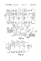
- FIG. 13 is a block diagram of a power control/mobile locator system that can be utilized in this invention.
- FIG. 14 is a block diagram of the demodulator shown in FIG. 13.
- FIG. 15 is a block diagram of an alternate embodiment of the power control/mobile locator system that can be utilized in this invention.
- a hexagonal cellular structure is preferably utilized, with a base station (generally designated 5 in FIG. 1) at the center of each hexagon.
- the base station antenna may be omnidirectional or directional as desired, depending upon the traffic density. The size of the cells can be adjusted as demand for the service grows.
- a central processor, or controller, 7 provides message links via land lines (or other nonbroadcast means, such as optical fiber link or microwave link), generally designated 9 in FIG. 1, to and from each base station (and to and from any other land based services as indicated in FIG. 1).
- the processor thus acts as a telephone exchange and performs all system supervisory functions.
- each base station 5 communicates with the mobile units (generally designated 11) within the cell of that particular base station.
- the available band of frequencies is divided into two portions.
- One portion carries the downstream (base-station-to-mobile) messages, including one dedicated channel per cell reserved for control and supervisory purposes.
- the other portion of the band carries the upstream (mobile-to-base station) messages, including one dedicated channel per cell for call initiation and cell-to-cell handoff.
- These two frequency bands may simply be two separate assignments, not necessarily contiguous or even continuous; or they may be subdivided and interleaved (which may improve the performance of the power control system, which relies on reciprocity between upstream and downstream channels).
- Each channel used to convey information in the system is defined by a small subset of a large spread spectrum signal set.
- the spread spectrum signal set is sufficiently large that a permanent, unique channel assignment can be made to each user in a city, even if there are millions of users.
- Each channel occupies the entire width of the available (upstream or downstream) band, though its spectrum need not be continuous over the band.
- Energy from each user overlaps energy from all other users both in the time and frequency domains.
- Each user recognizes, or responds to, only its own assigned signal subset, separatingg it from the other signals by means of its unique demodulator structure. No attempt is made to synchronize signals from one user to another, and the signals need not be periodic.
- the functions performed by the central processor are as follows:
- Upstream signals are maintained at equal power (measured at the base station) by means of a power control system 14 built into each receiver 16 of each mobile unit 11 (see FIG. 2).
- the mobile unit 11 monitors the downstream control signal from its local base station 5. As shown in FIG. 2, this is accomplished by receiving the incoming signal on antenna 18 and coupling the same through circulator 20 and RF amplifier 22 to downstream control demodulator 24.
- Power control system 14 estimates the mean power and controls the transmitted power so that the product of control signal power and transmitted power is a constant.
- the time-constant of the control circuit is chosen so that at normal vehicular speeds, the power control system compensates for shadow fading but not for Rayleigh fading.
- the output from RF amplifier 22 is also coupled through downstream message demodulator 26 to data sink 28, while data source 30 provides data to upstream message modulator 32, the output of which is coupled through summation circuit 34 and variable gain RF amplifier 36 to circulator 20.
- the power control signal from power controller 14 is coupled to amplifier 36.
- the mobile unit also monitors the received power from all the other nearby base stations, and makes a decision periodically as to which cell it most probably is in. If the current decision is different from its predecessor, the mobile unit initiates a cell transfer request from power controller and mobile locator 14 via the upstream control channel through initiation/handoff/termination controller 38 and upstream control modulator 40.
- message signals are uniquely assigned to each user, and can contain digitized speech or digital data, while control signals are locally unique to one base station but may be re-used at a suitable distance.
- Downstream signals may be transmitted constantly with strength used to control mobile power and in locator decision, and digital information used for call initiation, hand-off and termination, on a time-shared basis.
- Upstream signals may be digital information on a time-shared basis used for call initiation, hand-off and termination, and are transmitted only when these functions are required.
- the spread-spectrum signal set of this invention is a time-frequency coded (TFC) signal set that is essentially a set of frequency-hopped carriers designed to possess certain favorable properties.
- TFC time-frequency coded
- the construction of the signal set is in three stages.
- each signal of the basic signal set is divided into several shorter signals. This subdivision retains the same properties as the basic signal set, but provides a much larger set.
- Each signal thus produced defines a channel; i.e., each signal is uniquely assigned to one user only in the service area.
- the message data is imprinted on each signal by means of differential biphase modulation. Thus the signals act as frequencyhopped carriers for differentially modulated information.
- the basic signal set is a set of sinusoidal, constantenvelope, continuous-phase signals of duration T 1 seconds.
- the frequency of each signal is constant for the duration of each time chip, but is different from time chip to time chip. No frequency is repeated in any one waveform during T 1 seconds.
- the frequency assignments are of the form
- FIG. 3 shows a representative signal in the time-frequency plane.
- the mth permutation operation regenerates the original starting vector S 1 and the sequence of codes is periodic thereafter. Hence there are m distinct sequences.
- the example also serves to illustrate most of the following general properties of the TFC signal sets:
- the one-coincidence property is the design feature which is responsible for the uniformly-small aperiodic cross-correlation property of the TFC signal set.
- the envelope of the normalized cross-correlation function for the one-coincidence sets, V ij ( ⁇ )/E, has been shown to have the following upper and lower bounds-- ##EQU1## This property permits a number of users to transmit independent, unsynchronized signals with minimal mutual interference, provided that all signals are received with equal power.
- the signal waveforms from the undivided signal set have approximately uniform spectra with bandwidth ⁇ mf 1 +1/t 1 .
- the magnitudes of the cross-correlation envelopes set a limit on the number of units which may use the system simultaneously for a given performance criterion (output signal to noise ratio for speech, for example).
- the system does not, however, exhibit a blocking characteristic; if the limit is exceeded, the consequence will simply be a degradation in performance for each unit.
- the system might be substantially overloaded before communication becomes seriously impaired. This is the characteristic known as "graceful degradation under overload conditions.”
- the basic signal set may be split into shorter signals of length n (n ⁇ m) to generate a new set of (m/n)m signals ((x) denotes the largest integer equal to or less than x).
- each signal will be orthogonal to at least (m-1) other signals with synchronization, and to (m/n)-1 signals without synchronization. In either case, the one-coincidence property will still hold for all pairs of divided signals.
- the number of TFC signals generated by the sub-division process is proportional to m 2 (approx.) rather than m in the undivided case. Maximum efficiency occurs if n is an integer power of 2.
- each mobile unit will be assigned one signal from the divided set, and will communicate by imprinting a biphase code onto the assigned waveform.
- each user is both identified and addressed by the same unique signal.
- RADA random access, discrete address
- privacy capabilities as an integral part of the system design.
- p in the hundreds some tens of thousands of unique codes may be generated. For example, suppose this is a system with an available bandwidth of 40 MHz and each user requires a bit rate of 20 kbit/s.
- FIG. 4 shows the number of unique codes, M, versus f 1 t 1 .
- each signal will have n narrow band spectral components distributed quasi-randomly over the band with a frequency spacing (as an average) of B/n where B is the total available bandwidth for the system.
- the signal subset of the third stage assigned to each user is an "alphabet" of 2 n distinct phase-modulated versions of the user's designated frequency sequence. If orthogonal coding is used, each waveform transmitted will contain log 2 n bits of message information.
- the signal received either by or from a mobile unit will arrive at the receiver antenna via a large number of paths.
- the received signal has a coherence bandwidth typically of the order of magnitude of 30 kHz.
- Phase coherence between frequency slots is therefore lost entirely in the channel.
- the received electromagnetic field near the antenna has a coherence distance of about one-half wave-length, so that a moving mobile unit will encounter loss of phase coherence in each frequency slot in a very short time.
- a differentially coherent biphase coding scheme is utilized.
- the time-frequency coded waveforms described above represent only one of a wide variety of similar waveforms possible.
- the demodulator described next can be used with the TFC signal set described above, or with any other time-frequency codes which may arise in the future, provided that the message information is imprinted by the differential bi-phase modulation method just described.
- the signal is delayed in integer multiples of t 1 up to a maximum of (2n-1)t 1 .
- 2n there are 2n separate delayed versions of the signal available in the demodulator;
- Bandpass filters select the appropriate frequency bands from the delayed signals, in the reverse order of the frequency sequence of the desired signal.
- the first frequency is selected at delay points (2n-1) and (n-1)t 1 ; the second at (2n-2)t 1 and (n-2)t 1 ; and so on, with the last frequency selected at nt 1 and zero delay (the filtering process may be performed either before, during or after the delay process).
- Operations (1) and (2) realign the time chips of the two most recent incoming signal waveforms, so that all 2n of them appear at a set of terminals simultaneously;
- Each pair of the delayed signals of the same frequency is multiplied together, then low-pass filtered to remove the double frequency component. This operation compares the phases of corresponding time chips in the two most recent signals. Each low-pass filter output will be positive if the phases are the same (or differing by less than ⁇ /2 radians) and will be negative if the phases are opposing (or differing by greater than ⁇ /2 radians);
- a threshold detector examines the sum of the absolute values of the output of operation (3) and closes a set of n analog gates (sampling switches) when the sum exceeds a specified threshold value. The sampling switches then transfer the n signals to operation (5);
- n sampled signals from operation (4) be the ordered elements of a vector q.
- H be the nth order Hadamard matrix.
- Q is the n vector of output signals. In the absence of noise and fading, Q will have only one nonzero element, corresponding to the transmitted signal. Generally, Q will have no nonzero elements, but the most probable location of the most positive element will still correspond to the transmitted message. Because each element of the vector Q contains energy from all elements of the vector q, the linear combiner operation provides the receiver with a high level of frequency diversity. It is for this reason that the demodulation error performance is nearly as good in a dispersively fading channel as it is in a linear channel.
- the performance of the receiver increases significantly with increasing n (the inventors have determined that n ⁇ 32 is necessary for good performance in the presence of fading); and (6)
- the elements of the vector Q are scanned to identify the most positive element. This element is then declared to correspond to the transmitted message. Operation (6) produces a maximum-likelihood estimate of the transmitted message.
- the estimated message may be expressed in binary form, or any other form compatible with the requirements of the data sink.
- FIGS. 6 and 7 show a number of ways in which the above sequence of operations can be performed.
- tapped delay line 42 (FIG. 6) and 42 1 (FIG. 7) receive the signals and couple the same through band pass filters (generally designated 44 in FIG. 6) or through band pass filters and delays (generally designated 44 1 and 45 1 in FIG. 7) to product detectors 46 (FIG. 6) and 46 1 (FIG. 7).
- the outputs from the detectors are coupled through low pass filters 48 (FIG. 6) and 48 1 (FIG. 7) and through sampling switches 50 (FIG. 6) and 50 1 (FIG. 7) controlled by threshold detectors 52 (FIG. 6) and 52 1 (FIG. 7) to linear combiner and maximum-likelihood decision circuits 54 (FIG. 6) and 54 1 (FIG. 7).
- the basic TFC signal receiver can be broken into two major components.
- the frontend-demodulator unit takes the received radio frequency TFC signal and demodulates the information contained in the 2n time chips of two adjacent waveforms.
- the decoder-decision circuit takes the received information from the frontend-demodulator and decides if the signal received is the desired signal. If the proper signal is received, the decoder-decision circuit decodes the received signal as a member of the code alphabet. The output data corresponding to the code alphabet entry is then delivered as output of the TFC message demodulator.
- This basic receiver structure is used in all receiver applications in the TFC spread spectrum cellular land mobile system, such as message signal and control signal reception.
- Each output of the frontend-demodulator circuit is a member of r.
- Each output is a demodulated differential-phase-shift-keyed sinusoidal pulse from the TFC signal.
- the n sinusoidal pulses that make up the TFC signal are delayed by appropriate amounts so that they are demodulated at the same time.
- the delayed demodulated sinusoidal pulses all arrive at the output at the same time.
- the decoder-decision circuit takes the vector r, the demodulated time coincident TFC signal and compares it to each of the c j . A decision is made as to which of the c j is "most similar" to the received r. The output data corresponding to the chosen code alphabet entry c j is then delivered as output.
- the decoder-decision circuit 58 consists of low-pass filters 60, a threshold device and sampling circuit 62, and a linear combiner and maximum likelihood decision circuit 64.
- the threshold device compares the ##EQU4## to a threshold level. If the ##EQU5## exceeds the threshold level, the signal is sampled and r is input to the linear combiner and ML decision circuit. The ith element of r is the low pass filtered r i (t)+n i (t). The choice of the output is made by maximum likelihood comparison between r and c j . The c j most similar to the r is chosen. The linear combiner and maximum likelihood decision circuit pick the most positive
- This operation could be performed by either dedicated hardware or by a software based microprocessor system.
- the frontend-demodulator circuit can take many forms, such as, for example, as shown in FIGS. 9 through 11, with the embodiment shown in FIGS. 10 and 11 being claimed in the separate application of George R. Cooper, Raymond W. Nettleton and David P. Grybos.
- the basic components are bandpass filters and delay lines arranged in various configurations.
- the center frequencies of the bandpass filters correspond to the frequencies of the n carrier bursts that make up the TFC signal.
- the selection of these center frequencies to correspond to a particular signal in the signal set uniquely determine the coding and address of the receiver.
- Bandpass filters should be of suitable design to facilitate a change in center frequency. This allows one general receiver to be coded to receive any signal in the signal set.
- the delay lines must be able to delay an analog signal by an amount nt 1 , where n is determined by the application of the delay line in the receiver and t 1 is the duration of one chip.
- the delay line bandwidth also depends on the delay line application in a particular receiver configuration. The bandwidth required is typically either at least B, the system bandwidth for the upstream or downstream channel, or the bandwidth of the bandpass filters.
- the delays can be implemented by either pure analog components, sampled analog components, quantizers and digital components or any combination of these techniques.
- the broadband delay frontend-demodulator 72 consists of a tapped delay line 74, a set of bandpass filters 76 and a set of multipliers 78 to demodulate the differential phase modulation.
- the tapped delay line has bandwidth B and total time delay 2T. The spacing between taps correspond to a delay of t 1 .
- the bandpass filters have center frequencies that correspond to the frequencies of the carrier bursts that make up the TFC signal assigned to the receiver.
- the jth multiplier has inputs of y [t-(j-1)t 1 -T] and y [t-(j-1)t 1 ].
- the output r i (t) consists of a dc term that corresponds in part to the information encoded in the jth time chip of the TFC signal.
- the delay may be realized by any of the aforementioned techniques as long as the technology utilized can produce a delay of 2T with bandwidth B and with taps corresponding to delays every t 1 seconds.
- the broadband delay has a time-bandwidth product of 2TB.
- the broadband delay frontend-demodulator configuration may be modified as shown in FIG. 10 by the use of mixers 82 and 84 at the inputs and outputs, respectively, of the delay line 86 and bandpass filters 88 and 90 to suit the center frequency requirements of the delay line and filters.
- Identical BPF's could be used if the local oscillators feeding the mixers are selected to translate the frequency of the ith chip into the BPF filter center frequency.
- the coding of the receiver is then done by adjusting the local oscillators instead of adjusting the BPF center frequencies.
- the narrowband delay frontend-demodulator performs the bandpass operation before the delay lines and is shown in FIG. 11.
- filters 94 receive the input signals and couple the same through delays 96 and 97 to mixers 98. This allows the delay lines to have much smaller bandwidths than the delay line used in the wideband delay frontend-demodulator.
- the delays of T are now required to get y [t-(j-1)t 1 -T] as the second input to the multiplier.
- the narrowband version requires at least 2n-1 narrowband delay lines of various delay times. Only one broadband delay line is required in the broadband delay frontend-demodulator.
- the narrowband delays require time-bandwidth products on the order of 2T/t 1 .
- the basic narrowband delay frontend-demodulator could also be modified by the use of mixers at any point in the circuit.
- the mixers would be used to match the operating frequency requirements of the component devices.
- the narrowband delays could be constructed using any technique capable of the required delay time and bandwidth. This structure is especially suited for the application of charge transfer devices and monolithic integrated circuits.
- the base stations will each be assigned a locally unique TFC signal subset for use as the upstream and downstream control signals (UCS and DCS).
- Each base station transmits its signal periodically and with constant power with a relatively low pulse repetition frequency.
- the purpose of the low p.r.f. is to allow each radiated signal to clear the immediate area before the next base station transmits its signal.
- the DCS of each nearby base station will appear at the input of every receiver at a different time to all the others.
- p.r.f.'s of a few kilohertz, as few as seven distinct DCS frequency sequences allocated in the manner as shown in FIG. 12, will suffice to yield satisfactory operation of the power control/mobile locator system.
- Each receiver contains P demodulators, each designed to receive one of the DCS's.
- the output of each demodulator is a scalar signal proportional in magnitude to the incoming power of its DCS;
- Each demodulator output signal is multiplied by a constant.
- the value of the constant is unity for the (P-1) signals which have not been selected as identifying the local base station; the remaining signal is multiplied by some constant greater than one.
- the purpose of this weighting technique is to introduce some "hysteresis" into the decision process. Hysteresis appears to be desirable in order to discourage vacillation of the locator decision when a mobile unit is near the border of its cell. A constant on the order of 1.5 has been found to give satisfactory results. However, this operation is generally to be regarded as optional;
- the signal identified as coming from the local base station is averaged over H samples, and the averaged signal is used to control the output power of the mobile transmitter. This may be done via a power control loop, a voltage controlled amplifier or attenuator or any other suitable means.
- the law governing the power control operation is that the product of DCS power and transmitted power must be a constant. The constant is determined as a system design parameter and is the same for all mobile units;
- Each weighted demodulator output signal is passed through a threshold detector which passes any signal to its output only if it exceeds a given threshold level.
- the P threshold circuits have the same threshold level.
- the P averaged signals are scanned to determine the most positive signal, and that signal is declared to identify the local base station. This operation amounts to a maximum likelihood estimate of the nearest base station. The decision is passed back to the hysteresis circuit of operation (2) and to the averaging circuit of operation (3).
- FIG. 13 shows a typical block diagram of the power control/mobile locator system.
- the input signals from the IF are coupled through parallel connected demodulators (generally designated 102), weighting circuits (generally designated 104), threshold devices (generally designated 106), integrate and dump circuits (generally designated 108), and switches (generally designated 110) to maximum-likelihood decision circuit 112.
- An output from maximum likelihood decision circuit 112 is coupled to hysteresis generator 114 (which supplies a second input to weighting circuits 104) and to selector 116 which supplies an output to integrate and dump circuit 118.
- Selector 116 also supplies an output through threshold circuit 120 to divide-by-k circuit 122 and divide-by-H circuit 124, which circuits control switches 110 and switch 126, respectively.
- switch 120 When switch 120 is closed, an output is coupled from integrate and dump circuit 118 to sample and hold circuit 128, the output of which is coupled to voltage controlled attenuator 130 through which the upstream signal is coupled to antenna 132.
- the demodulators may be constructed in a similar way to the message demodulator, except that it is necessary only to detect the presence of the signal and its magnitude for the power/mobile locator function. Hence the differential phase operation is not required in general.
- the operations performed by these simplified demodulators are as follows:
- the signal is delayed by integer multiples of t 1 up ro a maximum of (n-1)t 1 . Hence there are n delayed versions of the signal (starting with zero delay) in each demodulator;
- Each delayed signal is bandpass filtered, with center frequency in reverse order of the assigned frequency sequence of the desired DCS.
- the undelayed signal is filtered at f n , and so on, with the (n-1)t 1 delayed signal filtered a f 1 .
- Operations (1) and (2) align the time chips of the signal so that they all appear at the output of the filters simultaneously, and operations (1) and (2) may be reversed in order if desired; and
- the filtered and delayed signals are each squared, lowpass filtered to remove the double frequency component and then summed.
- the output from the summer is therefore proportional to the sum of the squares of the amplitudes of each time-chip component in the selected DCS; i.e., it is an estimate of mean received DCS power.
- the estimate is already averaged over n independent samples because the statistics of each frequency slot are independent in the multipath channel; and the estimate can be improved further by the averaging operation (3) of the power control system.
- FIG. 14 shows a typical block diagram of a power control/mobile locator demodulator. As shown, the input signal is coupled through tapped delay line 134 to parallel circuits each including a bandpass filter 136, squaring circuit 138, and lowpass filter 140, after which the signals are summed at summation circuit 142.
- parallel circuits each including a bandpass filter 136, squaring circuit 138, and lowpass filter 140, after which the signals are summed at summation circuit 142.
- Downstream control signal data will be required for call initiation/termination/handoff operations. This may be differentially phase modulated onto the DCS as described in the spread spectrum signal set description. If this is done, it will be necessary to substitute a message demodulator for the simplified demodulator (just described) corresponding to the local station. This may be done electronically in response to the mobile locator decision, or (if economically feasible) all the demodulators may be of the message type. Probably the most obvious method is to electronically convert the "local" demodulator, when it is identified, from the "simplified" type to the "message" type.
- the power control/vehicle locator signal may be taken from the input to the threshold detector summing circuit of the DCS message demodulator.
- Each base station emits a DCS, on which biphase information is modulated to identify it in a local sense. These emissions are timed such that they cannot coincide in time in the receiver of any mobile unit from nearby base stations;
- TFC Message Demodulator A simple differentially-coherent demodulator as described under "TFC Message Demodulator” is used to extract the binary information in the DCS. (Not all bits in waveform need be used for identification; any remaining bits can be used for other control functions); and
- a "pigeon-holing" operation routes the signal strength information to the appropriate averaging channel for the ML base-station decision, using the binary identification information.
- FIG. 15 One implementation of such a modified power control/mobile locator is shown in FIG. 15. As shown, the functions of this modified power controller/mobile locator are the same as described in connection with the unit as shown in FIG. 12 except that the input from the IF is coupled to a differentially coherent demodulator 144, the binary data output from which is coupled through base station signal sorter 146 to the weighting circuits 104, and the sum of squares output from which is coupled through sample and hold circuit 148 to the base station signal sorter 146 as a signal strength signal.
- the entire operation of the power control/mobile locator system may be implemented digitally.
- a high-speed microprocessor, supported by suitable software, would be ideal for this purpose, and could probably form the nucleus of the entire receiver.
- Priority messages e.g., public safety vehicles
- Priority messages can be accommodated in the system, even in the presence of system overload, without assigning dedicated channels or denying other users access to the system. This can be done either by increasing the power level, on an emergency basis, or by increasing the time-bandwidth product of the signal set; and
- a spread spectrum system may co-exist in the same frequency band as conventional narrowband systems without excessive mutual interference. This suggests the possibility that a spread spectrum system could be phased into operation in a given geographical area without immediately obsoleting existing equipment operating in the same band.
Abstract
An apparatus is disclosed for a cellular mobile communication system utilizing a spread spectrum. A plurality of fixed base stations is connected with a central processor so that calls originating in any cell can terminate in any other cell. The available frequency spectrum is divided such that one-half is used for mobile-to-base station transmission and the other one-half is used for base station-to-mobile unit transmission. A power control/mobile locator system and method is utilized in all mobile units to compensate for changes in signal level and to maintain the average received signal level at the base station constant regardless of the location of the mobile unit within the cell. In addition, each mobile unit has a unique set of time-frequency coded waveforms that are used for both transmission and reception. The waveforms have large time-bandwidth products so that interfering signals are well suppressed, and which provide a large set of signals so that each user can be assigned a unique set of waveforms. Message modulation is accomplished by digitizing the speech and encoding the resulting binary sequences into the set of waveforms available to the user, while detection is accomplished by a demodulation system and method in which the phases of each received waveform are compared with those of the preceding waveform.
Description
The Government has rights in this invention pursuant to Grant No. ENG75-15649 awarded by the National Science Foundation.
This invention relates to communication systems and, more particularly, relates to utilizing a spread spectrum for cellular mobile communication systems.
The land mobile radio service has been in existence for some decades. With few exceptions, the service has been restricted to voice communication via frequency-modulation channels. Current practice is to use a central base-station in a given service area, transmitting sufficient power to cover the entire area with adequate field strength. In some cases, satellite stations transmitting the same message may be used to boost signal strength in hard-to-reach areas (the practice known as "simulcasting").
The current technology has the following limitations; (1) Large transmitted powers are needed to provide adequate coverage in radio "shadow" areas. The resulting field strength pattern is several orders of magnitude more intense than it need be over a large portion of the service area;
(2) Because of the high power required, each radio channel may be used once only over a wide geographical area. This is a highly inefficient use of the available spectrum, and makes necessary increasing use of spectral space as the demand for the service grows; and
(3) The quality of speech is poor because of the phenomenon known as Rayleigh Fading. The subjective effect is of repeated submersion of the required signal in background noise, frequently many times per second if the mobile unit is in motion.
Much recent technical literature has been addressed to the use of a cellular structure as a means of increasing the efficiency of the land-mobile radio service. The proposal is to divide the service area into cells (most often hexagons), each with a base station at its center. The communication link is completed by land line, with radio channels bridging the small gap between each mobile and its nearest base station. If a mobile moves to a new cell, the radio link is switched to the new base station.
The advantages claimed for the cellular/FM LMR system are as follows:
(1) Relatively low transmitted powers are required because each base station need only provide adequate field strength within its own cell;
(2) Each channel may be used more than once, provided this is done in cells which are separated by a sufficient distance. Hence the total set of available channels is divided into subsets, each assigned to a widely distributed group of cells. Adjoining and other nearby cells are all assigned different sets of channels, so that cochannel interference is controlled by the geographic pattern of channel assignments (this strategy results in increased efficiency in the system's use of spectral space); and
(3) The amount of cochannel interference is largely determined by the pattern of channel assignments, and not by cell size. Hence increased demand for service can be accommodated by dividing cells into smaller units.
The limitations and disadvantages of the proposed cellular/FM system are as follows:
(1) The effect of Rayleigh Fading upon signal quality is even worse than in existing systems, because background noise is augmented by cochannel interference;
(2) There is an inverse relationship between the number of channels per MHz which can be assigned to one cell and the resultant speech quality. The trade-off can be improved only by employing space-diversity techniques, which involve combining the signals from more than one antenna. But these techniques add significant complexity to the mobile units, and are very awkward to implement on hand-held mobile units;
(3) As the mobile moves from cell to cell, it is necessary to assign a new channel frequency to it. Thus, the central processor is required to keep track of the location of each mobile unit and of the assignment of each channel, and to issue instructions for changing channels via a dedicated control channel. This adds immensely to the complexity of both central plant and mobile units;
(4) If the mobile moves into a cell in which all assigned channels are occupied, its call will be terminated;
(5) FM channels are unsuitable for the reliable transmission of digital data. Hence the proposed cellular/FM system lacks flexibility with respect to possible new applications; and
(6) Because each user has essentially the same apparatus, eavesdropping is possible and message privacy is lost.
Hence, while mobile radio service is now provided, improvements therein have been needed to enable greater satisfactory use of such service, particularly in providing adequate area coverage and in providing more efficient use of the available frequency spectrum. In addition, while improvements such as cellular communications within a service area have heretofore been proposed, such proposals are not fully satisfactory in solving many of the problems presented and/or create new problems.
This invention provides a novel apparatus and method utilizing a spread spectrum that is particularly useful for cellular mobile communication systems. The apparatus and method of this invention provides reliable, high quality transmission of speech and of digital data to and from mobile radio users, and is particularly useful in areas where the demand for such services is heavy (such as in large cities, for example). The apparatus and method of this invention makes efficient use of the available band of frequencies to enable high geographic user density while eliminating operational disadvantages present or contemplated in utilizing now known or proposed systems, and the apparatus and method is also sufficiently versatile so as to meet a wide variety of now contemplated future requirements and/or applications.
It is therefore an object of this invention to provide a novel communication system utilizing a spread spectrum.
It is another object of this invention to provide a novel communication system for cellular mobile communication systems.
It is still another object of this invention to provide a novel cellular mobile communication system utilizing a spread spectrum.
It is still another object of this invention to provide a novel apparatus and method utilizing a spread spectrum.
It is yet another object of this invention to provide a novel apparatus and method utilizing a spread spectrum in a cellular mobile communication system.
It is still another object of this invention to provide a novel apparatus and method that provides reliable high quality transmission of speech and of digital data to and from mobile radio users.
It is still another object of this invention to provide a novel apparatus and method that makes efficient use of the available band of frequencies to enable high geographic user density.
It is still another object of this invention to provide a novel apparatus and method that eliminates operational disadvantages of now known or proposed systems.
It is still another object of this invention to provide a novel apparatus and method that is versatile.
With these and other objects in view, which will become apparent to one skilled in the art as the description proceeds, this invention resides in the novel construction, combination, and arrangement of parts substantially as hereinafter described, and more particularly defined by the appended claims, it being understood that such changes in the precise embodiment of the herein disclosed invention are meant to be included as come within the scope of the claims.
The accompanying drawings illustrate complete embodiment of the invention according to the best mode so far devised for the practicel application of the principles thereof, and in which:
FIG. 1 is a simplified block diagram of the overall system of this invention;
FIG. 2 is a simplified block diagram of a mobile unit having this invention incorporated therein;
FIG. 3 is a representative time frequency coded waveform;
FIG. 4 is a graph showing the number of unique codes;
FIG. 5 is a graph showing the summary of cross-correlation properties of sets;
FIG. 6 is a received demodulator that may be utilized in this invention;
FIG. 7 is an alternate embodiment of a received demodulator that can be utilized in this invention;
FIG. 8 is a block diagram of a decoder decision circuit that can be utilized in this invention;
FIGS. 9, 10 and 11 are block diagrams of alternate embodiments of the front end of the demodulator that can be used in this invention;
FIG. 12 is a representative cellular layout;
FIG. 13 is a block diagram of a power control/mobile locator system that can be utilized in this invention;
FIG. 14 is a block diagram of the demodulator shown in FIG. 13; and
FIG. 15 is a block diagram of an alternate embodiment of the power control/mobile locator system that can be utilized in this invention.
For this invention, a hexagonal cellular structure is preferably utilized, with a base station (generally designated 5 in FIG. 1) at the center of each hexagon. The base station antenna may be omnidirectional or directional as desired, depending upon the traffic density. The size of the cells can be adjusted as demand for the service grows. A central processor, or controller, 7 provides message links via land lines (or other nonbroadcast means, such as optical fiber link or microwave link), generally designated 9 in FIG. 1, to and from each base station (and to and from any other land based services as indicated in FIG. 1). The processor thus acts as a telephone exchange and performs all system supervisory functions. As also shown in FIG. 1, each base station 5 communicates with the mobile units (generally designated 11) within the cell of that particular base station.
The available band of frequencies is divided into two portions. One portion carries the downstream (base-station-to-mobile) messages, including one dedicated channel per cell reserved for control and supervisory purposes. The other portion of the band carries the upstream (mobile-to-base station) messages, including one dedicated channel per cell for call initiation and cell-to-cell handoff.
These two frequency bands may simply be two separate assignments, not necessarily contiguous or even continuous; or they may be subdivided and interleaved (which may improve the performance of the power control system, which relies on reciprocity between upstream and downstream channels).
Each channel used to convey information in the system is defined by a small subset of a large spread spectrum signal set. The spread spectrum signal set is sufficiently large that a permanent, unique channel assignment can be made to each user in a city, even if there are millions of users. Each channel occupies the entire width of the available (upstream or downstream) band, though its spectrum need not be continuous over the band. Energy from each user overlaps energy from all other users both in the time and frequency domains. Each user recognizes, or responds to, only its own assigned signal subset, separatingg it from the other signals by means of its unique demodulator structure. No attempt is made to synchronize signals from one user to another, and the signals need not be periodic.
The functions performed by the central processor are as follows:
1. Transmit from each base station a locally unique spread-spectrum signal for use as a power control and vehicle locator beacon. This defines the downstream control channel;
2. Initiate downstream calls via the downstream control channel;
3. Respond to upstream initiation requests via the upstream control channel;
4. Keep a record of the location of all active mobile units;
5. Route each call to and from the appropriate base station and/or land-based installation using the system;
6. Respond to cell-change requests, via the upstream control channel, by re-routing the message; and
7. Keep records of calls for logging and billing purposes.
These functions can all be performed by a high speed digital computer equipped with appropriate software and peripheral hardware.
Because of the spectral energy overlap between all the signals, it is essential that all signals from a given cell arrive at the receiver input with equal power. In the downstream case, this follows automatically if all signals are transmitted with equal power since they all pass through the same channel.
Upstream signals are maintained at equal power (measured at the base station) by means of a power control system 14 built into each receiver 16 of each mobile unit 11 (see FIG. 2). The mobile unit 11 monitors the downstream control signal from its local base station 5. As shown in FIG. 2, this is accomplished by receiving the incoming signal on antenna 18 and coupling the same through circulator 20 and RF amplifier 22 to downstream control demodulator 24. Power control system 14 estimates the mean power and controls the transmitted power so that the product of control signal power and transmitted power is a constant. The time-constant of the control circuit is chosen so that at normal vehicular speeds, the power control system compensates for shadow fading but not for Rayleigh fading.
As shown in FIG. 2, the output from RF amplifier 22 is also coupled through downstream message demodulator 26 to data sink 28, while data source 30 provides data to upstream message modulator 32, the output of which is coupled through summation circuit 34 and variable gain RF amplifier 36 to circulator 20. As shown, the power control signal from power controller 14 is coupled to amplifier 36.
The mobile unit also monitors the received power from all the other nearby base stations, and makes a decision periodically as to which cell it most probably is in. If the current decision is different from its predecessor, the mobile unit initiates a cell transfer request from power controller and mobile locator 14 via the upstream control channel through initiation/handoff/termination controller 38 and upstream control modulator 40.
Basing the location decision of field strength measurements is unlikely to yield geographically accurate results, but it does give the strongest possible signal at all times. Hence the vehicle locator system acts like a selectiondiversity device.
Thus, message signals are uniquely assigned to each user, and can contain digitized speech or digital data, while control signals are locally unique to one base station but may be re-used at a suitable distance. Downstream signals may be transmitted constantly with strength used to control mobile power and in locator decision, and digital information used for call initiation, hand-off and termination, on a time-shared basis. Upstream signals may be digital information on a time-shared basis used for call initiation, hand-off and termination, and are transmitted only when these functions are required.
Attention is invited to the following references by Cooper, G. R. and Nettleton, R. W., related to this invention: Cooper, G. R. and Nettletion, R. W., "A spread spectrum technique for high capacity mobile communications", Record of the IEEE Conference of Vehicular Technology, March 1977; Cooper, G. R. and Nettletion, R. W., "Efficient Spectrum Utilization with Wideband Signals," Technical Report TR-EE 77-12, Purdue University, published March 1977; Nettleton, R. W. and Cooper, G. R., "Mutual Interference in Cellular LMR Systems: Narrowband and Broadband Techniques Compared", Record of MIDCON/77, IEEE, November 1977; and Nettleton, R. W. and Cooper, G. R., "Error Performance of a Spread-Spectrum Mobile Communications System in a Rapidly-Fading Environment", Record of the National Telecommunications Conference, IEEE, December 1977.
The spread-spectrum signal set of this invention is a time-frequency coded (TFC) signal set that is essentially a set of frequency-hopped carriers designed to possess certain favorable properties.
The construction of the signal set is in three stages.
First, a small set of long-duration time-frequency coded signals are generated algorithmically. This forms the basic signal set. Second, each signal of the basic signal set is divided into several shorter signals. This subdivision retains the same properties as the basic signal set, but provides a much larger set. Each signal thus produced defines a channel; i.e., each signal is uniquely assigned to one user only in the service area. Third, the message data is imprinted on each signal by means of differential biphase modulation. Thus the signals act as frequencyhopped carriers for differentially modulated information.
The basic signal set is a set of sinusoidal, constantenvelope, continuous-phase signals of duration T1 seconds. Each signal is divided into m time-chips of duration t1 =T1 /m seconds. The frequency of each signal is constant for the duration of each time chip, but is different from time chip to time chip. No frequency is repeated in any one waveform during T1 seconds.
The frequency assignments are of the form
f.sub.i.sup.k =f.sub.o +a.sub.i.sup.k f.sub.1
where fi k is the frequency shift (from some nominal frequency f0) assigned to the ith time chip of the kth signal, and ai k is the ith integer of the kth code in the one-coincidence code set. Hence there are m distinct signal waveforms, each with m time chips, and each with a bandwidth of approximately mf1. (The ai k are permuted from the set of integers (1,2,3, . . . ,m). FIG. 3 shows a representative signal in the time-frequency plane.
The code sequences SK =(a1 K, a2 K, a3 K, . . . , am K), K=1, 2, . . . , m, are all permutations of the integar set (1, 2, 3, . . . , m). Since there are m! such permutations, it is not immediately obvious how one goes about selecting the m "best" permutations from the m! possibilities, or indeed why there should only be m such codes. For a more complete discussion of the theory of construction of the codes, attention is directed to G. R. Cooper and R. D. Yates, "Design of Large Signal Sets with Good Aperiodic Correlation Properties," Purdue University, TR-EE-66-13, September 1966. By contrast, however, the method of actually generating such codes is simple and algorithmic, thus:
1. Select a prime number p. (The selection criteria will become obvious in a later section). Then m=p-1;
2. From the smallest primitive root, b, of p generate the permutation vector II;
π.sub.p ={1, (b), (b.sup.2), . . . , (b.sup.m-1)}
where the operation (Bj) denotes the module-p-reduced, jth power of b; i.e., (x)=x-[x/p]p where [y] denotes the largest integer≦y;
3. Select an arbitrary starting permutation S1 ;
4. Operate on S1 with πp (m-1) times to form the m code sequences. The operation
S.sup.j =π.sub.p S.sup.j-1
means
a.sub.j.sup.1-1 =a.sub.b.sup.j
a.sub.b.sup.j-1 =a.sub.b.sup.j 2
a.sub.b.spsb.m-1.sup.j-1 =a.sub.1.sup.j
The mth permutation operation regenerates the original starting vector S1 and the sequence of codes is periodic thereafter. Hence there are m distinct sequences.
The foregoing is illustrated with a simple example. Let p=7. Then b-3, l and π7 =(1, 3, 2, 6, 4, 5). Select, say, the starting vector
S.sup.1 =(1, 2, 3, 4, 5, 6)
S.sup.2 =(5, 3, 1, 6, 4, 2)
S.sup.3 =(4, 1, 5, 2, 6, 3)
S.sup.4 =(6, 5, 4, 3, 2, 1)
S.sup.5 =(2, 4, 6, 1, 3, 5)
S.sup.6 =(3, 6, 2, 5, 1, 4)
and finally back to S1 =(1, 2, 3, 4, 5, 6) . . . and so on.
The example also serves to illustrate most of the following general properties of the TFC signal sets:
If the codes are synchronized and if f1 t1 =K, where k is any integer, the signals are all mutually orthogonal. That is, no number is repeated in any column of the above code set. Generally the condition f1 t1 =1 would hold for orthogonality, since f1 t1 >1 produces a spectrally inefficient set.
If synchronization is not employed, no two signals have more than one frequency coincidence for any time shift. This is referred to as the one-coincidence property and may be verified by shifting any row in the above code set to the right or left. The one-coincidence property is the design feature which is responsible for the uniformly-small aperiodic cross-correlation property of the TFC signal set. The envelope of the normalized cross-correlation function for the one-coincidence sets, Vij (τ)/E, has been shown to have the following upper and lower bounds-- ##EQU1## This property permits a number of users to transmit independent, unsynchronized signals with minimal mutual interference, provided that all signals are received with equal power. FIG. 5 shows the spread of experimental data in relation to the above bounds, from computer simulations of the system. Note that performance is generally better for the orthogonal (f1 t1 =1) codes, as one would expect. The data was generated from codes in which the starting vector was the permutation operator itself.
The signal waveforms from the undivided signal set have approximately uniform spectra with bandwidth≈mf1 +1/t1.
The magnitudes of the cross-correlation envelopes set a limit on the number of units which may use the system simultaneously for a given performance criterion (output signal to noise ratio for speech, for example). The system does not, however, exhibit a blocking characteristic; if the limit is exceeded, the consequence will simply be a degradation in performance for each unit. Depending on the parameters chosen, the system might be substantially overloaded before communication becomes seriously impaired. This is the characteristic known as "graceful degradation under overload conditions."
The basic signal set may be split into shorter signals of length n (n<m) to generate a new set of (m/n)m signals ((x) denotes the largest integer equal to or less than x). In the new set, if the frequency slots do not overlap, i.e., if f1 t1 =1, each signal will be orthogonal to at least (m-1) other signals with synchronization, and to (m/n)-1 signals without synchronization. In either case, the one-coincidence property will still hold for all pairs of divided signals. The number of TFC signals generated by the sub-division process is proportional to m2 (approx.) rather than m in the undivided case. Maximum efficiency occurs if n is an integer power of 2.
It is the divided TFC signal set that finds application in the mobile radio case. Specifically, it is anticipated that each mobile unit will be assigned one signal from the divided set, and will communicate by imprinting a biphase code onto the assigned waveform. Thus each user is both identified and addressed by the same unique signal. This assures both RADA (random access, discrete address) and privacy capabilities as an integral part of the system design. With p in the hundreds, some tens of thousands of unique codes may be generated. For example, suppose this is a system with an available bandwidth of 40 MHz and each user requires a bit rate of 20 kbit/s. FIG. 4 shows the number of unique codes, M, versus f1 t1.
Note that in the divided signal set case, the signal spectrum from each unit is not expected to be either continuous or uniform. Rather each signal will have n narrow band spectral components distributed quasi-randomly over the band with a frequency spacing (as an average) of B/n where B is the total available bandwidth for the system.
The signal waveforms from the previous stage may each be used as frequency-hopped "carriers" for a biphase (or multiphase) coded message, thus: ##EQU2## where ci k (t)=±1 are constant for a given waveform period and represent the transmitted message; and S represents the power of the signal. The φi are the phase constants needed to give the signal its "continuous-phase" property; i.e., to ensure that the waveform "chips" will "join at the edges." They are not needed (i.e., they are all zero) if fo +f1 t1 =k for k some integer, since this guarantees that each chip will contain an integer number of cycles.
The signal subset of the third stage assigned to each user is an "alphabet" of 2n distinct phase-modulated versions of the user's designated frequency sequence. If orthogonal coding is used, each waveform transmitted will contain log2 n bits of message information.
The signal received either by or from a mobile unit will arrive at the receiver antenna via a large number of paths. Hence the received signal has a coherence bandwidth typically of the order of magnitude of 30 kHz. Phase coherence between frequency slots is therefore lost entirely in the channel. Further, the received electromagnetic field near the antenna has a coherence distance of about one-half wave-length, so that a moving mobile unit will encounter loss of phase coherence in each frequency slot in a very short time.
To overcome this difficulty, a differentially coherent biphase coding scheme is utilized. The phase of each time chip is compared with the phase of the corresponding time chip in the previous waveform to provide the channel information bit contained in that chip. If bi k =±1 is the ith channel bit for the kth transmitted waveform, then ##EQU3##
The channel signal alphabet has n distinct elements, chosen as the rows of the nth order Hadamard matrix H=(hji). If the kth transmitted waveform conveys message element j, then
b.sub.i.sup.k =h.sub.ji.
Since there are n distinct channel message elements, they convey log2 n message bits.
The time-frequency coded waveforms described above represent only one of a wide variety of similar waveforms possible. The demodulator described next can be used with the TFC signal set described above, or with any other time-frequency codes which may arise in the future, provided that the message information is imprinted by the differential bi-phase modulation method just described.
The operations performed on the incoming TFC signal by the message demodulator are as follows:
(1) The signal is delayed in integer multiples of t1 up to a maximum of (2n-1)t1. Thus there are 2n separate delayed versions of the signal available in the demodulator;
(2) Bandpass filters select the appropriate frequency bands from the delayed signals, in the reverse order of the frequency sequence of the desired signal. Hence the first frequency is selected at delay points (2n-1) and (n-1)t1 ; the second at (2n-2)t1 and (n-2)t1 ; and so on, with the last frequency selected at nt1 and zero delay (the filtering process may be performed either before, during or after the delay process). Operations (1) and (2) realign the time chips of the two most recent incoming signal waveforms, so that all 2n of them appear at a set of terminals simultaneously;
(3) Each pair of the delayed signals of the same frequency is multiplied together, then low-pass filtered to remove the double frequency component. This operation compares the phases of corresponding time chips in the two most recent signals. Each low-pass filter output will be positive if the phases are the same (or differing by less than ±π/2 radians) and will be negative if the phases are opposing (or differing by greater than ±π/2 radians);
(4) A threshold detector examines the sum of the absolute values of the output of operation (3) and closes a set of n analog gates (sampling switches) when the sum exceeds a specified threshold value. The sampling switches then transfer the n signals to operation (5);
(5) Let the n sampled signals from operation (4) be the ordered elements of a vector q. Let H be the nth order Hadamard matrix. Then
Q=Hq
describes operation (5), a diagonalizing operation. Q is the n vector of output signals. In the absence of noise and fading, Q will have only one nonzero element, corresponding to the transmitted signal. Generally, Q will have no nonzero elements, but the most probable location of the most positive element will still correspond to the transmitted message. Because each element of the vector Q contains energy from all elements of the vector q, the linear combiner operation provides the receiver with a high level of frequency diversity. It is for this reason that the demodulation error performance is nearly as good in a dispersively fading channel as it is in a linear channel. Also for this reason, the performance of the receiver increases significantly with increasing n (the inventors have determined that n≧32 is necessary for good performance in the presence of fading); and (6) The elements of the vector Q are scanned to identify the most positive element. This element is then declared to correspond to the transmitted message. Operation (6) produces a maximum-likelihood estimate of the transmitted message. The estimated message may be expressed in binary form, or any other form compatible with the requirements of the data sink.
FIGS. 6 and 7 show a number of ways in which the above sequence of operations can be performed. As shown, tapped delay line 42 (FIG. 6) and 421 (FIG. 7) receive the signals and couple the same through band pass filters (generally designated 44 in FIG. 6) or through band pass filters and delays (generally designated 441 and 451 in FIG. 7) to product detectors 46 (FIG. 6) and 461 (FIG. 7). The outputs from the detectors are coupled through low pass filters 48 (FIG. 6) and 481 (FIG. 7) and through sampling switches 50 (FIG. 6) and 501 (FIG. 7) controlled by threshold detectors 52 (FIG. 6) and 521 (FIG. 7) to linear combiner and maximum-likelihood decision circuits 54 (FIG. 6) and 541 (FIG. 7).
The basic TFC signal receiver can be broken into two major components. The frontend-demodulator unit (see FIGS. 9-11) takes the received radio frequency TFC signal and demodulates the information contained in the 2n time chips of two adjacent waveforms. The decoder-decision circuit (see FIG. 8) takes the received information from the frontend-demodulator and decides if the signal received is the desired signal. If the proper signal is received, the decoder-decision circuit decodes the received signal as a member of the code alphabet. The output data corresponding to the code alphabet entry is then delivered as output of the TFC message demodulator.
This basic receiver structure is used in all receiver applications in the TFC spread spectrum cellular land mobile system, such as message signal and control signal reception.
Each output of the frontend-demodulator circuit is a member of r. Each output is a demodulated differential-phase-shift-keyed sinusoidal pulse from the TFC signal. The n sinusoidal pulses that make up the TFC signal are delayed by appropriate amounts so that they are demodulated at the same time. The delayed demodulated sinusoidal pulses all arrive at the output at the same time.
The decoder-decision circuit takes the vector r, the demodulated time coincident TFC signal and compares it to each of the cj. A decision is made as to which of the cj is "most similar" to the received r. The output data corresponding to the chosen code alphabet entry cj is then delivered as output.
Since a decoder-decision circuit is common to all versions of the TFC signal demodulator, regardless of the type of frontend used, it is discussed first.
As shown in FIG. 8, the decoder-decision circuit 58 consists of low-pass filters 60, a threshold device and sampling circuit 62, and a linear combiner and maximum likelihood decision circuit 64.
The threshold device compares the ##EQU4## to a threshold level. If the ##EQU5## exceeds the threshold level, the signal is sampled and r is input to the linear combiner and ML decision circuit. The ith element of r is the low pass filtered ri (t)+ni (t). The choice of the output is made by maximum likelihood comparison between r and cj. The cj most similar to the r is chosen. The linear combiner and maximum likelihood decision circuit pick the most positive
r c.sup.j, j=1, 2, . . . , n.
This operation could be performed by either dedicated hardware or by a software based microprocessor system.
The frontend-demodulator circuit can take many forms, such as, for example, as shown in FIGS. 9 through 11, with the embodiment shown in FIGS. 10 and 11 being claimed in the separate application of George R. Cooper, Raymond W. Nettleton and David P. Grybos. The basic components are bandpass filters and delay lines arranged in various configurations. The center frequencies of the bandpass filters correspond to the frequencies of the n carrier bursts that make up the TFC signal. The selection of these center frequencies to correspond to a particular signal in the signal set uniquely determine the coding and address of the receiver. Bandpass filters should be of suitable design to facilitate a change in center frequency. This allows one general receiver to be coded to receive any signal in the signal set.
The delay lines must be able to delay an analog signal by an amount nt1, where n is determined by the application of the delay line in the receiver and t1 is the duration of one chip. The delay line bandwidth also depends on the delay line application in a particular receiver configuration. The bandwidth required is typically either at least B, the system bandwidth for the upstream or downstream channel, or the bandwidth of the bandpass filters.
The delays can be implemented by either pure analog components, sampled analog components, quantizers and digital components or any combination of these techniques.
The broadband delay frontend-demodulator 72, as shown in FIG. 9, consists of a tapped delay line 74, a set of bandpass filters 76 and a set of multipliers 78 to demodulate the differential phase modulation. The tapped delay line has bandwidth B and total time delay 2T. The spacing between taps correspond to a delay of t1. The bandpass filters have center frequencies that correspond to the frequencies of the carrier bursts that make up the TFC signal assigned to the receiver. The jth multiplier has inputs of y [t-(j-1)t1 -T] and y [t-(j-1)t1 ]. The output ri (t) consists of a dc term that corresponds in part to the information encoded in the jth time chip of the TFC signal.
The delay may be realized by any of the aforementioned techniques as long as the technology utilized can produce a delay of 2T with bandwidth B and with taps corresponding to delays every t1 seconds. The broadband delay has a time-bandwidth product of 2TB.
The broadband delay frontend-demodulator configuration may be modified as shown in FIG. 10 by the use of mixers 82 and 84 at the inputs and outputs, respectively, of the delay line 86 and bandpass filters 88 and 90 to suit the center frequency requirements of the delay line and filters.
Identical BPF's could be used if the local oscillators feeding the mixers are selected to translate the frequency of the ith chip into the BPF filter center frequency. The coding of the receiver is then done by adjusting the local oscillators instead of adjusting the BPF center frequencies.
The narrowband delay frontend-demodulator performs the bandpass operation before the delay lines and is shown in FIG. 11. As shown, filters 94 receive the input signals and couple the same through delays 96 and 97 to mixers 98. This allows the delay lines to have much smaller bandwidths than the delay line used in the wideband delay frontend-demodulator. The delays of T are now required to get y [t-(j-1)t1 -T] as the second input to the multiplier.
This structure allows the use of components that are easier to construct. The narrowband version requires at least 2n-1 narrowband delay lines of various delay times. Only one broadband delay line is required in the broadband delay frontend-demodulator. The narrowband delays require time-bandwidth products on the order of 2T/t1.
The basic narrowband delay frontend-demodulator could also be modified by the use of mixers at any point in the circuit. The mixers would be used to match the operating frequency requirements of the component devices.
The narrowband delays could be constructed using any technique capable of the required delay time and bandwidth. This structure is especially suited for the application of charge transfer devices and monolithic integrated circuits.
It is assumed that the base stations will each be assigned a locally unique TFC signal subset for use as the upstream and downstream control signals (UCS and DCS). Each base station transmits its signal periodically and with constant power with a relatively low pulse repetition frequency. The purpose of the low p.r.f. is to allow each radiated signal to clear the immediate area before the next base station transmits its signal. Hence the DCS of each nearby base station will appear at the input of every receiver at a different time to all the others. With p.r.f.'s of a few kilohertz, as few as seven distinct DCS frequency sequences allocated in the manner as shown in FIG. 12, will suffice to yield satisfactory operation of the power control/mobile locator system.
The operations performed by the power control/mobile locator system are as follows (let P be the number of distince signal subsets assigned to the base stations as DCS's ):
(1) Each receiver contains P demodulators, each designed to receive one of the DCS's. The output of each demodulator is a scalar signal proportional in magnitude to the incoming power of its DCS;
(2) Each demodulator output signal is multiplied by a constant. The value of the constant is unity for the (P-1) signals which have not been selected as identifying the local base station; the remaining signal is multiplied by some constant greater than one. The purpose of this weighting technique is to introduce some "hysteresis" into the decision process. Hysteresis appears to be desirable in order to discourage vacillation of the locator decision when a mobile unit is near the border of its cell. A constant on the order of 1.5 has been found to give satisfactory results. However, this operation is generally to be regarded as optional;
(3) The signal identified as coming from the local base station is averaged over H samples, and the averaged signal is used to control the output power of the mobile transmitter. This may be done via a power control loop, a voltage controlled amplifier or attenuator or any other suitable means. The law governing the power control operation is that the product of DCS power and transmitted power must be a constant. The constant is determined as a system design parameter and is the same for all mobile units;
(4) Each weighted demodulator output signal is passed through a threshold detector which passes any signal to its output only if it exceeds a given threshold level. The P threshold circuits have the same threshold level. These signals are then averaged over K samples, after which the P averaged signals are passed via sampling switches to operation (5); and
(5) The P averaged signals are scanned to determine the most positive signal, and that signal is declared to identify the local base station. This operation amounts to a maximum likelihood estimate of the nearest base station. The decision is passed back to the hysteresis circuit of operation (2) and to the averaging circuit of operation (3).
FIG. 13 shows a typical block diagram of the power control/mobile locator system. As shown, the input signals from the IF are coupled through parallel connected demodulators (generally designated 102), weighting circuits (generally designated 104), threshold devices (generally designated 106), integrate and dump circuits (generally designated 108), and switches (generally designated 110) to maximum-likelihood decision circuit 112. An output from maximum likelihood decision circuit 112 is coupled to hysteresis generator 114 (which supplies a second input to weighting circuits 104) and to selector 116 which supplies an output to integrate and dump circuit 118. Selector 116 also supplies an output through threshold circuit 120 to divide-by-k circuit 122 and divide-by-H circuit 124, which circuits control switches 110 and switch 126, respectively. When switch 120 is closed, an output is coupled from integrate and dump circuit 118 to sample and hold circuit 128, the output of which is coupled to voltage controlled attenuator 130 through which the upstream signal is coupled to antenna 132.
The demodulators may be constructed in a similar way to the message demodulator, except that it is necessary only to detect the presence of the signal and its magnitude for the power/mobile locator function. Hence the differential phase operation is not required in general. The operations performed by these simplified demodulators are as follows:
(1) The signal is delayed by integer multiples of t1 up ro a maximum of (n-1)t1. Hence there are n delayed versions of the signal (starting with zero delay) in each demodulator;
(2) Each delayed signal is bandpass filtered, with center frequency in reverse order of the assigned frequency sequence of the desired DCS. Thus the undelayed signal is filtered at fn, and so on, with the (n-1)t1 delayed signal filtered a f1. Operations (1) and (2) align the time chips of the signal so that they all appear at the output of the filters simultaneously, and operations (1) and (2) may be reversed in order if desired; and
(3) The filtered and delayed signals are each squared, lowpass filtered to remove the double frequency component and then summed. The output from the summer is therefore proportional to the sum of the squares of the amplitudes of each time-chip component in the selected DCS; i.e., it is an estimate of mean received DCS power. The estimate is already averaged over n independent samples because the statistics of each frequency slot are independent in the multipath channel; and the estimate can be improved further by the averaging operation (3) of the power control system.
FIG. 14 shows a typical block diagram of a power control/mobile locator demodulator. As shown, the input signal is coupled through tapped delay line 134 to parallel circuits each including a bandpass filter 136, squaring circuit 138, and lowpass filter 140, after which the signals are summed at summation circuit 142.
Downstream control signal data will be required for call initiation/termination/handoff operations. This may be differentially phase modulated onto the DCS as described in the spread spectrum signal set description. If this is done, it will be necessary to substitute a message demodulator for the simplified demodulator (just described) corresponding to the local station. This may be done electronically in response to the mobile locator decision, or (if economically feasible) all the demodulators may be of the message type. Probably the most obvious method is to electronically convert the "local" demodulator, when it is identified, from the "simplified" type to the "message" type.
The power control/vehicle locator signal may be taken from the input to the threshold detector summing circuit of the DCS message demodulator.
An alternative implementation of the power control/mobile locator system, requiring only one modulator and one DEC waveform, could be implemented if biphase coding is used to identify the base stations instead of a group of different codes. In that case, the following modifications of the system just described are required:
(1) Each base station emits a DCS, on which biphase information is modulated to identify it in a local sense. These emissions are timed such that they cannot coincide in time in the receiver of any mobile unit from nearby base stations;
(2) A simple differentially-coherent demodulator as described under "TFC Message Demodulator" is used to extract the binary information in the DCS. (Not all bits in waveform need be used for identification; any remaining bits can be used for other control functions); and
(3) A "pigeon-holing" operation routes the signal strength information to the appropriate averaging channel for the ML base-station decision, using the binary identification information.
One implementation of such a modified power control/mobile locator is shown in FIG. 15. As shown, the functions of this modified power controller/mobile locator are the same as described in connection with the unit as shown in FIG. 12 except that the input from the IF is coupled to a differentially coherent demodulator 144, the binary data output from which is coupled through base station signal sorter 146 to the weighting circuits 104, and the sum of squares output from which is coupled through sample and hold circuit 148 to the base station signal sorter 146 as a signal strength signal.
If a digitized version of the signal-strength signal is made available, the entire operation of the power control/mobile locator system may be implemented digitally. A high-speed microprocessor, supported by suitable software, would be ideal for this purpose, and could probably form the nucleus of the entire receiver.
Thus, it is felt that this invention provides a new system and method that is unprecedented. The spread-spectrum cellular land mobile system of this invention has numerous inherent advantages over alternative (FM) technology, such as, for example:
(1) The use of large number of frequencies in each waveform results in a form of frequency diversity that significantly reduces the degradation in performance that arises in FM from rapid fading;
(2) Any user can access the system at any time without waiting for a free channel. Thus, there are no blocked calls in the usual sense, as may occur with FM;
(3) Unlike FM, there is no hard limit on the number of active users that can be handled simultaneously by the system. When the number of active users exceeds the design value, the result is a degradation of performance for all users rather than denial of access. This is usually referred to as "graceful degradation";
(4) Since each potential user of the system is assigned a unique signal set, message privacy is achieved as a fringe benefit. This, of course, refers to privacy with respect to the casual listener and does not preclude message interception by a properly equipped third party. (Privacy in FM requires a "scrambler" type installation to be installed);
(5) Because each user retains his unique signal set permanently, there is no channel switching or address changes as the user moves from cell to cell. Hence the particularly objectionable characteristic of FM systems known as "forced termination", which occurs when a mobile crosses a boundary into a cell in which no channel is available, will not occur in this system;
(6) Since all users occupy the same band, all user hardware is identical except for the filter associated with the unique signal set;
(7) Priority messages (e.g., public safety vehicles) can be accommodated in the system, even in the presence of system overload, without assigning dedicated channels or denying other users access to the system. This can be done either by increasing the power level, on an emergency basis, or by increasing the time-bandwidth product of the signal set; and
(8) Under circumstances in which the full capacity of the system is not required, a spread spectrum system may co-exist in the same frequency band as conventional narrowband systems without excessive mutual interference. This suggests the possibility that a spread spectrum system could be phased into operation in a given geographical area without immediately obsoleting existing equipment operating in the same band.
Claims (20)
1. A spread spectrum apparatus for a cellular communication system, said apparatus comprising:
a central controller;
a plurality of spaced base stations operationally connected with said central controller and positioned within preselected cells, each of said base stations being capable of transmitting and receiving different predetermined sets of time-frequency coded waveforms modulated by differential biphase coding at a rate determined by orthogonal sequences of message information with said waveforms extending over a predetermined frequency spectrum common to each of said base stations; and
a plurality of units within said cells with each of said units being operatively responsive only to a predetermined one of said sets of time-frequency coded waveforms to thereby establish selective communication between said base stations and said units.
2. The apparatus of claim 1 wherein said apparatus is used in a mobile communication system, wherein said base stations are fixed stations with a different station centrally located in each of said cells, and wherein said units are located in mobile units capable of moving from cell to cell.
3. The apparatus of claim 2 wherein said base stations and said units both transmit and receive messages included in said sets of time-frequency coded waveforms.
4. The apparatus of claim 3 wherein said predetermined frequency spectrum is divided so that one portion is utilized for mobile unit to base station transmission and the other portion is utilized for base station to mobile unit transmission.
5. The apparatus of claim 2 wherein each of said mobile units includes power control means to maintain the average signal received at a base station approximately constant regardless of the location of said mobile unit within the cell in which said base station is located.
6. The apparatus of claim 1 wherein said sets of time-frequency coded waveforms have large time-bandwidth products such that interferring signals are suppressed.
7. The apparatus of claim 1 wherein said base station and said units include modulation means whereby message information is digitized and the resulting binary sequences encoded into said sets of time-frequency waveforms.
8. The apparatus of claim 7 wherein said base station and said units include demodulator means wherein the phases of each received waveform are compared with those of the preceding waveform.
9. The apparatus of claim 8 wherein said demodulator means includes a tapped delay line, bandpass filters, delays, product detectors, lowpass filters, samplers controlled by a threshold detector, and a linear combining and maximum-likelihood decision circuit.
10. A spread spectrum apparatus for a cellular communication system, said apparatus comprising:
a central controller;
a plurality of fixed base stations each of which is centrally located in a different geographical cell, each of said base stations being operatively connected with said central controller and capable of transmitting and receiving different predetermined sets of time-frequency coded waveforms modulated by differential biphase coding at a rate determined by orthogonal sequences of message information with said waveforms extending over a predetermined frequency spectrum common to each of said base stations; and
a plurality of mobile units each of which is capable of movement between said cells, each of which is capable of transmitting and receiving only one predetermined set of said sets of time-frequency coded waveforms, and each of which includes power control means whereby transmitted signals are received at the base station with the cell of the transmitting mobile unit at an approximately constant average level.
11. The apparatus of claim 10 wherein said sets of time-frequency coded waveforms have uniformly small cross correlation functions for any relative time shift.
12. The apparatus of claim 11 wherein said sets of time-frequency coded waveforms are composed of time-frequency coded signals having one-coincidence properties.
13. The apparatus of claim 12 wherein said sets of time-frequency coded waveforms have a duration of T=mt1 where t1 is the chip duration and m is one less than a prime number, with a predetermined constant frequency being transmitted during each chip that differs from the preselected nominal carrier frequency by an integral multiple of a predetermined basic frequency shift.
14. The apparatus of claim 10 wherein each of said mobile units includes means connected with said power control means to initiate a signal requesting base station transfer when a mobile unit is sensed outside the cell containing the base station then in communication with said mobile unit.
15. A signal demodulator for a spread spectrum communication system, said demodulator comprising:
first means for receiving a spread spectrum input signal that includes waveforms having time chips with differential biphase coding at a rate determined by orthogonal sequences of message information and demodulating the information contained in the time chips of two adjacent waveforms thereof; and
second means connected with said first means and responsive to an output therefrom deciding if the input signal is the desired signal and if so decoding the same.
16. The demodulator of claim 15 wherein said first means includes a tapped delay line, a set of bandpass filters, and a set of multipliers to demodulate the differential phase modulation.
17. The demodulator of claim 16 wherein said bandpass filters have center frequencies that correspond to the requirements of the received desired signal.
18. The demodulator of claim 15 wherein said second means includes a set of low pass filters, a threshold circuit controlling a set of sampling switches, and a linear combiner and maximum likelihood decision circuit.
19. A power control and mobile locator unit for a spread spectrum communications system, said power control and mobile locator unit comprising:
a plurality of demodulators each of which receives different predetermined control signals each of which produces an output that is a scalar signal proportional in magnitude to the power of the received incoming signal;
a plurality of weighting circuits each of which receive a different one of said outputs from said plurality of demodulators and multiplies the same by a predetermined constant to thereby introduce hysteresis;
a plurality of threshold circuits each of which receives a different one of said outputs from said weighting circuits;
a plurality of integrate and dump circuits each of which receives a different one of said outputs from said plurality of threshold circuits;
a plurality of sampling switches each of which is connected with a different one of said integrate and dump circuits; and
a maximum likelihood decision circuit for receiving the outputs from said integrate and dump circuits and identifying the nearest base station therefrom.
20. A method for forming a signal set for a spread spectrum communication system, said method comprising:
generating algorithmically a small set of long-duration time-frequency coded signals to form a basic signal set;
dividing the formed basic signal set into a plurality of shorter signals retaining the same properties of the basic signal set to define a channel; and
modulating message data on each channel by differential biphase modulation at a rate determined by orthogonal sequences of message information.
Priority Applications (1)
| Application Number | Priority Date | Filing Date | Title |
|---|---|---|---|
| US05/886,099 US4222115A (en) | 1978-03-13 | 1978-03-13 | Spread spectrum apparatus for cellular mobile communication systems |
Applications Claiming Priority (1)
| Application Number | Priority Date | Filing Date | Title |
|---|---|---|---|
| US05/886,099 US4222115A (en) | 1978-03-13 | 1978-03-13 | Spread spectrum apparatus for cellular mobile communication systems |
Publications (1)
| Publication Number | Publication Date |
|---|---|
| US4222115A true US4222115A (en) | 1980-09-09 |
Family
ID=25388378
Family Applications (1)
| Application Number | Title | Priority Date | Filing Date |
|---|---|---|---|
| US05/886,099 Expired - Lifetime US4222115A (en) | 1978-03-13 | 1978-03-13 | Spread spectrum apparatus for cellular mobile communication systems |
Country Status (1)
| Country | Link |
|---|---|
| US (1) | US4222115A (en) |
Cited By (198)
| Publication number | Priority date | Publication date | Assignee | Title |
|---|---|---|---|---|
| EP0064686A1 (en) * | 1981-05-07 | 1982-11-17 | Alcatel N.V. | Message transmission system |
| WO1983003505A1 (en) * | 1982-03-29 | 1983-10-13 | Western Electric Co | Frequency-hopped single sideband mobile radio system |
| US4411017A (en) * | 1980-03-14 | 1983-10-18 | Harris Corporation | Secure mobile telephone system |
| US4514852A (en) * | 1981-09-15 | 1985-04-30 | Siemens Aktiengesellschaft | Process for protected transmission of digital signals |
| US4550414A (en) * | 1983-04-12 | 1985-10-29 | Charles Stark Draper Laboratory, Inc. | Spread spectrum adaptive code tracker |
| EP0188836A2 (en) * | 1984-12-22 | 1986-07-30 | Philips Patentverwaltung GmbH | Method and device for information transmission in a digital radio transmission system |
| FR2577090A1 (en) * | 1985-02-04 | 1986-08-08 | Mitel Telecom Ltd | RADIOCOMMUNICATION SYSTEM |
| US4639914A (en) * | 1984-12-06 | 1987-01-27 | At&T Bell Laboratories | Wireless PBX/LAN system with optimum combining |
| US4654859A (en) * | 1986-04-09 | 1987-03-31 | Racal Data Communications Inc. | Frequency synthesizer for frequency hopping communication system |
| US4704733A (en) * | 1985-12-16 | 1987-11-03 | Minoru Kawano | Cell enhancer for cellular radio telephone system having diversity function |
| US4850036A (en) * | 1987-08-21 | 1989-07-18 | American Telephone And Telegraph Company | Radio communication system using synchronous frequency hopping transmissions |
| US4872205A (en) * | 1987-08-21 | 1989-10-03 | American Telephone And Telegraph Company | Radio communication system having autonomously selected transmission frequencies |
| US4901307A (en) * | 1986-10-17 | 1990-02-13 | Qualcomm, Inc. | Spread spectrum multiple access communication system using satellite or terrestrial repeaters |
| FR2640448A1 (en) * | 1980-10-13 | 1990-06-15 | Trt Telecom Radio Electr | NETWORK-BASED INFORMATION TRANSMISSION SYSTEM USING FREQUENCY HOPPING A SET OF CHANNELS |
| WO1990011658A1 (en) * | 1989-03-23 | 1990-10-04 | Echelon Systems Corporation | A transceiver employing direct sequence spread spectrum techniques |
| US4972430A (en) * | 1989-03-06 | 1990-11-20 | Raytheon Company | Spread spectrum signal detector |
| US4977577A (en) * | 1988-11-02 | 1990-12-11 | Axonn Corporation | Wireless alarm system |
| US4984247A (en) * | 1988-09-29 | 1991-01-08 | Ascom Zelcom Ag | Digital radio transmission system for a cellular network, using the spread spectrum method |
| US4985899A (en) * | 1989-10-05 | 1991-01-15 | The Boeing Company | Intercept detector for spread-spectrum signals |
| EP0422467A2 (en) * | 1989-10-10 | 1991-04-17 | Hughes Aircraft Company | HF high data rate modem |
| WO1991007020A1 (en) * | 1989-11-07 | 1991-05-16 | Qualcomm Incorporated | Soft handoff in a cdma cellular telephone system |
| US5056109A (en) * | 1989-11-07 | 1991-10-08 | Qualcomm, Inc. | Method and apparatus for controlling transmission power in a cdma cellular mobile telephone system |
| US5063572A (en) * | 1990-06-04 | 1991-11-05 | Unisys Corporation | Channelized delay and mix chip rate detector |
| US5067136A (en) * | 1988-11-02 | 1991-11-19 | Axonn Corporation | Wireless alarm system |
| US5073900A (en) * | 1990-03-19 | 1991-12-17 | Mallinckrodt Albert J | Integrated cellular communications system |
| US5095493A (en) * | 1988-11-02 | 1992-03-10 | Axonn Corporation | Wireless alarm system |
| WO1992006543A1 (en) * | 1990-09-27 | 1992-04-16 | Motorola, Inc. | Communication transfer in a radiotelephone system |
| US5109390A (en) * | 1989-11-07 | 1992-04-28 | Qualcomm Incorporated | Diversity receiver in a cdma cellular telephone system |
| WO1992009156A1 (en) * | 1990-11-16 | 1992-05-29 | Scs Mobilecom, Inc. | Adaptive power control for a spread spectrum transmitter |
| WO1992010891A1 (en) * | 1990-12-05 | 1992-06-25 | Scs Mobilecom, Inc. | Spread spectrum cdma communications system |
| WO1992013284A1 (en) * | 1991-01-28 | 1992-08-06 | Han Lee Song | Vehicle locating and navigating system |
| US5142534A (en) * | 1990-10-17 | 1992-08-25 | O'neill Communications, Inc. | Wireless integrated voice-data communication system |
| FR2673345A1 (en) * | 1991-02-22 | 1992-08-28 | Motorola Inc | METHOD AND DEVICE FOR IDENTIFYING THE NEAREST BASE SITE IN A CELLULAR TELECOMMUNICATION SYSTEM |
| EP0507386A1 (en) * | 1991-04-02 | 1992-10-07 | Philips Communication D'entreprise | Information transmission system with at least one base station and one satellite station |
| WO1992017989A1 (en) * | 1991-04-08 | 1992-10-15 | Omnipoint Corporation | Three-cell wireless communication system |
| US5157686A (en) * | 1990-05-24 | 1992-10-20 | Cylink Corporation | Method and apparatus for the modulation of spread spectrum radio signals |
| US5161168A (en) * | 1991-05-15 | 1992-11-03 | Scs Mobilecom, Inc. | Spread spectrum CDMA communications system microwave overlay |
| US5166951A (en) * | 1991-05-15 | 1992-11-24 | Scs Mobilecom, Inc. | High capacity spread spectrum channel |
| US5166952A (en) * | 1990-05-24 | 1992-11-24 | Cylink Corporation | Method and apparatus for the reception and demodulation of spread spectrum radio signals |
| WO1992021196A1 (en) * | 1991-05-17 | 1992-11-26 | Qualcomm Incorporated | Method and apparatus for controlling transmission power in a cdma cellular mobile telephone system |
| WO1992021195A1 (en) * | 1991-05-13 | 1992-11-26 | Omnipoint Corporation | Dual mode transmitter and receiver |
| US5185762A (en) * | 1991-05-15 | 1993-02-09 | Scs Mobilecom, Inc. | Spread spectrum microwave overlay with notch filter |
| US5189683A (en) * | 1989-03-23 | 1993-02-23 | Echelon Corporation | Transceiver providing selectable frequencies and spreading sequences |
| US5203010A (en) * | 1990-11-13 | 1993-04-13 | Motorola, Inc. | Radio telephone system incorporating multiple time periods for communication transfer |
| WO1993009626A1 (en) * | 1991-10-28 | 1993-05-13 | Motorola, Inc. | A method for compensating for capacity overload in a spread spectrum communication system |
| US5218618A (en) * | 1990-11-07 | 1993-06-08 | Hughes Aircraft Company | Cellular telephone service using spread spectrum transmission |
| US5224121A (en) * | 1992-06-04 | 1993-06-29 | Motorola, Inc. | Rolling synthesizer method for baseband slow frequency hopping |
| US5224120A (en) * | 1990-12-05 | 1993-06-29 | Interdigital Technology Corporation | Dynamic capacity allocation CDMA spread spectrum communications |
| US5228056A (en) * | 1990-12-14 | 1993-07-13 | Interdigital Technology Corporation | Synchronous spread-spectrum communications system and method |
| US5228053A (en) * | 1991-05-15 | 1993-07-13 | Interdigital Technology Corporation | Spread spectrum cellular overlay CDMA communications system |
| US5235615A (en) * | 1991-05-22 | 1993-08-10 | Cylink Corporation | Spread spectrum method |
| US5253268A (en) * | 1990-05-24 | 1993-10-12 | Cylink Corporation | Method and apparatus for the correlation of sample bits of spread spectrum radio signals |
| US5257283A (en) * | 1989-11-07 | 1993-10-26 | Qualcomm Incorporated | Spread spectrum transmitter power control method and system |
| US5260968A (en) * | 1992-06-23 | 1993-11-09 | The Regents Of The University Of California | Method and apparatus for multiplexing communications signals through blind adaptive spatial filtering |
| US5263045A (en) * | 1990-12-05 | 1993-11-16 | Interdigital Technology Corporation | Spread spectrum conference call system and method |
| US5267261A (en) * | 1992-03-05 | 1993-11-30 | Qualcomm Incorporated | Mobile station assisted soft handoff in a CDMA cellular communications system |
| US5267262A (en) * | 1989-11-07 | 1993-11-30 | Qualcomm Incorporated | Transmitter power control system |
| US5274665A (en) * | 1990-12-14 | 1993-12-28 | Interdigital Technology Corporation | Polyopoly overlapping spread spectrum communication system and method |
| US5276704A (en) * | 1990-07-23 | 1994-01-04 | Omnipoint Data Company, Inc. | SAWC phase detection method and apparatus |
| FR2693330A1 (en) * | 1992-07-01 | 1994-01-07 | Motorola Inc | Method for performing an assisted transfer for a mobile station in a telecommunications system. |
| US5283806A (en) * | 1991-07-18 | 1994-02-01 | Alcatel N.V. | Method of sequencing signal processing in the communication mode of a digital cellular radio system |
| US5285469A (en) * | 1991-06-03 | 1994-02-08 | Omnipoint Data Corporation | Spread spectrum wireless telephone system |
| US5299226A (en) * | 1990-11-16 | 1994-03-29 | Interdigital Technology Corporation | Adaptive power control for a spread spectrum communications system and method |
| US5305468A (en) * | 1992-03-18 | 1994-04-19 | Motorola, Inc. | Power control method for use in a communication system |
| US5313489A (en) * | 1993-06-25 | 1994-05-17 | Motorola, Inc. | Signal processing in communication systems |
| US5335246A (en) * | 1992-08-20 | 1994-08-02 | Nexus Telecommunication Systems, Ltd. | Pager with reverse paging facility |
| US5339331A (en) * | 1993-09-09 | 1994-08-16 | Lockheed Corporation | Frequency hopping spread spectrum receiver |
| US5345467A (en) * | 1991-07-10 | 1994-09-06 | Interdigital Technology Corp. | CDMA cellular hand-off apparatus and method |
| US5355389A (en) * | 1993-01-13 | 1994-10-11 | Omnipoint Corporation | Reciprocal mode saw correlator method and apparatus |
| US5357541A (en) * | 1989-03-23 | 1994-10-18 | Echelon Corporation | Transceiver providing selectable frequencies and spreading sequences |
| EP0620658A1 (en) * | 1992-11-04 | 1994-10-19 | Ntt Mobile Communications Network Inc. | Code division multiplex access mobile communication system |
| US5367533A (en) * | 1990-12-05 | 1994-11-22 | Interdigital Technology Corporation | Dynamic capacity allocation CDMA spread spectrum communications |
| US5379047A (en) * | 1992-08-20 | 1995-01-03 | Nexus Telecommunication Systems, Inc. | Remote position determination system |
| US5384826A (en) * | 1990-10-01 | 1995-01-24 | At&T Bell Laboratories | Distributed packetized switching cellular radio telephone communication system with handoff |
| US5396515A (en) * | 1989-08-07 | 1995-03-07 | Omnipoint Corporation | Asymmetric spread spectrum correlator |
| US5410568A (en) * | 1992-01-13 | 1995-04-25 | Interdigital Technology Corporation | CDMA/TDMA spread-spectrum communications system and method |
| EP0652648A1 (en) * | 1993-11-05 | 1995-05-10 | Matsushita Electric Industrial Co., Ltd. | Transmitting and receiving apparatus |
| US5430760A (en) * | 1992-04-10 | 1995-07-04 | Ericsson Ge Mobile Communications Inc. | Random access in mobile radio telephone systems |
| US5430759A (en) * | 1992-08-20 | 1995-07-04 | Nexus 1994 Limited | Low-power frequency-hopped spread spectrum reverse paging system |
| US5437054A (en) * | 1993-02-05 | 1995-07-25 | The Research Foundation Of State University Of New York | Method and apparatus of assigning and sharing channels in a cellular communication system |
| EP0668665A1 (en) * | 1994-02-16 | 1995-08-23 | Matsushita Electric Industrial Co., Ltd. | Transmission power control for a DS/FH-CDMA system |
| US5455822A (en) * | 1990-10-23 | 1995-10-03 | Omnipoint Corporation | Method and apparatus for establishing spread spectrum communication |
| US5465269A (en) * | 1994-02-02 | 1995-11-07 | Motorola, Inc. | Method and apparatus for encoding and decoding a supplementary signal |
| US5485486A (en) * | 1989-11-07 | 1996-01-16 | Qualcomm Incorporated | Method and apparatus for controlling transmission power in a CDMA cellular mobile telephone system |
| US5499265A (en) * | 1989-08-07 | 1996-03-12 | Omnipoint Data Company, Incorporated | Spread spectrum correlator |
| WO1996013909A1 (en) * | 1994-10-31 | 1996-05-09 | Nokia Mobile Phones Ltd. | Method and arrangement for separating signals operating in the same channel |
| US5535238A (en) * | 1990-11-16 | 1996-07-09 | Interdigital Technology Corporation | Spread spectrum adaptive power control communications system and method |
| US5574750A (en) * | 1993-09-14 | 1996-11-12 | Pacific Communication Sciences, Inc. | Methods and apparatus for detecting a cellular digital packet data (CDPD) carrier |
| US5574747A (en) * | 1995-01-04 | 1996-11-12 | Interdigital Technology Corporation | Spread spectrum adaptive power control system and method |
| US5579338A (en) * | 1992-06-29 | 1996-11-26 | Mitsubishi Denki Kabushiki Kaisha | Spread spectrum receiver using partial correlations |
| WO1996039749A1 (en) * | 1995-06-05 | 1996-12-12 | Omnipoint Corporation | Timing adjustment control for efficient time division duplex communication |
| US5610906A (en) * | 1994-06-29 | 1997-03-11 | Interdigital Technology Corporation | Spread-spectrum changeable base station |
| US5610940A (en) * | 1994-09-09 | 1997-03-11 | Omnipoint Corporation | Method and apparatus for noncoherent reception and correlation of a continous phase modulated signal |
| US5625876A (en) * | 1993-10-28 | 1997-04-29 | Qualcomm Incorporated | Method and apparatus for performing handoff between sectors of a common base station |
| US5627856A (en) * | 1994-09-09 | 1997-05-06 | Omnipoint Corporation | Method and apparatus for receiving and despreading a continuous phase-modulated spread spectrum signal using self-synchronizing correlators |
| US5629956A (en) * | 1994-09-09 | 1997-05-13 | Omnipoint Corporation | Method and apparatus for reception and noncoherent serial correlation of a continuous phase modulated signal |
| US5631921A (en) * | 1990-11-16 | 1997-05-20 | Interdigital Technology Corp. | Adaptive power control for a spread spectrum communications system and method |
| US5648955A (en) * | 1993-11-01 | 1997-07-15 | Omnipoint Corporation | Method for power control in a TDMA spread spectrum communication system |
| US5648982A (en) * | 1994-09-09 | 1997-07-15 | Omnipoint Corporation | Spread spectrum transmitter |
| US5657358A (en) * | 1985-03-20 | 1997-08-12 | Interdigital Technology Corporation | Subscriber RF telephone system for providing multiple speech and/or data signals simultaneously over either a single or plurality of RF channels |
| US5657343A (en) * | 1993-02-17 | 1997-08-12 | Interdigital Technology Corporation | Frequency hopping code division multiple access system and method |
| US5659574A (en) * | 1994-09-09 | 1997-08-19 | Omnipoint Corporation | Multi-bit correlation of continuous phase modulated signals |
| US5677778A (en) * | 1993-05-28 | 1997-10-14 | Interdigital Technology Corporation | Optical interconnect for high speed processors |
| US5680414A (en) * | 1994-09-09 | 1997-10-21 | Omnipoint Corporation | Synchronization apparatus and method for spread spectrum receiver |
| US5682256A (en) * | 1988-11-11 | 1997-10-28 | British Telecommunications Public Limited Company | Communications system |
| US5689502A (en) * | 1995-06-05 | 1997-11-18 | Omnipoint Corporation | Efficient frequency division duplex communication system with interleaved format and timing adjustment control |
| US5692007A (en) * | 1994-09-09 | 1997-11-25 | Omnipoint Corporation | Method and apparatus for differential phase encoding and decoding in spread-spectrum communication systems with continuous-phase modulation |
| US5694414A (en) * | 1991-05-13 | 1997-12-02 | Omnipoint Corporation | Multi-band, multi-mode spread-spectrum communication system |
| US5715236A (en) * | 1990-06-25 | 1998-02-03 | Qualcomm Incorporated | System and method for generating signal waveforms in a CDMA cellular telephone system |
| US5722043A (en) * | 1993-02-05 | 1998-02-24 | The Research Foundation Of State University Of New York | Method and apparatus of assigning and sharing channels in a cellular communication system |
| US5724383A (en) * | 1993-11-01 | 1998-03-03 | Omnipoint Corporation | Method for generating and encoding signals for spread spectrum communication |
| US5742638A (en) * | 1991-12-16 | 1998-04-21 | Omnipoint Corporation | Spread-spectrum data publishing system |
| US5745484A (en) * | 1995-06-05 | 1998-04-28 | Omnipoint Corporation | Efficient communication system using time division multiplexing and timing adjustment control |
| US5754585A (en) * | 1994-09-09 | 1998-05-19 | Omnipoint Corporation | Method and apparatus for serial noncoherent correlation of a spread spectrum signal |
| US5754584A (en) * | 1994-09-09 | 1998-05-19 | Omnipoint Corporation | Non-coherent spread-spectrum continuous-phase modulation communication system |
| US5757847A (en) * | 1994-09-09 | 1998-05-26 | Omnipoint Corporation | Method and apparatus for decoding a phase encoded signal |
| US5787076A (en) * | 1993-11-01 | 1998-07-28 | Omnipoint Corporation | Multi-mode TDMA spread spectrum communication system |
| US5790587A (en) * | 1991-05-13 | 1998-08-04 | Omnipoint Corporation | Multi-band, multi-mode spread-spectrum communication system |
| US5796772A (en) * | 1991-05-13 | 1998-08-18 | Omnipoint Corporation | Multi-band, multi-mode spread-spectrum communication system |
| US5802046A (en) * | 1995-06-05 | 1998-09-01 | Omnipoint Corporation | Efficient time division duplex communication system with interleaved format and timing adjustment control |
| US5815525A (en) * | 1991-05-13 | 1998-09-29 | Omnipoint Corporation | Multi-band, multi-mode spread-spectrum communication system |
| US5822318A (en) * | 1994-07-29 | 1998-10-13 | Qualcomm Incorporated | Method and apparatus for controlling power in a variable rate communication system |
| US5832028A (en) * | 1994-09-09 | 1998-11-03 | Omnipoint Corporation | Method and apparatus for coherent serial correlation of a spread spectrum signal |
| US5852604A (en) * | 1993-09-30 | 1998-12-22 | Interdigital Technology Corporation | Modularly clustered radiotelephone system |
| US5854808A (en) * | 1993-09-14 | 1998-12-29 | Pacific Communication Sciences | Methods and apparatus for detecting the presence of a prescribed signal in a channel of a communications system |
| USRE36017E (en) * | 1988-02-29 | 1998-12-29 | Telefonaktiebolaget Lm Ericsson | Cellular digital mobile radio system and method of transmitting information in a digital cellular mobile radio system |
| US5856998A (en) * | 1994-09-09 | 1999-01-05 | Omnipoint Corporation | Method and apparatus for correlating a continuous phase modulated spread spectrum signal |
| US5859842A (en) * | 1994-11-03 | 1999-01-12 | Omnipoint Corporation | Antenna diversity techniques |
| US5864760A (en) * | 1993-10-28 | 1999-01-26 | Qualcomm Incorporated | Method and apparatus for reducing the average transmit power from a sectorized base station |
| US5864578A (en) * | 1996-04-29 | 1999-01-26 | Golden Bridge Technology, Inc. | Matched filter-based handoff method and apparatus |
| USRE36078E (en) * | 1988-06-14 | 1999-02-02 | Telefonaktiebolaget Lm Ericsson | Handover method for mobile radio system |
| US5881100A (en) * | 1994-09-09 | 1999-03-09 | Omnipoint Corporation | Method and apparatus for coherent correlation of a spread spectrum signal |
| US5887020A (en) * | 1991-05-13 | 1999-03-23 | Omnipoint Corporation | Multi-band, multi-mode spread-spectrum communication system |
| US5893035A (en) * | 1996-09-16 | 1999-04-06 | Qualcomm Incorporated | Centralized forward link power control |
| US5918169A (en) * | 1996-09-25 | 1999-06-29 | Ericsson, Inc. | Homodyne cellular base station |
| US5926500A (en) * | 1996-05-28 | 1999-07-20 | Qualcomm Incorporated | Reduced peak-to-average transmit power high data rate CDMA wireless communication system |
| US5930230A (en) * | 1996-05-28 | 1999-07-27 | Qualcomm Incorporated | High data rate CDMA wireless communication system |
| US5933787A (en) * | 1995-03-13 | 1999-08-03 | Qualcomm Incorporated | Method and apparatus for performing handoff between sectors of a common base station |
| US5940753A (en) * | 1990-03-19 | 1999-08-17 | Celsat America, Inc. | Controller for cellular communications system |
| US5953370A (en) * | 1994-09-09 | 1999-09-14 | Omnipoint Corporation | Apparatus for receiving and correlating a spread spectrum signal |
| US5960361A (en) * | 1996-10-22 | 1999-09-28 | Qualcomm Incorporated | Method and apparatus for performing a fast downward move in a cellular telephone forward link power control system |
| US5959980A (en) * | 1995-06-05 | 1999-09-28 | Omnipoint Corporation | Timing adjustment control for efficient time division duplex communication |
| US5963586A (en) * | 1994-09-09 | 1999-10-05 | Omnipoint Corporation | Method and apparatus for parallel noncoherent correlation of a spread spectrum signal |
| US5974039A (en) * | 1990-12-05 | 1999-10-26 | Interdigital Technology Corporation | CDMA communications and geolocation system and method |
| US5987058A (en) * | 1988-11-02 | 1999-11-16 | Axonn Corporation | Wireless alarm system |
| US5991284A (en) * | 1997-02-13 | 1999-11-23 | Qualcomm Inc. | Subchannel control loop |
| US6002933A (en) * | 1997-04-29 | 1999-12-14 | Qualcomm Incorporated | Inter-system soft handoff |
| US6011789A (en) * | 1990-12-05 | 2000-01-04 | Interdigital Technology Corporation | Broadband CDMA overlay system and method |
| US6021122A (en) * | 1996-06-07 | 2000-02-01 | Qualcomm Incorporated | Method and apparatus for performing idle handoff in a multiple access communication system |
| US6035209A (en) * | 1995-03-31 | 2000-03-07 | Qualcomm Incorporated | Method and apparatus for performing fast power control in a mobile communication system |
| US6041046A (en) * | 1995-07-14 | 2000-03-21 | Omnipoint Corporation | Cyclic time hopping in time division multiple access communication system |
| US6075974A (en) * | 1996-11-20 | 2000-06-13 | Qualcomm Inc. | Method and apparatus for adjusting thresholds and measurements of received signals by anticipating power control commands yet to be executed |
| US6094575A (en) * | 1993-11-01 | 2000-07-25 | Omnipoint Corporation | Communication system and method |
| US6097972A (en) * | 1997-08-29 | 2000-08-01 | Qualcomm Incorporated | Method and apparatus for processing power control signals in CDMA mobile telephone system |
| US6137840A (en) * | 1995-03-31 | 2000-10-24 | Qualcomm Incorporated | Method and apparatus for performing fast power control in a mobile communication system |
| US6141373A (en) * | 1996-11-15 | 2000-10-31 | Omnipoint Corporation | Preamble code structure and detection method and apparatus |
| US6157668A (en) * | 1993-10-28 | 2000-12-05 | Qualcomm Inc. | Method and apparatus for reducing the average transmit power of a base station |
| US6215777B1 (en) | 1997-09-15 | 2001-04-10 | Qualcomm Inc. | Method and apparatus for transmitting and receiving data multiplexed onto multiple code channels, frequencies and base stations |
| US6282228B1 (en) | 1997-03-20 | 2001-08-28 | Xircom, Inc. | Spread spectrum codes for use in communication |
| US20010030948A1 (en) * | 1997-09-08 | 2001-10-18 | Tiedemann Edward G. | Method and system for changing forward traffic channel power allocation during soft handoff |
| US20010033562A1 (en) * | 1990-12-05 | 2001-10-25 | Interdigital Technology Corporation, Delaware Corporation | Broadband CDMA overlay system and method |
| US6324207B1 (en) * | 1996-04-29 | 2001-11-27 | Golden Bridge Technology, Inc. | Handoff with closed-loop power control |
| US6324209B1 (en) | 2000-02-28 | 2001-11-27 | Golden Bridge Technology Inc. | Multi-channel spread spectrum system |
| US6351460B1 (en) | 1999-05-24 | 2002-02-26 | Qualcomm Incorporated | Method and apparatus for a dedicated control channel in an early soft handoff in a code division multiple access communication system |
| US6356607B1 (en) | 1995-06-05 | 2002-03-12 | Omnipoint Corporation | Preamble code structure and detection method and apparatus |
| US6373605B1 (en) | 1996-05-02 | 2002-04-16 | Interdigital Technology Corporation | Optical interconnect for high speed processor |
| US6396804B2 (en) | 1996-05-28 | 2002-05-28 | Qualcomm Incorporated | High data rate CDMA wireless communication system |
| US6449490B1 (en) | 1999-05-24 | 2002-09-10 | Qualcomm Incorporated | Transmitter directed code division multiple access system using path diversity to equitably maximize throughput |
| US6452917B1 (en) | 1999-04-08 | 2002-09-17 | Qualcomm Incorporated | Channel estimation in a CDMA wireless communication system |
| US20020167907A1 (en) * | 2001-03-29 | 2002-11-14 | Sandip Sarkar | Method and apparatus for power control in a wireless communication system |
| US6496547B1 (en) * | 1999-11-30 | 2002-12-17 | Cubic Defense Systems, Inc. | Digital FM receiver employing combined sample-and-hold and integrate-and-dump detectors for improved bit error rates |
| US20030012258A1 (en) * | 1993-02-17 | 2003-01-16 | Interdigital Technology Corporation | Receiving and selectively transmitting frequency hopped data signals using a plurality of antennas |
| US6512925B1 (en) | 1998-12-03 | 2003-01-28 | Qualcomm, Incorporated | Method and apparatus for controlling transmission power while in soft handoff |
| US6519236B1 (en) | 1998-09-18 | 2003-02-11 | Telefonaktiebolaget Lm Ericsson (Publ) | Automatic power control in uncoordinated frequency-hopping radio systems |
| US20030048832A1 (en) * | 2001-09-07 | 2003-03-13 | Thales | Method and device for the generation of several channels in an IFF type system |
| US20030073677A1 (en) * | 2001-03-14 | 2003-04-17 | Lee Francis Y.F. | Combination of epothilone analogs and chemotherapeutic agents for the treatment of proliferative diseases |
| US20030144840A1 (en) * | 2002-01-30 | 2003-07-31 | Changxue Ma | Method and apparatus for speech detection using time-frequency variance |
| US20030164752A1 (en) * | 2000-04-28 | 2003-09-04 | Yosef Haimovitch | Apparatus and methods for cellular communication |
| US6618429B2 (en) | 1990-06-25 | 2003-09-09 | Oualcomm Incorporated | System and method for generating signal waveforms in a CDMA cellular telephone system |
| US6621875B2 (en) | 1996-05-28 | 2003-09-16 | Qualcomm Incorporated | High data rate CDMA wireless communication system using variable sized channel codes |
| US6625197B1 (en) | 1998-10-27 | 2003-09-23 | Qualcomm Incorporated | Method and apparatus for multipath demodulation in a code division multiple access communication system |
| US6680926B2 (en) | 1999-07-02 | 2004-01-20 | Qualcomm, Incorporated | Method and apparatus for signal combining in a high data rate communication system |
| US20040147220A1 (en) * | 2003-01-29 | 2004-07-29 | Globalstar L.P. | Simplex remote telemetry via a satellite system |
| US20040161018A1 (en) * | 2003-02-18 | 2004-08-19 | Svetislav Maric | Frequency hop sequences for multi-band communication systems |
| USRE38627E1 (en) * | 1991-05-15 | 2004-10-19 | Interdigital Technology Corp. | High capacity spread spectrum channel |
| US6873643B2 (en) | 1990-11-16 | 2005-03-29 | Interdigital Technology Corporation | Spread spectrum adaptive power control communications system and method |
| US6947469B2 (en) | 1999-05-07 | 2005-09-20 | Intel Corporation | Method and Apparatus for wireless spread spectrum communication with preamble processing period |
| US6956840B1 (en) | 1998-09-21 | 2005-10-18 | Ipr Licensing, Inc. | Power control protocol for highly variable data rate reverse link of a wireless communication system |
| US6963599B1 (en) * | 1992-12-30 | 2005-11-08 | Itt Manufacturing Enterprises, Inc. | Multitone frequency hop communications system |
| US6999766B1 (en) | 1997-05-19 | 2006-02-14 | Qualcomm Incorporated | Method and apparatus for optimization of a cellular network |
| US20060098759A1 (en) * | 1995-03-31 | 2006-05-11 | Tiedemann Edward G Jr | Method and apparatus for performing fast power control in a mobile communication system |
| US20060109936A1 (en) * | 2000-08-28 | 2006-05-25 | Laurent Ouvry | Non-coherent DP-MOK reception process with combination of multiple paths and corresponding receiver |
| US7155246B2 (en) | 1999-06-30 | 2006-12-26 | Qualcomm, Incorporated | Transmitter directed code division multiple access system using multi-users diversity to maximize throughput while equitably providing access to users |
| US20070064771A1 (en) * | 1994-08-29 | 2007-03-22 | Interdigital Technology Corporation | Receiving and selectively transmitting frequency hopped data signals using a plurality of antennas |
| US20070123261A1 (en) * | 1999-11-04 | 2007-05-31 | Qualcomm Incorporated | Method and apparatus for performing handoff in communications systems |
| US7453965B1 (en) * | 1999-02-10 | 2008-11-18 | At&T Corp. | Differential transmitter diversity technique for wireless communications |
| US7577165B1 (en) * | 2003-02-05 | 2009-08-18 | Barrett Terence W | Method and system of orthogonal signal spectrum overlay (OSSO) for communications |
| US8050198B2 (en) | 1999-05-24 | 2011-11-01 | Qualcomm Incorporated | Method and system for scheduling data transmission in communication systems |
Citations (5)
| Publication number | Priority date | Publication date | Assignee | Title |
|---|---|---|---|---|
| US3151295A (en) * | 1960-12-08 | 1964-09-29 | Gen Electric | Communication system employing means for adjusting the power between control and relay stations |
| US3239761A (en) * | 1961-05-02 | 1966-03-08 | Martin Marietta Corp | Discrete address communication system with random access capabilities |
| US3819872A (en) * | 1972-07-10 | 1974-06-25 | Bell Telephone Labor Inc | Mobile telephone cellular switching system |
| US3846583A (en) * | 1971-10-20 | 1974-11-05 | Post Office | Digital communication systems |
| US3922678A (en) * | 1974-03-25 | 1975-11-25 | Marvin A Frenkel | Police alarm system |
-
1978
- 1978-03-13 US US05/886,099 patent/US4222115A/en not_active Expired - Lifetime
Patent Citations (5)
| Publication number | Priority date | Publication date | Assignee | Title |
|---|---|---|---|---|
| US3151295A (en) * | 1960-12-08 | 1964-09-29 | Gen Electric | Communication system employing means for adjusting the power between control and relay stations |
| US3239761A (en) * | 1961-05-02 | 1966-03-08 | Martin Marietta Corp | Discrete address communication system with random access capabilities |
| US3846583A (en) * | 1971-10-20 | 1974-11-05 | Post Office | Digital communication systems |
| US3819872A (en) * | 1972-07-10 | 1974-06-25 | Bell Telephone Labor Inc | Mobile telephone cellular switching system |
| US3922678A (en) * | 1974-03-25 | 1975-11-25 | Marvin A Frenkel | Police alarm system |
Cited By (382)
| Publication number | Priority date | Publication date | Assignee | Title |
|---|---|---|---|---|
| US4411017A (en) * | 1980-03-14 | 1983-10-18 | Harris Corporation | Secure mobile telephone system |
| FR2640448A1 (en) * | 1980-10-13 | 1990-06-15 | Trt Telecom Radio Electr | NETWORK-BASED INFORMATION TRANSMISSION SYSTEM USING FREQUENCY HOPPING A SET OF CHANNELS |
| EP0064686A1 (en) * | 1981-05-07 | 1982-11-17 | Alcatel N.V. | Message transmission system |
| US4514852A (en) * | 1981-09-15 | 1985-04-30 | Siemens Aktiengesellschaft | Process for protected transmission of digital signals |
| WO1983003505A1 (en) * | 1982-03-29 | 1983-10-13 | Western Electric Co | Frequency-hopped single sideband mobile radio system |
| US4550414A (en) * | 1983-04-12 | 1985-10-29 | Charles Stark Draper Laboratory, Inc. | Spread spectrum adaptive code tracker |
| US4639914A (en) * | 1984-12-06 | 1987-01-27 | At&T Bell Laboratories | Wireless PBX/LAN system with optimum combining |
| EP0188836A3 (en) * | 1984-12-22 | 1988-10-12 | Philips Patentverwaltung Gmbh | Method and device for information transmission in a digital radio transmission system |
| EP0188836A2 (en) * | 1984-12-22 | 1986-07-30 | Philips Patentverwaltung GmbH | Method and device for information transmission in a digital radio transmission system |
| FR2577090A1 (en) * | 1985-02-04 | 1986-08-08 | Mitel Telecom Ltd | RADIOCOMMUNICATION SYSTEM |
| US6282180B1 (en) | 1985-03-20 | 2001-08-28 | Interdigital Technology Corporation | Subscriber RF telephone system for providing multiple speech and/or data signals simultaneously over either a single or a plurality of RF channels |
| US5687194A (en) * | 1985-03-20 | 1997-11-11 | Interdigital Technology Corporation | Subscriber RF telephone system for providing multiple speech and/or data signals simultaneously over either a single or a plurality of RF channels |
| US6954470B2 (en) | 1985-03-20 | 2005-10-11 | Interdigital Technology Corporation | Subscriber RF telephone system for providing multiple speech and/or data signals simultaneously over either a single or a plurality of RF channels |
| US6842440B2 (en) | 1985-03-20 | 2005-01-11 | Interdigital Technology Corporation | Subscriber RF telephone system for providing multiple speech and/or data signals simultaneously over either a single or a plurality of RF channels |
| US6771667B2 (en) | 1985-03-20 | 2004-08-03 | Interdigital Technology Corporation | Subscriber RF telephone system for providing multiple speech and/or data signals simultaneously over either a single or a plurality of RF channels |
| US6014374A (en) * | 1985-03-20 | 2000-01-11 | Interdigital Technology Corporation | Subscriber RF telephone system for providing multiple speech and/or data signals simultaneously over either a single or a plurality of RF channels |
| US5734678A (en) * | 1985-03-20 | 1998-03-31 | Interdigital Technology Corporation | Subscriber RF telephone system for providing multiple speech and/or data signals simultaneously over either a single or a plurality of RF channels |
| US5657358A (en) * | 1985-03-20 | 1997-08-12 | Interdigital Technology Corporation | Subscriber RF telephone system for providing multiple speech and/or data signals simultaneously over either a single or plurality of RF channels |
| US6393002B1 (en) | 1985-03-20 | 2002-05-21 | Interdigital Technology Corporation | Subscriber RF telephone system for providing multiple speech and/or data signals simultaneously over either a single or a plurality of RF channels |
| US4704733A (en) * | 1985-12-16 | 1987-11-03 | Minoru Kawano | Cell enhancer for cellular radio telephone system having diversity function |
| US4654859A (en) * | 1986-04-09 | 1987-03-31 | Racal Data Communications Inc. | Frequency synthesizer for frequency hopping communication system |
| US4901307A (en) * | 1986-10-17 | 1990-02-13 | Qualcomm, Inc. | Spread spectrum multiple access communication system using satellite or terrestrial repeaters |
| US4850036A (en) * | 1987-08-21 | 1989-07-18 | American Telephone And Telegraph Company | Radio communication system using synchronous frequency hopping transmissions |
| US4872205A (en) * | 1987-08-21 | 1989-10-03 | American Telephone And Telegraph Company | Radio communication system having autonomously selected transmission frequencies |
| USRE36017E (en) * | 1988-02-29 | 1998-12-29 | Telefonaktiebolaget Lm Ericsson | Cellular digital mobile radio system and method of transmitting information in a digital cellular mobile radio system |
| USRE37787E1 (en) | 1988-06-14 | 2002-07-09 | Telefonaktiebolaget Lm Ericsson (Publ) | Handover method for mobile radio system |
| USRE36079E (en) * | 1988-06-14 | 1999-02-02 | Telefonaktiebolaget Lm Ericsson | Handover method for mobile radio system |
| USRE37685E1 (en) | 1988-06-14 | 2002-04-30 | Telefonaktiebolaget Lm Ericsson (Publ) | Handover method for mobile radio system |
| USRE36078E (en) * | 1988-06-14 | 1999-02-02 | Telefonaktiebolaget Lm Ericsson | Handover method for mobile radio system |
| US4984247A (en) * | 1988-09-29 | 1991-01-08 | Ascom Zelcom Ag | Digital radio transmission system for a cellular network, using the spread spectrum method |
| US4977577A (en) * | 1988-11-02 | 1990-12-11 | Axonn Corporation | Wireless alarm system |
| US5067136A (en) * | 1988-11-02 | 1991-11-19 | Axonn Corporation | Wireless alarm system |
| US5987058A (en) * | 1988-11-02 | 1999-11-16 | Axonn Corporation | Wireless alarm system |
| US5598427A (en) * | 1988-11-02 | 1997-01-28 | Axonn Corporation | Wireless alarm system |
| US5095493A (en) * | 1988-11-02 | 1992-03-10 | Axonn Corporation | Wireless alarm system |
| US5682256A (en) * | 1988-11-11 | 1997-10-28 | British Telecommunications Public Limited Company | Communications system |
| US4972430A (en) * | 1989-03-06 | 1990-11-20 | Raytheon Company | Spread spectrum signal detector |
| US5357541A (en) * | 1989-03-23 | 1994-10-18 | Echelon Corporation | Transceiver providing selectable frequencies and spreading sequences |
| US4979183A (en) * | 1989-03-23 | 1990-12-18 | Echelon Systems Corporation | Transceiver employing direct sequence spread spectrum techniques |
| US5189683A (en) * | 1989-03-23 | 1993-02-23 | Echelon Corporation | Transceiver providing selectable frequencies and spreading sequences |
| WO1990011658A1 (en) * | 1989-03-23 | 1990-10-04 | Echelon Systems Corporation | A transceiver employing direct sequence spread spectrum techniques |
| US5396515A (en) * | 1989-08-07 | 1995-03-07 | Omnipoint Corporation | Asymmetric spread spectrum correlator |
| US5499265A (en) * | 1989-08-07 | 1996-03-12 | Omnipoint Data Company, Incorporated | Spread spectrum correlator |
| US4985899A (en) * | 1989-10-05 | 1991-01-15 | The Boeing Company | Intercept detector for spread-spectrum signals |
| EP0422467A2 (en) * | 1989-10-10 | 1991-04-17 | Hughes Aircraft Company | HF high data rate modem |
| EP0422467A3 (en) * | 1989-10-10 | 1993-10-27 | Hughes Aircraft Co | Hf high data rate modem |
| WO1991007020A1 (en) * | 1989-11-07 | 1991-05-16 | Qualcomm Incorporated | Soft handoff in a cdma cellular telephone system |
| US5485486A (en) * | 1989-11-07 | 1996-01-16 | Qualcomm Incorporated | Method and apparatus for controlling transmission power in a CDMA cellular mobile telephone system |
| US5056109A (en) * | 1989-11-07 | 1991-10-08 | Qualcomm, Inc. | Method and apparatus for controlling transmission power in a cdma cellular mobile telephone system |
| US5101501A (en) * | 1989-11-07 | 1992-03-31 | Qualcomm Incorporated | Method and system for providing a soft handoff in communications in a cdma cellular telephone system |
| EP0500689A4 (en) * | 1989-11-07 | 1993-02-24 | Qualcomm, Inc. | Method and apparatus for controlling transmission power in a cdma cellular mobile telephone system |
| US5109390A (en) * | 1989-11-07 | 1992-04-28 | Qualcomm Incorporated | Diversity receiver in a cdma cellular telephone system |
| US5267262A (en) * | 1989-11-07 | 1993-11-30 | Qualcomm Incorporated | Transmitter power control system |
| CN100471326C (en) * | 1989-11-07 | 2009-03-18 | 高通股份有限公司 | Soft handoff in a CDMA cellular telephone system |
| US5265119A (en) * | 1989-11-07 | 1993-11-23 | Qualcomm Incorporated | Method and apparatus for controlling transmission power in a CDMA cellular mobile telephone system |
| EP0500775B2 (en) † | 1989-11-07 | 2010-05-19 | QUALCOMM Incorporated | Soft handoff in a cdma cellular telephone system |
| US5257283A (en) * | 1989-11-07 | 1993-10-26 | Qualcomm Incorporated | Spread spectrum transmitter power control method and system |
| EP0500775A1 (en) † | 1989-11-07 | 1992-09-02 | Qualcomm, Inc. | Soft handoff in a cdma cellular telephone system |
| EP0500689A1 (en) * | 1989-11-07 | 1992-09-02 | Qualcomm, Inc. | Method and apparatus for controlling transmission power in a cdma cellular mobile telephone system |
| US5940753A (en) * | 1990-03-19 | 1999-08-17 | Celsat America, Inc. | Controller for cellular communications system |
| US5073900A (en) * | 1990-03-19 | 1991-12-17 | Mallinckrodt Albert J | Integrated cellular communications system |
| US5157686A (en) * | 1990-05-24 | 1992-10-20 | Cylink Corporation | Method and apparatus for the modulation of spread spectrum radio signals |
| US5253268A (en) * | 1990-05-24 | 1993-10-12 | Cylink Corporation | Method and apparatus for the correlation of sample bits of spread spectrum radio signals |
| US5166952A (en) * | 1990-05-24 | 1992-11-24 | Cylink Corporation | Method and apparatus for the reception and demodulation of spread spectrum radio signals |
| US5063572A (en) * | 1990-06-04 | 1991-11-05 | Unisys Corporation | Channelized delay and mix chip rate detector |
| US6693951B1 (en) | 1990-06-25 | 2004-02-17 | Qualcomm Incorporated | System and method for generating signal waveforms in a CDMA cellular telephone system |
| US7839960B2 (en) | 1990-06-25 | 2010-11-23 | Qualcomm Incorporated | System and method for generating signal waveforms in a CDMA cellular telephone system |
| US20040156427A1 (en) * | 1990-06-25 | 2004-08-12 | Gilhousen Klein S. | System and method for generating signal waveforms in a CDMA cellular telephone system |
| US7003021B2 (en) | 1990-06-25 | 2006-02-21 | Qualcomm Incorporated | System and method for generating signal waveforms in a CDMA cellular telephone system |
| US6618429B2 (en) | 1990-06-25 | 2003-09-09 | Oualcomm Incorporated | System and method for generating signal waveforms in a CDMA cellular telephone system |
| US5715236A (en) * | 1990-06-25 | 1998-02-03 | Qualcomm Incorporated | System and method for generating signal waveforms in a CDMA cellular telephone system |
| US5841806A (en) * | 1990-06-25 | 1998-11-24 | Qualcomm Incorporated | Method and apparatus for the transmission of energy-scaled variable rate data |
| US5276704A (en) * | 1990-07-23 | 1994-01-04 | Omnipoint Data Company, Inc. | SAWC phase detection method and apparatus |
| WO1992006543A1 (en) * | 1990-09-27 | 1992-04-16 | Motorola, Inc. | Communication transfer in a radiotelephone system |
| US5384826A (en) * | 1990-10-01 | 1995-01-24 | At&T Bell Laboratories | Distributed packetized switching cellular radio telephone communication system with handoff |
| US5142534A (en) * | 1990-10-17 | 1992-08-25 | O'neill Communications, Inc. | Wireless integrated voice-data communication system |
| US5737324A (en) * | 1990-10-23 | 1998-04-07 | Omnipoint Corporation | Method and apparatus for establishing spread spectrum communication |
| US7411936B2 (en) | 1990-10-23 | 2008-08-12 | Intel Corporation | Wireless communication method and apparatus |
| US5455822A (en) * | 1990-10-23 | 1995-10-03 | Omnipoint Corporation | Method and apparatus for establishing spread spectrum communication |
| US5218618A (en) * | 1990-11-07 | 1993-06-08 | Hughes Aircraft Company | Cellular telephone service using spread spectrum transmission |
| US5203010A (en) * | 1990-11-13 | 1993-04-13 | Motorola, Inc. | Radio telephone system incorporating multiple time periods for communication transfer |
| US20080242367A1 (en) * | 1990-11-16 | 2008-10-02 | Interdigital Technology Corporation | Spread spectrum cellular subscriber unit |
| EP0515610A1 (en) * | 1990-11-16 | 1992-12-02 | Interdigital Technology Corporation | Adaptive power control for a spread spectrum transmitter |
| US5299226A (en) * | 1990-11-16 | 1994-03-29 | Interdigital Technology Corporation | Adaptive power control for a spread spectrum communications system and method |
| US6873643B2 (en) | 1990-11-16 | 2005-03-29 | Interdigital Technology Corporation | Spread spectrum adaptive power control communications system and method |
| EP0515610A4 (en) * | 1990-11-16 | 1993-06-09 | Scs Mobilecom, Inc. | Adaptive power control for a spread spectrum transmitter |
| US20050169350A1 (en) * | 1990-11-16 | 2005-08-04 | Interdigital Technology Corporaiton | Spread spectrum base station |
| US5631921A (en) * | 1990-11-16 | 1997-05-20 | Interdigital Technology Corp. | Adaptive power control for a spread spectrum communications system and method |
| US5535238A (en) * | 1990-11-16 | 1996-07-09 | Interdigital Technology Corporation | Spread spectrum adaptive power control communications system and method |
| WO1992009156A1 (en) * | 1990-11-16 | 1992-05-29 | Scs Mobilecom, Inc. | Adaptive power control for a spread spectrum transmitter |
| US6226316B1 (en) | 1990-11-16 | 2001-05-01 | Interdigital Technology Corporation | Spread spectrum adaptive power control communications system and method |
| US20020118660A1 (en) * | 1990-12-05 | 2002-08-29 | Interdigital Technology Corporation | Spread spectrum base station |
| US5263045A (en) * | 1990-12-05 | 1993-11-16 | Interdigital Technology Corporation | Spread spectrum conference call system and method |
| EP0987913A2 (en) * | 1990-12-05 | 2000-03-22 | Interdigital Technology Corporation | Spread spectrum cdma transmitter |
| US5367533A (en) * | 1990-12-05 | 1994-11-22 | Interdigital Technology Corporation | Dynamic capacity allocation CDMA spread spectrum communications |
| US7020125B2 (en) | 1990-12-05 | 2006-03-28 | Interdigital Technology Corporation | Broadband CDMA overlay system and method |
| EP0514539A4 (en) * | 1990-12-05 | 1995-05-24 | Scs Mobilecom Inc | Spread spectrum cdma communications system |
| US6925071B2 (en) | 1990-12-05 | 2005-08-02 | Interdigital Technology Corporation | Spread spectrum base station |
| US6917601B2 (en) | 1990-12-05 | 2005-07-12 | Interdigital Technology Corporation | Spread spectrum remote unit |
| US7020114B2 (en) | 1990-12-05 | 2006-03-28 | Interdigital Technology Corporation | Spread spectrum communication system and method using a reference signal and a plurality of message signals |
| US5351269A (en) * | 1990-12-05 | 1994-09-27 | Scs Mobilecom, Inc. | Overlaying spread spectrum CDMA personal communications system |
| WO1992010891A1 (en) * | 1990-12-05 | 1992-06-25 | Scs Mobilecom, Inc. | Spread spectrum cdma communications system |
| US5224120A (en) * | 1990-12-05 | 1993-06-29 | Interdigital Technology Corporation | Dynamic capacity allocation CDMA spread spectrum communications |
| US20010033562A1 (en) * | 1990-12-05 | 2001-10-25 | Interdigital Technology Corporation, Delaware Corporation | Broadband CDMA overlay system and method |
| US5469468A (en) * | 1990-12-05 | 1995-11-21 | Interdigital Technology Corporation | Overlaying spread-spectrum satellite system and method |
| US7099292B2 (en) | 1990-12-05 | 2006-08-29 | Interdigital Technology Corporation | Spread spectrum communications using a reference and a message signal system and method |
| US6389002B1 (en) | 1990-12-05 | 2002-05-14 | Interdigital Technology Corporation | Broadband CDMA overlay system and method |
| US6396824B1 (en) | 1990-12-05 | 2002-05-28 | Interdigital Technology Corporation | CDMA communications and geolocation system and method |
| EP1804537A1 (en) * | 1990-12-05 | 2007-07-04 | Interdigital Technology Corporation | Spread spectrum cdma communication system |
| EP0987913A3 (en) * | 1990-12-05 | 2000-06-07 | Interdigital Technology Corporation | Spread spectrum cdma transmitter |
| US6011789A (en) * | 1990-12-05 | 2000-01-04 | Interdigital Technology Corporation | Broadband CDMA overlay system and method |
| US5974039A (en) * | 1990-12-05 | 1999-10-26 | Interdigital Technology Corporation | CDMA communications and geolocation system and method |
| EP0514539A1 (en) * | 1990-12-05 | 1992-11-25 | Interdigital Technology Corporation | Spread spectrum cdma communications system |
| US20020126639A1 (en) * | 1990-12-05 | 2002-09-12 | Interdigital Technology Corporation | Spread spectrum communications using a reference and a message signal system and method |
| US20020126638A1 (en) * | 1990-12-05 | 2002-09-12 | Interdigital Technology Corporation | Spread spectrum communication system and method using a reference signal and a plurality of message signals |
| US5228056A (en) * | 1990-12-14 | 1993-07-13 | Interdigital Technology Corporation | Synchronous spread-spectrum communications system and method |
| US5274665A (en) * | 1990-12-14 | 1993-12-28 | Interdigital Technology Corporation | Polyopoly overlapping spread spectrum communication system and method |
| US5208756A (en) * | 1991-01-28 | 1993-05-04 | Song Han L | Vehicle locating and navigating system |
| WO1992013284A1 (en) * | 1991-01-28 | 1992-08-06 | Han Lee Song | Vehicle locating and navigating system |
| FR2673345A1 (en) * | 1991-02-22 | 1992-08-28 | Motorola Inc | METHOD AND DEVICE FOR IDENTIFYING THE NEAREST BASE SITE IN A CELLULAR TELECOMMUNICATION SYSTEM |
| US6016314A (en) * | 1991-04-02 | 2000-01-18 | U.S. Philips Corporation | Information transmission system comprising at least one base station and at least one satellite station |
| AU652229B2 (en) * | 1991-04-02 | 1994-08-18 | Philips Electronics N.V. | Information transmission system comprising at least one base station and at least one satellite station |
| EP0507386A1 (en) * | 1991-04-02 | 1992-10-07 | Philips Communication D'entreprise | Information transmission system with at least one base station and one satellite station |
| KR100239292B1 (en) * | 1991-04-08 | 2000-01-15 | 에블린 골드파인 | Three-cell wireless communication system |
| US5640674A (en) * | 1991-04-08 | 1997-06-17 | Omnipoint Corporation | Three-cell wireless communication system |
| US20030125030A1 (en) * | 1991-04-08 | 2003-07-03 | Robert C. Dixon | Wireless cellular communication system |
| US5402413A (en) * | 1991-04-08 | 1995-03-28 | Omnipoint Corporation | Three-cell wireless communication system |
| WO1992017989A1 (en) * | 1991-04-08 | 1992-10-15 | Omnipoint Corporation | Three-cell wireless communication system |
| US5850600A (en) * | 1991-04-08 | 1998-12-15 | Omnipoint Corporation | Three cell wireless communication system |
| US6983150B2 (en) | 1991-04-08 | 2006-01-03 | Intel Corporation | Wireless cellular communication system |
| WO1992021195A1 (en) * | 1991-05-13 | 1992-11-26 | Omnipoint Corporation | Dual mode transmitter and receiver |
| US5694414A (en) * | 1991-05-13 | 1997-12-02 | Omnipoint Corporation | Multi-band, multi-mode spread-spectrum communication system |
| US5796772A (en) * | 1991-05-13 | 1998-08-18 | Omnipoint Corporation | Multi-band, multi-mode spread-spectrum communication system |
| US5790587A (en) * | 1991-05-13 | 1998-08-04 | Omnipoint Corporation | Multi-band, multi-mode spread-spectrum communication system |
| US5291516A (en) * | 1991-05-13 | 1994-03-01 | Omnipoint Data Company, Inc. | Dual mode transmitter and receiver |
| US5887020A (en) * | 1991-05-13 | 1999-03-23 | Omnipoint Corporation | Multi-band, multi-mode spread-spectrum communication system |
| US5815525A (en) * | 1991-05-13 | 1998-09-29 | Omnipoint Corporation | Multi-band, multi-mode spread-spectrum communication system |
| US5166951A (en) * | 1991-05-15 | 1992-11-24 | Scs Mobilecom, Inc. | High capacity spread spectrum channel |
| US5161168A (en) * | 1991-05-15 | 1992-11-03 | Scs Mobilecom, Inc. | Spread spectrum CDMA communications system microwave overlay |
| USRE38627E1 (en) * | 1991-05-15 | 2004-10-19 | Interdigital Technology Corp. | High capacity spread spectrum channel |
| US5228053A (en) * | 1991-05-15 | 1993-07-13 | Interdigital Technology Corporation | Spread spectrum cellular overlay CDMA communications system |
| US5185762A (en) * | 1991-05-15 | 1993-02-09 | Scs Mobilecom, Inc. | Spread spectrum microwave overlay with notch filter |
| WO1992021196A1 (en) * | 1991-05-17 | 1992-11-26 | Qualcomm Incorporated | Method and apparatus for controlling transmission power in a cdma cellular mobile telephone system |
| US5235615A (en) * | 1991-05-22 | 1993-08-10 | Cylink Corporation | Spread spectrum method |
| US7120187B2 (en) | 1991-06-03 | 2006-10-10 | Intel Corporation | Spread spectrum wireless communication system |
| US5285469A (en) * | 1991-06-03 | 1994-02-08 | Omnipoint Data Corporation | Spread spectrum wireless telephone system |
| US6621852B2 (en) | 1991-06-03 | 2003-09-16 | Intel Corporation | Spread spectrum wireless communication system |
| US6115412A (en) * | 1991-06-03 | 2000-09-05 | Omnipoint Corporation | Spread spectrum wireless telephone system |
| US5497424A (en) * | 1991-06-03 | 1996-03-05 | Omnipoint Data Company | Spread spectrum wireless telephone system |
| US6421368B1 (en) | 1991-06-03 | 2002-07-16 | Xircom Wireless, Inc. | Spread spectrum wireless communication system |
| US5345467A (en) * | 1991-07-10 | 1994-09-06 | Interdigital Technology Corp. | CDMA cellular hand-off apparatus and method |
| US5283806A (en) * | 1991-07-18 | 1994-02-01 | Alcatel N.V. | Method of sequencing signal processing in the communication mode of a digital cellular radio system |
| US5245629A (en) * | 1991-10-28 | 1993-09-14 | Motorola, Inc. | Method for compensating for capacity overload in a spread spectrum communication system |
| WO1993009626A1 (en) * | 1991-10-28 | 1993-05-13 | Motorola, Inc. | A method for compensating for capacity overload in a spread spectrum communication system |
| US5742638A (en) * | 1991-12-16 | 1998-04-21 | Omnipoint Corporation | Spread-spectrum data publishing system |
| US6118824A (en) * | 1991-12-16 | 2000-09-12 | Omnipoint Corporation | Spread-spectrum data publishing system |
| US5410568A (en) * | 1992-01-13 | 1995-04-25 | Interdigital Technology Corporation | CDMA/TDMA spread-spectrum communications system and method |
| US5267261A (en) * | 1992-03-05 | 1993-11-30 | Qualcomm Incorporated | Mobile station assisted soft handoff in a CDMA cellular communications system |
| US5640414A (en) * | 1992-03-05 | 1997-06-17 | Qualcomm Incorporated | Mobile station assisted soft handoff in a CDMA cellular communications system |
| US5305468A (en) * | 1992-03-18 | 1994-04-19 | Motorola, Inc. | Power control method for use in a communication system |
| US5430760A (en) * | 1992-04-10 | 1995-07-04 | Ericsson Ge Mobile Communications Inc. | Random access in mobile radio telephone systems |
| US5224121A (en) * | 1992-06-04 | 1993-06-29 | Motorola, Inc. | Rolling synthesizer method for baseband slow frequency hopping |
| US5260968A (en) * | 1992-06-23 | 1993-11-09 | The Regents Of The University Of California | Method and apparatus for multiplexing communications signals through blind adaptive spatial filtering |
| US5579338A (en) * | 1992-06-29 | 1996-11-26 | Mitsubishi Denki Kabushiki Kaisha | Spread spectrum receiver using partial correlations |
| FR2693330A1 (en) * | 1992-07-01 | 1994-01-07 | Motorola Inc | Method for performing an assisted transfer for a mobile station in a telecommunications system. |
| US5335246A (en) * | 1992-08-20 | 1994-08-02 | Nexus Telecommunication Systems, Ltd. | Pager with reverse paging facility |
| US5499266A (en) * | 1992-08-20 | 1996-03-12 | Nexus 1994 Limited | Low-power frequency-hopped spread spectrum acknowledgement paging system |
| US5519718A (en) * | 1992-08-20 | 1996-05-21 | Nexus 1994 Limited | Remote unit for use with remote pager |
| US5430759A (en) * | 1992-08-20 | 1995-07-04 | Nexus 1994 Limited | Low-power frequency-hopped spread spectrum reverse paging system |
| US5379047A (en) * | 1992-08-20 | 1995-01-03 | Nexus Telecommunication Systems, Inc. | Remote position determination system |
| US5568472A (en) * | 1992-11-04 | 1996-10-22 | Ntt Mobile Communications Network Inc. | Code division multiple access mobile communication system |
| EP0620658A1 (en) * | 1992-11-04 | 1994-10-19 | Ntt Mobile Communications Network Inc. | Code division multiplex access mobile communication system |
| EP0620658A4 (en) * | 1992-11-04 | 1995-04-05 | Nippon Telegraph & Telephone | Code division multiplex access mobile communication system. |
| US6963599B1 (en) * | 1992-12-30 | 2005-11-08 | Itt Manufacturing Enterprises, Inc. | Multitone frequency hop communications system |
| US5355389A (en) * | 1993-01-13 | 1994-10-11 | Omnipoint Corporation | Reciprocal mode saw correlator method and apparatus |
| US5437054A (en) * | 1993-02-05 | 1995-07-25 | The Research Foundation Of State University Of New York | Method and apparatus of assigning and sharing channels in a cellular communication system |
| US5722043A (en) * | 1993-02-05 | 1998-02-24 | The Research Foundation Of State University Of New York | Method and apparatus of assigning and sharing channels in a cellular communication system |
| US6327297B1 (en) | 1993-02-17 | 2001-12-04 | Interdigital Technology Corporation | Frequency hopping code division multiple access system and method |
| US6507600B2 (en) | 1993-02-17 | 2003-01-14 | Interdigital Technology Corporation | Frequency hopping code division multiple access system and method |
| US20030012258A1 (en) * | 1993-02-17 | 2003-01-16 | Interdigital Technology Corporation | Receiving and selectively transmitting frequency hopped data signals using a plurality of antennas |
| US5881094A (en) * | 1993-02-17 | 1999-03-09 | Interdigital Technology Corporation | Frequency hopping code division multiple access system and method |
| US5657343A (en) * | 1993-02-17 | 1997-08-12 | Interdigital Technology Corporation | Frequency hopping code division multiple access system and method |
| US6128328A (en) * | 1993-02-17 | 2000-10-03 | Interdigital Technology Corporation | Frequency hopping code division multiple access system and method |
| US7142582B2 (en) | 1993-02-17 | 2006-11-28 | Interdigital Technology Corporation | Receiving and selectively transmitting frequency hopped data signals using a plurality of antennas |
| US6711358B2 (en) | 1993-05-28 | 2004-03-23 | Interdigital Technology Corporation | Optical apparatus using a phase grating |
| US20040175190A1 (en) * | 1993-05-28 | 2004-09-09 | Interdigital Technology Corporation | Optical interconnect |
| US6563617B2 (en) | 1993-05-28 | 2003-05-13 | Interdigital Technology Corporation | Optical apparatus using a 2D-spatial light modulator |
| US5677778A (en) * | 1993-05-28 | 1997-10-14 | Interdigital Technology Corporation | Optical interconnect for high speed processors |
| US6243180B1 (en) | 1993-05-28 | 2001-06-05 | Interdigital Technology Corporation | Optical interconnect for high speed processors |
| US6008918A (en) * | 1993-05-28 | 1999-12-28 | Interdigital Technology Corporation | Optical interconnect for high speed processor |
| US7068934B2 (en) | 1993-05-28 | 2006-06-27 | Interdigital-Technology Corporation | Optical interconnect |
| WO1995001017A1 (en) * | 1993-06-25 | 1995-01-05 | Motorola Inc. | Signal processing in communication systems |
| US5313489A (en) * | 1993-06-25 | 1994-05-17 | Motorola, Inc. | Signal processing in communication systems |
| US5339331A (en) * | 1993-09-09 | 1994-08-16 | Lockheed Corporation | Frequency hopping spread spectrum receiver |
| US5719902A (en) * | 1993-09-14 | 1998-02-17 | Pacific Communication Sciences, Inc. | Methods and apparatus for detecting cellular digital packet data (CDPD) |
| US5574750A (en) * | 1993-09-14 | 1996-11-12 | Pacific Communication Sciences, Inc. | Methods and apparatus for detecting a cellular digital packet data (CDPD) carrier |
| US5854808A (en) * | 1993-09-14 | 1998-12-29 | Pacific Communication Sciences | Methods and apparatus for detecting the presence of a prescribed signal in a channel of a communications system |
| US5852604A (en) * | 1993-09-30 | 1998-12-22 | Interdigital Technology Corporation | Modularly clustered radiotelephone system |
| US7245596B2 (en) | 1993-09-30 | 2007-07-17 | Interdigital Technology Corporation | Modularly clustered radiotelephone system |
| US6208630B1 (en) | 1993-09-30 | 2001-03-27 | Interdigital Technology Corporation | Modulary clustered radiotelephone system |
| US6496488B1 (en) | 1993-09-30 | 2002-12-17 | Interdigital Technology Corporation | Modularly clustered radiotelephone system |
| US5864760A (en) * | 1993-10-28 | 1999-01-26 | Qualcomm Incorporated | Method and apparatus for reducing the average transmit power from a sectorized base station |
| US5625876A (en) * | 1993-10-28 | 1997-04-29 | Qualcomm Incorporated | Method and apparatus for performing handoff between sectors of a common base station |
| US6157668A (en) * | 1993-10-28 | 2000-12-05 | Qualcomm Inc. | Method and apparatus for reducing the average transmit power of a base station |
| US5671219A (en) * | 1993-11-01 | 1997-09-23 | Omnipoint Corporation | Communication protocol for spread spectrum communication |
| US5724383A (en) * | 1993-11-01 | 1998-03-03 | Omnipoint Corporation | Method for generating and encoding signals for spread spectrum communication |
| US6088590A (en) * | 1993-11-01 | 2000-07-11 | Omnipoint Corporation | Method and system for mobile controlled handoff and link maintenance in spread spectrum communication |
| US5790591A (en) * | 1993-11-01 | 1998-08-04 | Omnipoint Corporation | Spread spectrum transmitter and communications system using multiple spreading codes |
| US6094575A (en) * | 1993-11-01 | 2000-07-25 | Omnipoint Corporation | Communication system and method |
| US6532365B1 (en) | 1993-11-01 | 2003-03-11 | Intel Corporation | PCS pocket phone/microcell communication over-air protocol |
| US5648955A (en) * | 1993-11-01 | 1997-07-15 | Omnipoint Corporation | Method for power control in a TDMA spread spectrum communication system |
| US6112080A (en) * | 1993-11-01 | 2000-08-29 | Omnipoint Corporation | Wireless communication method and system |
| US6161013A (en) * | 1993-11-01 | 2000-12-12 | Omnipoint Corporation | Wireless communication system and method |
| US5761239A (en) * | 1993-11-01 | 1998-06-02 | Omnipoint Corporation | Method and apparatus for despreading spread spectrum signals |
| US5768264A (en) * | 1993-11-01 | 1998-06-16 | Omnipoint Corporation | Time division multiple access base station supporting ISDN messages |
| US5818820A (en) * | 1993-11-01 | 1998-10-06 | Omnipoint Corporation | Method and system for data link expansion or contraction using spread spectrum TDMA communication |
| US6005856A (en) * | 1993-11-01 | 1999-12-21 | Omnipoint Corporation | Communication protocol for spread spectrum wireless communication system |
| US5787076A (en) * | 1993-11-01 | 1998-07-28 | Omnipoint Corporation | Multi-mode TDMA spread spectrum communication system |
| US5459760A (en) * | 1993-11-05 | 1995-10-17 | Matsushita Electric Industrial Co., Ltd. | Transmitting and receiving apparatus |
| EP0652648A1 (en) * | 1993-11-05 | 1995-05-10 | Matsushita Electric Industrial Co., Ltd. | Transmitting and receiving apparatus |
| US5465269A (en) * | 1994-02-02 | 1995-11-07 | Motorola, Inc. | Method and apparatus for encoding and decoding a supplementary signal |
| US5802110A (en) * | 1994-02-16 | 1998-09-01 | Matsushita Electric Industrial Co., Ltd. | Wireless mobile system |
| EP0668665A1 (en) * | 1994-02-16 | 1995-08-23 | Matsushita Electric Industrial Co., Ltd. | Transmission power control for a DS/FH-CDMA system |
| US5610906A (en) * | 1994-06-29 | 1997-03-11 | Interdigital Technology Corporation | Spread-spectrum changeable base station |
| US7054278B2 (en) | 1994-06-29 | 2006-05-30 | Interdigital Technology Corporation | Spread-spectrum changeable base station |
| US5926465A (en) * | 1994-06-29 | 1999-07-20 | Interdigital Technology Corporation | Spread-spectrum changeable base station |
| US8526327B2 (en) | 1994-06-29 | 2013-09-03 | Interdigital Technology Corporation | Spread-spectrum communication unit |
| US7564808B2 (en) * | 1994-06-29 | 2009-07-21 | Interdigital Technology Corporation | Spread spectrum communication unit |
| US20020034174A1 (en) * | 1994-06-29 | 2002-03-21 | Interdigital Technology Corporation | Spread-spectrum changeable base station |
| US6295288B1 (en) | 1994-06-29 | 2001-09-25 | Interdigital Technology Corporation | Spread-spectrum changeable base station |
| US20090274194A1 (en) * | 1994-06-29 | 2009-11-05 | Interdigital Technology Corporation | Spread-spectrum communication unit |
| US20060203892A1 (en) * | 1994-06-29 | 2006-09-14 | Interdigital Technology Corporation | Spread spectrum communication unit |
| US5822318A (en) * | 1994-07-29 | 1998-10-13 | Qualcomm Incorporated | Method and apparatus for controlling power in a variable rate communication system |
| US20070064771A1 (en) * | 1994-08-29 | 2007-03-22 | Interdigital Technology Corporation | Receiving and selectively transmitting frequency hopped data signals using a plurality of antennas |
| US5610940A (en) * | 1994-09-09 | 1997-03-11 | Omnipoint Corporation | Method and apparatus for noncoherent reception and correlation of a continous phase modulated signal |
| US5680414A (en) * | 1994-09-09 | 1997-10-21 | Omnipoint Corporation | Synchronization apparatus and method for spread spectrum receiver |
| US5963586A (en) * | 1994-09-09 | 1999-10-05 | Omnipoint Corporation | Method and apparatus for parallel noncoherent correlation of a spread spectrum signal |
| US5692007A (en) * | 1994-09-09 | 1997-11-25 | Omnipoint Corporation | Method and apparatus for differential phase encoding and decoding in spread-spectrum communication systems with continuous-phase modulation |
| US5659574A (en) * | 1994-09-09 | 1997-08-19 | Omnipoint Corporation | Multi-bit correlation of continuous phase modulated signals |
| US5856998A (en) * | 1994-09-09 | 1999-01-05 | Omnipoint Corporation | Method and apparatus for correlating a continuous phase modulated spread spectrum signal |
| US6317452B1 (en) | 1994-09-09 | 2001-11-13 | Xircom, Inc. | Method and apparatus for wireless spread spectrum communication with preamble sounding gap |
| US5754584A (en) * | 1994-09-09 | 1998-05-19 | Omnipoint Corporation | Non-coherent spread-spectrum continuous-phase modulation communication system |
| US5648982A (en) * | 1994-09-09 | 1997-07-15 | Omnipoint Corporation | Spread spectrum transmitter |
| US5754585A (en) * | 1994-09-09 | 1998-05-19 | Omnipoint Corporation | Method and apparatus for serial noncoherent correlation of a spread spectrum signal |
| US5881100A (en) * | 1994-09-09 | 1999-03-09 | Omnipoint Corporation | Method and apparatus for coherent correlation of a spread spectrum signal |
| US5953370A (en) * | 1994-09-09 | 1999-09-14 | Omnipoint Corporation | Apparatus for receiving and correlating a spread spectrum signal |
| US5832028A (en) * | 1994-09-09 | 1998-11-03 | Omnipoint Corporation | Method and apparatus for coherent serial correlation of a spread spectrum signal |
| US5629956A (en) * | 1994-09-09 | 1997-05-13 | Omnipoint Corporation | Method and apparatus for reception and noncoherent serial correlation of a continuous phase modulated signal |
| US5757847A (en) * | 1994-09-09 | 1998-05-26 | Omnipoint Corporation | Method and apparatus for decoding a phase encoded signal |
| US5627856A (en) * | 1994-09-09 | 1997-05-06 | Omnipoint Corporation | Method and apparatus for receiving and despreading a continuous phase-modulated spread spectrum signal using self-synchronizing correlators |
| US6108328A (en) * | 1994-10-31 | 2000-08-22 | Nokia Mobile Phones Ltd. | Method and arrangement for separating signals operating in the same channel |
| WO1996013909A1 (en) * | 1994-10-31 | 1996-05-09 | Nokia Mobile Phones Ltd. | Method and arrangement for separating signals operating in the same channel |
| US6522642B1 (en) | 1994-11-03 | 2003-02-18 | Intel Corporation | Antenna diversity techniques |
| US5859842A (en) * | 1994-11-03 | 1999-01-12 | Omnipoint Corporation | Antenna diversity techniques |
| US6721350B2 (en) | 1995-01-04 | 2004-04-13 | Interdigital Technology Corporation | Spread spectrum adaptive power control using a base station |
| US7697643B2 (en) | 1995-01-04 | 2010-04-13 | Interdigital Technology Corporation | Setting a transmission power level for a mobile unit |
| US5920590A (en) * | 1995-01-04 | 1999-07-06 | Interdigital Technology Corporation | Variable bandwidth spread spectrum device |
| US6175586B1 (en) | 1995-01-04 | 2001-01-16 | Interdigital Technology Corporation | Adjusting a transmitter power level for a spread spectrum transmitter |
| US5995538A (en) * | 1995-01-04 | 1999-11-30 | Interdigital Technology Corporation | Spread spectrum multipath processor system and method |
| US5574747A (en) * | 1995-01-04 | 1996-11-12 | Interdigital Technology Corporation | Spread spectrum adaptive power control system and method |
| US20110228816A1 (en) * | 1995-01-04 | 2011-09-22 | Interdigital Technology Corporation | Setting a transmission power level for a mobile unit |
| US20040190602A1 (en) * | 1995-01-04 | 2004-09-30 | Interdigital Technology Corporation | Transmitting a spread signal having an adjustable spread sepctrum |
| US6671308B2 (en) | 1995-01-04 | 2003-12-30 | Interdigital Technology Corporation | Spread spectrum adaptive power control |
| US6611548B2 (en) | 1995-01-04 | 2003-08-26 | Interdigital Technology Corporation | Multipath processor |
| US6330272B1 (en) | 1995-01-04 | 2001-12-11 | Interdigital Technology Corporation | Receiving a spread spectrum data signal using determined weights |
| US20100150207A1 (en) * | 1995-01-04 | 2010-06-17 | Interdigital Technology Corporation | Setting a transmission power level for a mobile unit |
| US5835527A (en) * | 1995-01-04 | 1998-11-10 | Interdigital Technology Corporation | Spread spectrum adaptive power control system and method |
| US8340228B2 (en) | 1995-01-04 | 2012-12-25 | Intel Corporation | Setting a transmission power level for a mobile unit |
| US7961822B2 (en) | 1995-01-04 | 2011-06-14 | Interdigital Technology Corporation | Setting a transmission power level for a mobile unit |
| US8824523B2 (en) | 1995-01-04 | 2014-09-02 | Intel Corporation | Setting a transmission power level for a mobile unit |
| US5933787A (en) * | 1995-03-13 | 1999-08-03 | Qualcomm Incorporated | Method and apparatus for performing handoff between sectors of a common base station |
| US20060098759A1 (en) * | 1995-03-31 | 2006-05-11 | Tiedemann Edward G Jr | Method and apparatus for performing fast power control in a mobile communication system |
| US7013160B2 (en) | 1995-03-31 | 2006-03-14 | Qualcomm Incorporated | Method and apparatus for performing fast power control in a mobile communication system |
| US6137840A (en) * | 1995-03-31 | 2000-10-24 | Qualcomm Incorporated | Method and apparatus for performing fast power control in a mobile communication system |
| US6035209A (en) * | 1995-03-31 | 2000-03-07 | Qualcomm Incorporated | Method and apparatus for performing fast power control in a mobile communication system |
| US7986749B2 (en) | 1995-03-31 | 2011-07-26 | Qualcomm Incorporated | Method and apparatus for performing fast power control in a mobile communication system |
| US7831272B2 (en) | 1995-03-31 | 2010-11-09 | Qualcomm Incorporated | Method and apparatus for performing fast power control in a mobile communication system |
| US5689502A (en) * | 1995-06-05 | 1997-11-18 | Omnipoint Corporation | Efficient frequency division duplex communication system with interleaved format and timing adjustment control |
| US5802046A (en) * | 1995-06-05 | 1998-09-01 | Omnipoint Corporation | Efficient time division duplex communication system with interleaved format and timing adjustment control |
| US6094421A (en) * | 1995-06-05 | 2000-07-25 | Omnipoint Corporation | Timing adjustment control for efficient time division duplex, frequency division duplex or hybrid time division duplex/frequency division duplex communication |
| US6154486A (en) * | 1995-06-05 | 2000-11-28 | Omnipoint Corporation | Preamble code structure and detection method and apparatus |
| US6366566B1 (en) | 1995-06-05 | 2002-04-02 | Xircom Wireless, Inc. | Efficient communication system using time division multiplexing and timing adjustment control |
| US6356607B1 (en) | 1995-06-05 | 2002-03-12 | Omnipoint Corporation | Preamble code structure and detection method and apparatus |
| US5745484A (en) * | 1995-06-05 | 1998-04-28 | Omnipoint Corporation | Efficient communication system using time division multiplexing and timing adjustment control |
| US5959980A (en) * | 1995-06-05 | 1999-09-28 | Omnipoint Corporation | Timing adjustment control for efficient time division duplex communication |
| WO1996039749A1 (en) * | 1995-06-05 | 1996-12-12 | Omnipoint Corporation | Timing adjustment control for efficient time division duplex communication |
| US6388997B1 (en) | 1995-06-05 | 2002-05-14 | Xircom Wireless, Inc. | Timing adjustment control for efficient time division duplex communication |
| US6041046A (en) * | 1995-07-14 | 2000-03-21 | Omnipoint Corporation | Cyclic time hopping in time division multiple access communication system |
| US5864578A (en) * | 1996-04-29 | 1999-01-26 | Golden Bridge Technology, Inc. | Matched filter-based handoff method and apparatus |
| US6324207B1 (en) * | 1996-04-29 | 2001-11-27 | Golden Bridge Technology, Inc. | Handoff with closed-loop power control |
| US6215811B1 (en) | 1996-04-29 | 2001-04-10 | Golden Bridge Technology, Inc. | Store and dump, spread-spectrum handoff |
| US20030185286A1 (en) * | 1996-04-29 | 2003-10-02 | Elmer Yuen | Matched filter-based handoff method and apparatus |
| US7020184B2 (en) | 1996-04-29 | 2006-03-28 | Golden Bridge Technology, Inc. | Store and forward handoff |
| US6373605B1 (en) | 1996-05-02 | 2002-04-16 | Interdigital Technology Corporation | Optical interconnect for high speed processor |
| US6426818B1 (en) | 1996-05-02 | 2002-07-30 | Emmanuel Kanterakis | Optical interconnect for high speed processor |
| US6728230B2 (en) | 1996-05-28 | 2004-04-27 | Qualcomm Incorporated | Receiver method and apparatus with complex pilot filter |
| US6678311B2 (en) | 1996-05-28 | 2004-01-13 | Qualcomm Incorporated | High data CDMA wireless communication system using variable sized channel codes |
| US6424619B2 (en) | 1996-05-28 | 2002-07-23 | Qualcomm Incorporated | High data rate CDMA wireless communication system |
| US5930230A (en) * | 1996-05-28 | 1999-07-27 | Qualcomm Incorporated | High data rate CDMA wireless communication system |
| US6396804B2 (en) | 1996-05-28 | 2002-05-28 | Qualcomm Incorporated | High data rate CDMA wireless communication system |
| US8588277B2 (en) | 1996-05-28 | 2013-11-19 | Qualcomm Incorporated | High data rate CDMA wireless communication system using variable sized channel codes |
| US6535496B1 (en) | 1996-05-28 | 2003-03-18 | Qualcomm Incorporated | Receiver method and apparatus with complex pilot filter |
| US6549525B2 (en) | 1996-05-28 | 2003-04-15 | Qualcomm Incorporated | High data rate CDMA wireless communication system |
| US7715461B2 (en) | 1996-05-28 | 2010-05-11 | Qualcomm, Incorporated | High data rate CDMA wireless communication system using variable sized channel codes |
| US6621875B2 (en) | 1996-05-28 | 2003-09-16 | Qualcomm Incorporated | High data rate CDMA wireless communication system using variable sized channel codes |
| US8213485B2 (en) | 1996-05-28 | 2012-07-03 | Qualcomm Incorporated | High rate CDMA wireless communication system using variable sized channel codes |
| US5926500A (en) * | 1996-05-28 | 1999-07-20 | Qualcomm Incorporated | Reduced peak-to-average transmit power high data rate CDMA wireless communication system |
| US6021122A (en) * | 1996-06-07 | 2000-02-01 | Qualcomm Incorporated | Method and apparatus for performing idle handoff in a multiple access communication system |
| US7496073B2 (en) | 1996-06-07 | 2009-02-24 | Qualcomm Incorporated | Method and apparatus for performing idle handoff in a multiple access communication system |
| US6674736B1 (en) | 1996-06-07 | 2004-01-06 | Qualcomm Incorporated | Method and apparatus for performing idle handoff in a multiple access communication system |
| US6654611B2 (en) | 1996-06-07 | 2003-11-25 | Qualcomm Incorporated | Method and apparatus for performing idle handoff in a multiple access communication system |
| US5893035A (en) * | 1996-09-16 | 1999-04-06 | Qualcomm Incorporated | Centralized forward link power control |
| US5918169A (en) * | 1996-09-25 | 1999-06-29 | Ericsson, Inc. | Homodyne cellular base station |
| US5960361A (en) * | 1996-10-22 | 1999-09-28 | Qualcomm Incorporated | Method and apparatus for performing a fast downward move in a cellular telephone forward link power control system |
| US6363107B1 (en) | 1996-11-15 | 2002-03-26 | Xircom Wireless, Inc. | Preamble code structure and detection method and apparatus |
| US6141373A (en) * | 1996-11-15 | 2000-10-31 | Omnipoint Corporation | Preamble code structure and detection method and apparatus |
| US6075974A (en) * | 1996-11-20 | 2000-06-13 | Qualcomm Inc. | Method and apparatus for adjusting thresholds and measurements of received signals by anticipating power control commands yet to be executed |
| US7843863B2 (en) * | 1997-02-13 | 2010-11-30 | Qualcomm Incorporated | Subchannel control loop |
| US20010010684A1 (en) * | 1997-02-13 | 2001-08-02 | Serge Willenegger | Subchannel control loop |
| US5991284A (en) * | 1997-02-13 | 1999-11-23 | Qualcomm Inc. | Subchannel control loop |
| US6240071B1 (en) | 1997-02-13 | 2001-05-29 | Qualcomm Incorporated | Subchannel control loop |
| US6282228B1 (en) | 1997-03-20 | 2001-08-28 | Xircom, Inc. | Spread spectrum codes for use in communication |
| US6002933A (en) * | 1997-04-29 | 1999-12-14 | Qualcomm Incorporated | Inter-system soft handoff |
| US6999766B1 (en) | 1997-05-19 | 2006-02-14 | Qualcomm Incorporated | Method and apparatus for optimization of a cellular network |
| US6097972A (en) * | 1997-08-29 | 2000-08-01 | Qualcomm Incorporated | Method and apparatus for processing power control signals in CDMA mobile telephone system |
| US7009953B2 (en) | 1997-09-08 | 2006-03-07 | Qualcomm Incorporated | Method and system for changing forward traffic channel power allocation during soft handoff |
| US6307849B1 (en) | 1997-09-08 | 2001-10-23 | Qualcomm Incorporated | Method and system for changing forward traffic channel power allocation during soft handoff |
| US20010030948A1 (en) * | 1997-09-08 | 2001-10-18 | Tiedemann Edward G. | Method and system for changing forward traffic channel power allocation during soft handoff |
| US6215777B1 (en) | 1997-09-15 | 2001-04-10 | Qualcomm Inc. | Method and apparatus for transmitting and receiving data multiplexed onto multiple code channels, frequencies and base stations |
| US6519236B1 (en) | 1998-09-18 | 2003-02-11 | Telefonaktiebolaget Lm Ericsson (Publ) | Automatic power control in uncoordinated frequency-hopping radio systems |
| US7701903B2 (en) | 1998-09-21 | 2010-04-20 | Ipr Licensing, Inc. | Power control protocol for highly variable data rate reverse link of a wireless communication system |
| US6956840B1 (en) | 1998-09-21 | 2005-10-18 | Ipr Licensing, Inc. | Power control protocol for highly variable data rate reverse link of a wireless communication system |
| US8526401B2 (en) | 1998-09-21 | 2013-09-03 | Ipr Licensing, Inc. | Power control protocol for highly variable data rate reverse link of wireless communication system |
| US7184417B2 (en) | 1998-09-21 | 2007-02-27 | Ipr Licensing, Inc. | Power control protocol for highly variable data rate reverse link of a wireless communication system |
| US20100202317A1 (en) * | 1998-09-21 | 2010-08-12 | Ipr Licensing, Inc. | Power control protocol for highly variable data rate reverse link of a wireless communication system |
| US20060034242A1 (en) * | 1998-09-21 | 2006-02-16 | Proctor James A Jr | Power control protocol for highly variable data rate reverse link of a wireless communication system |
| US9363759B2 (en) | 1998-09-21 | 2016-06-07 | Ipr Licensing, Inc. | Power control protocol for highly variable data rate reverse link of a wireless communication system |
| US20070140174A1 (en) * | 1998-09-21 | 2007-06-21 | Interdigital Technology Corporation | Power control protocol for highly variable data rate reverse link of a wireless communication system |
| US6625197B1 (en) | 1998-10-27 | 2003-09-23 | Qualcomm Incorporated | Method and apparatus for multipath demodulation in a code division multiple access communication system |
| US7477677B2 (en) | 1998-10-27 | 2009-01-13 | Qualcomm, Incorporated | Method and apparatus for multipath demodulation in a code division multiple access communication system |
| US20040184513A1 (en) * | 1998-10-27 | 2004-09-23 | Stein Lundby | Method and apparatus for multipath demodulation in a code division multiple access communication system |
| US20050054366A1 (en) * | 1998-12-03 | 2005-03-10 | Tao Chen | Method and apparatus for controlling transmission power while in soft handoff |
| US6512925B1 (en) | 1998-12-03 | 2003-01-28 | Qualcomm, Incorporated | Method and apparatus for controlling transmission power while in soft handoff |
| US8285318B2 (en) | 1998-12-03 | 2012-10-09 | Qualcomm Incorporated | Method and apparatus for controlling transmission power while in soft handoff |
| US6810255B2 (en) | 1998-12-03 | 2004-10-26 | Qualcomm, Incorporated | Method and apparatus for controlling transmission power while in soft handoff |
| US7453965B1 (en) * | 1999-02-10 | 2008-11-18 | At&T Corp. | Differential transmitter diversity technique for wireless communications |
| US6452917B1 (en) | 1999-04-08 | 2002-09-17 | Qualcomm Incorporated | Channel estimation in a CDMA wireless communication system |
| US6947469B2 (en) | 1999-05-07 | 2005-09-20 | Intel Corporation | Method and Apparatus for wireless spread spectrum communication with preamble processing period |
| US8050198B2 (en) | 1999-05-24 | 2011-11-01 | Qualcomm Incorporated | Method and system for scheduling data transmission in communication systems |
| US6449490B1 (en) | 1999-05-24 | 2002-09-10 | Qualcomm Incorporated | Transmitter directed code division multiple access system using path diversity to equitably maximize throughput |
| US20040184423A1 (en) * | 1999-05-24 | 2004-09-23 | Tiedmann Edward G. | Method and apparatus for a dedicated control channel in an early soft handoff in a code division multiple access communication system |
| US7626922B2 (en) | 1999-05-24 | 2009-12-01 | Qualcomm Incorporated | Method and apparatus for a dedicated control channel in an early soft handoff in a code division multiple access communication system |
| US6351460B1 (en) | 1999-05-24 | 2002-02-26 | Qualcomm Incorporated | Method and apparatus for a dedicated control channel in an early soft handoff in a code division multiple access communication system |
| US6714512B2 (en) | 1999-05-24 | 2004-03-30 | Qualcomm, Incorporated | Method and apparatus for a dedicated control channel in an early soft handoff in a code division multiple access communication system |
| US7155246B2 (en) | 1999-06-30 | 2006-12-26 | Qualcomm, Incorporated | Transmitter directed code division multiple access system using multi-users diversity to maximize throughput while equitably providing access to users |
| US7123922B2 (en) | 1999-06-30 | 2006-10-17 | Qualcomm Incorporated | Transmitter directed code division multiple access system using path diversity to equitably maximize throughput |
| US6680926B2 (en) | 1999-07-02 | 2004-01-20 | Qualcomm, Incorporated | Method and apparatus for signal combining in a high data rate communication system |
| US6804210B2 (en) | 1999-07-02 | 2004-10-12 | Qualcomm Incorporated | Method and apparatus for signal combining in a high data rate communication system |
| US6807161B2 (en) | 1999-07-02 | 2004-10-19 | Qualcomm Incorporated | Method and apparatus for signal combining in a high data rate communication system |
| US8010113B2 (en) | 1999-11-04 | 2011-08-30 | Qualcomm Incorporated | Method and apparatus for performing handoff in communication systems |
| US7580709B2 (en) | 1999-11-04 | 2009-08-25 | Qualcomm Incorporated | Method and apparatus for performing handoff in communications systems |
| US20070123261A1 (en) * | 1999-11-04 | 2007-05-31 | Qualcomm Incorporated | Method and apparatus for performing handoff in communications systems |
| US6496547B1 (en) * | 1999-11-30 | 2002-12-17 | Cubic Defense Systems, Inc. | Digital FM receiver employing combined sample-and-hold and integrate-and-dump detectors for improved bit error rates |
| US20020015437A1 (en) * | 2000-02-28 | 2002-02-07 | Golden Bridge Technology Inc. | Multi-channel spread spectrum system |
| US6993065B2 (en) | 2000-02-28 | 2006-01-31 | Golden Bridge Technology Inc. | Multi-channel spread spectrum system |
| US6324209B1 (en) | 2000-02-28 | 2001-11-27 | Golden Bridge Technology Inc. | Multi-channel spread spectrum system |
| US20030164752A1 (en) * | 2000-04-28 | 2003-09-04 | Yosef Haimovitch | Apparatus and methods for cellular communication |
| US6960999B2 (en) | 2000-04-28 | 2005-11-01 | Hi-C-Tek Ltd. | Apparatus and methods for cellular communication |
| US20060109936A1 (en) * | 2000-08-28 | 2006-05-25 | Laurent Ouvry | Non-coherent DP-MOK reception process with combination of multiple paths and corresponding receiver |
| US7817709B2 (en) * | 2000-08-28 | 2010-10-19 | Commissariat A L'energie Atomique | Non-coherent phase differential and multiple orthogonal signal reception |
| US20030073677A1 (en) * | 2001-03-14 | 2003-04-17 | Lee Francis Y.F. | Combination of epothilone analogs and chemotherapeutic agents for the treatment of proliferative diseases |
| US8199696B2 (en) | 2001-03-29 | 2012-06-12 | Qualcomm Incorporated | Method and apparatus for power control in a wireless communication system |
| US20020167907A1 (en) * | 2001-03-29 | 2002-11-14 | Sandip Sarkar | Method and apparatus for power control in a wireless communication system |
| US7246237B2 (en) * | 2001-09-07 | 2007-07-17 | Thales | Method and device for the generation of several channels in an IFF type system |
| US20030048832A1 (en) * | 2001-09-07 | 2003-03-13 | Thales | Method and device for the generation of several channels in an IFF type system |
| US7299173B2 (en) * | 2002-01-30 | 2007-11-20 | Motorola Inc. | Method and apparatus for speech detection using time-frequency variance |
| US20030144840A1 (en) * | 2002-01-30 | 2003-07-31 | Changxue Ma | Method and apparatus for speech detection using time-frequency variance |
| US20040147220A1 (en) * | 2003-01-29 | 2004-07-29 | Globalstar L.P. | Simplex remote telemetry via a satellite system |
| US7672639B2 (en) | 2003-01-29 | 2010-03-02 | Globalstar, Inc. | Method and system for routing telemetry in a simplex mode |
| US7577165B1 (en) * | 2003-02-05 | 2009-08-18 | Barrett Terence W | Method and system of orthogonal signal spectrum overlay (OSSO) for communications |
| US7068703B2 (en) * | 2003-02-18 | 2006-06-27 | Qualcomm, Incorporated | Frequency hop sequences for multi-band communication systems |
| US20040161018A1 (en) * | 2003-02-18 | 2004-08-19 | Svetislav Maric | Frequency hop sequences for multi-band communication systems |
Similar Documents
| Publication | Publication Date | Title |
|---|---|---|
| US4222115A (en) | Spread spectrum apparatus for cellular mobile communication systems | |
| US4189677A (en) | Demodulator unit for spread spectrum apparatus utilized in a cellular mobile communication system | |
| EP0767994B1 (en) | Adaptive sectorization in a spread spectrum communication system | |
| FI77758C (en) | OVER ANCHORING FOR OVEREADING MEDIA AND DIGITAL RADIO SYSTEMS. | |
| EP0829155B1 (en) | Doubly orthogonal code and frequency division multiple access communication system | |
| US4799252A (en) | Digital radio transmission system | |
| KR100254249B1 (en) | Method and apparatus for bifurcating signal transmission over in-phase and quadrature phase spread spectrum commnunication channels | |
| FI115878B (en) | Method and apparatus for using Walsh difference modulation in a spread spectrum communication system | |
| RU2111619C1 (en) | Code division multiple access communication system, base station communication system for connection to remote users, local communication system and method for generation of multiple-beam of code division multiple access signals in communication system | |
| RU2142201C1 (en) | Alternating rate station transmission in spread spectrum communication system using group encoding | |
| KR100387277B1 (en) | User communication system structure with distributed receiver | |
| EP0652650A2 (en) | CDMA communication with multiplex transmission of data over a wide range from a low to a high rate | |
| EP0491668A2 (en) | CDMA substractive demodulation | |
| AU6635696A (en) | Code acquisition in a cdma communication system using multiple walsh channels | |
| EP1376917A1 (en) | Cdma communication method using multi-type diffusion sequence | |
| EP0343189B1 (en) | Tdma communications system with adaptive equalization | |
| EP1247372A1 (en) | Selective multi-carrier direct sequence spread spectrum communication systems and methods | |
| Jeruchim et al. | Spacing limitations of geostationary satellites using multilevel coherent PSK signals | |
| Ilcev | Code division multiple access (CDMA) applicable for mobile satellite communications | |
| Zhang et al. | A sequency multiplexing technique for mobile communication systems | |
| Salivahanan et al. | Cellular Mobile Telephony-A Spread Spectrum Approach | |
| MXPA97008913A (en) | Multiple access communication system frequency condivision and double-earth code |
Legal Events
| Date | Code | Title | Description |
|---|---|---|---|
| AS | Assignment |
Owner name: MICRON TECHNOLOGY, INC., IDAHO Free format text: ASSIGNMENT OF ASSIGNORS INTEREST;ASSIGNOR:WILSON, JEFFREY H., FOR PURDUE RESEARCH FOUNDATION;REEL/FRAME:008639/0651 Effective date: 19970509 |