US4257442A - Choke for controlling the flow of drilling mud - Google Patents
Choke for controlling the flow of drilling mud Download PDFInfo
- Publication number
- US4257442A US4257442A US06/018,508 US1850879A US4257442A US 4257442 A US4257442 A US 4257442A US 1850879 A US1850879 A US 1850879A US 4257442 A US4257442 A US 4257442A
- Authority
- US
- United States
- Prior art keywords
- valve
- valve seat
- flow
- valve element
- sleeve
- Prior art date
- Legal status (The legal status is an assumption and is not a legal conclusion. Google has not performed a legal analysis and makes no representation as to the accuracy of the status listed.)
- Expired - Lifetime
Links
- 238000005553 drilling Methods 0.000 title abstract description 8
- 239000012530 fluid Substances 0.000 claims abstract description 14
- 238000007789 sealing Methods 0.000 claims description 4
- 230000002441 reversible effect Effects 0.000 claims description 2
- 239000000463 material Substances 0.000 abstract description 12
- 239000002245 particle Substances 0.000 description 25
- 239000002184 metal Substances 0.000 description 5
- 229910052751 metal Inorganic materials 0.000 description 5
- 238000005520 cutting process Methods 0.000 description 4
- 238000011144 upstream manufacturing Methods 0.000 description 4
- 238000004140 cleaning Methods 0.000 description 3
- 238000000034 method Methods 0.000 description 3
- 239000004576 sand Substances 0.000 description 3
- 125000006850 spacer group Chemical group 0.000 description 3
- UONOETXJSWQNOL-UHFFFAOYSA-N tungsten carbide Chemical compound [W+]#[C-] UONOETXJSWQNOL-UHFFFAOYSA-N 0.000 description 3
- 230000001419 dependent effect Effects 0.000 description 2
- 230000003628 erosive effect Effects 0.000 description 2
- 238000011010 flushing procedure Methods 0.000 description 2
- 239000010813 municipal solid waste Substances 0.000 description 2
- 239000003921 oil Substances 0.000 description 2
- 230000001105 regulatory effect Effects 0.000 description 2
- 238000005299 abrasion Methods 0.000 description 1
- 239000000956 alloy Substances 0.000 description 1
- 229910045601 alloy Inorganic materials 0.000 description 1
- 239000010953 base metal Substances 0.000 description 1
- 238000010276 construction Methods 0.000 description 1
- 238000010586 diagram Methods 0.000 description 1
- 230000001815 facial effect Effects 0.000 description 1
- 239000010720 hydraulic oil Substances 0.000 description 1
- 238000009434 installation Methods 0.000 description 1
- 239000007788 liquid Substances 0.000 description 1
- 239000000314 lubricant Substances 0.000 description 1
- 239000010687 lubricating oil Substances 0.000 description 1
- 230000013011 mating Effects 0.000 description 1
- 239000003129 oil well Substances 0.000 description 1
- 239000013618 particulate matter Substances 0.000 description 1
- 238000003825 pressing Methods 0.000 description 1
- 230000002265 prevention Effects 0.000 description 1
- 231100000241 scar Toxicity 0.000 description 1
- 230000002000 scavenging effect Effects 0.000 description 1
Images


Classifications
-
- F—MECHANICAL ENGINEERING; LIGHTING; HEATING; WEAPONS; BLASTING
- F16—ENGINEERING ELEMENTS AND UNITS; GENERAL MEASURES FOR PRODUCING AND MAINTAINING EFFECTIVE FUNCTIONING OF MACHINES OR INSTALLATIONS; THERMAL INSULATION IN GENERAL
- F16K—VALVES; TAPS; COCKS; ACTUATING-FLOATS; DEVICES FOR VENTING OR AERATING
- F16K47/00—Means in valves for absorbing fluid energy
- F16K47/04—Means in valves for absorbing fluid energy for decreasing pressure or noise level, the throttle being incorporated in the closure member
-
- E—FIXED CONSTRUCTIONS
- E21—EARTH DRILLING; MINING
- E21B—EARTH DRILLING, e.g. DEEP DRILLING; OBTAINING OIL, GAS, WATER, SOLUBLE OR MELTABLE MATERIALS OR A SLURRY OF MINERALS FROM WELLS
- E21B21/00—Methods or apparatus for flushing boreholes, e.g. by use of exhaust air from motor
- E21B21/08—Controlling or monitoring pressure or flow of drilling fluid, e.g. automatic filling of boreholes, automatic control of bottom pressure
-
- E—FIXED CONSTRUCTIONS
- E21—EARTH DRILLING; MINING
- E21B—EARTH DRILLING, e.g. DEEP DRILLING; OBTAINING OIL, GAS, WATER, SOLUBLE OR MELTABLE MATERIALS OR A SLURRY OF MINERALS FROM WELLS
- E21B21/00—Methods or apparatus for flushing boreholes, e.g. by use of exhaust air from motor
- E21B21/10—Valve arrangements in drilling-fluid circulation systems
-
- F—MECHANICAL ENGINEERING; LIGHTING; HEATING; WEAPONS; BLASTING
- F16—ENGINEERING ELEMENTS AND UNITS; GENERAL MEASURES FOR PRODUCING AND MAINTAINING EFFECTIVE FUNCTIONING OF MACHINES OR INSTALLATIONS; THERMAL INSULATION IN GENERAL
- F16K—VALVES; TAPS; COCKS; ACTUATING-FLOATS; DEVICES FOR VENTING OR AERATING
- F16K25/00—Details relating to contact between valve members and seat
- F16K25/04—Arrangements for preventing erosion, not otherwise provided for
-
- Y—GENERAL TAGGING OF NEW TECHNOLOGICAL DEVELOPMENTS; GENERAL TAGGING OF CROSS-SECTIONAL TECHNOLOGIES SPANNING OVER SEVERAL SECTIONS OF THE IPC; TECHNICAL SUBJECTS COVERED BY FORMER USPC CROSS-REFERENCE ART COLLECTIONS [XRACs] AND DIGESTS
- Y10—TECHNICAL SUBJECTS COVERED BY FORMER USPC
- Y10T—TECHNICAL SUBJECTS COVERED BY FORMER US CLASSIFICATION
- Y10T137/00—Fluid handling
- Y10T137/4238—With cleaner, lubrication added to fluid or liquid sealing at valve interface
- Y10T137/4245—Cleaning or steam sterilizing
-
- Y—GENERAL TAGGING OF NEW TECHNOLOGICAL DEVELOPMENTS; GENERAL TAGGING OF CROSS-SECTIONAL TECHNOLOGIES SPANNING OVER SEVERAL SECTIONS OF THE IPC; TECHNICAL SUBJECTS COVERED BY FORMER USPC CROSS-REFERENCE ART COLLECTIONS [XRACs] AND DIGESTS
- Y10—TECHNICAL SUBJECTS COVERED BY FORMER USPC
- Y10T—TECHNICAL SUBJECTS COVERED BY FORMER US CLASSIFICATION
- Y10T137/00—Fluid handling
- Y10T137/598—With repair, tapping, assembly, or disassembly means
- Y10T137/6161—With provision of alternate wear parts
- Y10T137/6164—Valve heads and/or seats
- Y10T137/6167—Opposite duplicate surfaces of unitary structure
- Y10T137/6171—Homogeneous material
- Y10T137/6174—Valve heads
Definitions
- the drilling lubricant In the drilling of an oil well, the drilling lubricant is called drilling mud. It picks up cuttings from the bottom of the well and carries them to the top of the well and then to a mud pit where the chips or cuttings are separated. This permits the mud to be recycled and used again.
- the fluid flow system involving the mud is a high pressure system; accordingly, it is necessary to control this flow system with a choke. Chokes, however, run into great difficulties in that the mud and the cuttings carried by it are very abrasive. Because they are abrasive, they rapidly destroy the valve and seat mechanism in the choke.
- the choke of the present device is an elongate, tubular housing having in one end a closure or plug which entraps a fluid operated piston.
- the piston is made double acting by applying pressure to both faces controllably.
- the piston has a centralized plug appended to it which receives thereabout a valve member formed of an extremely hard material. It is located in a circular chamber which communicates with a lateral port where the mud flow from the well is introduced. The lateral port is directed at the valve element which is able to withstand the wear of the flow.
- the apparatus further includes a circular valve seat which is inserted downstream.
- the valve seat is also made of hardened material. It has a tapered leading edge. It has an edge which matches or mates with the valve element, itself. As the two are brought together, they close off the passage through the choke.
- the valve seat is a hollow, circular ring which communicates with an outlet passage.
- movable valve body is supported on a central, movable, hydraulically driven support mechanism. It is covered over at the nose by means of an insert plate of hardened material to avoid cutting. Additionally, it incorporates a ring which locks the wear members together so that they can be selectively removed or replaced.
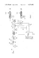
- FIG. 1 is a sectional view taken through a diameter of the choke assembly of the present invention illustrating details of construction
- FIG. 2 is a greatly enlarged, detailed view in section showing how the choke assembly closes for the purposes of illustrating how the flow, with or without particulate matter therein, is choked;
- FIG. 3 is a schematic flow diagram of a hydraulic control apparatus for a choke.
- FIG. 4 is an alternate embodiment showing modified mounting of the movable components in the choke assembly.
- the choke of the present invention is identified by the numeral 10 and incorporates an elongate, tubular body 12.
- the body 12 is closed at one end by a plug 14 which is joined to the body 12 at a set of threads 16.
- the plug is provided with a pair of drilled openings 18 to enable it to be grasped by a spanner wrench to be removed.
- the plug is axially drilled with a passage 20 which passage is exposed to the exterior at a threaded opening 22 to enable it to be connected with a fluid line terminating in an appropriate threaded fitting.
- Pressurized fluid at a selected pressurized level is introduced through the passage 20 and fills a chamber 24.
- the chamber 24 is pressurized to a desired level for reasons to be set forth.
- the plug defines one end of the chamber 24, and a piston is received therein.
- the piston has a surrounding seal 28 which seals against leakage along the piston wall 30.
- the piston wall 30 terminates at a shoulder 32.
- the piston as shown is equipped with a protruding surrounding shoulder or extension 34.
- the extension 34 in conjunction with the facing shoulder 32, defines a circular chamber acting on the backside of the piston.
- a passage 36 which is appropriately tapped with threads is formed in the wall of the housing 12. This enables pressurized fluid to be introduced.
- the piston thus is made double acting by selectively introducing pressurized fluid on both faces thereof. It will be appreciated that the surface area of the shoulder 34 is less than the exposed space in the chamber 24, and, accordingly, a higher pressure is required to pressurize the piston from the left.
- the piston extends into an axial passage 38 of reduced diameter.
- O-rings 40 serve as seals preventing leakage. To the left of the seals 40, the piston is exposed to the mud flow. To the right of the seals 40, it is exposed to the fluid introduced under pressure. This is the fluid for actuating the choke as will be described.
- the numeral 42 identifies a laterally extending passage which is a port for the introduction of mud at high pressure. It is the inlet port for the choke 10.
- the opening 42 is encircled by a groove 44.
- the groove 44 receives a seal ring.
- the seal ring is clamped against a fitting which is connected to the passage.
- the fitting itself, is preferably equipped with a flange which has a number of bolt holes drilled in it which match the location of the tapped openings 46. These enable the flange to be bolted to the body 12, the body being provided with a flat face in the vicinity of the port 42.
- the numeral 48 identifies a sleeve which is affixed to a central plug on one end of the piston 26.
- the sleeve 48 is the valve element for closure of the choke. It will be observed that the sleeve 48 is symmetrically constructed at the right and left-hand ends. It is hollow to fit over the circular appendage affixed to the piston 26.
- the sleeve 48 is preferably formed of a hardened metal, such as tungsten carbide particles embedded in a base material. It is made wear resistant. It is equipped with a tapered leading edge. It is axially hollow. This enables it to be reversed on installation. It is for this reason that the right and left-hand ends are identical.
- the sleeve 48 is fastened in place by a bolt 50.
- the bolt 50 threads axially into a tapped opening formed in the piston 26 for that purpose.
- the bolt itself, seats into a cup-shaped washer 52.
- the washer 52 has an encircling shoulder which clamps the sleeve 48 in place.
- the sleeve 48 at each end, is undercut with a shoulder which enables the shoulder to receive the washer 52 to lock the sleeve in place.
- the sleeve 48 is jammed against a transverse shoulder 54 at the exposed face of the piston. This limits its travel. As a consequence, the components are assembled and held in position for operation in the manner to be described.
- the sleeve 48 serves as a valve element. It is positioned against a valve seat which is a removable insert indicated by the numeral 56.
- the valve seat 56 is a hollow sleeve. It is symmetrically shaped at the right and left-hand ends. At the left-hand end, it abuts a shoulder 58. At the right-hand end, a snap ring 60 is used to lock it into position. The snap ring 60 is received in a groove. The snap ring locks the sleeve against the shoulder 58.
- the seat 56 is formed of hardened material, including tungsten carbide. The tungsten carbide material is embedded as small particles in a supporting base metal which is, itself, a hard alloy.
- the seat 56 fits snugly in an axial passage extending from the enlarged chamber communicated with the port 42.
- the sleeve is provided with tapered faces 62 at each end.
- the tapered face serves as a valve seat which operates in conjunction with a shoulder 64 to receive and seal on movement of the tapered plug 48 against the seat.
- the precise manner of sealing is described later.
- the sealing action is self-cleaning, as will be described. This chokes off flow through the assembly 10. In the illustrated position, the valve element 48 is spaced from the valve.
- the seat 56 is reversible.
- the sleeve is easily reversed by removing the snap ring 60 and sliding the sleeve out, reversing it and restoring it to the seated position shown in FIG. 1.
- the bulk of the wear occurs at the upstream end, and very little wear occurs at the downstream end. It is for this reason that the sleeve can be reversed periodically to enable the device to have extended life.
- the seat 56 locks against a downstream shoulder 58 as described. This limits its travel and specifies its location. This enables the sleeve to remain stationary as the piston 26 telescopes into the area adjacent to the sleeve bringing the valve element 48 towards a sealing or choking position. It will be understood that the valve element 48 is not always closed against the valve seat 56, but, rather, it is moved to a spaced location constricting flow. When the flow is constricted, the flow is choked by the valve in a manner determined by the operator.
- the left-hand end of the body 12 is axially drilled with a passage, and an internal groove is formed for receiving a snap ring 68.
- the snap ring 68 holds in position an internal sleeve 70.
- the sleeve 70 is the downstream outlet sleeve of the apparatus.
- the body device terminates at a face 72 which is grooved at 74 to receive a seal ring.
- a surrounding flange 76 enables it to be connected with a mating flange constructed according to industry standards, and suitable holes are provided on a bolt circle to enable the body 12 to be joined to the connective apparatus.
- the sleeve 70 is made of a hardened material, but it does not have to be as hard as the material used in the seat 56. It is also made thinner. At this point in the choke, the flow of mud is basically axial. Therefore, the sleeve 70 is not exposed to the brunt of the abrasive action which normally occurs in the valve apparatus.
- the device is connected in a mud line by affixing the inlet line to the port 42, and an outlet line is connected to the flange 76 at the left-hand end of the equipment.
- fluid control lines are connected to the threaded and tapped openings 22 and 36.
- a convenient technique is to connect a pressure accumulator topped with a gas (sometimes over a liquid) to the tapped opening 36. When a suitable hydraulic pressure is introduced through the opening 22, the piston is forced to the left. When that pressure is reduced, the accumulator controls the pressure on the piston to force the piston to the end of its movement. Moreover, this is a fail safe apparatus; should the fluid pressure at the fitting 22 be lost for any reason whatsoever, the piston slams wide open.
- valve element and the valve seat jointly have facing tapered edges. As they close to a gap which might pinch or clamp on a sand particle, the seat and valve element open to a wide gap downstream.
- any throttling which occurs is between a pair of concentric, tapered surfaces which are aptly suited for long wear. The wear which does occur is limited because the choked flow is, in fact, almost parallel to the tapered faces through a gap defined by the tapered faces.
- Full closure is achieved at the facing perpendicular seats. They are fairly well protected from the flow by the position of the valve and seat in the choke position. As the valve is closed toward the seat, the tapered, opposing surfaces 62 and 110 come toward one another. They close flow, and, if sand particles can get into the gap during closure, the wider gap between facing perpendicular faces is flushed to wash away the debris. Large particles are blocked upstream of the tapered faces and do not enter the seat area when the plug enters the seat area. The valve element thus chokes mud flow upstream of the seating surfaces. Full closure is obtained on flat, facial contact, free of sand particles and the like.
- the valve element thus does not close fully and does not fully constrict on its outer cylindrical surface until the mud-borne particles are flushed out of the space between the facing perpendicular shoulders by the jetted flow through the tapered faces.
- the sleeve 48 enters fully within the seat 56 to seat and seal. This requires that the tapered end portion 110 of the valve telescope into the seat for closure by contacting the perpendicular faces 64 and 112 together.
- the valve has maximum diameter sliding into the seat, itself, to plug and close the valve seat area.
- Mud flow is introduced through the passage 42. It impinges directly on the sleeve 48.
- the mud is highly abrasive and tends to wear the sleeve, but the wear is resisted by the use of an extremely hard material in the sleeve.
- the mud flow if diverted to the left and out through the axial passage.
- the flow of mud is through the controlled gap between the sleeve 48 which serves as a valve element and the seat 56 which serves as a valve seat.
- the position of the element 48 is thus controlled by the movement of the piston to regulate or choke the flow.
- the apparatus 10 serves its intended purpose. More importantly, it has extended life.
- the wear is basically localized in the sleeve 48 and the seat 56.
- the two replaceable sleeves are, for this reason, made of hard materials and are replaceable.
- the apparatus can be disassembled quickly and easily and the sleeves reversed. They are provided with duplicate ends. The worn end is switched away from the point of wear, the point of wear being the facing surface for the valve element and the valve seat.
- FIG. 2 is a very enlarged view of the components as they come together.
- the sleeve 48 is shown in enlarged view.
- the enlarged view of the sleeve 48 positioned in the removable insert 56 depicts how closure is achieved. Attention is directed to three particular areas which disclose unique features. First of all, immediately prior to full closure, the flow of mud through the funnel-shaped area 80 permits mud, but not particles, to flow into the slot between the two components. Immediately prior to full shut-off, such mud flow is funneled into a narrow constriction. The mud, itself, will flow through this funnel-shaped area 80 and into the constricted passage. Particles in the mud of a size to cause damage will not enter the passage because they will not pass through the narrow passage. More than an adequate flow of mud gets into the passage and flows under pressure to flush out any particles in transit through the passage.
- Mud flow is thus introduced from the funnel-shaped area 80 and fully surrounds the sleeve 48, flowing into the narrow, slotted passage 82.
- the passage 82 is, in fact, a narrow, constricted passage. It has a clearance sufficient that the mud flowing through it is able to flush out any particles that might have been caught in the passage area 82 prior to closure of the components.
- the passage is about 0.002 to 0.004 inches in width and has the form of a complete circle.
- the numeral 84 identifies a third area. This flow area is between the perpendicular facing shoulders 64 and 112 on the two components.
- the area 84 is flushed by the flow from the concentric passage 82. As an example, if a piece of particulate trash is caught in the passage 84 during closure, it is flushed away. This is achieved during closing movement of the plug valve mechanism.
- the passage 84 is wider than the passage 82.
- the passage 82 is limited or fixed in width during the time the passage 84 is being narrowed in width. This means that no new particles are being introduced into the passage 84. As the components move closer together so that the passage 84 narrows, when it becomes more narrow, additional particles are not introduced because they are caught at the funnel 80.
- FIG. 2 thus discloses an arrangement whereby flushing of particles is achieved at the instant before closure.
- Closure itself, has a self-cleaning operation.
- the flow capacity through the passage 82 is approximately constant, presuming that a constant pressure head is maintained upstream.
- the passage 84 is closed, the velocity through it increases prior to cutoff.
- the effective cross-sectional area of the passage 84 is reduced toward zero, the flow rate increases to thereby provide enhanced scavenging and cleaning so that all particles are removed.
- the net result is that the faces 64 and 112 which come together in the passage 84 are flushed clean the instant before closure.
- the procedure described above is most effective in closing the two components together with a reduced wear rate. Wear is encountered as a result of the abrasive nature of the particles carried in the drilling mud.
- the sleeve 48 is preferably chamfered at its corner 110. If it is chamfered, it creates a flow cavity at 86 of redirected velocity. As the flow enters this area, it must turn, but it is turning in a larger area, and, accordingly, the velocity drops somewhat to enable the flow to turn. As the velocity drops, erosion of the components at this area is reduced. Accordingly, the sleeve is chamfered to enlarge the cavity 86, and the insert 56 has an internal corner which is rounded, as shown in FIG. 2, to some desired radius. This protects the corner of both components against erosion. The flow area 86 thus accommodates a turn of the flow with minimum damage to the components, and this, thereby, prolongs the life of the equipment.
- the faces 64 and 112 in the passage 84 be ground and lapped so that they are parallel and able to form a metal-to-metal seal.
- Dimensional control to maintain the circular passage 82 is also preferred. It is, thus, desirable that the movable components be axially aligned concentric relative to the fixed, central components.
- FIG. 4 is an alternate embodiment of the disclosed invention incorporating an end plate 90.
- the end plate 90 prevents abrasion or wear which might otherwise impinge on the end of the apparatus shown in FIG. 1. Again, this is desirable to prevent substantial damage to the device.
- the end plate 90 is very useful in the prevention of wear and damage and provides longer life.
- FIG. 4 further differs in that a central mounting bolt is not used. Rather, an encircling, spacer lock ring 92 is placed at the back of the sleeve 48, and a pin or set screw passes through the spacer ring at 94. This locks the ring. This is an alternate method of assembly. The use of a spacer ring is helpful to provide pressure against the face of the removable sleeve 48 fully surrounding its circumference.
- FIG. 3 of the drawings should be considered next.
- FIG. 3 discloses a system for operation of the equipment.
- alternate mud chokes are shown.
- a power system for their operation is also depicted.
- a pneumatically powered system is shown, although other systems can be used.
- An air powered hydraulic pump operates the choke with oil from a reservoir.
- An air supply line connects through a filter.
- the line is identified by the numeral 100 and is connected to a filter 102 which, in turn, is connected to a pressure regulator valve 104.
- Suitable quantities of lubricating oil are introduced at 106, and pressure gauges are found at 108 and 110.
- the pressure gauges 108 and 110 provide the operator with an indication of pressure levels.
- the lubricator delivers air under pressure to one side of a diaphragm pump mechanism.
- the diaphragm operated, air driven pump mechanism 112 is in a hydraulic circuit to force regulated pressure to a choke.
- the hydraulic circuit includes an emergency pump 116.
- the pump 116 is an emergency hand powered high pressure oil pump connected to a filter 118 which, in turn, connects to a line 120 which, in turn, passes through a control valve 122.
- the valve 122 is a two-position, four-way valve. It is provided with a high pressure inlet line. Additionally, it provides an alternate line to a sump, the sump being indicated at 124. The sump line is 126.
- the reservoir 124 is maintained at minimum pressure, ordinarily atmospheric pressure. System pressure is adjusted by operation of the regulator 130, which, in turn, controls the hydraulic oil pressure to the chokes. This regulator 130 is connected to the two-position valve 122.
- Most mud pump systems include duplex pumps and two or more pumps connected to a duplex choke arrangement. Two such chokes are shown symbolically in FIG. 3 of the drawings. The two chokes are used selectively and alternately, depending on the mud flow. It is desirable to always have a back-up choke.
- the chokes shown in FIG. 3 are preferably the chokes depicted in the present disclosure, and each one has a hydraulically driven piston in it, as previously stated.
- a pressure accumulator 134 can be used to provide a return force for operation of the chokes.
- the pressure accumulator is partly filled with incompressible fluid and partly with compressible air or some other gas so that a return stroke can be effected even should all the pneumatic or hydraulic equipment fail. Ordinarily, it is better to have the device move to an open position on failure.
- the illustrated system provides operative power to the mud chokes, particularly when installed in a duplex system.
- the open choke can be modulated by varying the position of the movable element 48 in response to the regulator valve 130.
Abstract
Description
Claims (10)
Priority Applications (4)
| Application Number | Priority Date | Filing Date | Title |
|---|---|---|---|
| US06/018,508 US4257442A (en) | 1976-09-27 | 1979-03-08 | Choke for controlling the flow of drilling mud |
| CA343,105A CA1105921A (en) | 1979-03-08 | 1980-01-04 | Choke for controlling the flow of drilling mud |
| DE8080100173T DE3067598D1 (en) | 1979-03-08 | 1980-01-15 | Choke for controlling the flow of drilling mud |
| EP80100173A EP0016304B1 (en) | 1979-03-08 | 1980-01-15 | Choke for controlling the flow of drilling mud |
Applications Claiming Priority (2)
| Application Number | Priority Date | Filing Date | Title |
|---|---|---|---|
| US05/727,031 US4190073A (en) | 1976-09-27 | 1976-09-27 | Choke for controlling the flow of drilling mud |
| US06/018,508 US4257442A (en) | 1976-09-27 | 1979-03-08 | Choke for controlling the flow of drilling mud |
Related Parent Applications (1)
| Application Number | Title | Priority Date | Filing Date |
|---|---|---|---|
| US05/727,031 Continuation-In-Part US4190073A (en) | 1976-09-27 | 1976-09-27 | Choke for controlling the flow of drilling mud |
Publications (1)
| Publication Number | Publication Date |
|---|---|
| US4257442A true US4257442A (en) | 1981-03-24 |
Family
ID=26691192
Family Applications (1)
| Application Number | Title | Priority Date | Filing Date |
|---|---|---|---|
| US06/018,508 Expired - Lifetime US4257442A (en) | 1976-09-27 | 1979-03-08 | Choke for controlling the flow of drilling mud |
Country Status (1)
| Country | Link |
|---|---|
| US (1) | US4257442A (en) |
Cited By (70)
| Publication number | Priority date | Publication date | Assignee | Title |
|---|---|---|---|---|
| US4355784A (en) * | 1980-08-04 | 1982-10-26 | Warren Automatic Tool Company | Method and apparatus for controlling back pressure |
| US4470430A (en) * | 1981-05-26 | 1984-09-11 | Lancaster Robert D | Drilling choke |
| US4680965A (en) * | 1984-11-29 | 1987-07-21 | Weitmann & Konrad Gmbh & Co. Kg | Process for continuous density measurement |
| US4737082A (en) * | 1986-01-31 | 1988-04-12 | Stal Refrigeration Ab | Lift valve for rotary screw compressors |
| US5040733A (en) * | 1989-06-01 | 1991-08-20 | Allen Ernest W | Air driven hydraulic spraying system |
| US5307872A (en) * | 1993-04-08 | 1994-05-03 | Texaco Inc. | Automatic choke |
| US5762316A (en) * | 1995-10-04 | 1998-06-09 | Kraft Foods, Inc. | Valve mechanism with improved sealing |
| WO1998055729A1 (en) * | 1997-06-04 | 1998-12-10 | Weatherford/Lamb, Inc. | Valve for use in a wellbore |
| US6390442B2 (en) * | 2000-01-06 | 2002-05-21 | Smc Corporation | Two-port valve |
| US6412554B1 (en) | 2000-03-14 | 2002-07-02 | Weatherford/Lamb, Inc. | Wellbore circulation system |
| US20020189863A1 (en) * | 1999-12-22 | 2002-12-19 | Mike Wardley | Drilling bit for drilling while running casing |
| GB2377982A (en) * | 2001-04-25 | 2003-01-29 | Donald Stuart Miller | Valve with hardened parts for controlling flow of abrasive particles in a carrier fluid |
| US6598501B1 (en) | 1999-01-28 | 2003-07-29 | Weatherford/Lamb, Inc. | Apparatus and a method for facilitating the connection of pipes |
| US20030164251A1 (en) * | 2000-04-28 | 2003-09-04 | Tulloch Rory Mccrae | Expandable apparatus for drift and reaming borehole |
| US20030164276A1 (en) * | 2000-04-17 | 2003-09-04 | Weatherford/Lamb, Inc. | Top drive casing system |
| US20030217865A1 (en) * | 2002-03-16 | 2003-11-27 | Simpson Neil Andrew Abercrombie | Bore lining and drilling |
| US6655651B2 (en) * | 2000-03-27 | 2003-12-02 | Smc Corporation | Two-port valve |
| US20030221519A1 (en) * | 2000-03-14 | 2003-12-04 | Haugen David M. | Methods and apparatus for connecting tubulars while drilling |
| US20040003490A1 (en) * | 1997-09-02 | 2004-01-08 | David Shahin | Positioning and spinning device |
| US20040011531A1 (en) * | 1998-12-24 | 2004-01-22 | Weatherford/Lamb, Inc. | Apparatus and method for facilitating the connection of tubulars using a top drive |
| US6684737B1 (en) | 1999-01-28 | 2004-02-03 | Weatherford/Lamb, Inc. | Power tong |
| US20040045717A1 (en) * | 2002-09-05 | 2004-03-11 | Haugen David M. | Method and apparatus for reforming tubular connections |
| US20040069500A1 (en) * | 2001-05-17 | 2004-04-15 | Haugen David M. | Apparatus and methods for tubular makeup interlock |
| US6745646B1 (en) | 1999-07-29 | 2004-06-08 | Weatherford/Lamb, Inc. | Apparatus and method for facilitating the connection of pipes |
| US20040108142A1 (en) * | 1994-10-14 | 2004-06-10 | Weatherford/Lamb, Inc. | Methods and apparatus for cementing drill strings in place for one pass drilling and completion of oil and gas wells |
| US20040112603A1 (en) * | 2002-12-13 | 2004-06-17 | Galloway Gregory G. | Apparatus and method of drilling with casing |
| US20040124011A1 (en) * | 2002-12-31 | 2004-07-01 | Gledhill Andrew D. | Expandable bit with a secondary release device |
| US20040124010A1 (en) * | 2002-12-30 | 2004-07-01 | Galloway Gregory G. | Drilling with concentric strings of casing |
| US20040123984A1 (en) * | 1994-10-14 | 2004-07-01 | Weatherford/Lamb, Inc. | Methods and apparatus for cementing drill strings in place for one pass drilling and completion of oil and gas wells |
| US20040173357A1 (en) * | 1998-08-24 | 2004-09-09 | Weatherford/Lamb, Inc. | Apparatus for connecting tublars using a top drive |
| US20040194965A1 (en) * | 1998-12-24 | 2004-10-07 | Weatherford/Lamb, Inc. | Apparatus and method for facilitating the connection of tubulars using a top drive |
| US6814149B2 (en) | 1999-11-26 | 2004-11-09 | Weatherford/Lamb, Inc. | Apparatus and method for positioning a tubular relative to a tong |
| US20040226751A1 (en) * | 2003-02-27 | 2004-11-18 | Mckay David | Drill shoe |
| US20040237726A1 (en) * | 2002-02-12 | 2004-12-02 | Schulze Beckinghausen Joerg E. | Tong |
| US20040251055A1 (en) * | 2002-07-29 | 2004-12-16 | Weatherford/Lamb, Inc. | Adjustable rotating guides for spider or elevator |
| US20040251050A1 (en) * | 1997-09-02 | 2004-12-16 | Weatherford/Lamb, Inc. | Method and apparatus for drilling with casing |
| US6854533B2 (en) | 2002-12-20 | 2005-02-15 | Weatherford/Lamb, Inc. | Apparatus and method for drilling with casing |
| US6868906B1 (en) | 1994-10-14 | 2005-03-22 | Weatherford/Lamb, Inc. | Closed-loop conveyance systems for well servicing |
| US20050061112A1 (en) * | 2003-09-19 | 2005-03-24 | Weatherford Lamb, Inc. | Adapter frame for a power frame |
| US20050076744A1 (en) * | 2003-10-08 | 2005-04-14 | Weatherford/Lamb, Inc. | Apparatus and methods for connecting tubulars |
| US20050077743A1 (en) * | 2003-10-08 | 2005-04-14 | Bernd-Georg Pietras | Tong assembly |
| US6896075B2 (en) | 2002-10-11 | 2005-05-24 | Weatherford/Lamb, Inc. | Apparatus and methods for drilling with casing |
| US20050269105A1 (en) * | 1998-07-22 | 2005-12-08 | Weatherford/Lamb, Inc. | Apparatus for facilitating the connection of tubulars using a top drive |
| US20060000600A1 (en) * | 1998-08-24 | 2006-01-05 | Bernd-Georg Pietras | Casing feeder |
| US20060065868A1 (en) * | 2004-09-28 | 2006-03-30 | Strong Warren N | Diaphragm valve |
| US7028586B2 (en) | 2000-02-25 | 2006-04-18 | Weatherford/Lamb, Inc. | Apparatus and method relating to tongs, continous circulation and to safety slips |
| US7028585B2 (en) | 1999-11-26 | 2006-04-18 | Weatherford/Lamb, Inc. | Wrenching tong |
| US20060086538A1 (en) * | 2002-07-08 | 2006-04-27 | Shell Oil Company | Choke for controlling the flow of drilling mud |
| US20060151181A1 (en) * | 2005-01-12 | 2006-07-13 | David Shahin | One-position fill-up and circulating tool |
| US7090254B1 (en) | 1999-04-13 | 2006-08-15 | Bernd-Georg Pietras | Apparatus and method aligning tubulars |
| US20060180315A1 (en) * | 2005-01-18 | 2006-08-17 | David Shahin | Top drive torque booster |
| US20060266973A1 (en) * | 2003-06-18 | 2006-11-30 | Colin Gladwell | Seal arrangement |
| US20070193751A1 (en) * | 1998-08-24 | 2007-08-23 | Bernd-Georg Pietras | Casing running and drilling system |
| US20070251701A1 (en) * | 2006-04-27 | 2007-11-01 | Michael Jahn | Torque sub for use with top drive |
| US20080059073A1 (en) * | 2000-04-17 | 2008-03-06 | Giroux Richard L | Methods and apparatus for handling and drilling with tubulars or casing |
| US7353880B2 (en) | 1998-08-24 | 2008-04-08 | Weatherford/Lamb, Inc. | Method and apparatus for connecting tubulars using a top drive |
| US20080125876A1 (en) * | 2006-11-17 | 2008-05-29 | Boutwell Doyle F | Top drive interlock |
| US20090008594A1 (en) * | 2005-11-12 | 2009-01-08 | Jens Burmester | Double seat valve |
| US7650944B1 (en) | 2003-07-11 | 2010-01-26 | Weatherford/Lamb, Inc. | Vessel for well intervention |
| WO2010093691A1 (en) * | 2009-02-11 | 2010-08-19 | M-I L.L.C. | Autochoke system |
| US7874352B2 (en) | 2003-03-05 | 2011-01-25 | Weatherford/Lamb, Inc. | Apparatus for gripping a tubular on a drilling rig |
| USRE42877E1 (en) | 2003-02-07 | 2011-11-01 | Weatherford/Lamb, Inc. | Methods and apparatus for wellbore construction and completion |
| US20150226337A1 (en) * | 2014-02-10 | 2015-08-13 | Cameron International Corporation | In-line control valve |
| US9328558B2 (en) | 2013-11-13 | 2016-05-03 | Varel International Ind., L.P. | Coating of the piston for a rotating percussion system in downhole drilling |
| US9404342B2 (en) | 2013-11-13 | 2016-08-02 | Varel International Ind., L.P. | Top mounted choke for percussion tool |
| US9415496B2 (en) | 2013-11-13 | 2016-08-16 | Varel International Ind., L.P. | Double wall flow tube for percussion tool |
| US9562392B2 (en) | 2013-11-13 | 2017-02-07 | Varel International Ind., L.P. | Field removable choke for mounting in the piston of a rotary percussion tool |
| NO341017B1 (en) * | 2016-05-12 | 2017-08-07 | Safelink As | High pressure gas valve |
| US20170343119A1 (en) * | 2016-05-31 | 2017-11-30 | Cameron International Corporation | Choke plug tip |
| US11125049B2 (en) | 2017-01-23 | 2021-09-21 | Cameron Technologies Limited | Superhard material enhanced choke cage |
Citations (8)
| Publication number | Priority date | Publication date | Assignee | Title |
|---|---|---|---|---|
| US662249A (en) * | 1899-11-07 | 1900-11-20 | Alexander W Cadman | Valve. |
| US855517A (en) * | 1906-05-16 | 1907-06-04 | Albert K Shauck | Valve. |
| US1006564A (en) * | 1909-03-01 | 1911-10-24 | Samuel A Kinsey Jr | Valve. |
| US1193849A (en) * | 1916-08-08 | George h | ||
| US1202044A (en) * | 1915-11-18 | 1916-10-24 | Nellie Fisher | Valve. |
| US2634754A (en) * | 1948-12-27 | 1953-04-14 | Oil Ct Tool Company | Pilot controlled fluid pressure operated valve |
| US3064675A (en) * | 1960-02-08 | 1962-11-20 | Fisher Governor Co | High pressure regulator |
| US3703908A (en) * | 1971-07-26 | 1972-11-28 | Us Air Force | Squirt cleaning poppet valve and seat |
-
1979
- 1979-03-08 US US06/018,508 patent/US4257442A/en not_active Expired - Lifetime
Patent Citations (8)
| Publication number | Priority date | Publication date | Assignee | Title |
|---|---|---|---|---|
| US1193849A (en) * | 1916-08-08 | George h | ||
| US662249A (en) * | 1899-11-07 | 1900-11-20 | Alexander W Cadman | Valve. |
| US855517A (en) * | 1906-05-16 | 1907-06-04 | Albert K Shauck | Valve. |
| US1006564A (en) * | 1909-03-01 | 1911-10-24 | Samuel A Kinsey Jr | Valve. |
| US1202044A (en) * | 1915-11-18 | 1916-10-24 | Nellie Fisher | Valve. |
| US2634754A (en) * | 1948-12-27 | 1953-04-14 | Oil Ct Tool Company | Pilot controlled fluid pressure operated valve |
| US3064675A (en) * | 1960-02-08 | 1962-11-20 | Fisher Governor Co | High pressure regulator |
| US3703908A (en) * | 1971-07-26 | 1972-11-28 | Us Air Force | Squirt cleaning poppet valve and seat |
Cited By (122)
| Publication number | Priority date | Publication date | Assignee | Title |
|---|---|---|---|---|
| US4355784A (en) * | 1980-08-04 | 1982-10-26 | Warren Automatic Tool Company | Method and apparatus for controlling back pressure |
| US4470430A (en) * | 1981-05-26 | 1984-09-11 | Lancaster Robert D | Drilling choke |
| US4680965A (en) * | 1984-11-29 | 1987-07-21 | Weitmann & Konrad Gmbh & Co. Kg | Process for continuous density measurement |
| US4737082A (en) * | 1986-01-31 | 1988-04-12 | Stal Refrigeration Ab | Lift valve for rotary screw compressors |
| US5040733A (en) * | 1989-06-01 | 1991-08-20 | Allen Ernest W | Air driven hydraulic spraying system |
| US5307872A (en) * | 1993-04-08 | 1994-05-03 | Texaco Inc. | Automatic choke |
| US6868906B1 (en) | 1994-10-14 | 2005-03-22 | Weatherford/Lamb, Inc. | Closed-loop conveyance systems for well servicing |
| US20040123984A1 (en) * | 1994-10-14 | 2004-07-01 | Weatherford/Lamb, Inc. | Methods and apparatus for cementing drill strings in place for one pass drilling and completion of oil and gas wells |
| US20040108142A1 (en) * | 1994-10-14 | 2004-06-10 | Weatherford/Lamb, Inc. | Methods and apparatus for cementing drill strings in place for one pass drilling and completion of oil and gas wells |
| US5762316A (en) * | 1995-10-04 | 1998-06-09 | Kraft Foods, Inc. | Valve mechanism with improved sealing |
| WO1998055729A1 (en) * | 1997-06-04 | 1998-12-10 | Weatherford/Lamb, Inc. | Valve for use in a wellbore |
| US20040003490A1 (en) * | 1997-09-02 | 2004-01-08 | David Shahin | Positioning and spinning device |
| US20040251050A1 (en) * | 1997-09-02 | 2004-12-16 | Weatherford/Lamb, Inc. | Method and apparatus for drilling with casing |
| US20050269105A1 (en) * | 1998-07-22 | 2005-12-08 | Weatherford/Lamb, Inc. | Apparatus for facilitating the connection of tubulars using a top drive |
| US20070074876A1 (en) * | 1998-07-22 | 2007-04-05 | Bernd-Georg Pietras | Apparatus for facilitating the connection of tubulars using a top drive |
| US7665531B2 (en) | 1998-07-22 | 2010-02-23 | Weatherford/Lamb, Inc. | Apparatus for facilitating the connection of tubulars using a top drive |
| US7353880B2 (en) | 1998-08-24 | 2008-04-08 | Weatherford/Lamb, Inc. | Method and apparatus for connecting tubulars using a top drive |
| US7513300B2 (en) | 1998-08-24 | 2009-04-07 | Weatherford/Lamb, Inc. | Casing running and drilling system |
| US20070193751A1 (en) * | 1998-08-24 | 2007-08-23 | Bernd-Georg Pietras | Casing running and drilling system |
| US20060000600A1 (en) * | 1998-08-24 | 2006-01-05 | Bernd-Georg Pietras | Casing feeder |
| US20040173357A1 (en) * | 1998-08-24 | 2004-09-09 | Weatherford/Lamb, Inc. | Apparatus for connecting tublars using a top drive |
| US7669662B2 (en) | 1998-08-24 | 2010-03-02 | Weatherford/Lamb, Inc. | Casing feeder |
| US7451826B2 (en) | 1998-08-24 | 2008-11-18 | Weatherford/Lamb, Inc. | Apparatus for connecting tubulars using a top drive |
| US20070051519A1 (en) * | 1998-08-24 | 2007-03-08 | Bernd-Georg Pietras | apparatus for connecting tubulars using a top drive |
| US20040011531A1 (en) * | 1998-12-24 | 2004-01-22 | Weatherford/Lamb, Inc. | Apparatus and method for facilitating the connection of tubulars using a top drive |
| US20060011353A1 (en) * | 1998-12-24 | 2006-01-19 | Weatherford/Lamb, Inc. | Apparatus and methods for facilitating the connection of tubulars using a top drive |
| US20040194965A1 (en) * | 1998-12-24 | 2004-10-07 | Weatherford/Lamb, Inc. | Apparatus and method for facilitating the connection of tubulars using a top drive |
| US6684737B1 (en) | 1999-01-28 | 2004-02-03 | Weatherford/Lamb, Inc. | Power tong |
| US6598501B1 (en) | 1999-01-28 | 2003-07-29 | Weatherford/Lamb, Inc. | Apparatus and a method for facilitating the connection of pipes |
| US7090254B1 (en) | 1999-04-13 | 2006-08-15 | Bernd-Georg Pietras | Apparatus and method aligning tubulars |
| US6745646B1 (en) | 1999-07-29 | 2004-06-08 | Weatherford/Lamb, Inc. | Apparatus and method for facilitating the connection of pipes |
| US20060179980A1 (en) * | 1999-11-26 | 2006-08-17 | Weatherford/Lamb, Inc. | Wrenching tong |
| US7028585B2 (en) | 1999-11-26 | 2006-04-18 | Weatherford/Lamb, Inc. | Wrenching tong |
| US6814149B2 (en) | 1999-11-26 | 2004-11-09 | Weatherford/Lamb, Inc. | Apparatus and method for positioning a tubular relative to a tong |
| US7861618B2 (en) | 1999-11-26 | 2011-01-04 | Weatherford/Lamb, Inc. | Wrenching tong |
| US20020189863A1 (en) * | 1999-12-22 | 2002-12-19 | Mike Wardley | Drilling bit for drilling while running casing |
| US6390442B2 (en) * | 2000-01-06 | 2002-05-21 | Smc Corporation | Two-port valve |
| US7028586B2 (en) | 2000-02-25 | 2006-04-18 | Weatherford/Lamb, Inc. | Apparatus and method relating to tongs, continous circulation and to safety slips |
| US7107875B2 (en) | 2000-03-14 | 2006-09-19 | Weatherford/Lamb, Inc. | Methods and apparatus for connecting tubulars while drilling |
| US7028787B2 (en) | 2000-03-14 | 2006-04-18 | Weatherford/Lamb, Inc. | Tong for wellbore operations |
| US20040154835A1 (en) * | 2000-03-14 | 2004-08-12 | Weatherford/Lamb, Inc. | Tong for wellbore operations |
| US6668684B2 (en) | 2000-03-14 | 2003-12-30 | Weatherford/Lamb, Inc. | Tong for wellbore operations |
| US6412554B1 (en) | 2000-03-14 | 2002-07-02 | Weatherford/Lamb, Inc. | Wellbore circulation system |
| US20030221519A1 (en) * | 2000-03-14 | 2003-12-04 | Haugen David M. | Methods and apparatus for connecting tubulars while drilling |
| US6655651B2 (en) * | 2000-03-27 | 2003-12-02 | Smc Corporation | Two-port valve |
| US7793719B2 (en) | 2000-04-17 | 2010-09-14 | Weatherford/Lamb, Inc. | Top drive casing system |
| US7712523B2 (en) | 2000-04-17 | 2010-05-11 | Weatherford/Lamb, Inc. | Top drive casing system |
| US7918273B2 (en) | 2000-04-17 | 2011-04-05 | Weatherford/Lamb, Inc. | Top drive casing system |
| US20030164276A1 (en) * | 2000-04-17 | 2003-09-04 | Weatherford/Lamb, Inc. | Top drive casing system |
| US20080059073A1 (en) * | 2000-04-17 | 2008-03-06 | Giroux Richard L | Methods and apparatus for handling and drilling with tubulars or casing |
| US20080110637A1 (en) * | 2000-04-17 | 2008-05-15 | Randy Gene Snider | Top drive casing system |
| US7654325B2 (en) | 2000-04-17 | 2010-02-02 | Weatherford/Lamb, Inc. | Methods and apparatus for handling and drilling with tubulars or casing |
| US20030164251A1 (en) * | 2000-04-28 | 2003-09-04 | Tulloch Rory Mccrae | Expandable apparatus for drift and reaming borehole |
| GB2377982B (en) * | 2001-04-25 | 2004-12-15 | Donald Stuart Miller | Abrasive fluid jet machining apparatus |
| GB2377982A (en) * | 2001-04-25 | 2003-01-29 | Donald Stuart Miller | Valve with hardened parts for controlling flow of abrasive particles in a carrier fluid |
| US20060169461A1 (en) * | 2001-05-17 | 2006-08-03 | Weatherford/Lamb, Inc. | Apparatus and methods for tubular makeup interlock |
| US8517090B2 (en) | 2001-05-17 | 2013-08-27 | Weatherford/Lamb, Inc. | Apparatus and methods for tubular makeup interlock |
| US7896084B2 (en) | 2001-05-17 | 2011-03-01 | Weatherford/Lamb, Inc. | Apparatus and methods for tubular makeup interlock |
| US20040069500A1 (en) * | 2001-05-17 | 2004-04-15 | Haugen David M. | Apparatus and methods for tubular makeup interlock |
| US7281587B2 (en) | 2001-05-17 | 2007-10-16 | Weatherford/Lamb, Inc. | Apparatus and methods for tubular makeup interlock |
| US20040237726A1 (en) * | 2002-02-12 | 2004-12-02 | Schulze Beckinghausen Joerg E. | Tong |
| US7281451B2 (en) | 2002-02-12 | 2007-10-16 | Weatherford/Lamb, Inc. | Tong |
| US20030217865A1 (en) * | 2002-03-16 | 2003-11-27 | Simpson Neil Andrew Abercrombie | Bore lining and drilling |
| US20060086538A1 (en) * | 2002-07-08 | 2006-04-27 | Shell Oil Company | Choke for controlling the flow of drilling mud |
| US20070240875A1 (en) * | 2002-07-08 | 2007-10-18 | Van Riet Egbert J | Choke for controlling the flow of drilling mud |
| US20060124357A1 (en) * | 2002-07-29 | 2006-06-15 | Weatherford/Lamb, Inc. | Adjustable rotating guides for spider or elevator |
| US7448456B2 (en) | 2002-07-29 | 2008-11-11 | Weatherford/Lamb, Inc. | Adjustable rotating guides for spider or elevator |
| US20040251055A1 (en) * | 2002-07-29 | 2004-12-16 | Weatherford/Lamb, Inc. | Adjustable rotating guides for spider or elevator |
| US20040045717A1 (en) * | 2002-09-05 | 2004-03-11 | Haugen David M. | Method and apparatus for reforming tubular connections |
| US7100697B2 (en) | 2002-09-05 | 2006-09-05 | Weatherford/Lamb, Inc. | Method and apparatus for reforming tubular connections |
| US6896075B2 (en) | 2002-10-11 | 2005-05-24 | Weatherford/Lamb, Inc. | Apparatus and methods for drilling with casing |
| US20040112603A1 (en) * | 2002-12-13 | 2004-06-17 | Galloway Gregory G. | Apparatus and method of drilling with casing |
| US6899186B2 (en) | 2002-12-13 | 2005-05-31 | Weatherford/Lamb, Inc. | Apparatus and method of drilling with casing |
| US20050217858A1 (en) * | 2002-12-13 | 2005-10-06 | Weatherford/Lamb, Inc. | Apparatus and method of drilling with casing |
| US6854533B2 (en) | 2002-12-20 | 2005-02-15 | Weatherford/Lamb, Inc. | Apparatus and method for drilling with casing |
| US20040124010A1 (en) * | 2002-12-30 | 2004-07-01 | Galloway Gregory G. | Drilling with concentric strings of casing |
| US6857487B2 (en) | 2002-12-30 | 2005-02-22 | Weatherford/Lamb, Inc. | Drilling with concentric strings of casing |
| US20040124011A1 (en) * | 2002-12-31 | 2004-07-01 | Gledhill Andrew D. | Expandable bit with a secondary release device |
| US6953096B2 (en) | 2002-12-31 | 2005-10-11 | Weatherford/Lamb, Inc. | Expandable bit with secondary release device |
| USRE42877E1 (en) | 2003-02-07 | 2011-11-01 | Weatherford/Lamb, Inc. | Methods and apparatus for wellbore construction and completion |
| US20040226751A1 (en) * | 2003-02-27 | 2004-11-18 | Mckay David | Drill shoe |
| US8567512B2 (en) | 2003-03-05 | 2013-10-29 | Weatherford/Lamb, Inc. | Apparatus for gripping a tubular on a drilling rig |
| US10138690B2 (en) | 2003-03-05 | 2018-11-27 | Weatherford Technology Holdings, Llc | Apparatus for gripping a tubular on a drilling rig |
| US7874352B2 (en) | 2003-03-05 | 2011-01-25 | Weatherford/Lamb, Inc. | Apparatus for gripping a tubular on a drilling rig |
| US20060266973A1 (en) * | 2003-06-18 | 2006-11-30 | Colin Gladwell | Seal arrangement |
| US7384022B2 (en) * | 2003-06-18 | 2008-06-10 | Knorr-Bremse Rail Systems (Uk) Ltd. | Seal arrangement for a piston valve |
| US7650944B1 (en) | 2003-07-11 | 2010-01-26 | Weatherford/Lamb, Inc. | Vessel for well intervention |
| US20050061112A1 (en) * | 2003-09-19 | 2005-03-24 | Weatherford Lamb, Inc. | Adapter frame for a power frame |
| US7188548B2 (en) | 2003-09-19 | 2007-03-13 | Weatherford/Lamb, Inc. | Adapter frame for a power frame |
| US20050076744A1 (en) * | 2003-10-08 | 2005-04-14 | Weatherford/Lamb, Inc. | Apparatus and methods for connecting tubulars |
| US20050077743A1 (en) * | 2003-10-08 | 2005-04-14 | Bernd-Georg Pietras | Tong assembly |
| US7707914B2 (en) | 2003-10-08 | 2010-05-04 | Weatherford/Lamb, Inc. | Apparatus and methods for connecting tubulars |
| US20060065868A1 (en) * | 2004-09-28 | 2006-03-30 | Strong Warren N | Diaphragm valve |
| US7694744B2 (en) | 2005-01-12 | 2010-04-13 | Weatherford/Lamb, Inc. | One-position fill-up and circulating tool and method |
| US20060151181A1 (en) * | 2005-01-12 | 2006-07-13 | David Shahin | One-position fill-up and circulating tool |
| US7845418B2 (en) | 2005-01-18 | 2010-12-07 | Weatherford/Lamb, Inc. | Top drive torque booster |
| US20060180315A1 (en) * | 2005-01-18 | 2006-08-17 | David Shahin | Top drive torque booster |
| US7845368B2 (en) * | 2005-11-12 | 2010-12-07 | Tuchenhagen Gmbh | Double seat valve |
| US20090008594A1 (en) * | 2005-11-12 | 2009-01-08 | Jens Burmester | Double seat valve |
| JP2009515125A (en) * | 2005-11-12 | 2009-04-09 | トゥヘンハーゲン ゲーエムベーハー | Double seat valve |
| US7905253B2 (en) * | 2005-11-12 | 2011-03-15 | Tuchenhagen Gmbh | Double seat valve |
| US20090044874A1 (en) * | 2005-11-12 | 2009-02-19 | Jens Burmester | Double Seat Valve |
| AU2006312796B2 (en) * | 2005-11-12 | 2012-02-02 | Tuchenhagen Gmbh | Double seat valve |
| JP4934673B2 (en) * | 2005-11-12 | 2012-05-16 | ゲーエーアー トゥヘンハーゲン ゲーエムベーハー | Double seat valve |
| US7757759B2 (en) | 2006-04-27 | 2010-07-20 | Weatherford/Lamb, Inc. | Torque sub for use with top drive |
| US20070251701A1 (en) * | 2006-04-27 | 2007-11-01 | Michael Jahn | Torque sub for use with top drive |
| US7882902B2 (en) | 2006-11-17 | 2011-02-08 | Weatherford/Lamb, Inc. | Top drive interlock |
| US20080125876A1 (en) * | 2006-11-17 | 2008-05-29 | Boutwell Doyle F | Top drive interlock |
| WO2010093691A1 (en) * | 2009-02-11 | 2010-08-19 | M-I L.L.C. | Autochoke system |
| US9341037B2 (en) | 2009-02-11 | 2016-05-17 | M-I L.L.C. | Autochoke system |
| EA023428B1 (en) * | 2009-02-11 | 2016-06-30 | Эм-Ай Эл. Эл. Си. | Autochoke system |
| US9328558B2 (en) | 2013-11-13 | 2016-05-03 | Varel International Ind., L.P. | Coating of the piston for a rotating percussion system in downhole drilling |
| US9404342B2 (en) | 2013-11-13 | 2016-08-02 | Varel International Ind., L.P. | Top mounted choke for percussion tool |
| US9415496B2 (en) | 2013-11-13 | 2016-08-16 | Varel International Ind., L.P. | Double wall flow tube for percussion tool |
| US9562392B2 (en) | 2013-11-13 | 2017-02-07 | Varel International Ind., L.P. | Field removable choke for mounting in the piston of a rotary percussion tool |
| US20150226337A1 (en) * | 2014-02-10 | 2015-08-13 | Cameron International Corporation | In-line control valve |
| US9568109B2 (en) * | 2014-02-10 | 2017-02-14 | Cameron International Corporation | In-line control valve |
| NO341017B1 (en) * | 2016-05-12 | 2017-08-07 | Safelink As | High pressure gas valve |
| NO20160814A1 (en) * | 2016-05-12 | 2017-08-07 | Safelink As | High pressure gas valve |
| US20170343119A1 (en) * | 2016-05-31 | 2017-11-30 | Cameron International Corporation | Choke plug tip |
| US10125875B2 (en) * | 2016-05-31 | 2018-11-13 | Cameron International Corporation | Choke plug tip |
| US11125049B2 (en) | 2017-01-23 | 2021-09-21 | Cameron Technologies Limited | Superhard material enhanced choke cage |
Similar Documents
| Publication | Publication Date | Title |
|---|---|---|
| US4257442A (en) | Choke for controlling the flow of drilling mud | |
| US4850392A (en) | Double poppet relief valve | |
| US4190073A (en) | Choke for controlling the flow of drilling mud | |
| US4355784A (en) | Method and apparatus for controlling back pressure | |
| US5004007A (en) | Chemical injection valve | |
| CA2124676C (en) | Mud check valves in drilling apparatus (wells) | |
| US4446887A (en) | Variable high pressure choke | |
| US5884705A (en) | Equalizing valve seat for a subsurface safety valve | |
| EP0124230A2 (en) | Valve | |
| US3831845A (en) | Fluid delivery system | |
| US4281678A (en) | Throttling mud choke apparatus | |
| US5862833A (en) | Distribution valve for high pressure coolant used in a metalworking machine application | |
| EP0475754B1 (en) | Back pressure regulating valve | |
| CN112997030B (en) | Method and valve including flushing feature | |
| US20060202150A1 (en) | Valve assembly with angled valve guide | |
| US20080078586A1 (en) | Mud systems with pressure relief valve | |
| US4377177A (en) | Throttling mud choke apparatus | |
| US4461316A (en) | Drilling choke | |
| US10508745B2 (en) | Valve assembly | |
| US3508577A (en) | Blowout control valve for drilling well | |
| US4531545A (en) | Drilling choke valve | |
| CA1175317A (en) | Power assisted check valve | |
| US20030062502A1 (en) | Ported slide gate valve with gate motion to break scale build up | |
| CA1105921A (en) | Choke for controlling the flow of drilling mud | |
| US4315616A (en) | Dump valve |
Legal Events
| Date | Code | Title | Description |
|---|---|---|---|
| AS | Assignment |
Owner name: BYLER, GERALD L. MISSOURI CITY, TX Free format text: ASSIGNMENT OF 1/2 OF ASSIGNORS INTEREST;ASSIGNOR:CLAYCOMB, JACK R.;REEL/FRAME:004230/0161 Effective date: 19840226 |
|
| AS | Assignment |
Owner name: CLAYCOMB ENGINEERING, INC., HOUSTON, HARRIS, TX. A Free format text: ASSIGNMENT OF ASSIGNORS INTEREST.;ASSIGNOR:BYLER, GERALD L.;REEL/FRAME:004444/0932 Effective date: 19850812 |
|
| AS | Assignment |
Owner name: CLAYCOMB ENGINEERING, INC., HOUSTON, TX., A CORP. Free format text: ASSIGNMENT OF 1/2 OF ASSIGNORS INTEREST;ASSIGNOR:CLAYCOMB, JACK R.;REEL/FRAME:004458/0512 Effective date: 19850917 |
|
| AS | Assignment |
Owner name: RICKERT PRECISIONS INDUSTRIES, INC. Free format text: A PARTIAL SATISFACTION OF JUDGEMENT, DATED NOVEMBER 9, 1988;ASSIGNOR:CLAYCOMB ENGINEERING INC.;REEL/FRAME:005081/0223 Effective date: 19850917 |