US4288205A - Variable volume peristaltic pump - Google Patents
Variable volume peristaltic pump Download PDFInfo
- Publication number
- US4288205A US4288205A US06/113,331 US11333180A US4288205A US 4288205 A US4288205 A US 4288205A US 11333180 A US11333180 A US 11333180A US 4288205 A US4288205 A US 4288205A
- Authority
- US
- United States
- Prior art keywords
- peristaltic pump
- band
- adjustable band
- flexible conduit
- flexible
- Prior art date
- Legal status (The legal status is an assumption and is not a legal conclusion. Google has not performed a legal analysis and makes no representation as to the accuracy of the status listed.)
- Expired - Lifetime
Links
Images

Classifications
-
- F—MECHANICAL ENGINEERING; LIGHTING; HEATING; WEAPONS; BLASTING
- F04—POSITIVE - DISPLACEMENT MACHINES FOR LIQUIDS; PUMPS FOR LIQUIDS OR ELASTIC FLUIDS
- F04B—POSITIVE-DISPLACEMENT MACHINES FOR LIQUIDS; PUMPS
- F04B43/00—Machines, pumps, or pumping installations having flexible working members
- F04B43/12—Machines, pumps, or pumping installations having flexible working members having peristaltic action
- F04B43/1253—Machines, pumps, or pumping installations having flexible working members having peristaltic action by using two or more rollers as squeezing elements, the rollers moving on an arc of a circle during squeezing
Definitions
- the present invention relates to peristaltic pumps driven by a single speed power source and in particular to peristaltic pumps whose volumetric delivery rate is adjustable.
- a peristaltic pump consists of a flexible tube within a housing having an arcuate chamber where a flexible tube is circumferentially compressed by a series of rollers or an eccentric against the wall of the inner chamber. As the rollers move along the tube, they force fluid through the tube. The displacement of fluid or the delivery rate of a peristaltic pump is determined by the flexible tubing diameter, the motor speed and any gears between the motor and the pump rollers.
- peristaltic pumps have been in use since at least 1891.
- the Burson U.S. Pat. No. 460,944, issued in 1891 shows an example of a peristaltic pump of that period.
- a list of some of the prior art since 1891 showing the general principles of peristaltic pumps is as follows:
- the flexible tubing used in peristaltic pumps is important since it is the heart of the pump and has to sustain stresses from repeated flexing and abrasion due to the repeated contact with the rollers. Under repeated flexing and abrasion the flexible tubing will fail and fracture, causing leakage.
- a characteristically short tubing life is perhaps the most serious drawback to using peristaltic pumps more generally, and has severely limited the range of present applications. This problem has been recognized and explored in a number of prior art patents which attempt to prolong the tubing life by redesigning the tubing.
- Peristaltic pumps have an economic advantage over other types of pumps and the added cost of specifically designed tubing would take away some of this advantage. Further, the tubing of the prior art will eventually fail and need to be replaced. The risk of failure, cost of down time and the replacement cost of the prior art specially designed tubing will detract from the economic advantage that peristaltic pumps have over other pumps.
- the Stanber U.S. Pat. No. 3,583,838 shows a flexible ring 17 in FIG. 2 that seals the roller bearing of the eccentric roller of the pump.
- the ring 17, however, does not actually act as a buffer but acts with the roller in contacting the tubing as described previously.
- the abrupt and highly localized longitudinal stresses resulting in the tubing's wall generally caused by direct roller contact are not avoided.
- the Shlisky U.S. Pat. No. 3,591,319 teaches a conduit protective member between a plurality of rollers and the flexible tubing.
- the flexible conduit protective member in order for the conduit protective member to act as a buffer, the flexible conduit is stretched over the rollers sufficiently for occlusion to take place and for the flexible conduit to lie against the protective member in such frictional engagement so as to prevent wandering and eliminate any longitudinal stretching and abrasion of the flexible conduit.
- the Gelfand U.S. Pat. No. 3,723,030 shows a plurality of tubes, each protected from the rollers by a nylon strip. This protective strip offers minimal protection to the tubing since it merely eliminates the contact with the roller and does not reduce the severity of the stress caused by the rollers.
- the present invention is a variable volume peristaltic pump which can be driven by a single speed power source.
- the peristaltic pump has a housing with an arcuate chamber and a fixed length of flexible wall tubing arranged circumferentially in the arcuate chamber.
- An adjustable band is circumferentially arranged along the flexible conduit holding the conduit against the chamber wall.
- a plurality of rollers are rotatably attached to a rotor coaxially positioned within the arcuate chamber. The rollers engage the adjustable band and compress the flexible tubing against the wall of the arcuate chamber forcing fluid to flow through the flexible tubing.
- the adjustable band is secured to the housing at one end and is attached at the other end to adjusting means for varying the effective length of the adjustable band.
- the effective length of the adjustable band is increased, the flexible tubing is flattened against the arcuate chamber wall, thereby changing the cross-sectional area of the tubing and consequently the volume.
- the capacity of the flexible tubing has correspondingly been changed and the delivery rate of the pump altered.
- Retracting the adjustable band produces the opposite effect, allowing the tubing to increase its cross-sectional area thereby increasing the delivery rate of the pump.
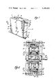
- FIG. 1 is a perspective view of the peristaltic pump of the present invention.
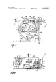
- FIG. 2 is a cross-sectional view taken, with the same portions shown in full for clarity, along the plane 2--2 in FIG. 1.
- FIG. 3 is a front view with certain portions removed for better viewing of the working elements.
- FIG. 4 is a fragmentary top view showing the attachment of the flexible band.
- FIG. 5 is a calibration curve of variable flow rate capability of one embodiment of the peristaltic pump of the present invention.
- FIG. 1 generally shows a peristaltic pump of the present invention with a housing generally indicated at 10.
- the pump housing 10 has an inlet 12 and an outlet 14.
- the pump housing 10 further has a base 16 and a center casing 18 with side wall panels 20 and 22 fixedly attached to each side of the center casing 18 by screw threaded fasteners 24.
- a drive shaft 26 is shown rotatably attached to side walls 20 and 22 and attached at end 28 to a motor (not shown).
- the drive shaft 26 is mounted within a set of bearings 30 which are preferably mounted within side walls 20,22.
- the casing 18 and side walls 20,22 form an arcuate chamber 32, and the rotor 36 is situated coaxially within arcuate chamber 32.
- the rotor 36 is mounted on the drive shaft 26 and the rollers 34 are rotatably mounted by bearings 38 on shafts 40 which are fixedly attached at opposite ends of the rotor 36.
- Each roller 34 is rotatably attached between rotor arms 37.
- An O-ring 39 is situated within relief 41 and acts as a mechanical spring, absorbing variations in manufacturing tolerances within the arcuate chamber 32.
- An adjustable band 52 is circumferentially positioned between the rollers 34 and the flexible conduit 44.
- the adjustable band 52 holds the flexible conduit 44 against the chamber wall 46.
- the adjustable band 52 is pivotally attached to the pump housing 10 at one end 54 and is adjustably (and pivotally) attached to the pump housing 10 at the other end 56 as best seen in FIGS. 3 and 4.
- the end 54 is attached by a screw threaded fastener 58 to a trunnion 60 which is in turn mounted in the pump housing 10.
- the screw threaded fastener 58 holds end 54 by engaging slot 62 and allows the end 54 to oscillate longitudinally within the slot 62 without any transverse movement resulting in minimization of the load on the trunnion 60 when the pump is in operation.
- the adjustable end 56 engages preferably a screw type adjusting clamp 64 which includes an adjusting screw 66 and a body 68 having tabs (not shown) for keeping the adjusting screw 66 within the body 68.
- the clamp 64 is pivotally attached to the pump housing 10 and has a slot through which the adjustable end of the adjustable band 52 is received. A longitudinal section of the threads of adjusting screw 66 is received within the slot and engages grooves 70 of the adjustable end 56. When the adjusting screw 66 is turned, the threads of the screw engage the grooves 70 and move the adjusting end 56 through the slot of the clamp 64, the direction depending on which way the adjusting screw 66 is turned, as indicated by an arrow 71.
- the screw type clamp 64 has a similar mechanical movement to a conventional hose clamp used to secure rubber hoses in an automobile. It should be understood that any conventional means that securely holds the adjusting end 56 and has the capability of allowing infinitely variable adjustments during pump operation may be used without departing from the scope of the present invention.
- the adjustable band 52 is comprised of a stiffening band 52a and a strengthening band 52b.
- the stiffening band 52a is made of a polymer having sufficient fatigue resistance and a sufficient amount of flexibility, preferably polypropylene.
- a creep resistant strengthening band 53b is fixedly attached to the stiffening band 52a on the side engaging the flexible conduit 44 as shown in FIGS. 2 and 3.
- the strengthening band 52a is preferably made of beryllium copper alloys, beryllium nickel alloys or 400 series stainless steel alloys. However, any material having adequate fatigue resistance will suffice. Materials commonly used for coiled and flat springs are most applicable because they have a high endurance limit when compared to other materials. But resiliency is not required of metal band 52b.
- Creep due to tensile forces
- Creep is defined as permanent deformation due to an inability of a stressed member to completely recover its original shape. For example, if plastic is stressed for a prolonged period, molecular bonds will dislocate within the microstructure of the material, causing permanent deformation. Creep in metals is negligible at normal levels of stress. Creep in plastics is a common problem and occurs at very low stress levels.
- the basic purpose of the composite band 52 formed by plastic band 52a and metal band 52b is to maintain an essentially circular spiral during pump operation. It must have a stiffness that provides a gradual curvature within the circumstance of the chamber, thus avoiding excessive contact forces and highly localized tubing stresses.
- the band length and required deflection is defined; and tubing stiffness determines the minimal band rigidity that is desirable.
- the band stiffness is essentially a function of only two variables--the elastic modulus (a material property) and the section modulus (a geometric property of the cross section). Band stiffness is proportional to the product of these elements.
- a metal band could be constructed with the proper stiffness.
- the preferred embodiment of the present invention uses a composite, laminated band construction formed by bands 52a and 52b.
- the relatively thick plastic band 52a provides a large section modulus.
- the low elastic modulus common to plastic materials minimizes internal stresses during flexure and polypropylene is particularly advantageous because of its exceptional fatigue strength.
- the polypropylene band 52a provides the necessary flexural characteristics of stiffness and fatigue life but lacks the necessary tensile requirements of strength and creep resistance.
- the metal band 52b provides those needs.
- the stiffness of the plastic band 52a keeps the radius of curvature of the composite band large during flexure. Because the radius of flexure is large and the thickness of the metal band 52b is small, internal stresses in the metal component are effectively kept below the material endurance limit. At the same time, sufficient tensile strength is available for the attachments at points 56 and 76.
- the plastic and metal bands 52a and 52b reinforce each other while together fulfilling the mechanical demands of pump operation.
- the flexible conduit 44 is situated between the arcuate chamber wall 46 and the strengthening band 52b, being held in place by retaining members 75.
- the spacing between the retaining members 75 is sufficient to accept several tubing sizes.
- the retaining members 75 and the thickness of the plastic band 52a provide a gradual curvature of the adjustable band 52 within the arcuate chamber thereby avoiding any high localized stress to the flexible conduit.
- a pivoting arm 72 is pivotally attached to the pump housing 18 at first pivot point 74 at one end and to the adjustable band 52 at second pivot point 76 at the other end.
- the second pivot point 76 is located directly below the center of the drive shaft 26, and first pivot point 74 is located on the side of the pump housing 10 which is toward the direction of rotation 42 of the rotor 36 as shown in FIG. 3.
- the pivoting arm 72 keeps the flexible band 52 substantially centered within the arcuate chamber 32.
- any net tensile or compressive forces are avoided in the discharge half of the adjustable band 52, defined from the second pivot point 76 to end 54.
- the suction half of the adjustable band, defined from adjustable end 56 to second pivot point 76 is always in a net positive tensile posture, ensuring that buckling of the adjustable band will not occur.
- the net positive tensile force in the adjustment band will also cause the band to be forced away from the flexible conduit.
- any net tensile force in the pivoting arm 72 will always be positive, avoiding any buckling of the pivot arm.
- the pivoting arm 72 effectively contains the adjustment of the adjustable band to the suction side of the pump between the adjusting clamp 64 and the second pivot point 76.
- the function of the discharge portion of the adjustable band is only to provide a continuous roller contact, thereby maintaining a positive seal for an entire revolution of the rollers 34.
- any variations in manufacturing tolerances are easily absorbed by the pivoting arm 72 and the manner of attachment of the end 54 to the trunnion 60.
- the adjustable band 52 serves several purposes.
- the adjustable band 52 protects flexible conduit 44 from the direct contact of the rollers 34 thus avoiding abrasion, and the abrupt and highly localized tensile and shear stresses otherwise caused by direct contact with the rollers and extending the life of the flexible conduit 44.
- the retaining members 75 of the flexible conduit 44 aid in extending the life of flexible conduit 44 by retaining the flexible conduit 44 within the protection of the adjustable band 52.
- retaining members 75 prevent any twisting of the flexible conduit 44 which would otherwise occur if the flexible conduit 44 was allowed movement in the axial direction.
- the preferred combination of the metal band 52b and the polypropylene band 52a add to the life of the adjustable band 52 while also providing a sufficient buffer for protecting the flexible conduit 44 from undue flexing and abrasion caused by the continuous action of the rollers 34.
- the inherent spring-back characteristic of round resilient tubing is relied upon in prior art peristaltic pumps to draw fluid into the pump and to provide a consistent volumetric displacement.
- the stronger the spring-back the higher the suction draw and also the more consistent the delivery rate.
- the induced stresses that provide spring-back in round tubing are essentially the same ones causing tubing failure.
- the present invention accommodates the same resilient tubing used in prior art peristaltic pumps, but does not have to rely on inherent spring-back characteristics to the same extent.
- the adjustable band 52 and the casing bore combine to provide effective control of tubing recovery, and reduce the need for round tubing.
- a round conduit is not necessary fo consistent delivery and therefore high stress levels can be avoided.
- fluid can be induced into the pump either mechanically (e.g. physical attachment of the conduit to its radial boundaries), or hydraulically (e.g. a positive suction pressure).
- mechanically e.g. physical attachment of the conduit to its radial boundaries
- hydraulically e.g. a positive suction pressure
- FIG. 5 shows a calibration curve of one model of the peristaltic pump of the present invention that has a round flexible conduit with a one-quarter inch inner diameter and an arcuate chamber having a five inch bore diameter.
- the peristaltic pump was operated at 89.3 revolutions per minute.
- the horizontal axis entitled “Turns Adjustment” refers to the number of turns that the adjusting screw 66 was turned from a zero point.
- the vertical axis entitled "Delivery rate, cubic centimeters per minute” refers to the output of the particular model of the peristaltic pump of the present invention.
- the delivery rate is zero and the adjusting screw is at a point where the flexible conduit is completely flattened against the chamber wall by the adjustable band, the adjustable band being at the longest length possible within the arcuate chamber.
- Turning the adjusting screw shortens the flexible band 52, removing pressure from the flexible conduit 44 and increasing the volumetric capacity of conduit 44. This results in an increased delivery rate of the peristaltic pump as shown by the data points in the calibration curve connected by lines.
Abstract
Description
______________________________________
Oliveras         U.S. Pat. No. 1,741,070
Santiago et al   1,988,337
Knott            2,314,281
Wittenberg       2,403,572
Bogoslowsky      2,414,355
Vogel et al      2,885,967
Simer et al      2,930,326
Daniels          2,955,543
Seyler           2,977,890
Brkich           3,067,692
Worth et al      3,358,609
Muller           3,384,080
Jess             4,155,362
______________________________________
______________________________________
Seyler             U.S. Pat. No. 2,693,766
Mascaro            2,917,002
Mascaro            2,925,045
Murray             2,987,004
Vadot              3,192,863
Fitter             3,875,970
Gerritsen          3,887,306
LeGeay, nee Lechat et al
                   4,080,113
Gerritsen          4,110,061
______________________________________
Claims (16)
Priority Applications (1)
| Application Number | Priority Date | Filing Date | Title |
|---|---|---|---|
| US06/113,331 US4288205A (en) | 1980-01-18 | 1980-01-18 | Variable volume peristaltic pump |
Applications Claiming Priority (1)
| Application Number | Priority Date | Filing Date | Title |
|---|---|---|---|
| US06/113,331 US4288205A (en) | 1980-01-18 | 1980-01-18 | Variable volume peristaltic pump |
Publications (1)
| Publication Number | Publication Date |
|---|---|
| US4288205A true US4288205A (en) | 1981-09-08 |
Family
ID=22348836
Family Applications (1)
| Application Number | Title | Priority Date | Filing Date |
|---|---|---|---|
| US06/113,331 Expired - Lifetime US4288205A (en) | 1980-01-18 | 1980-01-18 | Variable volume peristaltic pump |
Country Status (1)
| Country | Link |
|---|---|
| US (1) | US4288205A (en) |
Cited By (20)
| Publication number | Priority date | Publication date | Assignee | Title |
|---|---|---|---|---|
| US4832584A (en) * | 1988-01-15 | 1989-05-23 | Corpak, Inc. | Rotor for peristaltic pump |
| US5082429A (en) * | 1990-08-28 | 1992-01-21 | Cole-Parmer Instrument Company | Peristaltic pump |
| FR2682999A1 (en) * | 1991-10-23 | 1993-04-30 | Leboeuf Guy | Peristaltic pump |
| US5222880A (en) * | 1991-10-11 | 1993-06-29 | The Regents Of The University Of Michigan | Self-regulating blood pump |
| US5281112A (en) * | 1992-02-25 | 1994-01-25 | The Regents Of The University Of Michigan | Self regulating blood pump with controlled suction |
| US5447417A (en) * | 1993-08-31 | 1995-09-05 | Valleylab Inc. | Self-adjusting pump head and safety manifold cartridge for a peristaltic pump |
| US5657000A (en) * | 1995-06-02 | 1997-08-12 | Cobe Laboratories, Inc. | Peristaltic pump occlusion detector and adjuster |
| WO2002046615A1 (en) * | 2000-10-23 | 2002-06-13 | Cole-Parmer Instrument Company | Peristaltic pump |
| US6494693B1 (en) | 2000-10-23 | 2002-12-17 | Cole-Parmer Instrument Company | Peristatic pump |
| WO2003072943A1 (en) * | 2002-02-20 | 2003-09-04 | Terumo Cardiovascular Systems Corporation | Peristaltic pump having automatically adjusting bushing |
| US20050254879A1 (en) * | 2002-06-13 | 2005-11-17 | Gundersen Robert J | Adjustable flow texture sprayer with peristaltic pump |
| US20050285892A1 (en) * | 2003-04-04 | 2005-12-29 | Seiko Epson Corporation | Tube pump and liquid ejection apparatus |
| WO2011023150A1 (en) * | 2009-08-26 | 2011-03-03 | Eads Deutschland Gmbh | Peristaltic pump |
| US7976518B2 (en) | 2005-01-13 | 2011-07-12 | Corpak Medsystems, Inc. | Tubing assembly and signal generator placement control device and method for use with catheter guidance systems |
| US20120175292A1 (en) * | 2011-01-10 | 2012-07-12 | Fresenius Medical Care Holdings, Inc. | Peristaltic pump arrangement and pump rollers |
| US20130045122A1 (en) * | 2010-03-01 | 2013-02-21 | Ulrich Gmbh & Co. Kg | Peristaltic pump |
| US9028441B2 (en) | 2011-09-08 | 2015-05-12 | Corpak Medsystems, Inc. | Apparatus and method used with guidance system for feeding and suctioning |
| GB2535595A (en) * | 2014-12-10 | 2016-08-24 | Hodges & Drake Design Ltd | Peristaltic pumps |
| DE102015112622A1 (en) * | 2015-07-31 | 2017-02-02 | Günter Heeke | Displacement body for a peristaltic pump and peristaltic pump |
| US11123221B2 (en) | 2017-01-23 | 2021-09-21 | Zoll Circulation, Inc. | Managing patient body temperature using endovascular heat exchange in combination with body surface heat exchange |
Citations (7)
| Publication number | Priority date | Publication date | Assignee | Title |
|---|---|---|---|---|
| US3583838A (en) * | 1968-08-09 | 1971-06-08 | Siegfried Stauber | Rotary displacement pump |
| US3591319A (en) * | 1969-03-17 | 1971-07-06 | Scientific Industries | Flow conduit protective member for peristaltic pump |
| US3609069A (en) * | 1969-03-21 | 1971-09-28 | Polymetron Ltd | Peristaltic pump for conveying liquids in chemical apparatus |
| US3723030A (en) * | 1971-03-03 | 1973-03-27 | Buchler Instr Division | Peristaltic pump with stacked components |
| US3737251A (en) * | 1971-02-08 | 1973-06-05 | Alphamedics Mfg Cop | Peristaltic pump |
| US3990444A (en) * | 1972-11-22 | 1976-11-09 | Vial S.A.R.L. | Blood transfusion apparatus |
| DE2812805A1 (en) * | 1977-04-05 | 1978-10-19 | Gambro Ab | PUMP |
-
1980
- 1980-01-18 US US06/113,331 patent/US4288205A/en not_active Expired - Lifetime
Patent Citations (7)
| Publication number | Priority date | Publication date | Assignee | Title |
|---|---|---|---|---|
| US3583838A (en) * | 1968-08-09 | 1971-06-08 | Siegfried Stauber | Rotary displacement pump |
| US3591319A (en) * | 1969-03-17 | 1971-07-06 | Scientific Industries | Flow conduit protective member for peristaltic pump |
| US3609069A (en) * | 1969-03-21 | 1971-09-28 | Polymetron Ltd | Peristaltic pump for conveying liquids in chemical apparatus |
| US3737251A (en) * | 1971-02-08 | 1973-06-05 | Alphamedics Mfg Cop | Peristaltic pump |
| US3723030A (en) * | 1971-03-03 | 1973-03-27 | Buchler Instr Division | Peristaltic pump with stacked components |
| US3990444A (en) * | 1972-11-22 | 1976-11-09 | Vial S.A.R.L. | Blood transfusion apparatus |
| DE2812805A1 (en) * | 1977-04-05 | 1978-10-19 | Gambro Ab | PUMP |
Cited By (38)
| Publication number | Priority date | Publication date | Assignee | Title |
|---|---|---|---|---|
| US4832584A (en) * | 1988-01-15 | 1989-05-23 | Corpak, Inc. | Rotor for peristaltic pump |
| US5082429A (en) * | 1990-08-28 | 1992-01-21 | Cole-Parmer Instrument Company | Peristaltic pump |
| US5222880A (en) * | 1991-10-11 | 1993-06-29 | The Regents Of The University Of Michigan | Self-regulating blood pump |
| FR2682999A1 (en) * | 1991-10-23 | 1993-04-30 | Leboeuf Guy | Peristaltic pump |
| US5281112A (en) * | 1992-02-25 | 1994-01-25 | The Regents Of The University Of Michigan | Self regulating blood pump with controlled suction |
| US5447417A (en) * | 1993-08-31 | 1995-09-05 | Valleylab Inc. | Self-adjusting pump head and safety manifold cartridge for a peristaltic pump |
| US5657000A (en) * | 1995-06-02 | 1997-08-12 | Cobe Laboratories, Inc. | Peristaltic pump occlusion detector and adjuster |
| US6494693B1 (en) | 2000-10-23 | 2002-12-17 | Cole-Parmer Instrument Company | Peristatic pump |
| WO2002046615A1 (en) * | 2000-10-23 | 2002-06-13 | Cole-Parmer Instrument Company | Peristaltic pump |
| WO2003072943A1 (en) * | 2002-02-20 | 2003-09-04 | Terumo Cardiovascular Systems Corporation | Peristaltic pump having automatically adjusting bushing |
| US6736617B2 (en) * | 2002-02-20 | 2004-05-18 | Terumo Cardiovascular Systems Corporation | Peristaltic pump having automatically adjusting bushing |
| EP1485614A1 (en) * | 2002-02-20 | 2004-12-15 | Terumo Cardiovascular Systems Corporation | Peristaltic pump having automatically adjusting bushing |
| EP1485614A4 (en) * | 2002-02-20 | 2011-02-23 | Terumo Cardiovascular Sys | Peristaltic pump having automatically adjusting bushing |
| US20050254879A1 (en) * | 2002-06-13 | 2005-11-17 | Gundersen Robert J | Adjustable flow texture sprayer with peristaltic pump |
| US20050285892A1 (en) * | 2003-04-04 | 2005-12-29 | Seiko Epson Corporation | Tube pump and liquid ejection apparatus |
| US20090285705A1 (en) * | 2003-04-04 | 2009-11-19 | Seiko Epson Corporation | Tube Pump And Liquid Ejection Apparatus |
| US7654803B2 (en) * | 2003-04-04 | 2010-02-02 | Seiko Epson Corporation | Tube pump and liquid ejection apparatus |
| US8147223B2 (en) | 2003-04-04 | 2012-04-03 | Seiko Epson Corporation | Tube pump and liquid ejection apparatus |
| US7976518B2 (en) | 2005-01-13 | 2011-07-12 | Corpak Medsystems, Inc. | Tubing assembly and signal generator placement control device and method for use with catheter guidance systems |
| US9579488B2 (en) | 2005-01-13 | 2017-02-28 | Corpak Medsystems, Inc. | Tubing assembly and signal generator placement control device and method for use with catheter guidance systems |
| US9131956B2 (en) | 2005-01-13 | 2015-09-15 | Corpak Medsystems, Inc. | Tubing assembly and signal generator placement control device and method for use with catheter guidance systems |
| US9889277B2 (en) | 2005-01-13 | 2018-02-13 | Avent, Inc. | Tubing assembly and signal generator placement control device and method for use with catheter guidance systems |
| CN102713290A (en) * | 2009-08-26 | 2012-10-03 | 阿斯特利乌姆有限公司 | Peristaltic pump |
| WO2011023150A1 (en) * | 2009-08-26 | 2011-03-03 | Eads Deutschland Gmbh | Peristaltic pump |
| US20130045122A1 (en) * | 2010-03-01 | 2013-02-21 | Ulrich Gmbh & Co. Kg | Peristaltic pump |
| US9200628B2 (en) * | 2010-03-01 | 2015-12-01 | Ulrich Gmbh & Co. Kg | Peristaltic pump with adjusting ring |
| US20120175292A1 (en) * | 2011-01-10 | 2012-07-12 | Fresenius Medical Care Holdings, Inc. | Peristaltic pump arrangement and pump rollers |
| US9140251B2 (en) * | 2011-01-10 | 2015-09-22 | Fresenius Medical Care Holdings, Inc. | Peristaltic pump arrangement and pump rollers |
| US9028441B2 (en) | 2011-09-08 | 2015-05-12 | Corpak Medsystems, Inc. | Apparatus and method used with guidance system for feeding and suctioning |
| US9918907B2 (en) | 2011-09-08 | 2018-03-20 | Avent, Inc. | Method for electromagnetic guidance of feeding and suctioning tube assembly |
| GB2535595A (en) * | 2014-12-10 | 2016-08-24 | Hodges & Drake Design Ltd | Peristaltic pumps |
| CN107002661A (en) * | 2014-12-10 | 2017-08-01 | 霍奇斯和德雷克设计有限公司 | Peristaltic pump |
| GB2535595B (en) * | 2014-12-10 | 2016-12-28 | Hodges & Drake Design Ltd | Peristaltic pumps |
| AU2015359063B2 (en) * | 2014-12-10 | 2019-08-01 | Hodges & Drake Design Limited | Peristaltic pumps |
| US10690128B2 (en) | 2014-12-10 | 2020-06-23 | Hodges & Drake Design Limited | Peristaltic pumps |
| DE102015112622A1 (en) * | 2015-07-31 | 2017-02-02 | Günter Heeke | Displacement body for a peristaltic pump and peristaltic pump |
| DE102015112622B4 (en) | 2015-07-31 | 2020-08-06 | Günter Heeke | Displacement body for a peristaltic pump and peristaltic pump |
| US11123221B2 (en) | 2017-01-23 | 2021-09-21 | Zoll Circulation, Inc. | Managing patient body temperature using endovascular heat exchange in combination with body surface heat exchange |
Similar Documents
| Publication | Publication Date | Title |
|---|---|---|
| US4288205A (en) | Variable volume peristaltic pump | |
| EP0628138B1 (en) | Self regulating blood pump | |
| US3723030A (en) | Peristaltic pump with stacked components | |
| US4950136A (en) | Peristaltic pump | |
| US4507058A (en) | Wobble plate pump and drive mechanism therefor | |
| US5791881A (en) | Curvilinear peristaltic pump with occlusion detection means | |
| US5024586A (en) | Accurate peristaltic pump for non elastic tubing | |
| US4474540A (en) | Tubular diaphragm pump | |
| EP0819853B1 (en) | Rotary pump | |
| US20020064470A1 (en) | Peristaltic fluid pump | |
| US5358390A (en) | Eccentric screw pump | |
| US5222880A (en) | Self-regulating blood pump | |
| US20060110274A1 (en) | Pump device | |
| IL183855A (en) | Cassette clamping mechanism | |
| EP0770183A1 (en) | Peristaltic pump and diaphragm therefor | |
| US6168397B1 (en) | Flexible tube of squeeze pump | |
| US6827564B2 (en) | Rotary compressor | |
| US20070148010A1 (en) | Peristaltic pump | |
| GB2138511A (en) | Peristaltic pump and pumphead therefor | |
| US20070104599A1 (en) | Peristaltic pump | |
| EP1435457A1 (en) | Swash plate pump with automatically variable flow rate | |
| US6769885B2 (en) | Peristaltic pump, use of said pump, guide path for use in a peristaltic pump and a method of lubricating a peristaltic pump | |
| KR101881150B1 (en) | hose for hose pump and hose pump using the same | |
| RU2116511C1 (en) | Peristaltic pump | |
| RU1772419C (en) | Peristaltic pump |
Legal Events
| Date | Code | Title | Description |
|---|---|---|---|
| STCF | Information on status: patent grant |
Free format text: PATENTED CASE |
|
| AS | Assignment |
Owner name: FIRST NATIONAL BANK OF MINNEAPOLIS, FIRST BANK PLA Free format text: MORTGAGE;ASSIGNOR:PAKO CORPORATION A DE CORP.;REEL/FRAME:004126/0659 Effective date: 19820618 Owner name: CONTINENTAL ILLINOIS NATIONAL BANK AND TRUST COMPA Free format text: MORTGAGE;ASSIGNOR:PAKO CORPORATION A DE CORP.;REEL/FRAME:004126/0659 Effective date: 19820618 Owner name: NORTHWESTERN NATIONAL BANK OF MINNEAPOLIS, 7TH STR Free format text: MORTGAGE;ASSIGNOR:PAKO CORPORATION A DE CORP.;REEL/FRAME:004126/0659 Effective date: 19820618 Owner name: PRUDENTIAL INSURANCE COMPANY OF AMERICA THE, P.O. Free format text: MORTGAGE;ASSIGNOR:PAKO CORPORATION A DE CORP.;REEL/FRAME:004126/0659 Effective date: 19820618 |