US4300717A - Rotary centrifuge seal - Google Patents
Rotary centrifuge seal Download PDFInfo
- Publication number
- US4300717A US4300717A US06/201,336 US20133680A US4300717A US 4300717 A US4300717 A US 4300717A US 20133680 A US20133680 A US 20133680A US 4300717 A US4300717 A US 4300717A
- Authority
- US
- United States
- Prior art keywords
- rotatable
- centrifuge
- contact
- seal
- ring member
- Prior art date
- Legal status (The legal status is an assumption and is not a legal conclusion. Google has not performed a legal analysis and makes no representation as to the accuracy of the status listed.)
- Expired - Lifetime
Links
Images


Classifications
-
- B—PERFORMING OPERATIONS; TRANSPORTING
- B04—CENTRIFUGAL APPARATUS OR MACHINES FOR CARRYING-OUT PHYSICAL OR CHEMICAL PROCESSES
- B04B—CENTRIFUGES
- B04B5/00—Other centrifuges
- B04B5/04—Radial chamber apparatus for separating predominantly liquid mixtures, e.g. butyrometers
- B04B5/0442—Radial chamber apparatus for separating predominantly liquid mixtures, e.g. butyrometers with means for adding or withdrawing liquid substances during the centrifugation, e.g. continuous centrifugation
-
- A—HUMAN NECESSITIES
- A61—MEDICAL OR VETERINARY SCIENCE; HYGIENE
- A61M—DEVICES FOR INTRODUCING MEDIA INTO, OR ONTO, THE BODY; DEVICES FOR TRANSDUCING BODY MEDIA OR FOR TAKING MEDIA FROM THE BODY; DEVICES FOR PRODUCING OR ENDING SLEEP OR STUPOR
- A61M1/00—Suction or pumping devices for medical purposes; Devices for carrying-off, for treatment of, or for carrying-over, body-liquids; Drainage systems
- A61M1/36—Other treatment of blood in a by-pass of the natural circulatory system, e.g. temperature adaptation, irradiation ; Extra-corporeal blood circuits
- A61M1/3693—Other treatment of blood in a by-pass of the natural circulatory system, e.g. temperature adaptation, irradiation ; Extra-corporeal blood circuits using separation based on different densities of components, e.g. centrifuging
- A61M1/3696—Other treatment of blood in a by-pass of the natural circulatory system, e.g. temperature adaptation, irradiation ; Extra-corporeal blood circuits using separation based on different densities of components, e.g. centrifuging with means for adding or withdrawing liquid substances during the centrifugation, e.g. continuous centrifugation
-
- B—PERFORMING OPERATIONS; TRANSPORTING
- B04—CENTRIFUGAL APPARATUS OR MACHINES FOR CARRYING-OUT PHYSICAL OR CHEMICAL PROCESSES
- B04B—CENTRIFUGES
- B04B9/00—Drives specially designed for centrifuges; Arrangement or disposition of transmission gearing; Suspending or balancing rotary bowls
- B04B9/12—Suspending rotary bowls ; Bearings; Packings for bearings
-
- B—PERFORMING OPERATIONS; TRANSPORTING
- B04—CENTRIFUGAL APPARATUS OR MACHINES FOR CARRYING-OUT PHYSICAL OR CHEMICAL PROCESSES
- B04B—CENTRIFUGES
- B04B5/00—Other centrifuges
- B04B5/04—Radial chamber apparatus for separating predominantly liquid mixtures, e.g. butyrometers
- B04B5/0442—Radial chamber apparatus for separating predominantly liquid mixtures, e.g. butyrometers with means for adding or withdrawing liquid substances during the centrifugation, e.g. continuous centrifugation
- B04B2005/0464—Radial chamber apparatus for separating predominantly liquid mixtures, e.g. butyrometers with means for adding or withdrawing liquid substances during the centrifugation, e.g. continuous centrifugation with hollow or massive core in centrifuge bowl
Definitions
- This invention is in the field of centrifuges and has particular application in the field of blood processing centrifuges.
- Such a rotary centrifuge seal must be extremely efficient; must minimize leakage of air into or out of the system; must maintain frictional heating at a minimum; must provide good dissipation of heat which may be generated; must be capable of tolerating moderate misalignment and vibration between rotating and stationary parts; and must minimize production of particulate contaminants which might be introduced into the blood being processed.
- This invention relates to a rotary centrifuge seal of the type having a rotatable ring member and a non-rotatable ring member having sealing surfaces thereof in sealing engagement with each other. More specifically, this invention comprises the improvement of providing both means for entrapping solid particulate matter on the side of the seal toward the blood pathway which may be generated at areas of contact between the two ring members during operation of the centrifuge and means for directing such entrapped particles back to the area of contact between the ring members so that such particles are ingested and expelled to the outside.
- the means for entrapping and means for directing are provided by one or more recessed areas in the sealing surface of the fixed ring member so that an area of non-contact is formed contiguous to and radially inwardly of the area of contact.
- Alternative embodiments include seals having a nonrotatable ring member with an extension providing increased surface area for the dissipation of heat and/or for providing a temporary increase in torque in order to achieve breakaway in exceptional circumstances where the rotatable and non-rotatable ring members have unusual adherence to each other.
- the centrifuge rotary seal can optionally be provided with a number of other features to minimize generation of solid particulate matter or to prevent such matter which may be generated from contaminating fluid being processed.
- clearances between rotating and stationary centrifuge parts can be generously sized so that any slight misalignment which occurs during operation does not result in contact between rotating and fixed elements. This eliminates, of course, many of the potential sites where solid particulate matter could be generated.
- the non-rotatable ring member can be provided with a convex radius at its inside lower corner and/or with a downwardly expanding slightly conical surface on its inner wall which will also help to direct any particulate matter generated towards the area of contact between the two ring members.
- a cylindrical shield also can be positioned inside the rotary seal rings attached to the rotatable ring and projecting well above the plane of the rubbing surfaces as a further way of preventing relatively large particles from reaching the fluid pathway. It may also be desirable to provide the lower ring member with a smaller inside diameter than the top ring to provide a shoulder to catch any particulate matter generated.
- FIG. 1 is a cross-sectional elevational view of a blood-processing centrifuge having a rotary seal typical of the type used in the prior art;
- FIG. 2 is an exploded cross-sectional view of the ring members in the rotary seal of FIG. 1 and illustrates possible trajectories of solid particles generated at areas of contact in such a seal;
- FIG. 3 is a cross-sectional view of the ring members in one embodiment of an improved rotary centrifuge seal according to this invention
- FIG. 4 is an exploded view of the ring members shown in FIG. 3 illustrating the entrapment and redirection of solid particles generated at areas of contact between the ring members of this seal;
- FIG. 5 is a cross-sectional view of another embodiment of an improved rotary centrifuge seal according to this invention.
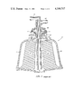
- FIG. 6 is a cross-sectional elevational view of a blood-processing centrifuge bowl incorporating an improved rotary seal according to this invention
- FIG. 7 is a plan view of the centrifuge bowl of FIG. 6;
- FIG. 8 is a partial cross-sectional elevational view of one alternative embodiment of the improved rotary seal according to this invention.
- FIG. 9 is a partial cross-sectional view of another alternative embodiment of the improved rotary seal according to this invention.
- FIG. 10 is a cross-sectional view along line 10--10 in FIG. 9.
- FIG. 1 illustrates a blood-processing centrifuge 10 incorporating a rotary centrifuge seal of a type typically used in the prior art.
- blood-processing centrifuge 10 has a centrifuge bowl 12 which rotates around a cylindrical core section 14 during operation to separate blood into its components.
- Whole blood is introduced into the central port 16 located at the bottom of centrifuge 10 through feed tube 18 which extends upwardly through the center of centrifuge 10 and then makes a 90° turn at its upper end to form inlet port 19 which can be connected to blood tubing (not shown).
- Feed tube 18 remains stationary during operation of centrifuge 10 whereas bowl 12 spins at high speed.
- Peripheral port 20 is provided to allow separated blood components to flow out of centrifuge 10. Separated components are transported to peripheral port 20 through a channel formed between upper channel-defining member 22 and lower channel-defining member 24, both of which are attached to feed tube 18.
- a rotary seal is formed from rotatable ceramic ring 26 attached by adapter rings 27 and 27' which in turn are attached to centrifuge bowl 12.
- the upper surface of ceramic rotatable ring 26 is smooth and provides a sealing surface with a similar smooth and sealing surface on the bottom of ring 28. Therefore, contact between these respective surfaces forms a dynamic seal between rotatable and stationary elements of blood-processing centrifuge 10.
- a secondary seal is formed from elastomeric diaphragm 30, which is locked into a keyhole slot in feed tube 18 at one end and indirectly fixed to carbon ring 28 by an adhesive joint to adapter ring 29 at its other end.
- FIG. 2 One serious problem encountered with a rotary centrifuge seal of the type illustrated in FIG. 1 is illustrated in FIG. 2.
- solid particles generated at contact areas between rotatable ceramic ring 26 and fixed graphite ring 28 during operation of centrifuge 10 can fly away from the dynamic seal.
- such particles can be projected in many directions and some of these particles can eventually find their way into blood components that have been processed.
- FIG. 3 Two ring members of an improved rotary seal according to this invention are shown in FIG. 3.
- a rotatable ring member 40 is employed, as well as a non-rotatable ring member 42, and there is an area of contact 44 between rings 40 and 42.
- the term "non-rotatable” is used in conjunction with ring member 42 in preference to the term “fixed” because, although ring member 42 does remain stationary in normal operation, it is possible in certain embodiments for it to rotate slightly under certain exceptional circumstances prior to attaining a stationary position, as is described below, particularly with reference to FIGS. 9 and 10.
- Non-rotatable ring member 42 has, however, been modified to provide increased protection against contamination of blood components with particulate matter generated by the rotary seal. This is achieved by providing an area of non-contact 46 which is located radially inwardly from the area of contact 44. This area of non-contact 46 can be formed by making a continuous recessed portion in the sealing face of ring 42 which is adjacent to the area of contact 44. A typical clearance between the sealing faces of ring members 40 and 42 at the area of non-contact 46 is 0.005 inches.
- the area of non-contact 46 serves as a means for entrapping solid particles generated in the area of contact 44.
- One particle is shown for illustration, and this particle is first deflected by the recessed portion in the sealing surface of ring 42 and eventually settles upon the surface of rotatable ring member 40. Since ring member 40 is rotating at high speed during operation of the centrifuge, rotational velocity is imparted to the particle resting on its surface which causes the particle to be centrifugally conveyed back to the area of contact 44.
- the surface of this recessed area is joined to the seal contact area by a section of conical surface 48 which slopes gradually toward the contact surface thus providing easy entry of particles into the region of contact 44.
- the particle is then ingested in the area of contact 44 and ground to fine particles which are expelled at the outer surface of the dynamic seal where they cannot find their way into blood components which are being processed.
- FIG. 5 illustrates an alternative embodiment of an improved rotary centrifuge seal according to this invention.
- the seal has a rotatable lower ring 40. It also has a non-rotatable ring 50 which has another configuration adjacent to its sealing surface to entrap particles and redirect them back to the area of contact between the ring members.
- a series of decreasingly shallower recessed portions 52, 54 and 56 serve a similar purpose to the single recessed portion shown in FIG. 3.
- FIG. 6 illustrates a blood-processing centrifuge 60 similar but not identical to that of FIG. 1. Similar elements have been given similar numerals for purposes of convenience. Modified centrifuge 60 shown in FIG. 6 operates in a similar manner to centrifuge 10 shown in FIG. 1, except that it has an improved design to minimize particle generation and to entrap and redirect any particles which are generated.
- Centrifuge 60 contains an improved rotary seal of the type illustrated in FIGS. 3 and 4. In operation, this rotary seal prevents escape of sterilized gas, such as air, CO 2 , etc., contained within the closed system and also prevents contamination of the sterilized gas by the external atmosphere.
- sterilized gas such as air, CO 2 , etc.
- This improved seal serves to entrap any particles on the blood pathway side generated between the sealing surfaces of lower ceramic rotatable ring 40 and upper non-rotatable graphite ring 42. As discussed above, any particles generated settle upon the shoulder of ring 40 and are then centrifugally conveyed towards the area of contact 44 between rings 40 and 42 where they are ingested, ground to extremely fine particles, and expelled outwardly from the seal so that they do not become entrained in blood being processed.
- the rotary seal shown has several additional improvements.
- One of these is an internal rotating shield 66 which is attached to the inside wall of rotatable ring 40.
- Shield 66 can be formed from a variety of materials, but a material such as aluminum is preferred because of its light weight and corrosion-resistance properties. Shield 66 adds one more means for preventing solid particles which may be generated from entering blood components being processed.
- Resilient diaphragm 68 which can be formed from an elastomeric material, has a lock configuration 70 at its upper end which fits snugly into a keyhole positioned in the upper section of upper channel-defining member 62. Its lower end 72 is designed so that it has to be stretched before it can be slipped over the vertical support 73 on ring member 42; therefore, no adhesive is usually necessary to hold diaphragm 68 over support 73. Adhesives can be used but are usually undesirable since they may run out from the areas in which they are applied thereby providing another possible contaminant within the centrifuge.
- the shape and positioning of the respective elements forming the effluent channel for blood components is also improved in centrifuge 60.
- the improved rotary seal is positioned a considerable distance away from blood component effluent channel by means of verticle bowl section 74 and inclined bowl section 76. This provides sufficient distance between exiting blood components and the seal rings so that any heat generated at the seal rings will not be in close thermal contact with the blood components.
- Space 78 provides additional thermal insulation between exiting blood components and the rotary seal.
- Both upper and lower channel-defining members 62 and 64 also have an extended diameter.
- the extended diameter serves to reduce the possibility that blood flowing into central port 16 will flow between inlet tube 18 and cylindrical core 14 thereby by-passing the separation zone in centrifuge 60.
- the extended diameter chanel-defining members also provide more heat dissipation area in the area of the rotary seal.
- Upper channel-defining member 62 is secured at its top end by a slip fit into vertical section 81 of the upper portion of the centrifuge structure.
- Lower channel-defining member 62 is integrally attached to the upper portion of inlet tube 18, and inlet tube 18 can be joined by an ultrasonic weld to the inner wall of inlet port 19. The proper distance between members 62 and 64 is maintained by protuberances 65.
- Centrifuge 60 is also provided with an external non-rotatable shield 80 which is part of an integral tube section 81.
- Shield 80 serves to protect the rotary seal from any blows, accidental or deliberate. Such a blow could open the seal thereby destroying the sterility of the system.
- air circulation ports 82 in shield 80 and small vanes 83 on rotating bowl 12 are provided, as illustrated. Vanes 83 can be seen more clearly in FIG. 7 and are appropriately sized to obtain good air circulation through the rotary seal without the concomittant disadvantage of creating excessive noise as bowl 12 rotates at high speed.
- FIG. 8 illustrates an alternative embodiment of the improved rotary seal shown in a centrifuge similar to that of FIG. 6. Elements which are the same have been numbered consistently with elements of FIG. 6.
- Rotatable ring member 90 has a more complex shape than in previous embodiments, and includes a horizontally positioned ring portion 92, a steeply downwardly extending portion 94, a less steeply downwardly extending portion 96, and finally a verticle portion 98. Verticle portion 98 can be bonded to a mating surface 100 provided at the top of centrifuge bowl 12.
- the dynamic seal in this embodiment is formed at the area of contact 44 between the bottom sealing surface of non-rotatable graphite ring 42 and the upper sealing surface of the horizontal ring portion of ring member 90, which is similar to the seal formed by previous embodiments.
- Ring member 90 can be formed from a good heat-conducting material, such as a metal, and thus can serve to conduct heat generated in operation away from the area of contact between ring members 42 and 90 to the extended surface areas of ring member 90 where such heat can be dissipated to air currents created as the centrifuge rotates. This prevents the build-up of heat which could result in a temperature rise with concomitant damage to blood components. Because of the excellent heat dissipation obtained through conduction along ring member 90 and subsequent convection to air currents, outer shield 102 need not be provided with air ports for cooling.
- portion 96 of ring member 90 is resting upon upper channel defining member 62. This is the position of these elements when centrifuge 60 stands alone. However, when centrifuge 60 is locked into a chuck of permanent blood-processing apparatus, stationary components of centrifuge 60 are depressed resulting in a separation of member 62 from portion 96.
- the improved seal of this invention operates with unusual freedom from noise. This is at least partly due to the fact that the normal torque required to overcome the frictional resistance between the non-rotatable and rotatable ring members is transmitted through the elastomeric diaphragm which forms a secondary seal without any direct physical contact between the non-rotatable ring member and any of the other hard components of the assembly.
- the breakaway torque can be greater than the torque capacity of elastomeric diaphragm 68.
- An example of such exceptional circumstances would be the flooding of the seal with blood followed by a period of non-use sufficient to allow the blood to congeal or form a bond between the non-rotatable and rotatable ring members.
- This potential problem can be overcome by providing slight modifications to the seal to enable it to momentarily produce the breakaway torque required at start-up without destruction of the seal.
- non-rotatable ring element 110 is provided with three equidistant tabs 112, 114, 116 on its outer periphery. Tabs 112, 114 and 116 extend into complementary recessed areas 118, 120 and 122, respectively, located on the inner surface of outer shield 124. In normal operation, tabs 112, 114 and 116 do not contact shield 124, which avoids wear and the generation of undesirable noise caused by contact between hard components.
- non-rotatable ring member 110 can rotate just slightly so that tabs 112, 114 and 116 contact the forward edge of recessions 118, 120 and 122, respectively. After such contact is established, torque builds up rapidly until breakaway occurs, after which non-rotatable ring member 110 is returned by the elastic return action of diaphragm 68 to a position where tabs 112, 114 and 116 are once again free floating within their respective recessed portions 118, 120 and 122.
- a significant advantage of the improved rotary seal of this invention is the extremely quiet operation which can be achieved. There are several reasons for this, and some of these can be illustrated with reference to FIGS. 8, 9 and 10. As can be seen in FIG. 8, resilient diaphragm 68 terminates in a flange 72 which extends beyond the edge of non-rotatable ring member 42. Thus, if misalignment between rotating and non-rotating parts in the centrifuge occurs, contact is made only between flange 72 and stationary shield 102. Since flange 72 is formed from resilient material, such as an elastomer, there is no significant noise generated by such contact.
- This invention has industrial applicability in clinical laboratories, blood banks, etc., in the separation of blood into two or more components.
Abstract
Description
Claims (17)
Priority Applications (1)
| Application Number | Priority Date | Filing Date | Title |
|---|---|---|---|
| US06/201,336 US4300717A (en) | 1979-04-02 | 1980-10-27 | Rotary centrifuge seal |
Applications Claiming Priority (2)
| Application Number | Priority Date | Filing Date | Title |
|---|---|---|---|
| US2629279A | 1979-04-02 | 1979-04-02 | |
| US06/201,336 US4300717A (en) | 1979-04-02 | 1980-10-27 | Rotary centrifuge seal |
Related Parent Applications (1)
| Application Number | Title | Priority Date | Filing Date |
|---|---|---|---|
| US2629279A Continuation | 1978-07-17 | 1979-04-02 |
Publications (1)
| Publication Number | Publication Date |
|---|---|
| US4300717A true US4300717A (en) | 1981-11-17 |
Family
ID=26701050
Family Applications (1)
| Application Number | Title | Priority Date | Filing Date |
|---|---|---|---|
| US06/201,336 Expired - Lifetime US4300717A (en) | 1979-04-02 | 1980-10-27 | Rotary centrifuge seal |
Country Status (1)
| Country | Link |
|---|---|
| US (1) | US4300717A (en) |
Cited By (116)
| Publication number | Priority date | Publication date | Assignee | Title |
|---|---|---|---|---|
| US4629564A (en) * | 1984-03-01 | 1986-12-16 | Alfa-Laval Separation Ab | Centrifugal separator with annular sealing means arranged around the rotor outlet for separated liquid |
| FR2588489A1 (en) * | 1985-10-11 | 1987-04-17 | Cardivascular Systems | CENTRIFUGE |
| US4684361A (en) * | 1985-10-11 | 1987-08-04 | Cardiovascular Systems, Inc. | Centrifuge |
| US4692136A (en) * | 1985-10-11 | 1987-09-08 | Cardiovascular Systems Inc. | Centrifuge |
| US4718888A (en) * | 1986-03-10 | 1988-01-12 | Cardiovascular Systems, Inc. | Centrifuge bowl mount |
| EP0257755A1 (en) * | 1986-07-22 | 1988-03-02 | Haemonetics Corporation | Centrifuge bowl or rotor for plasmapheresis |
| US4759744A (en) * | 1986-03-12 | 1988-07-26 | Alfa-Laval Separation Ab | Centrifugal separator with recirculation of separated sludge |
| US4767396A (en) * | 1987-03-03 | 1988-08-30 | Haemonetics Corporation | Method and apparatus for processing biological fluids |
| US4795419A (en) * | 1985-10-11 | 1989-01-03 | Kardiothor, Inc. | Centrifuge |
| WO1989001792A1 (en) * | 1987-08-28 | 1989-03-09 | Haemonetics Corporation | Method and apparatus for cell washing |
| US4859333A (en) * | 1987-04-07 | 1989-08-22 | Dideco S.P.A. | Continous blood centrifugation cell |
| US4879031A (en) * | 1987-04-07 | 1989-11-07 | Dideco S.P.A. | Blood centrifugation cell |
| US4921473A (en) * | 1989-02-02 | 1990-05-01 | Therakos, Inc. | Multicomponent fluid separation and irradiation system |
| US4943273A (en) * | 1986-07-22 | 1990-07-24 | Haemonetics Corporation | Disposable centrifuge bowl for blood processing |
| US4983158A (en) * | 1986-07-22 | 1991-01-08 | Haemonetics Corporation | Plasmapheresis centrifuge bowl |
| US5045048A (en) * | 1990-03-29 | 1991-09-03 | Haemonetics Corporation | Rotary centrifuge bowl and seal for blood processing |
| US5092995A (en) * | 1987-11-28 | 1992-03-03 | Heinkel Industriezentrifugen Gmbh & Co. | Invertible filter centrifuge with a filler pipe connectable to a pressurization or depressurization source |
| US5100372A (en) * | 1990-03-02 | 1992-03-31 | Haemonetics Corporation | Core for blood processing apparatus |
| US5312319A (en) * | 1992-04-29 | 1994-05-17 | Cobe Laboratories, Inc. | Centrifuge having a single swing arm for retaining a stator tube |
| EP0608519A2 (en) * | 1993-01-29 | 1994-08-03 | Elp Rochat | Centrifugal separator |
| EP0619145A2 (en) * | 1993-04-05 | 1994-10-12 | Electromedics, Inc. | Rotary seal for centrifuge |
| US5405308A (en) * | 1992-10-13 | 1995-04-11 | Haemonetics Corporation | Disposable centrifuge rotor and core for blood processing |
| US5462716A (en) * | 1991-11-11 | 1995-10-31 | Holm; Niels E. | Container for receiving and separating a fluid, preferably blood plasma, into its ingredients |
| EP0682953A1 (en) | 1994-05-20 | 1995-11-22 | Haemonetics Corporation | Two-stage blood cell wash process |
| US5480378A (en) * | 1990-05-14 | 1996-01-02 | Weis-Fogh; Ulla | Apparatus for preparing a concentrate of coagulation factors from a blood sample |
| US5514070A (en) * | 1994-01-21 | 1996-05-07 | Haemonetics Corporation | Plural collector centrifuge bowl for blood processing |
| US5585007A (en) * | 1994-12-07 | 1996-12-17 | Plasmaseal Corporation | Plasma concentrate and tissue sealant methods and apparatuses for making concentrated plasma and/or tissue sealant |
| US5603845A (en) * | 1993-11-19 | 1997-02-18 | E. R. Squibb & Sons, Inc. | Liquid separation apparatus and method |
| US5618919A (en) * | 1986-11-10 | 1997-04-08 | Biopure Corportion | Ultra pure hemoglobin solutions and blood-substitutes |
| US5728060A (en) * | 1995-06-07 | 1998-03-17 | Transfusion Technologies Corporation | Blood collection and separation system |
| US5733446A (en) * | 1994-12-02 | 1998-03-31 | Bristol-Myers Squibb Company | Centrifuge with annular filter |
| US5733253A (en) * | 1994-10-13 | 1998-03-31 | Transfusion Technologies Corporation | Fluid separation system |
| US5738784A (en) * | 1994-12-02 | 1998-04-14 | E.R. Squibb & Sons, Inc. | Device for separating a blood component from blood or plasma |
| WO1998030304A1 (en) * | 1997-01-08 | 1998-07-16 | Bristol-Myers Squibb Company | A centrifuge apparatus with temperature control means |
| US5830352A (en) * | 1994-12-02 | 1998-11-03 | Bristol-Myers Squibb Company | Centrifuge reagent delivery system |
| WO1998052629A2 (en) * | 1997-05-20 | 1998-11-26 | Zymequest, Inc. | Cell processing systems |
| US5919125A (en) * | 1997-07-11 | 1999-07-06 | Cobe Laboratories, Inc. | Centrifuge bowl for autologous blood salvage |
| US5976388A (en) * | 1997-05-20 | 1999-11-02 | Cobe Cardiovascular Operating Co., Inc. | Method and apparatus for autologous blood salvage |
| EP0987037A2 (en) * | 1997-05-20 | 2000-03-22 | Zymequest, Inc. | Rotating seals for cell processing systems |
| US6132598A (en) * | 1997-01-08 | 2000-10-17 | Bristol-Myers Squibb Company | Centrifuge apparatus with temperature control means |
| US6296602B1 (en) | 1999-03-17 | 2001-10-02 | Transfusion Technologies Corporation | Method for collecting platelets and other blood components from whole blood |
| US6464624B2 (en) * | 1999-06-03 | 2002-10-15 | Haemonetics Corporation | Blood processing method and apparatus using a centrifugation bowl with filter core |
| US6589155B2 (en) | 2001-04-09 | 2003-07-08 | Medtronic, Inc. | Miniaturized blood centrifuge having side mounted motor with belt drive |
| US6589153B2 (en) | 2001-09-24 | 2003-07-08 | Medtronic, Inc. | Blood centrifuge with exterior mounted, self-balancing collection chambers |
| US6605028B2 (en) | 2001-04-09 | 2003-08-12 | Medtronic, Inc. | Blood centrifuge having integral heating to control cellular component temperature |
| US6612975B2 (en) | 2001-04-09 | 2003-09-02 | Medtronic, Inc. | Blood centrifuge with an enhanced internal drive assembly |
| US20030181305A1 (en) * | 2002-03-04 | 2003-09-25 | Briggs Dennis A. | Method and apparatus for the continuous separation of biological fluids into components |
| US6629919B2 (en) * | 1999-06-03 | 2003-10-07 | Haemonetics Corporation | Core for blood processing apparatus |
| US6632191B1 (en) | 1994-10-13 | 2003-10-14 | Haemonetics Corporation | System and method for separating blood components |
| US20040009862A1 (en) * | 2001-04-09 | 2004-01-15 | Dolecek Victor D. | System for automated separation of fluid components |
| US20040055937A1 (en) * | 2001-04-09 | 2004-03-25 | Dolecek Victor D. | Blood centrifuge having overhanging disposable blood container |
| US20040147865A1 (en) * | 1994-10-13 | 2004-07-29 | Cianci James P. | System and method for processing blood |
| US20050009680A1 (en) * | 1997-05-20 | 2005-01-13 | Victor Sacco | Apparatus for method for expressing fluid materials |
| US20060199720A1 (en) * | 2005-01-21 | 2006-09-07 | Tien-Chu Juan | Plasmapheresis centrifuge bowl |
| US7211037B2 (en) | 2002-03-04 | 2007-05-01 | Therakos, Inc. | Apparatus for the continuous separation of biological fluids into components and method of using same |
| US20070213191A1 (en) * | 2006-03-07 | 2007-09-13 | Jacques Chammas | Rotor defining a fluid separation chamber of varying volume |
| WO2008006237A1 (en) * | 2006-06-13 | 2008-01-17 | Xiaojin Wang | Centrifugal cup consisting of multiple relatively independent separation chambe |
| US7347948B2 (en) | 2001-04-09 | 2008-03-25 | Ateriocyte Medical Systems, Inc. | Blood centrifuge having clamshell blood reservoir holder with index line |
| US7374678B2 (en) | 2002-05-24 | 2008-05-20 | Biomet Biologics, Inc. | Apparatus and method for separating and concentrating fluids containing multiple components |
| US20080132397A1 (en) * | 2005-01-25 | 2008-06-05 | Jean-Denis Rochat | Centrifugal Separator For a Physiological Fluid, Particularly Blood |
| US20080128367A1 (en) * | 2005-02-03 | 2008-06-05 | Jean-Denis Rochat | Method and Disposable Device For Blood Centrifugal Separation |
| US20080153686A1 (en) * | 2005-01-25 | 2008-06-26 | Jean-Denis Rochat | Disposable Device for the Continuous Centrifugal Separation of a Physiological Fluid |
| US7470371B2 (en) | 2002-05-03 | 2008-12-30 | Hanuman Llc | Methods and apparatus for isolating platelets from blood |
| US7476209B2 (en) | 2004-12-21 | 2009-01-13 | Therakos, Inc. | Method and apparatus for collecting a blood component and performing a photopheresis treatment |
| US7479123B2 (en) | 2002-03-04 | 2009-01-20 | Therakos, Inc. | Method for collecting a desired blood component and performing a photopheresis treatment |
| CN100551545C (en) * | 2004-12-07 | 2009-10-21 | 北京恒中科技有限公司 | A kind of Centrifuge Cup that constitutes by a plurality of relatively independent separation chambers |
| WO2009131659A1 (en) * | 2008-04-22 | 2009-10-29 | Boston Technology Consultants Group, Inc. | Single use centrifuge system |
| US7708152B2 (en) | 2005-02-07 | 2010-05-04 | Hanuman Llc | Method and apparatus for preparing platelet rich plasma and concentrates thereof |
| US7780860B2 (en) | 2002-05-24 | 2010-08-24 | Biomet Biologics, Llc | Apparatus and method for separating and concentrating fluids containing multiple components |
| US7806276B2 (en) | 2007-04-12 | 2010-10-05 | Hanuman, Llc | Buoy suspension fractionation system |
| US7824559B2 (en) | 2005-02-07 | 2010-11-02 | Hanumann, LLC | Apparatus and method for preparing platelet rich plasma and concentrates thereof |
| US7832566B2 (en) | 2002-05-24 | 2010-11-16 | Biomet Biologics, Llc | Method and apparatus for separating and concentrating a component from a multi-component material including macroparticles |
| US7845499B2 (en) | 2002-05-24 | 2010-12-07 | Biomet Biologics, Llc | Apparatus and method for separating and concentrating fluids containing multiple components |
| US7866485B2 (en) | 2005-02-07 | 2011-01-11 | Hanuman, Llc | Apparatus and method for preparing platelet rich plasma and concentrates thereof |
| US7992725B2 (en) | 2002-05-03 | 2011-08-09 | Biomet Biologics, Llc | Buoy suspension fractionation system |
| US8012077B2 (en) | 2008-05-23 | 2011-09-06 | Biomet Biologics, Llc | Blood separating device |
| WO2012027312A1 (en) | 2010-08-24 | 2012-03-01 | Fenwal, Inc. | Methods and systems for anticoagulating blood |
| US8187475B2 (en) | 2009-03-06 | 2012-05-29 | Biomet Biologics, Llc | Method and apparatus for producing autologous thrombin |
| WO2012071034A1 (en) * | 2010-11-23 | 2012-05-31 | Haemonetics Corporation | Apheresis bowl with improved vibration characteristics |
| US8313954B2 (en) | 2009-04-03 | 2012-11-20 | Biomet Biologics, Llc | All-in-one means of separating blood components |
| US8328024B2 (en) | 2007-04-12 | 2012-12-11 | Hanuman, Llc | Buoy suspension fractionation system |
| US8337711B2 (en) | 2008-02-29 | 2012-12-25 | Biomet Biologics, Llc | System and process for separating a material |
| US8454548B2 (en) | 2008-04-14 | 2013-06-04 | Haemonetics Corporation | System and method for plasma reduced platelet collection |
| US8567609B2 (en) | 2006-05-25 | 2013-10-29 | Biomet Biologics, Llc | Apparatus and method for separating and concentrating fluids containing multiple components |
| US8591391B2 (en) | 2010-04-12 | 2013-11-26 | Biomet Biologics, Llc | Method and apparatus for separating a material |
| US8628489B2 (en) | 2008-04-14 | 2014-01-14 | Haemonetics Corporation | Three-line apheresis system and method |
| US8647289B2 (en) | 2008-04-14 | 2014-02-11 | Haemonetics Corporation | System and method for optimized apheresis draw and return |
| WO2014071365A1 (en) * | 2012-11-05 | 2014-05-08 | Haemonetics Corporation | Continuous flow separation chamber |
| US8808978B2 (en) | 2010-11-05 | 2014-08-19 | Haemonetics Corporation | System and method for automated platelet wash |
| US8834402B2 (en) | 2009-03-12 | 2014-09-16 | Haemonetics Corporation | System and method for the re-anticoagulation of platelet rich plasma |
| US8986238B2 (en) | 2012-08-15 | 2015-03-24 | Cyclone Medtech, Inc. | Systems and methods for salvaging red blood cells for autotransfusion |
| US9011800B2 (en) | 2009-07-16 | 2015-04-21 | Biomet Biologics, Llc | Method and apparatus for separating biological materials |
| KR101530565B1 (en) * | 2013-08-12 | 2015-06-22 | 이현근 | Casing assembly for centrifugal machine |
| US20150284671A1 (en) * | 2008-04-22 | 2015-10-08 | Pneumatic Scale Corporation | Single use centrifuge system for highly concentrated and/or turbid feeds |
| US9302042B2 (en) | 2010-12-30 | 2016-04-05 | Haemonetics Corporation | System and method for collecting platelets and anticipating plasma return |
| CN105664278A (en) * | 2010-11-23 | 2016-06-15 | 美国血液技术公司 | Single-blood sampling liquid constituent drum with improved vibration characteristic |
| US9556243B2 (en) | 2013-03-15 | 2017-01-31 | Biomet Biologies, LLC | Methods for making cytokine compositions from tissues using non-centrifugal methods |
| US9642956B2 (en) | 2012-08-27 | 2017-05-09 | Biomet Biologics, Llc | Apparatus and method for separating and concentrating fluids containing multiple components |
| US9701728B2 (en) | 2008-02-27 | 2017-07-11 | Biomet Biologics, Llc | Methods and compositions for delivering interleukin-1 receptor antagonist |
| US9713810B2 (en) | 2015-03-30 | 2017-07-25 | Biomet Biologics, Llc | Cell washing plunger using centrifugal force |
| US9757721B2 (en) | 2015-05-11 | 2017-09-12 | Biomet Biologics, Llc | Cell washing plunger using centrifugal force |
| US9895418B2 (en) | 2013-03-15 | 2018-02-20 | Biomet Biologics, Llc | Treatment of peripheral vascular disease using protein solutions |
| US9897589B2 (en) | 2002-05-24 | 2018-02-20 | Biomet Biologics, Llc | Apparatus and method for separating and concentrating fluids containing multiple components |
| US9950035B2 (en) | 2013-03-15 | 2018-04-24 | Biomet Biologics, Llc | Methods and non-immunogenic compositions for treating inflammatory disorders |
| US10143725B2 (en) | 2013-03-15 | 2018-12-04 | Biomet Biologics, Llc | Treatment of pain using protein solutions |
| US10384216B1 (en) * | 2008-04-22 | 2019-08-20 | Pneumatic Scale Corporation | Centrifuge system including a control circuit that controls positive back pressure within the centrifuge core |
| US10576130B2 (en) | 2013-03-15 | 2020-03-03 | Biomet Manufacturing, Llc | Treatment of collagen defects using protein solutions |
| US10683478B1 (en) * | 2019-05-16 | 2020-06-16 | Shenzhen Eureka biotechnology Co. Ltd | Device and system for processing a liquid sample containing cells |
| US10758652B2 (en) | 2017-05-30 | 2020-09-01 | Haemonetics Corporation | System and method for collecting plasma |
| US10792416B2 (en) | 2017-05-30 | 2020-10-06 | Haemonetics Corporation | System and method for collecting plasma |
| US10946131B2 (en) | 2018-05-21 | 2021-03-16 | Fenwal, Inc. | Systems and methods for optimization of plasma collection volumes |
| US20210205734A1 (en) * | 2019-06-06 | 2021-07-08 | Pneumatic Scale Corporation | Centrifuge System for Separating Cells in Suspension |
| US11065376B2 (en) | 2018-03-26 | 2021-07-20 | Haemonetics Corporation | Plasmapheresis centrifuge bowl |
| US11412967B2 (en) | 2018-05-21 | 2022-08-16 | Fenwal, Inc. | Systems and methods for plasma collection |
| US11837357B2 (en) | 2011-05-18 | 2023-12-05 | Fenwal, Inc. | Plasma collection with remote programming |
| US11957733B2 (en) | 2019-10-28 | 2024-04-16 | Biomet Manufacturing, Llc | Treatment of collagen defects using protein solutions |
Citations (10)
| Publication number | Priority date | Publication date | Assignee | Title |
|---|---|---|---|---|
| US2005094A (en) * | 1932-01-25 | 1935-06-18 | Laval Separator Co De | Centrifugal separator |
| US2673748A (en) * | 1949-01-19 | 1954-03-30 | Perfecting Service Company | Rotary connection |
| DE908692C (en) * | 1941-12-04 | 1954-04-08 | Fritz Oesterlen Dr Ing | Side channel gap seal |
| US2858149A (en) * | 1954-03-23 | 1958-10-28 | City Nat Bank And Trust Compan | Rotary seal |
| US2878992A (en) * | 1956-12-28 | 1959-03-24 | Beckman Instruments Inc | Centrifuge apparatus and rotor therefor |
| US3409213A (en) * | 1967-01-23 | 1968-11-05 | 500 Inc | Rotary seal and centrifuge incorporation |
| US3565330A (en) * | 1968-07-11 | 1971-02-23 | Cryogenic Technology Inc | Rotary seal and centrifuge incorporating same |
| US3652183A (en) * | 1970-10-15 | 1972-03-28 | John E Pottharst Jr | Compressor |
| US3770181A (en) * | 1970-12-30 | 1973-11-06 | Stenberg Flygt Ab | Sealing ring for slide-ring seals |
| US3801142A (en) * | 1972-06-30 | 1974-04-02 | Ibm | Fluid coupling |
-
1980
- 1980-10-27 US US06/201,336 patent/US4300717A/en not_active Expired - Lifetime
Patent Citations (10)
| Publication number | Priority date | Publication date | Assignee | Title |
|---|---|---|---|---|
| US2005094A (en) * | 1932-01-25 | 1935-06-18 | Laval Separator Co De | Centrifugal separator |
| DE908692C (en) * | 1941-12-04 | 1954-04-08 | Fritz Oesterlen Dr Ing | Side channel gap seal |
| US2673748A (en) * | 1949-01-19 | 1954-03-30 | Perfecting Service Company | Rotary connection |
| US2858149A (en) * | 1954-03-23 | 1958-10-28 | City Nat Bank And Trust Compan | Rotary seal |
| US2878992A (en) * | 1956-12-28 | 1959-03-24 | Beckman Instruments Inc | Centrifuge apparatus and rotor therefor |
| US3409213A (en) * | 1967-01-23 | 1968-11-05 | 500 Inc | Rotary seal and centrifuge incorporation |
| US3565330A (en) * | 1968-07-11 | 1971-02-23 | Cryogenic Technology Inc | Rotary seal and centrifuge incorporating same |
| US3652183A (en) * | 1970-10-15 | 1972-03-28 | John E Pottharst Jr | Compressor |
| US3770181A (en) * | 1970-12-30 | 1973-11-06 | Stenberg Flygt Ab | Sealing ring for slide-ring seals |
| US3801142A (en) * | 1972-06-30 | 1974-04-02 | Ibm | Fluid coupling |
Cited By (237)
| Publication number | Priority date | Publication date | Assignee | Title |
|---|---|---|---|---|
| US4629564A (en) * | 1984-03-01 | 1986-12-16 | Alfa-Laval Separation Ab | Centrifugal separator with annular sealing means arranged around the rotor outlet for separated liquid |
| US4795419A (en) * | 1985-10-11 | 1989-01-03 | Kardiothor, Inc. | Centrifuge |
| FR2588489A1 (en) * | 1985-10-11 | 1987-04-17 | Cardivascular Systems | CENTRIFUGE |
| US4684361A (en) * | 1985-10-11 | 1987-08-04 | Cardiovascular Systems, Inc. | Centrifuge |
| US4692136A (en) * | 1985-10-11 | 1987-09-08 | Cardiovascular Systems Inc. | Centrifuge |
| US4718888A (en) * | 1986-03-10 | 1988-01-12 | Cardiovascular Systems, Inc. | Centrifuge bowl mount |
| US4759744A (en) * | 1986-03-12 | 1988-07-26 | Alfa-Laval Separation Ab | Centrifugal separator with recirculation of separated sludge |
| US4943273A (en) * | 1986-07-22 | 1990-07-24 | Haemonetics Corporation | Disposable centrifuge bowl for blood processing |
| EP0257755A1 (en) * | 1986-07-22 | 1988-03-02 | Haemonetics Corporation | Centrifuge bowl or rotor for plasmapheresis |
| US4983158A (en) * | 1986-07-22 | 1991-01-08 | Haemonetics Corporation | Plasmapheresis centrifuge bowl |
| US5618919A (en) * | 1986-11-10 | 1997-04-08 | Biopure Corportion | Ultra pure hemoglobin solutions and blood-substitutes |
| US5905141A (en) * | 1986-11-10 | 1999-05-18 | Biopure Corporation | Ultra pure hemoglobin solutions and blood substitutes |
| US6506725B1 (en) | 1986-11-10 | 2003-01-14 | Biopure Corporation | Ultra pure hemoglobin solutions and blood-substitutes |
| US4767396A (en) * | 1987-03-03 | 1988-08-30 | Haemonetics Corporation | Method and apparatus for processing biological fluids |
| US4859333A (en) * | 1987-04-07 | 1989-08-22 | Dideco S.P.A. | Continous blood centrifugation cell |
| US4879031A (en) * | 1987-04-07 | 1989-11-07 | Dideco S.P.A. | Blood centrifugation cell |
| WO1989001792A1 (en) * | 1987-08-28 | 1989-03-09 | Haemonetics Corporation | Method and apparatus for cell washing |
| US5092995A (en) * | 1987-11-28 | 1992-03-03 | Heinkel Industriezentrifugen Gmbh & Co. | Invertible filter centrifuge with a filler pipe connectable to a pressurization or depressurization source |
| US4921473A (en) * | 1989-02-02 | 1990-05-01 | Therakos, Inc. | Multicomponent fluid separation and irradiation system |
| US5100372A (en) * | 1990-03-02 | 1992-03-31 | Haemonetics Corporation | Core for blood processing apparatus |
| US5045048A (en) * | 1990-03-29 | 1991-09-03 | Haemonetics Corporation | Rotary centrifuge bowl and seal for blood processing |
| US5480378A (en) * | 1990-05-14 | 1996-01-02 | Weis-Fogh; Ulla | Apparatus for preparing a concentrate of coagulation factors from a blood sample |
| US5658533A (en) * | 1991-11-11 | 1997-08-19 | E.R. Squibb & Sons, Inc. | Container for receiving and separating a fluid into its ingredients |
| US5746979A (en) * | 1991-11-11 | 1998-05-05 | F. R, Squibb & Sons, Inc. | Method for receiving and separating a fluid into its ingredients |
| US5674458A (en) * | 1991-11-11 | 1997-10-07 | E. R. Squibb & Sons, Inc. | Container for receiving and separating a fluid into its ingredients |
| US5462716A (en) * | 1991-11-11 | 1995-10-31 | Holm; Niels E. | Container for receiving and separating a fluid, preferably blood plasma, into its ingredients |
| US5312319A (en) * | 1992-04-29 | 1994-05-17 | Cobe Laboratories, Inc. | Centrifuge having a single swing arm for retaining a stator tube |
| US5405308A (en) * | 1992-10-13 | 1995-04-11 | Haemonetics Corporation | Disposable centrifuge rotor and core for blood processing |
| US5387174A (en) * | 1993-01-29 | 1995-02-07 | Elp Rochat | Centrifugal separator with disposable bowl assembly |
| EP0608519A3 (en) * | 1993-01-29 | 1995-01-04 | Elp Rochat | Centrifugal separator. |
| EP0608519A2 (en) * | 1993-01-29 | 1994-08-03 | Elp Rochat | Centrifugal separator |
| EP0619145A2 (en) * | 1993-04-05 | 1994-10-12 | Electromedics, Inc. | Rotary seal for centrifuge |
| EP0619145A3 (en) * | 1993-04-05 | 1995-04-05 | Electromedics Inc | Rotary seal for centrifuge. |
| US5603845A (en) * | 1993-11-19 | 1997-02-18 | E. R. Squibb & Sons, Inc. | Liquid separation apparatus and method |
| US5858253A (en) * | 1993-11-19 | 1999-01-12 | Bristol-Myers Squibb Company | Blood separation process |
| US5792344A (en) * | 1993-11-19 | 1998-08-11 | Bristol-Myers Squibb Company | Liquid separation container for a centrifugal separator |
| US5741428A (en) * | 1993-11-19 | 1998-04-21 | E.R. Squibb & Sons, Inc. | Rapid centrifugal process for preparing fibrin monomer solution |
| US5776336A (en) * | 1993-11-19 | 1998-07-07 | Bristol-Myers Squibb Company | Annular filter assembly |
| US5514070A (en) * | 1994-01-21 | 1996-05-07 | Haemonetics Corporation | Plural collector centrifuge bowl for blood processing |
| EP0682953A1 (en) | 1994-05-20 | 1995-11-22 | Haemonetics Corporation | Two-stage blood cell wash process |
| US7452322B2 (en) | 1994-10-13 | 2008-11-18 | Haemonetics Corporation | Rotor with elastic diaphragm for liquid-separation system |
| US7332125B2 (en) | 1994-10-13 | 2008-02-19 | Haemonetics Corporation | System and method for processing blood |
| US20030125182A1 (en) * | 1994-10-13 | 2003-07-03 | Headley Thomas D. | Rotor with elastic diaphragm for liquid-separation system |
| US6602179B1 (en) * | 1994-10-13 | 2003-08-05 | Haemonetics Corporation | Rotor with elastic diaphragm defining a liquid separating chamber of varying volume |
| US6379322B1 (en) | 1994-10-13 | 2002-04-30 | Transfusion Technologies Corporation | Blood collection and separation system |
| US6632191B1 (en) | 1994-10-13 | 2003-10-14 | Haemonetics Corporation | System and method for separating blood components |
| US6074335A (en) * | 1994-10-13 | 2000-06-13 | Transfusion Technologies Corporation | Rotor with elastic diaphragm defining a liquid separating chamber of varying volume |
| US6039711A (en) * | 1994-10-13 | 2000-03-21 | Transfusion Technologies Corporation | System for liquid separation |
| US5733253A (en) * | 1994-10-13 | 1998-03-31 | Transfusion Technologies Corporation | Fluid separation system |
| US6019742A (en) * | 1994-10-13 | 2000-02-01 | Transfusion Technologies Corporation | Method for liquid separation |
| US20040147865A1 (en) * | 1994-10-13 | 2004-07-29 | Cianci James P. | System and method for processing blood |
| US5885239A (en) * | 1994-10-13 | 1999-03-23 | Transfusion Technologies Corporation | Method for collecting red blood cells |
| US5958253A (en) * | 1994-12-02 | 1999-09-28 | Bristol-Myers Squibb Company | Centrifuge reagent delivery method |
| US5795489A (en) * | 1994-12-02 | 1998-08-18 | Bristol-Myers Squibb Company | Centrifugal filtration method |
| US5935432A (en) * | 1994-12-02 | 1999-08-10 | Bristol-Myers Squibb Company | Centrifuge reagent delivery system |
| US5738784A (en) * | 1994-12-02 | 1998-04-14 | E.R. Squibb & Sons, Inc. | Device for separating a blood component from blood or plasma |
| US5824230A (en) * | 1994-12-02 | 1998-10-20 | E.R. Squibb & Sons, Inc. | Method and device for separating a component such as fibrin I from blood plasma |
| US5830352A (en) * | 1994-12-02 | 1998-11-03 | Bristol-Myers Squibb Company | Centrifuge reagent delivery system |
| US5733446A (en) * | 1994-12-02 | 1998-03-31 | Bristol-Myers Squibb Company | Centrifuge with annular filter |
| US6214338B1 (en) | 1994-12-07 | 2001-04-10 | Plasmaseal Llc | Plasma concentrate and method of processing blood for same |
| US5585007A (en) * | 1994-12-07 | 1996-12-17 | Plasmaseal Corporation | Plasma concentrate and tissue sealant methods and apparatuses for making concentrated plasma and/or tissue sealant |
| US5788662A (en) * | 1994-12-07 | 1998-08-04 | Plasmaseal Llc | Methods for making concentrated plasma and/or tissue sealant |
| US6007509A (en) * | 1995-06-07 | 1999-12-28 | Transfusion Technologies Corp. | Blood collection and separation system |
| US6641552B1 (en) | 1995-06-07 | 2003-11-04 | Haemonetics Corporation | Blood collection and separation system |
| US5728060A (en) * | 1995-06-07 | 1998-03-17 | Transfusion Technologies Corporation | Blood collection and separation system |
| US6102883A (en) * | 1995-06-07 | 2000-08-15 | Transfusion Technologies Corporation | Blood collection and separation process |
| US5779660A (en) * | 1995-06-07 | 1998-07-14 | Transfusion Technologies Corporation | Blood collection and separation process |
| US6132598A (en) * | 1997-01-08 | 2000-10-17 | Bristol-Myers Squibb Company | Centrifuge apparatus with temperature control means |
| WO1998030304A1 (en) * | 1997-01-08 | 1998-07-16 | Bristol-Myers Squibb Company | A centrifuge apparatus with temperature control means |
| EP0987037A3 (en) * | 1997-05-20 | 2002-07-24 | Zymequest, Inc. | Rotating seals for cell processing systems |
| WO1998052629A2 (en) * | 1997-05-20 | 1998-11-26 | Zymequest, Inc. | Cell processing systems |
| US20050009680A1 (en) * | 1997-05-20 | 2005-01-13 | Victor Sacco | Apparatus for method for expressing fluid materials |
| US20090309308A1 (en) * | 1997-05-20 | 2009-12-17 | Zymequest, Inc. | Rotating seals for cell processing systems |
| US6439577B2 (en) * | 1997-05-20 | 2002-08-27 | Zymequest, Inc. | Rotating seals for cell processing systems |
| US7594663B2 (en) | 1997-05-20 | 2009-09-29 | Zymequest, Inc. | Rotating seals for cell processing systems |
| US20020185820A1 (en) * | 1997-05-20 | 2002-12-12 | Glen Jorgensen | Rotating seals for cell processing systems |
| WO1998052629A3 (en) * | 1997-05-20 | 1999-02-25 | Zymequest Inc | Cell processing systems |
| US7425192B2 (en) | 1997-05-20 | 2008-09-16 | Zymequest, Inc. | Apparatus for method for expressing fluid materials |
| US6852074B1 (en) | 1997-05-20 | 2005-02-08 | Zymequest, Inc. | Biological processing apparatus for expressing fluid material |
| US5976388A (en) * | 1997-05-20 | 1999-11-02 | Cobe Cardiovascular Operating Co., Inc. | Method and apparatus for autologous blood salvage |
| US20060040818A1 (en) * | 1997-05-20 | 2006-02-23 | Glen Jorgensen | Rotating seals for cell processing systems |
| US20070262531A1 (en) * | 1997-05-20 | 2007-11-15 | Zymequest, Inc. | Rotating seals for cell processing systems |
| EP0987037A2 (en) * | 1997-05-20 | 2000-03-22 | Zymequest, Inc. | Rotating seals for cell processing systems |
| US5919125A (en) * | 1997-07-11 | 1999-07-06 | Cobe Laboratories, Inc. | Centrifuge bowl for autologous blood salvage |
| US6296602B1 (en) | 1999-03-17 | 2001-10-02 | Transfusion Technologies Corporation | Method for collecting platelets and other blood components from whole blood |
| US6558307B2 (en) | 1999-03-17 | 2003-05-06 | Haemonetics Corporation | Method for collecting platelets and other blood components from whole blood |
| US6629919B2 (en) * | 1999-06-03 | 2003-10-07 | Haemonetics Corporation | Core for blood processing apparatus |
| US6464624B2 (en) * | 1999-06-03 | 2002-10-15 | Haemonetics Corporation | Blood processing method and apparatus using a centrifugation bowl with filter core |
| US6951612B2 (en) | 2001-04-09 | 2005-10-04 | Medtronic, Inc. | Blood centrifuge having overhanging disposable blood container |
| US6605028B2 (en) | 2001-04-09 | 2003-08-12 | Medtronic, Inc. | Blood centrifuge having integral heating to control cellular component temperature |
| US6790371B2 (en) | 2001-04-09 | 2004-09-14 | Medtronic, Inc. | System and method for automated separation of blood components |
| US20040055937A1 (en) * | 2001-04-09 | 2004-03-25 | Dolecek Victor D. | Blood centrifuge having overhanging disposable blood container |
| US6589155B2 (en) | 2001-04-09 | 2003-07-08 | Medtronic, Inc. | Miniaturized blood centrifuge having side mounted motor with belt drive |
| US6887371B2 (en) | 2001-04-09 | 2005-05-03 | Medtronic, Inc. | System for automated separation of fluid components |
| US6612975B2 (en) | 2001-04-09 | 2003-09-02 | Medtronic, Inc. | Blood centrifuge with an enhanced internal drive assembly |
| US7347948B2 (en) | 2001-04-09 | 2008-03-25 | Ateriocyte Medical Systems, Inc. | Blood centrifuge having clamshell blood reservoir holder with index line |
| US20040009862A1 (en) * | 2001-04-09 | 2004-01-15 | Dolecek Victor D. | System for automated separation of fluid components |
| US6589153B2 (en) | 2001-09-24 | 2003-07-08 | Medtronic, Inc. | Blood centrifuge with exterior mounted, self-balancing collection chambers |
| US20030181305A1 (en) * | 2002-03-04 | 2003-09-25 | Briggs Dennis A. | Method and apparatus for the continuous separation of biological fluids into components |
| US10556055B2 (en) | 2002-03-04 | 2020-02-11 | Mallinckrodt Hospital Products IP Limited | Method for collecting a desired blood component and performing a photopheresis treatment |
| US7914477B2 (en) | 2002-03-04 | 2011-03-29 | Therakos, Inc. | Apparatus for the continuous separation of biological fluids into components and method of using same |
| US7850634B2 (en) | 2002-03-04 | 2010-12-14 | Therakos, Inc. | Method for collecting a desired blood component and performing a photopheresis treatment |
| US9238097B2 (en) | 2002-03-04 | 2016-01-19 | Therakos, Inc. | Method for collecting a desired blood component and performing a photopheresis treatment |
| US7211037B2 (en) | 2002-03-04 | 2007-05-01 | Therakos, Inc. | Apparatus for the continuous separation of biological fluids into components and method of using same |
| US7186230B2 (en) | 2002-03-04 | 2007-03-06 | Therakos, Inc | Method and apparatus for the continuous separation of biological fluids into components |
| US7503889B2 (en) | 2002-03-04 | 2009-03-17 | Dennis Briggs | Apparatus for the continuous separation of biological fluids into components and method of using same |
| US7479123B2 (en) | 2002-03-04 | 2009-01-20 | Therakos, Inc. | Method for collecting a desired blood component and performing a photopheresis treatment |
| US8950586B2 (en) | 2002-05-03 | 2015-02-10 | Hanuman Llc | Methods and apparatus for isolating platelets from blood |
| US7470371B2 (en) | 2002-05-03 | 2008-12-30 | Hanuman Llc | Methods and apparatus for isolating platelets from blood |
| US8187477B2 (en) | 2002-05-03 | 2012-05-29 | Hanuman, Llc | Methods and apparatus for isolating platelets from blood |
| US7992725B2 (en) | 2002-05-03 | 2011-08-09 | Biomet Biologics, Llc | Buoy suspension fractionation system |
| US7837884B2 (en) | 2002-05-03 | 2010-11-23 | Hanuman, Llc | Methods and apparatus for isolating platelets from blood |
| US9114334B2 (en) | 2002-05-24 | 2015-08-25 | Biomet Biologics, Llc | Apparatus and method for separating and concentrating fluids containing multiple components |
| US8603346B2 (en) | 2002-05-24 | 2013-12-10 | Biomet Biologics, Llc | Apparatus and method for separating and concentrating fluids containing multiple components |
| US9897589B2 (en) | 2002-05-24 | 2018-02-20 | Biomet Biologics, Llc | Apparatus and method for separating and concentrating fluids containing multiple components |
| US8062534B2 (en) | 2002-05-24 | 2011-11-22 | Biomet Biologics, Llc | Apparatus and method for separating and concentrating fluids containing multiple components |
| US7780860B2 (en) | 2002-05-24 | 2010-08-24 | Biomet Biologics, Llc | Apparatus and method for separating and concentrating fluids containing multiple components |
| US8048321B2 (en) | 2002-05-24 | 2011-11-01 | Biomet Biologics, Llc | Apparatus and method for separating and concentrating fluids containing multiple components |
| US8163184B2 (en) | 2002-05-24 | 2012-04-24 | Biomet Biologics, Llc | Apparatus and method for separating and concentrating fluids containing multiple components |
| US7832566B2 (en) | 2002-05-24 | 2010-11-16 | Biomet Biologics, Llc | Method and apparatus for separating and concentrating a component from a multi-component material including macroparticles |
| US10183042B2 (en) | 2002-05-24 | 2019-01-22 | Biomet Manufacturing, Llc | Apparatus and method for separating and concentrating fluids containing multiple components |
| US7845499B2 (en) | 2002-05-24 | 2010-12-07 | Biomet Biologics, Llc | Apparatus and method for separating and concentrating fluids containing multiple components |
| US8808551B2 (en) | 2002-05-24 | 2014-08-19 | Biomet Biologics, Llc | Apparatus and method for separating and concentrating fluids containing multiple components |
| US7374678B2 (en) | 2002-05-24 | 2008-05-20 | Biomet Biologics, Inc. | Apparatus and method for separating and concentrating fluids containing multiple components |
| US10393728B2 (en) | 2002-05-24 | 2019-08-27 | Biomet Biologics, Llc | Apparatus and method for separating and concentrating fluids containing multiple components |
| US7914689B2 (en) | 2002-05-24 | 2011-03-29 | Biomet Biologics, Llc | Apparatus and method for separating and concentrating fluids containing multiple components |
| CN100551545C (en) * | 2004-12-07 | 2009-10-21 | 北京恒中科技有限公司 | A kind of Centrifuge Cup that constitutes by a plurality of relatively independent separation chambers |
| US7476209B2 (en) | 2004-12-21 | 2009-01-13 | Therakos, Inc. | Method and apparatus for collecting a blood component and performing a photopheresis treatment |
| US20060199720A1 (en) * | 2005-01-21 | 2006-09-07 | Tien-Chu Juan | Plasmapheresis centrifuge bowl |
| US20080132397A1 (en) * | 2005-01-25 | 2008-06-05 | Jean-Denis Rochat | Centrifugal Separator For a Physiological Fluid, Particularly Blood |
| US8348823B2 (en) | 2005-01-25 | 2013-01-08 | Jean-Denis Rochat | Disposable device for the continuous centrifugal separation of a physiological fluid |
| US20080153686A1 (en) * | 2005-01-25 | 2008-06-26 | Jean-Denis Rochat | Disposable Device for the Continuous Centrifugal Separation of a Physiological Fluid |
| US8070664B2 (en) * | 2005-01-25 | 2011-12-06 | Jean-Denis Rochat | Disposable device for the continuous centrifugal separation of a physiological fluid |
| US20080128367A1 (en) * | 2005-02-03 | 2008-06-05 | Jean-Denis Rochat | Method and Disposable Device For Blood Centrifugal Separation |
| US7824559B2 (en) | 2005-02-07 | 2010-11-02 | Hanumann, LLC | Apparatus and method for preparing platelet rich plasma and concentrates thereof |
| US7866485B2 (en) | 2005-02-07 | 2011-01-11 | Hanuman, Llc | Apparatus and method for preparing platelet rich plasma and concentrates thereof |
| US7987995B2 (en) | 2005-02-07 | 2011-08-02 | Hanuman, Llc | Method and apparatus for preparing platelet rich plasma and concentrates thereof |
| US8133389B2 (en) | 2005-02-07 | 2012-03-13 | Hanuman, Llc | Method and apparatus for preparing platelet rich plasma and concentrates thereof |
| US8096422B2 (en) | 2005-02-07 | 2012-01-17 | Hanuman Llc | Apparatus and method for preparing platelet rich plasma and concentrates thereof |
| US8105495B2 (en) | 2005-02-07 | 2012-01-31 | Hanuman, Llc | Method for preparing platelet rich plasma and concentrates thereof |
| US7708152B2 (en) | 2005-02-07 | 2010-05-04 | Hanuman Llc | Method and apparatus for preparing platelet rich plasma and concentrates thereof |
| US20110237418A1 (en) * | 2006-03-07 | 2011-09-29 | Jacques Chammas | Rotor defining a fluid separation chamber of varying volume |
| US20070213191A1 (en) * | 2006-03-07 | 2007-09-13 | Jacques Chammas | Rotor defining a fluid separation chamber of varying volume |
| US7998052B2 (en) | 2006-03-07 | 2011-08-16 | Jacques Chammas | Rotor defining a fluid separation chamber of varying volume |
| US8567609B2 (en) | 2006-05-25 | 2013-10-29 | Biomet Biologics, Llc | Apparatus and method for separating and concentrating fluids containing multiple components |
| WO2008006237A1 (en) * | 2006-06-13 | 2008-01-17 | Xiaojin Wang | Centrifugal cup consisting of multiple relatively independent separation chambe |
| US8596470B2 (en) | 2007-04-12 | 2013-12-03 | Hanuman, Llc | Buoy fractionation system |
| US8119013B2 (en) | 2007-04-12 | 2012-02-21 | Hanuman, Llc | Method of separating a selected component from a multiple component material |
| US9138664B2 (en) | 2007-04-12 | 2015-09-22 | Biomet Biologics, Llc | Buoy fractionation system |
| US9649579B2 (en) | 2007-04-12 | 2017-05-16 | Hanuman Llc | Buoy suspension fractionation system |
| US8328024B2 (en) | 2007-04-12 | 2012-12-11 | Hanuman, Llc | Buoy suspension fractionation system |
| US7806276B2 (en) | 2007-04-12 | 2010-10-05 | Hanuman, Llc | Buoy suspension fractionation system |
| US10400017B2 (en) | 2008-02-27 | 2019-09-03 | Biomet Biologics, Llc | Methods and compositions for delivering interleukin-1 receptor antagonist |
| US9701728B2 (en) | 2008-02-27 | 2017-07-11 | Biomet Biologics, Llc | Methods and compositions for delivering interleukin-1 receptor antagonist |
| US11725031B2 (en) | 2008-02-27 | 2023-08-15 | Biomet Manufacturing, Llc | Methods and compositions for delivering interleukin-1 receptor antagonist |
| US8337711B2 (en) | 2008-02-29 | 2012-12-25 | Biomet Biologics, Llc | System and process for separating a material |
| US20130196425A1 (en) * | 2008-02-29 | 2013-08-01 | Biomet Biologics, Llc | System and Process for Separating a Material |
| US9719063B2 (en) | 2008-02-29 | 2017-08-01 | Biomet Biologics, Llc | System and process for separating a material |
| US8801586B2 (en) * | 2008-02-29 | 2014-08-12 | Biomet Biologics, Llc | System and process for separating a material |
| US8808217B2 (en) | 2008-04-14 | 2014-08-19 | Haemonetics Corporation | System and method for plasma reduced platelet collection |
| US8702637B2 (en) | 2008-04-14 | 2014-04-22 | Haemonetics Corporation | System and method for optimized apheresis draw and return |
| US8647289B2 (en) | 2008-04-14 | 2014-02-11 | Haemonetics Corporation | System and method for optimized apheresis draw and return |
| US8628489B2 (en) | 2008-04-14 | 2014-01-14 | Haemonetics Corporation | Three-line apheresis system and method |
| US9364600B2 (en) | 2008-04-14 | 2016-06-14 | Haemonetics Corporation | System and method for optimized apheresis draw and return |
| US8454548B2 (en) | 2008-04-14 | 2013-06-04 | Haemonetics Corporation | System and method for plasma reduced platelet collection |
| US9095665B2 (en) | 2008-04-14 | 2015-08-04 | Haemonetics Corporation | Three-line apheresis system and method |
| RU2455078C1 (en) * | 2008-04-22 | 2012-07-10 | Ньюмэтик Скейл Корпорейшн | System of disposable centrifuge |
| WO2009131659A1 (en) * | 2008-04-22 | 2009-10-29 | Boston Technology Consultants Group, Inc. | Single use centrifuge system |
| US10384216B1 (en) * | 2008-04-22 | 2019-08-20 | Pneumatic Scale Corporation | Centrifuge system including a control circuit that controls positive back pressure within the centrifuge core |
| US20100167388A1 (en) * | 2008-04-22 | 2010-07-01 | Pneumatic Scale Corporation | Single Use Centrifuge System |
| US20150284671A1 (en) * | 2008-04-22 | 2015-10-08 | Pneumatic Scale Corporation | Single use centrifuge system for highly concentrated and/or turbid feeds |
| US8012077B2 (en) | 2008-05-23 | 2011-09-06 | Biomet Biologics, Llc | Blood separating device |
| US8783470B2 (en) | 2009-03-06 | 2014-07-22 | Biomet Biologics, Llc | Method and apparatus for producing autologous thrombin |
| US8187475B2 (en) | 2009-03-06 | 2012-05-29 | Biomet Biologics, Llc | Method and apparatus for producing autologous thrombin |
| US9248227B2 (en) | 2009-03-12 | 2016-02-02 | Haemonetics Corporation | System and method for the re-anticoagulation of platelet rich plasma |
| US9789243B2 (en) | 2009-03-12 | 2017-10-17 | Haemonetics Corporation | System and method for the re-anticoagulation of platelet rich plasma |
| US8834402B2 (en) | 2009-03-12 | 2014-09-16 | Haemonetics Corporation | System and method for the re-anticoagulation of platelet rich plasma |
| US8992862B2 (en) | 2009-04-03 | 2015-03-31 | Biomet Biologics, Llc | All-in-one means of separating blood components |
| US8313954B2 (en) | 2009-04-03 | 2012-11-20 | Biomet Biologics, Llc | All-in-one means of separating blood components |
| US9011800B2 (en) | 2009-07-16 | 2015-04-21 | Biomet Biologics, Llc | Method and apparatus for separating biological materials |
| US9533090B2 (en) | 2010-04-12 | 2017-01-03 | Biomet Biologics, Llc | Method and apparatus for separating a material |
| US8591391B2 (en) | 2010-04-12 | 2013-11-26 | Biomet Biologics, Llc | Method and apparatus for separating a material |
| US9603989B2 (en) | 2010-08-24 | 2017-03-28 | Fenwal, Inc. | Methods for anticoagulating blood |
| WO2012027312A1 (en) | 2010-08-24 | 2012-03-01 | Fenwal, Inc. | Methods and systems for anticoagulating blood |
| US10058645B2 (en) | 2010-08-24 | 2018-08-28 | Fenwal, Inc. | Systems for anticoagulating blood |
| US9833794B2 (en) | 2010-11-05 | 2017-12-05 | Haemonetics Corporation | System and method for automated platelet wash |
| US8808978B2 (en) | 2010-11-05 | 2014-08-19 | Haemonetics Corporation | System and method for automated platelet wash |
| CN103313797A (en) * | 2010-11-23 | 2013-09-18 | 美国血液技术公司 | Apheresis bowl with improved vibration characteristics |
| CN105664278B (en) * | 2010-11-23 | 2018-06-29 | 美国血液技术公司 | With the single blood sampling ingredient rotating cylinder for improving vibration performance |
| US9682185B2 (en) | 2010-11-23 | 2017-06-20 | Haemonetics Corporation | Apheresis bowl with improved vibration characteristics |
| US10155083B2 (en) | 2010-11-23 | 2018-12-18 | Haemonetics Corporation | Apheresis bowl with improved vibration characteristics |
| EP3459640A1 (en) * | 2010-11-23 | 2019-03-27 | Haemonetics Corporation | Apheresis bowl with improved vibration characteristics |
| CN105664278A (en) * | 2010-11-23 | 2016-06-15 | 美国血液技术公司 | Single-blood sampling liquid constituent drum with improved vibration characteristic |
| CN103313797B (en) * | 2010-11-23 | 2016-04-13 | 美国血液技术公司 | There is the single blood sampling composition rotating cylinder improving vibration performance |
| RU2553285C2 (en) * | 2010-11-23 | 2015-06-10 | Химонетикс Корпорейшн | Rotor for apheresis with improved vibration characteristics |
| WO2012071034A1 (en) * | 2010-11-23 | 2012-05-31 | Haemonetics Corporation | Apheresis bowl with improved vibration characteristics |
| US9302042B2 (en) | 2010-12-30 | 2016-04-05 | Haemonetics Corporation | System and method for collecting platelets and anticipating plasma return |
| US10806847B2 (en) | 2010-12-30 | 2020-10-20 | Haemonetics Corporation | System and method for collecting platelets and anticipating plasma return |
| US9239276B2 (en) | 2011-04-19 | 2016-01-19 | Biomet Biologics, Llc | Apparatus and method for separating and concentrating fluids containing multiple components |
| US11837357B2 (en) | 2011-05-18 | 2023-12-05 | Fenwal, Inc. | Plasma collection with remote programming |
| US10076595B2 (en) | 2012-08-15 | 2018-09-18 | Cyclone Medtech, Inc. | Systems and methods for blood recovery from absorbent surgical materials |
| US8986238B2 (en) | 2012-08-15 | 2015-03-24 | Cyclone Medtech, Inc. | Systems and methods for salvaging red blood cells for autotransfusion |
| US9642956B2 (en) | 2012-08-27 | 2017-05-09 | Biomet Biologics, Llc | Apparatus and method for separating and concentrating fluids containing multiple components |
| US10293097B2 (en) | 2012-11-05 | 2019-05-21 | Haemonetics Corporation | Continuous flow separation chamber with weir disk |
| WO2014071365A1 (en) * | 2012-11-05 | 2014-05-08 | Haemonetics Corporation | Continuous flow separation chamber |
| US10821220B2 (en) | 2012-11-05 | 2020-11-03 | Haemonetics Corporation | Continuous flow separation chamber with optical sensor |
| US11660384B2 (en) | 2012-11-05 | 2023-05-30 | Haemonetics Corporation | Continuous flow separation chamber |
| RU2662856C2 (en) * | 2012-11-05 | 2018-07-31 | Химонетикс Корпорейшн | Continuous flow separation chamber |
| US10441634B2 (en) | 2013-03-15 | 2019-10-15 | Biomet Biologics, Llc | Treatment of peripheral vascular disease using protein solutions |
| US9950035B2 (en) | 2013-03-15 | 2018-04-24 | Biomet Biologics, Llc | Methods and non-immunogenic compositions for treating inflammatory disorders |
| US10208095B2 (en) | 2013-03-15 | 2019-02-19 | Biomet Manufacturing, Llc | Methods for making cytokine compositions from tissues using non-centrifugal methods |
| US9895418B2 (en) | 2013-03-15 | 2018-02-20 | Biomet Biologics, Llc | Treatment of peripheral vascular disease using protein solutions |
| US10576130B2 (en) | 2013-03-15 | 2020-03-03 | Biomet Manufacturing, Llc | Treatment of collagen defects using protein solutions |
| US9556243B2 (en) | 2013-03-15 | 2017-01-31 | Biomet Biologies, LLC | Methods for making cytokine compositions from tissues using non-centrifugal methods |
| US10143725B2 (en) | 2013-03-15 | 2018-12-04 | Biomet Biologics, Llc | Treatment of pain using protein solutions |
| KR101530565B1 (en) * | 2013-08-12 | 2015-06-22 | 이현근 | Casing assembly for centrifugal machine |
| US9713810B2 (en) | 2015-03-30 | 2017-07-25 | Biomet Biologics, Llc | Cell washing plunger using centrifugal force |
| US9757721B2 (en) | 2015-05-11 | 2017-09-12 | Biomet Biologics, Llc | Cell washing plunger using centrifugal force |
| US10980926B2 (en) | 2017-05-30 | 2021-04-20 | Haemonetics Corporation | System and method for collecting plasma |
| US10980934B2 (en) | 2017-05-30 | 2021-04-20 | Haemonetics Corporation | System and method for collecting plasma |
| US11738124B2 (en) | 2017-05-30 | 2023-08-29 | Haemonetics Corporation | System and method for collecting plasma |
| US10758652B2 (en) | 2017-05-30 | 2020-09-01 | Haemonetics Corporation | System and method for collecting plasma |
| US10792416B2 (en) | 2017-05-30 | 2020-10-06 | Haemonetics Corporation | System and method for collecting plasma |
| US11065376B2 (en) | 2018-03-26 | 2021-07-20 | Haemonetics Corporation | Plasmapheresis centrifuge bowl |
| US11383013B2 (en) | 2018-05-21 | 2022-07-12 | Fenwal, Inc. | Systems and methods for optimization of plasma collection volumes |
| US11285251B2 (en) | 2018-05-21 | 2022-03-29 | Fenwal, Inc. | Systems and methods for optimization of plasma collection volumes |
| US11369724B2 (en) | 2018-05-21 | 2022-06-28 | Fenwal, Inc. | Systems and methods for optimization of plasma collection volumes |
| US11110216B2 (en) | 2018-05-21 | 2021-09-07 | Fenwal, Inc. | Systems and methods for optimization of plasma collection volumes |
| US11412967B2 (en) | 2018-05-21 | 2022-08-16 | Fenwal, Inc. | Systems and methods for plasma collection |
| US11097042B2 (en) | 2018-05-21 | 2021-08-24 | Fenwal, Inc. | Systems and methods for optimization of plasma collection volumes |
| US11730873B2 (en) | 2018-05-21 | 2023-08-22 | Fenwal, Inc. | Systems and methods for optimization of plasma collection volumes |
| US10946131B2 (en) | 2018-05-21 | 2021-03-16 | Fenwal, Inc. | Systems and methods for optimization of plasma collection volumes |
| US11801001B2 (en) | 2018-05-21 | 2023-10-31 | Fenwal, Inc. | Systems and methods for plasma collection |
| US10683478B1 (en) * | 2019-05-16 | 2020-06-16 | Shenzhen Eureka biotechnology Co. Ltd | Device and system for processing a liquid sample containing cells |
| US20210205734A1 (en) * | 2019-06-06 | 2021-07-08 | Pneumatic Scale Corporation | Centrifuge System for Separating Cells in Suspension |
| US11957733B2 (en) | 2019-10-28 | 2024-04-16 | Biomet Manufacturing, Llc | Treatment of collagen defects using protein solutions |
| US11957998B2 (en) * | 2021-03-16 | 2024-04-16 | Pneumatic Scale Corporation | Centrifuge system for separating cells in suspension |
Similar Documents
| Publication | Publication Date | Title |
|---|---|---|
| US4300717A (en) | Rotary centrifuge seal | |
| US4692136A (en) | Centrifuge | |
| US4684361A (en) | Centrifuge | |
| US4795419A (en) | Centrifuge | |
| US3565330A (en) | Rotary seal and centrifuge incorporating same | |
| SU992875A1 (en) | Labyrinth packing | |
| US4606698A (en) | Centrifugal blood pump with tapered shaft seal | |
| US4589822A (en) | Centrifugal blood pump with impeller | |
| EP0015288B1 (en) | Centrifuge having a rotary seal | |
| SE507745C2 (en) | sealing device | |
| US3409213A (en) | Rotary seal and centrifuge incorporation | |
| US8070666B2 (en) | Disposable device for centrifugation of blood | |
| WO1992001178A1 (en) | Multi-position labyrinth seal ring | |
| KR910010088A (en) | Pneumatic torque transmission device and piston plate for fixation | |
| JP4104654B2 (en) | Seal ring | |
| CN106413905A (en) | Separator | |
| SE9500501D0 (en) | Centrifugal separator inlet device | |
| KR20190134735A (en) | Sealing assembly for centrifuge | |
| KR840004014A (en) | Emergency Seal | |
| JPH03237291A (en) | Magnet pump | |
| EP0847499B1 (en) | Pump box with replaceable erosion protector | |
| KR860009258A (en) | Axial seal assembly | |
| US20060199720A1 (en) | Plasmapheresis centrifuge bowl | |
| JP2008529768A (en) | Separator drum | |
| WO1998004856A1 (en) | Flow controller for mechanical seal protection |
Legal Events
| Date | Code | Title | Description |
|---|---|---|---|
| STCF | Information on status: patent grant |
Free format text: PATENTED CASE |
|
| AS | Assignment |
Owner name: AMERICAN HOSPITAL SPPLY CORPORATION, ONE AMERICAN Free format text: ASSIGNMENT OF ASSIGNORS INTEREST.;ASSIGNOR:HAEMONETICS CORPORATION, A CORP. OF DE.;REEL/FRAME:004483/0821 Effective date: 19850514 |
|
| AS | Assignment |
Owner name: FLEET NATIONAL BANK, A NATIONAL BANKING ASSOCIATIO Free format text: SECURITY INTEREST;ASSIGNOR:LATHAM LABS, INC., A CORP. OF MA.;REEL/FRAME:004520/0794 Owner name: FLEET CREDIT CORPORATION Free format text: SECURITY INTEREST;ASSIGNOR:LATHAM LABS, INC., A CORP. OF MA.;REEL/FRAME:004520/0794 |
|
| AS | Assignment |
Owner name: HAEMONETICS CORPORATION Free format text: CHANGE OF NAME;ASSIGNOR:LATHAM LABS, INC. (CHANGED TO);REEL/FRAME:004550/0115 Effective date: 19860423 Owner name: LATHAM LABS, INC., 400 WOOD ROAD, BRAINTREE, MASSA Free format text: ASSIGNMENT OF ASSIGNORS INTEREST.;ASSIGNOR:AMERICAN HOSPITAL SUPPLY CORPORATION, A CORP OF IL.;REEL/FRAME:004550/0850 Effective date: 19851120 Owner name: HAEMONETICS CORPORATION, MASSACHUSETTS Free format text: CHANGE OF NAME;ASSIGNOR:LATHAM LABS, INC. (CHANGED TO);REEL/FRAME:004550/0115 Effective date: 19860423 Owner name: LATHAM LABS, INC., MASSACHUSETTS Free format text: ASSIGNMENT OF ASSIGNORS INTEREST;ASSIGNOR:AMERICAN HOSPITAL SUPPLY CORPORATION, A CORP OF IL.;REEL/FRAME:004550/0850 Effective date: 19851120 |
|
| AS | Assignment |
Owner name: HAEMONETICS CORPORATION, A MASSACHUSETTS CORP. Free format text: ASSIGNMENT OF ASSIGNORS INTEREST.;ASSIGNOR:FLEET NATIONAL BANK;REEL/FRAME:004598/0821 Effective date: 19860601 Owner name: HAEMONETICS CORPORATION, A MASSACHUSETTS CORP.,STA Free format text: ASSIGNMENT OF ASSIGNORS INTEREST;ASSIGNOR:FLEET NATIONAL BANK;REEL/FRAME:004598/0821 Effective date: 19860601 |