US4368983A - Absolute reflectometer - Google Patents
Absolute reflectometer Download PDFInfo
- Publication number
- US4368983A US4368983A US06/206,331 US20633180A US4368983A US 4368983 A US4368983 A US 4368983A US 20633180 A US20633180 A US 20633180A US 4368983 A US4368983 A US 4368983A
- Authority
- US
- United States
- Prior art keywords
- sample
- light
- mirror
- path
- white cell
- Prior art date
- Legal status (The legal status is an assumption and is not a legal conclusion. Google has not performed a legal analysis and makes no representation as to the accuracy of the status listed.)
- Expired - Lifetime
Links
Images


Classifications
-
- G—PHYSICS
- G01—MEASURING; TESTING
- G01N—INVESTIGATING OR ANALYSING MATERIALS BY DETERMINING THEIR CHEMICAL OR PHYSICAL PROPERTIES
- G01N21/00—Investigating or analysing materials by the use of optical means, i.e. using sub-millimetre waves, infrared, visible or ultraviolet light
- G01N21/17—Systems in which incident light is modified in accordance with the properties of the material investigated
- G01N21/55—Specular reflectivity
-
- G—PHYSICS
- G01—MEASURING; TESTING
- G01N—INVESTIGATING OR ANALYSING MATERIALS BY DETERMINING THEIR CHEMICAL OR PHYSICAL PROPERTIES
- G01N21/00—Investigating or analysing materials by the use of optical means, i.e. using sub-millimetre waves, infrared, visible or ultraviolet light
- G01N21/01—Arrangements or apparatus for facilitating the optical investigation
- G01N21/03—Cuvette constructions
- G01N21/031—Multipass arrangements
Definitions
- the present invention is for measuring specular reflectance from a given sample.
- it pertains to making absolute measurements with the reflectometer by the use of multiple pass reflections off of the sample. This permits high reflectivity samples to be accurately measured by repeating the number of reflections off the sample a known number of times.
- U.S. Pat. No. 3,499,716 to Harold E. Bennett disclosed how to make specular reflections at nearly normal incidence.
- an absolute reflectometer can be made by a variation of a Strong absolute reflectometer as shown in FIG. 1.
- the strong reflectometer used a flat mirror for mirror 25
- the Bennett double reflection technique used a spherical mirror for mirror 25 of FIG. 1 and spherical mirrors 21 and 23 to reflect light off of sample S.
- the advantage of using spherical mirrors is that a slight sample tilt, as shown by a shift of sample S to position S', permits the deflected light beam to be reimaged to the same position.
- a spherical mirror 25 having its center of curvature on the sample surface, results in the measurement being insensitive to sample tilt.
- a plane sample is shown in FIG. 1 and the center of curvature of mirror 25 is halfway between the location of the two beams striking the surface of sample S on the surface of sample S. Tilting the sample causes the light to follow the dotted lines and strike mirror 25 at a different location.
- a spherical mirror used at its center of curvature returns light to the same point regardless of where it strikes the spherical mirror surface, on second reflection from the flat sample S, the error and tilt is exactly cancelled and the light leaves along the same path whether the sample is tilted or not.
- a systematic error will arise in the double reflection system of FIG. 2 if the center of curvature of the spherical mirror is not accurately in the sample surface.
- the requirement for exact positioning is, from diffraction theory, that the center of curvature not be displaced from the sample surface by more than half the focal range of the mirror.
- the requirement is that the center of the mirror coincide with the sample surface to within two wavelengths of light, a difficult requirement. The restrictions ease rapidly as the f number increases.
- FIG. 4 shows the principle of the White cell and its folded configuration.
- Mirrors M 1 and M 3 both have their centers of curvature on the surface of M 2 , whose center of curvature is centered between their surfaces.
- Incoming light is focused at point 0. It is reflected by the sample mirror M S to M 1 at point 1.
- the dotted lines represent reflect angular dispersion of the light ray.
- Mirror M 1 reimages point 0 on the surface of M 2 at point 2.
- M 2 in turn reflects this light to M 3 at point 3 which reimages the focus again on the surface of M 2 at point 4.
- Reflection continues to point 5 and point 6 in a similar manner. Reflected light then goes to M 3 at point 7 where it is reimaged at point 8 and falls on a detector.
- M 1 and M 3 By adjusting the tilt of M 1 and M 3 , any odd number of reflections from M 2 can be obtained.
- hundreds of passes between mirrors are possible.
- White cells were invented to produce very long path lengths in a gas filling the cell without exceeding the dimensions of the laboratory. They are also useful for obtaining multiple reflections on mirrors without losing light.
- the key to the performance of the White cell is mirror M 2 , which reimages the surfaces of M 1 and M 3 , so that none of the light specularly reflected from these mirrors is lost. It thus plays a role similar to that played by mirror 25 in the double bounce reflectometer shown in FIGS. 1 and 2.
- R s the reflectivity of the sample mirror and R 1 , R 2 , and R 3 represent the reflectivity of mirrors M 1 , M 2 , and M 3 respectively.
- the multiple pass absolute reflectometer is made by having a reference light beam divided by a beam splitter. The two subsequent beams leaving the beam splitter are measured relative to one another. One beam in the splitter has passed through a reference White cell and is measured by a detector. The other beam from the beam splitter is subjected to multiple passes off of the sample and then measured by a detector. The detectors determine a relative comparison level between the two beams. The beam that has been multiply reflected off of the sample now undergoes the same number of reflections off of supporting mirrors except that the mirror orientation has now rotated such that with the sample removed the identical path length remains, only the reflections from the sample are omitted. Once again the reference level between the two detectors can be compared. The difference in reference levels between the detectors for the sample-in and sample-out configuration provides an absolute measure of the total light lost for the number of reflections off the sample.
- One configuration has a reference mirror with a spherical surface whose center of curvature is located on the sample surface.
- the second configuration matches the three mirror arrangement of a White cell and has the spherical mirrors reflecting off of a sample such that the center of curvature for the spherical mirror M 2 is located between the two reference mirrors M 1 and M 3 of the standard White cell.
- FIG. 2 is a prior art absolute reflectometer
- FIG. 5 is a diagram of the present invention.
- FIG. 6 is a side view of one embodiment of the present invention.
- FIG. 7 is a top view of FIG. 6.
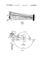
- FIG. 5 shows a view of the present invention.
- Reference light beam 60 from a light source 58 travels as indicated. The light strikes a beam splitter 62 and is divided into two paths 64 and 66. Path 64 passes through a reference White cell 68, a focusing optic 69, and the output is measured by detector 70. The path length of light through reference White cell 68 is identical to the path in air travelled by beam 66 prior to reaching detector 72.
- Light reflected off of beam splitter 62 along path 66 strikes sample S at point P and is reflected at near normal incidence to mirror M 2 .
- M 2 is a spherical mirror which reimages light back on sample S at point P and back along path 66 through beam splitter 62 to detector 72.
- mirror M 2 is not only spherical but has its center of curvature on the surface of S so that M 2 reimages light on the same spot on S for a second reflection.
- wavefront aberrations introduced in the first reflection are largely cancelled.
- This system is therefore insensitive to any power in S and is useful for measuring spherical, cylindrical, or aspheric as well as flat samples.
- the light should be focused to a small spot on the sample surface since light striking the right side of the spot initially will be reimaged on the left side by mirror M 2 so that cancellation of the figure induced changes in the wavefront is not complete unless the sample is a flat.
- mirror M 2 is swung around as shown by arc 74 and sample S is removed.
- new position 76 M 2 is at the virtual image position of M 2 formed by S as viewed at detector 72 through focusing optic 73.
- the total path length from beam splitter 62 to mirror M 2 is identical for the two configurations.
- Light travelling along beam 66 reflects off of mirror M 2 once for each configuration.
- the only difference in light is the fact that in the first configuration shown light reflects twice off of the sample.
- the White cell can be folded as shown in FIG. 4 to become a multiple pass absolute reflectometer. While the original purpose of the White cell was to increase path length, the folded White cell permits multiple reflections by inserting the folding mirror M s and moving M 1 and M 3 to intercept the reflected light. Refer back to FIG. 4 and the equation
- N values as high as 100 have been obtained in the laboratory for White cell work.
- the ratio would be 0.984. If 32 reflections are used, the ratio is 0.938. If the precision with which the ratio could be measured were ⁇ 0.002, a value which has been exceeded by a factor of four in some present systems, the statistical uncertainy in reflectance of the sample when 32 reflections are used is ⁇ 6 ⁇ 10 -5 . If systematic errors are eliminated, this system provides reflectance values for laser mirror reflectors which are 1 to 2 orders of magnitude better than using present equipment.
- the mirror to be tested is spherical it and M 2 are equivalent to a single fictitious mirror having a different focal length and position.
- the sample and M 1 or M 3 are equivalent to the same single mirror, since M s is equidistant from M 2 and M 1 or M 3 , all of which have the same radius of curvature.
- M 1 , M 2 , and M 3 are moved toward the sample by equal distances.
- convex mirrors they are moved away from the sample by equal distances.
- Off axis aberrations which may develop limit this technique, as well as the use of spherical mirrors in these systems, to near normal incidence.
- the modified White cell reflectometer cannot handle cylindrical optics. It can be used to measure the reflectance of flats over a large range of incident angles.
- M 1 , M 2 and M 3 form a conventional White cell.
- the signals to detectors 82 and 70 are balanced while in this position by adjusting reference White cell 68. Nearly equal air passage in the two White cells is necessary, but exact equality of signals to detectors 82 and 70 are not required since the function of detector 70 is only to follow detector 82 if source fluctuations occur and to provide a convenient reference signal for ratioing. The same relationship exists between detectors 70 and 72.
- a key feature of this reflectometer design is the requirement that the center of curvature of mirror M 2 be accurately either on the sample surface or in the surface defined by M 1 and M 3 .
- the position of M 2 should be set to within the focal range of the mirror as in the equation for F given above. Since the instrument is to be a scanning reflectometer, the surface of sample S must rotate and translate in the S plane.
- Desirable tolerances can be achieved using an air bearing rotary table 90 mounted in a concrete and steel weldment 92. Reflectometer optics are mounted on an air bearing track 94. Gross height adjustment is achieved by moving the air bearing slide on weldment 92. Fine adjustment is provided by motor driven jack screws 96. Sample S and the pallet 98 on which it rests are supported kinematically on air bearing rotary table 90. Air bearing tracks 94 also need to be aligned initially but they hold their position thereafter. Checks of the straightness of the track are made by autocollimation on the sample surface.
- TIS angular dependence of scattered light as well as total integrated scatter
- TIS detector 100 To make a measurement of angular dependence, a detector 102 moves on track 114 at 90° to the main track. By moving this cross track, which is also an air bearing, the entire area above the mirror is measured and the bidirectional reflectance distribution functions, BRDF, for the sample are determined.
- the advantage of the present system is that one does not need to know the reflectivity of mirrors M 1 , M 2 , or M 3 or of the reference White cell. Without the sample, it will be determined that one beam is a fixed percentage of the other. For purposes of example, let's assume that in FIG. 5 sample S is removed and mirrors M 1 and M 3 are placed in position 86 so that the beam intensity in path 66 is 90% of the beam intensity along path 64 through reference White cell as measured by detector 70 and 82. With M 1 and M 3 rotated back to the position shown in FIG. 5 and mirror M 2 moved forward to position 80, numerous reflections occur sufficient to decrease the level of light returning to detector 82 to be 80% of that measured by detector 70.
Abstract
An apparatus and method to measure the absolute reflectivity of a sample is made by use of a multiple pass reflectometer. A given light beam permits measurement of the absolute reflectivity by comparing a portion of the light beam in a reference White cell to the change in light of another portion of the beam which undergoes equivalent reflections except for the addition of the sample in one configuration as compared to the other.
Description
1. Field of the Invention
The present invention is for measuring specular reflectance from a given sample. In particular, it pertains to making absolute measurements with the reflectometer by the use of multiple pass reflections off of the sample. This permits high reflectivity samples to be accurately measured by repeating the number of reflections off the sample a known number of times.
2. Description of the Prior Art
U.S. Pat. No. 3,499,716 to Harold E. Bennett disclosed how to make specular reflections at nearly normal incidence. As was disclosed in the Bennett patent an absolute reflectometer can be made by a variation of a Strong absolute reflectometer as shown in FIG. 1. The strong reflectometer used a flat mirror for mirror 25 whereas the Bennett double reflection technique used a spherical mirror for mirror 25 of FIG. 1 and spherical mirrors 21 and 23 to reflect light off of sample S. The advantage of using spherical mirrors is that a slight sample tilt, as shown by a shift of sample S to position S', permits the deflected light beam to be reimaged to the same position. The use of a spherical mirror 25, having its center of curvature on the sample surface, results in the measurement being insensitive to sample tilt. A plane sample is shown in FIG. 1 and the center of curvature of mirror 25 is halfway between the location of the two beams striking the surface of sample S on the surface of sample S. Tilting the sample causes the light to follow the dotted lines and strike mirror 25 at a different location. However, since a spherical mirror used at its center of curvature returns light to the same point regardless of where it strikes the spherical mirror surface, on second reflection from the flat sample S, the error and tilt is exactly cancelled and the light leaves along the same path whether the sample is tilted or not.
FIG. 2 is a complete light ray path of the Bennett double reflection absolute reflectometer. Mirrors 22, 24, 26, 28, 30, 32, 34, 36, 38, 42, 44, and 46, are plane mirrors. Mirrors 19, 21, 23, 25, 27, 29, 31, 33, and 35 are spherical mirrors. For a detailed breakdown of how the prior Bennett reflectometer functions with regard to FIG. 2, the reader is referred to U.S. Pat. No. 3,499,716 which is herein incorporated by reference. In general, FIG. 2 can be described as comparing measurements with and without sample S for two different configurations. The first is with S as shown and with light reflected to detector D. Next, sample S is removed and the reflection path which is followed for mirrors 30 to 23 to S to 25 to S to 21 to 32 is now altered to have reflection along the path from 30 to 23 to 33 to 21 to 32. While equal path lengths are involved, it is noticed that for comparison purposes that mirrors 33 and 25 have to be either identical or interchangeable. If the sample is rotated 180° and mirrors 30 and 32 are interchanged, the following two measurements occur. Light first follows the dotted path for mirror 32 to 31 to S to 33 to S to 29 to 30 and with the sample removed light travels from 32 to 31 to 25 to 29 to 32. If mirrors 25 and 33 are identical, the ratio of the measurements with the sample in the light path to out of the light path gives the square of the sample reflectance directly. If mirrors 25 and 33 are not identical, they may be effectively interchanged by rotating the sample with mirrors 30 and 32 and measurements taken to obtain a second ratio. If the product of the two ratios is taken, it will give the fourth power of the absolute reflectance and the contribution from the non-identical mirrors cancels. The measurement statistics also improve since twice as many measurements are made as for a single configuration. As described previously, the system is insensitive to sample tilt, the most common source of error in reflectance measurements. The quoted accuracy for the system is ±0.1%.
A systematic error will arise in the double reflection system of FIG. 2 if the center of curvature of the spherical mirror is not accurately in the sample surface. The requirement for exact positioning is, from diffraction theory, that the center of curvature not be displaced from the sample surface by more than half the focal range of the mirror. The focal range F is given by F=4λf2 where f is the f number of the mirror, the ratio of focal length to the effective diameter of the sample opening for a parallel beam of incident light. λ represents the illuminating wavelength of light. For a f/l system, the requirement is that the center of the mirror coincide with the sample surface to within two wavelengths of light, a difficult requirement. The restrictions ease rapidly as the f number increases.
A simpler, prior art, form of absolute reflectometer is shown in FIG. 3. The reflectometer employs a single sample reflection and a movable detector 50 which swings about an axis 52 through the sample surface to pick up the "sample-in" and "sample-out" beams. The ratio of the two signals then determines the reflectance directly. The disadvantage of this system is that in addition to the requirement for accurately positioning the detector, the reflected beam is reversed left for right on the detector compared to the "straight through" position. Detector non-uniformities significantly limit the accuracy possible using a single reflectance absolute system. If the reflectance of a standard is known accurately, and the position of the sample and standard can be accurately adjusted to coincide, for example, by autocorrelation, the single reflectance technique can give reflectance values with high precision.
An alternate approach for measuring mirror reflectance with precision is to employ a White cell. White cell principles are shown in FIG. 4 for a folded White cell. FIG. 4 shows the principle of the White cell and its folded configuration. Mirrors M1 and M3 both have their centers of curvature on the surface of M2, whose center of curvature is centered between their surfaces. Incoming light is focused at point 0. It is reflected by the sample mirror MS to M1 at point 1. The dotted lines represent reflect angular dispersion of the light ray. Mirror M1 reimages point 0 on the surface of M2 at point 2. M2 in turn reflects this light to M3 at point 3 which reimages the focus again on the surface of M2 at point 4. Reflection continues to point 5 and point 6 in a similar manner. Reflected light then goes to M3 at point 7 where it is reimaged at point 8 and falls on a detector. By adjusting the tilt of M1 and M3, any odd number of reflections from M2 can be obtained. For highly reflecting mirrors, hundreds of passes between mirrors are possible. White cells were invented to produce very long path lengths in a gas filling the cell without exceeding the dimensions of the laboratory. They are also useful for obtaining multiple reflections on mirrors without losing light. The key to the performance of the White cell is mirror M2, which reimages the surfaces of M1 and M3, so that none of the light specularly reflected from these mirrors is lost. It thus plays a role similar to that played by mirror 25 in the double bounce reflectometer shown in FIGS. 1 and 2.
Let N=1,3,5 . . . the number of reflections on M2. Then the number of reflections for mirrors M1, M2, and M3 are 3, 7, 11 . . . 2N+1. There are initially three reflections and they increase by four every time thereafter. The ratio of the flux I emerging from the White cell to that entering it, IO, is
I/I.sub.O =R.sub.1.sup.(N+1)/2 R.sub.2.sup.N R.sub.3.sup.(N+1)/2 R.sub.s.sup.(2N+2)
If we take an average value R for mirrors M1, M2, and M3 and define it by
R.sup.4 =R.sub.1 R.sub.2.sup.2 R.sub.3,
the equation for I/IO can be written
I/I.sub.O =R.sub.s.sup.2N+2 R.sup.2N+1 N=1,3,5 . . . ,
where Rs =the reflectivity of the sample mirror and R1, R2, and R3 represent the reflectivity of mirrors M1, M2, and M3 respectively.
The multiple pass absolute reflectometer is made by having a reference light beam divided by a beam splitter. The two subsequent beams leaving the beam splitter are measured relative to one another. One beam in the splitter has passed through a reference White cell and is measured by a detector. The other beam from the beam splitter is subjected to multiple passes off of the sample and then measured by a detector. The detectors determine a relative comparison level between the two beams. The beam that has been multiply reflected off of the sample now undergoes the same number of reflections off of supporting mirrors except that the mirror orientation has now rotated such that with the sample removed the identical path length remains, only the reflections from the sample are omitted. Once again the reference level between the two detectors can be compared. The difference in reference levels between the detectors for the sample-in and sample-out configuration provides an absolute measure of the total light lost for the number of reflections off the sample.
By changing the relative location of supporting mirrors, two possible configurations for multiple pass measurements on a sample can be made. One configuration has a reference mirror with a spherical surface whose center of curvature is located on the sample surface. The second configuration matches the three mirror arrangement of a White cell and has the spherical mirrors reflecting off of a sample such that the center of curvature for the spherical mirror M2 is located between the two reference mirrors M1 and M3 of the standard White cell.
FIG. 1 is a prior art ray path for correcting for sample slip;
FIG. 2 is a prior art absolute reflectometer;
FIG. 3 is a ray path for a single reflection absolute reflectometer;
FIG. 4 is a ray path for a folded White cell;
FIG. 5 is a diagram of the present invention;
FIG. 6 is a side view of one embodiment of the present invention; and
FIG. 7 is a top view of FIG. 6.
FIG. 5 shows a view of the present invention. Reference light beam 60 from a light source 58 travels as indicated. The light strikes a beam splitter 62 and is divided into two paths 64 and 66. Path 64 passes through a reference White cell 68, a focusing optic 69, and the output is measured by detector 70. The path length of light through reference White cell 68 is identical to the path in air travelled by beam 66 prior to reaching detector 72. Light reflected off of beam splitter 62 along path 66 strikes sample S at point P and is reflected at near normal incidence to mirror M2. M2 is a spherical mirror which reimages light back on sample S at point P and back along path 66 through beam splitter 62 to detector 72. To do this, mirror M2 is not only spherical but has its center of curvature on the surface of S so that M2 reimages light on the same spot on S for a second reflection. On a second reflection from S, wavefront aberrations introduced in the first reflection are largely cancelled. This system is therefore insensitive to any power in S and is useful for measuring spherical, cylindrical, or aspheric as well as flat samples. The light should be focused to a small spot on the sample surface since light striking the right side of the spot initially will be reimaged on the left side by mirror M2 so that cancellation of the figure induced changes in the wavefront is not complete unless the sample is a flat.
To calibrate the reflectometer in the double reflection configuration just described, mirror M2 is swung around as shown by arc 74 and sample S is removed. In new position 76, M2 is at the virtual image position of M2 formed by S as viewed at detector 72 through focusing optic 73. The total path length from beam splitter 62 to mirror M2 is identical for the two configurations. Light travelling along beam 66 reflects off of mirror M2 once for each configuration. Thus, the only difference in light is the fact that in the first configuration shown light reflects twice off of the sample. By comparing the relative intensity of light in detectors 70 and 72 for each configuration, the difference in light lost when mirror M2 is in position 75 is due to two reflections off of the sample.
By mounting M2 on a slide on a rotatable bar with pivot point P on the surface of S, reflectance measurements at non-normal incidence may also be made. Arrows 85 and 87 show directions sample S can be moved through. Mirror M2 can then be moved about the arc shown to determine reflectance as a function of angle of incidence. For simplicity, S is assumed to rotate about an axis in the plane of the sample passing through P and normal to the drawing. It is also assumed to rotate about an axis normal to its surface and to translate along its surface so that the entire surface of the mirror can be scanned. For a large mirror, only the rotation normal to the mirror surface is performed by the sample mirror. The other motions are achieved by pivoting the input beam about point P and by moving P laterally rather than moving S.
For high reflectivity samples, a double pass reflectometer is insufficient. In modern laser devices, very high reflectivity of mirror surfaces is required. In reflectometers made previously, the number of reflections off the sample are insufficient to lower the amount of signal strength to an easily measured level. The White cell can be folded as shown in FIG. 4 to become a multiple pass absolute reflectometer. While the original purpose of the White cell was to increase path length, the folded White cell permits multiple reflections by inserting the folding mirror Ms and moving M1 and M3 to intercept the reflected light. Refer back to FIG. 4 and the equation
I/I.sub.O =R.sub.s.sup.2N+2 R.sup.2N+1 N=1,3,5 . . .
Mirrors M1 and M3 can be rotated about an axis P, which lies in the plane of the sample, until they coincide with their virtual images formed by Ms. By removing Ms, the value I'/I=R2N+1 is obtained. The White cell concept is used to develop an absolute reflectometer which gives powers of the reflectance of the sample to be measured. To a good approximation, the drop in signal from a high reflectance mirror which suffers X reflections is X times that for a single reflection. If N=5, for example, X=12 and for equal signal to noise ratios and linearity in the detectional electronics, the precision of measurement which is obtainable from a White cell type reflectometer should be better than that for a single bounce system by over an order of magnitude. N values as high as 100 have been obtained in the laboratory for White cell work. To take a numerical example, if the sample has a reflectance of 0.998 and eight reflections are used, the ratio would be 0.984. If 32 reflections are used, the ratio is 0.938. If the precision with which the ratio could be measured were ±0.002, a value which has been exceeded by a factor of four in some present systems, the statistical uncertainy in reflectance of the sample when 32 reflections are used is ±6×10⁻⁵. If systematic errors are eliminated, this system provides reflectance values for laser mirror reflectors which are 1 to 2 orders of magnitude better than using present equipment.
High sensitivity to atmospheric absorption is a serious limitation of the modified White cell reflectometer. Another limitation is the decrease in signal caused by multiple reflections from mirrors M1, M2, and M3, which may obscure the decreased signal caused by multiple reflections from the sample. Both limitations may be eliminated by using two White cells and making the system double beam. This approach is shown in FIG. 5 with mirrors M1 and M3 mounted on arm 78. Atmospheric path lengths in the sample and reference systems are identical, thus systematic error arising from atmospheric absorption is eliminated by this technique, and errors caused by mirror loss are minimized.
If the mirror to be tested is spherical it and M2 are equivalent to a single fictitious mirror having a different focal length and position. Similarly the sample and M1 or M3 are equivalent to the same single mirror, since Ms is equidistant from M2 and M1 or M3, all of which have the same radius of curvature. Thus to measure a concave spherical mirror M1, M2, and M3 are moved toward the sample by equal distances. For convex mirrors they are moved away from the sample by equal distances. Off axis aberrations which may develop limit this technique, as well as the use of spherical mirrors in these systems, to near normal incidence. Unlike the double reflection beam splitter reflectometer described earlier, the modified White cell reflectometer cannot handle cylindrical optics. It can be used to measure the reflectance of flats over a large range of incident angles.
The reflectometer design using a double reflection from the sample and a spherical mirror is a proven technique for making accurate reflectance measurements and can be used on all types of mirror samples including cylindrical mirrors. The modified White cell reflectometer offers the promise of the increased precision needed to test reflectance values of 0.9995 or better expected in the next generation of mirror coatings now being demonstrated. The major difference between a White cell reflectometer and a double reflection reflectometer is that in the latter the center of curvature of M2 is on the sample surface. In the modified White cell reflectometer, the center of curvature is midway between mirrors M1 and M3. To change the configuration of this reflectometer to that of a White cell system, M2, which is slide mounted, is moved along the bar as shown in FIG. 5 to position 80. S is tilted so that the incident beam strikes M1, and M1 and M2 are adjusted to give the desired number of images on M2. The multiply passed light in a White cell is now detected by a detector 82, which is mounted on the slide 77 holding M2. To make measurements as a function of angle of incidence, M1 and M3, which are slide mounted on a second bar 78 pivoted at P, are rotated along with S. To evaluate spherical mirrors, M2 and M1 are moved equal distances toward or away from S which is equidistant from both. For calibration, S is removed and M1 and M3 are rotated around arc 84 to positions 86 shown in FIG. 5. In position 86, M1, M2 and M3 form a conventional White cell. The signals to detectors 82 and 70 are balanced while in this position by adjusting reference White cell 68. Nearly equal air passage in the two White cells is necessary, but exact equality of signals to detectors 82 and 70 are not required since the function of detector 70 is only to follow detector 82 if source fluctuations occur and to provide a convenient reference signal for ratioing. The same relationship exists between detectors 70 and 72.
A key feature of this reflectometer design is the requirement that the center of curvature of mirror M2 be accurately either on the sample surface or in the surface defined by M1 and M3. For accurate results, the position of M2 should be set to within the focal range of the mirror as in the equation for F given above. Since the instrument is to be a scanning reflectometer, the surface of sample S must rotate and translate in the S plane.
In order for measurements of reflectance and scattered light to be made to the required accuracy over the entire mirror surface, it is necessary to support the mirror to be tested in an unstrained manner and to move either its surface or the test equipment without losing optical registration. The simplest way in which to support a sample S in a vibrationless manner is to use air pads or, if it is to be rotated, to use air bearings and to support it on its back.
One method of making the measurements as shown in FIG. 5 is the configuration shown in FIG. 6. Desirable tolerances can be achieved using an air bearing rotary table 90 mounted in a concrete and steel weldment 92. Reflectometer optics are mounted on an air bearing track 94. Gross height adjustment is achieved by moving the air bearing slide on weldment 92. Fine adjustment is provided by motor driven jack screws 96. Sample S and the pallet 98 on which it rests are supported kinematically on air bearing rotary table 90. Air bearing tracks 94 also need to be aligned initially but they hold their position thereafter. Checks of the straightness of the track are made by autocollimation on the sample surface. One method for checking that the track is parallel to the mirror surface is to use a Hewett-Packard 5501A doppler interferometer. Other techniques can be devised for this measurement. Although not essential, it is sometimes desirable to measure angular dependence of scattered light as well as total integrated scatter, TIS. TIS is measured by a TIS detector 100. To make a measurement of angular dependence, a detector 102 moves on track 114 at 90° to the main track. By moving this cross track, which is also an air bearing, the entire area above the mirror is measured and the bidirectional reflectance distribution functions, BRDF, for the sample are determined.
A top view of the sample support, showing the cross track, is given in FIG. 7. FIG. 7 is looking down on sample S. Like numbers refer to like components. Vertical supports 106 contain gross height adjusts 108. Beam steering mirrors 110 permit steering of the beam across the entire surface of sample S. To support BRDF detector 102 a slide counterweight 112 is mounted on crossarm 114 to support torque on crossarm 114 due to detector 102.
The advantage of the present system is that one does not need to know the reflectivity of mirrors M1, M2, or M3 or of the reference White cell. Without the sample, it will be determined that one beam is a fixed percentage of the other. For purposes of example, let's assume that in FIG. 5 sample S is removed and mirrors M1 and M3 are placed in position 86 so that the beam intensity in path 66 is 90% of the beam intensity along path 64 through reference White cell as measured by detector 70 and 82. With M1 and M3 rotated back to the position shown in FIG. 5 and mirror M2 moved forward to position 80, numerous reflections occur sufficient to decrease the level of light returning to detector 82 to be 80% of that measured by detector 70. This 10% drop represents an absolute value of loss due to N number of reflections off of the sample surface. Total percent of loss can then be straightforwardly calculated to determine the percentage of reflection on each individual reflection from sample S. If N=50, a loss of 0.2% occurs on each reflection. The reflectivity is determined to be 0.998.
It will be clear to those skilled in the art that numerous modifications of the above principle can be made for a multiple pass absolute reflectometer.
Claims (8)
1. An absolute reflectometer for a sample mirror or lens comprising:
a light source emitting a light beam along an optical path;
a beam splitter placed in said light beam for dividing said light beam into two paths, one of which illuminates said sample about a point;
a White cell placed in the other of said two paths for establishing a reference level of light intensity;
a spherical mirror placed so that said mirror's radius of curvature is on the surface of the sample mirror at said point of illumination to reflect light from said beamsplitter via said sample mirror back to said sample mirror and through said beamsplitter;
a detector placed in the path of light retroreflected through said beamsplitter for measuring the intensity of said retroreflected light; and
a pivoted arm mounted to said sample mirror for providing a path length for reflection of light when said sample mirror is removed which is equal to the path length when said sample mirror is present.
2. An absolute reflectometer as defined in claim 1 further comprising means for rotating and translating said sample mirror in a given plane, such that measurement of reflection from all sample mirror surface areas can be made.
3. A method of measuring reflection from a sample such as a mirror or lens comprising the steps of:
(a) emitting light along an optical path;
(b) dividing said light with a beamsplitter into two separate beams, a sample beam which illuminates said sample, and a reference beam;
(c) reflecting light from said sample due to said illumination beam back through said beamsplitter along the incoming path via said sample and through said beamsplitter with a spherical mirror such that a virtual image appears;
(d) placing a White cell in the path of the reference beam to make the path length of the reference beam equal to that of the sample beam;
(e) measuring the intensity of the reflected light passing through said beamsplitter with a detector;
(f) establishing the reference level of light through said White cell with a second detector;
(g) moving said spherical mirror to the virtual image location of said reflected light from said sample; and
(h) removing said sample so that the sample beam travels a path length equal to the distance travelled prior to the movement of said spherical mirror and the removal of said sample.
4. A method of measuring reflection from a sample as defined in claim 3 further comprising the steps of:
(i) shifting said sample through a given plane after measuring a given sample surface area in steps (a) through (h); and
(j) redoing steps (a) through (i) until all of said sample surface area has been measured.
5. A modified White cell for a multiple pass absolute reflectometer to measure a sample object such as a plane mirror, a spherical mirror, or lens, comprising:
a light source emitting a light beam along an optical path;
a beamsplitter placed in said optical path to divide said light beam into two separate beams, a sample beam which is incident on said sample, and a reference beam;
a plurality of mirrors arranged in a White cell configuration to reflect light in the sample beam back and forth for a predetermined number of reflections from said sample object;
a first detector placed in the path of light from said White cell configuration after it has been reflected off of said sample said predetermined number of times;
a reference White cell placed in the path of said reference beam for adjusting said reference beam to a predetermined path length;
a second detector placed after said reference White cell for measuring the amount of light emitted by said reference White cell; and
a pivoted arm for rotating some of said plurality of mirrors to a position where the light from said beamsplitter is otherwise incident on said sample object travels an equal path length when said sample object is removed, said removal and rotation providing an absolute basis to compare the light lost due to said predetermined number of reflections from said sample.
6. A modified White cell absolute reflectometer as defined in claim 5 further comprising means for rotating and translating said sample in a given plane, such that measurement of reflection from all sample surface areas can be made.
7. A method of measuring the absolute reflection loss from a sample object, such as a mirror or lens, due to multiple reflections from said sample object comprising the steps of:
(a) emitting light along an optical path;
(b) dividing said light with a beamsplitter into two separate beams, a sample beam which is incident on said sample, and a reference beam;
(c) arranging a plurality of mirrors to reflect light in the sample beam back and forth for a predetermined number of reflections from said sample;
(d) placing a detector in the path of said illuminating beam after it has undergone said predetermined number of reflections for measuring the intensity of light present;
(e) removing said sample;
(f) rearranging said plurality of mirrors to form a light path of equal length and with the same number of reflections from said plurality of mirrors, as in step c above but with no reflections from said sample;
(g) mounting a reference White cell in the path of the reference beam to establish a reference level for said light path of said first beam when said sample is removed; and
(h) measuring the light output of said reference White cell with a second detector such that said second detector provides a relative reference level for said first detector capable of adjusting for variations in said light source intensity.
8. The method of claim 7, further comprising the steps of:
(i) shifting said sample in a given plane after measuring a given sample surface area in steps (a) through (h); and
(j) repeating steps a through i until all of said sample surface area has been measured.
Priority Applications (1)
| Application Number | Priority Date | Filing Date | Title |
|---|---|---|---|
| US06/206,331 US4368983A (en) | 1980-11-13 | 1980-11-13 | Absolute reflectometer |
Applications Claiming Priority (1)
| Application Number | Priority Date | Filing Date | Title |
|---|---|---|---|
| US06/206,331 US4368983A (en) | 1980-11-13 | 1980-11-13 | Absolute reflectometer |
Publications (1)
| Publication Number | Publication Date |
|---|---|
| US4368983A true US4368983A (en) | 1983-01-18 |
Family
ID=22765898
Family Applications (1)
| Application Number | Title | Priority Date | Filing Date |
|---|---|---|---|
| US06/206,331 Expired - Lifetime US4368983A (en) | 1980-11-13 | 1980-11-13 | Absolute reflectometer |
Country Status (1)
| Country | Link |
|---|---|
| US (1) | US4368983A (en) |
Cited By (23)
| Publication number | Priority date | Publication date | Assignee | Title |
|---|---|---|---|---|
| FR2578047A1 (en) * | 1985-02-27 | 1986-08-29 | Louineau Andre | Method and device for monitoring the surface condition of a component, application to quality control of conducting or semiconducting thin films |
| US4770536A (en) * | 1986-12-04 | 1988-09-13 | Moshe Golberstein | Reflective photometry instrument |
| GB2227308A (en) * | 1989-01-13 | 1990-07-25 | Surface Inspection Ltd | Glossmeter |
| US6181427B1 (en) * | 1998-07-10 | 2001-01-30 | Nanometrics Incorporated | Compact optical reflectometer system |
| US20050001172A1 (en) * | 2003-01-16 | 2005-01-06 | Harrison Dale A. | Vacuum ultraviolet reflectometer system and method |
| US20050002037A1 (en) * | 2003-01-16 | 2005-01-06 | Harrison Dale A. | Vacuum ultraviolet referencing reflectometer |
| US20050001173A1 (en) * | 2003-01-16 | 2005-01-06 | Harrison Dale A. | Semiconductor processing techniques utilizing vacuum ultraviolet reflectometer |
| US20050006590A1 (en) * | 2003-01-16 | 2005-01-13 | Harrison Dale A. | Broad band referencing reflectometer |
| US20070181794A1 (en) * | 2004-08-11 | 2007-08-09 | Phillip Walsh | Method and apparatus for accurate calibration of a reflectometer by using a relative reflectance measurement |
| US20070181795A1 (en) * | 2004-08-11 | 2007-08-09 | Phillip Walsh | Method and apparatus for accurate calibration of a reflectometer by using a relative reflectance measurement |
| US20070181793A1 (en) * | 2004-08-11 | 2007-08-09 | Harrison Dale A | Method and apparatus for accurate calibration of VUV reflectometer |
| US20070215801A1 (en) * | 2004-08-11 | 2007-09-20 | Phillip Walsh | Method and apparatus for accurate calibration of a reflectometer by using a relative reflectance measurement |
| US7399975B2 (en) | 2004-08-11 | 2008-07-15 | Metrosol, Inc. | Method and apparatus for performing highly accurate thin film measurements |
| US20090079987A1 (en) * | 2007-09-25 | 2009-03-26 | Microsoft Corporation | Photodiode-based Bi-Directional Reflectance Distribution Function (BRDF) Measurement |
| US20090219537A1 (en) * | 2008-02-28 | 2009-09-03 | Phillip Walsh | Method and apparatus for using multiple relative reflectance measurements to determine properties of a sample using vacuum ultra violet wavelengths |
| DE102008046988A1 (en) * | 2008-09-12 | 2010-04-22 | [0X1] Software Und Consulting Gmbh | Reflectometer for characterizing materials or material surfaces, has optical radiation source, where material and/or material surface samples that are rotated around rotational axis to detect optical radiation resulting for rotation angles |
| US20100177324A1 (en) * | 2006-11-30 | 2010-07-15 | Metrosol, Inc. | Method and apparatus for optically measuring periodic structures using orthogonal azimuthal sample orientation |
| US20100277741A1 (en) * | 2007-04-09 | 2010-11-04 | Jordan Valley Semiconductors Ltd. | Combined optical metrology techniques |
| US20100290033A1 (en) * | 2003-01-16 | 2010-11-18 | Jordan Valley Semiconductors Ltd. | Method and System for Using Reflectometry Below Deep Ultra-Violet (DUV) Wavelengths for Measuring Properties of Diffracting or Scattering Structures on Substrate Work Pieces |
| US20100294922A1 (en) * | 2009-05-22 | 2010-11-25 | Hurst Jeffrey B | Automated calibration methodology for VUV metrology system |
| US8565379B2 (en) | 2011-03-14 | 2013-10-22 | Jordan Valley Semiconductors Ltd. | Combining X-ray and VUV analysis of thin film layers |
| US8867041B2 (en) | 2011-01-18 | 2014-10-21 | Jordan Valley Semiconductor Ltd | Optical vacuum ultra-violet wavelength nanoimprint metrology |
| US20220137162A1 (en) * | 2020-11-05 | 2022-05-05 | The Trustees Of Princeton University | System and method for femtotesla direct magnetic gradiometer using a multipass cell |
Citations (6)
| Publication number | Priority date | Publication date | Assignee | Title |
|---|---|---|---|---|
| US3160752A (en) * | 1963-02-19 | 1964-12-08 | Harold E Bennett | Reflectometer for measuring surface finishes |
| US3402634A (en) * | 1965-03-30 | 1968-09-24 | Navy Usa | Instrument for measuring absolute reflectance and transmittance at cryogenic temperatures |
| US3421079A (en) * | 1966-04-26 | 1969-01-07 | Us Navy | Measuring thin film thickness using interferometric-capacitance technique |
| US3499716A (en) * | 1966-05-27 | 1970-03-10 | Us Navy | Wide range absolute reflectometer |
| US3771880A (en) * | 1971-09-29 | 1973-11-13 | Us Navy | Roughness analyzer |
| US3947127A (en) * | 1974-11-11 | 1976-03-30 | The United States Of America As Represented By The Secretary Of The Navy | Optical component functional tester |
-
1980
- 1980-11-13 US US06/206,331 patent/US4368983A/en not_active Expired - Lifetime
Patent Citations (6)
| Publication number | Priority date | Publication date | Assignee | Title |
|---|---|---|---|---|
| US3160752A (en) * | 1963-02-19 | 1964-12-08 | Harold E Bennett | Reflectometer for measuring surface finishes |
| US3402634A (en) * | 1965-03-30 | 1968-09-24 | Navy Usa | Instrument for measuring absolute reflectance and transmittance at cryogenic temperatures |
| US3421079A (en) * | 1966-04-26 | 1969-01-07 | Us Navy | Measuring thin film thickness using interferometric-capacitance technique |
| US3499716A (en) * | 1966-05-27 | 1970-03-10 | Us Navy | Wide range absolute reflectometer |
| US3771880A (en) * | 1971-09-29 | 1973-11-13 | Us Navy | Roughness analyzer |
| US3947127A (en) * | 1974-11-11 | 1976-03-30 | The United States Of America As Represented By The Secretary Of The Navy | Optical component functional tester |
Non-Patent Citations (3)
| Title |
|---|
| Scattering Characteristics of Optical Materials by H. E. Bennett, vol. 17, No. 5, Optical Engineering, Sep.-Oct. 1978. * |
| Versatile High-Precision Multiple-Pass Reflectometer by O. Arnon and P. Beister, Applied Optics, vol. 17, No. 18, Sep. 15, 1978. |
| Versatile High-Precision Multiple-Pass Reflectometer by O. Arnon and P. Beister, Applied Optics, vol. 17, No. 18, Sep. 15, 1978. * |
Cited By (52)
| Publication number | Priority date | Publication date | Assignee | Title |
|---|---|---|---|---|
| FR2578047A1 (en) * | 1985-02-27 | 1986-08-29 | Louineau Andre | Method and device for monitoring the surface condition of a component, application to quality control of conducting or semiconducting thin films |
| US4770536A (en) * | 1986-12-04 | 1988-09-13 | Moshe Golberstein | Reflective photometry instrument |
| GB2227308A (en) * | 1989-01-13 | 1990-07-25 | Surface Inspection Ltd | Glossmeter |
| GB2227308B (en) * | 1989-01-13 | 1993-08-18 | Surface Inspection Ltd | Glossmeter |
| US6181427B1 (en) * | 1998-07-10 | 2001-01-30 | Nanometrics Incorporated | Compact optical reflectometer system |
| US20060208198A1 (en) * | 2003-01-16 | 2006-09-21 | Metrosol, Inc. | Vacuum ultraviolet reflectometer integrated with processing system |
| US8564780B2 (en) | 2003-01-16 | 2013-10-22 | Jordan Valley Semiconductors Ltd. | Method and system for using reflectometry below deep ultra-violet (DUV) wavelengths for measuring properties of diffracting or scattering structures on substrate work pieces |
| US20050001173A1 (en) * | 2003-01-16 | 2005-01-06 | Harrison Dale A. | Semiconductor processing techniques utilizing vacuum ultraviolet reflectometer |
| US20050006590A1 (en) * | 2003-01-16 | 2005-01-13 | Harrison Dale A. | Broad band referencing reflectometer |
| US7026626B2 (en) | 2003-01-16 | 2006-04-11 | Metrosol, Inc. | Semiconductor processing techniques utilizing vacuum ultraviolet reflectometer |
| US7067818B2 (en) | 2003-01-16 | 2006-06-27 | Metrosol, Inc. | Vacuum ultraviolet reflectometer system and method |
| US20060192958A1 (en) * | 2003-01-16 | 2006-08-31 | Metrosol, Inc. | Vacuum ultraviolet reflectometer having collimated beam |
| US20100051822A1 (en) * | 2003-01-16 | 2010-03-04 | Metrosol, Inc. | Broad band referencing reflectometer |
| US7126131B2 (en) | 2003-01-16 | 2006-10-24 | Metrosol, Inc. | Broad band referencing reflectometer |
| US20070030488A1 (en) * | 2003-01-16 | 2007-02-08 | Metrosol, Inc. | Broad band referencing reflectometer |
| US7189973B2 (en) | 2003-01-16 | 2007-03-13 | Metrosol, Inc. | Vacuum ultraviolet reflectometer integrated with processing system |
| US20050002037A1 (en) * | 2003-01-16 | 2005-01-06 | Harrison Dale A. | Vacuum ultraviolet referencing reflectometer |
| US8054453B2 (en) | 2003-01-16 | 2011-11-08 | Jordan Valley Semiconductors Ltd. | Broad band referencing reflectometer |
| US8014000B2 (en) | 2003-01-16 | 2011-09-06 | Jordan Valley Semiconductors Ltd. | Broad band referencing reflectometer |
| US7271394B2 (en) | 2003-01-16 | 2007-09-18 | Metrosol, Inc. | Vacuum ultraviolet reflectometer having collimated beam |
| US20100328648A1 (en) * | 2003-01-16 | 2010-12-30 | Jordan Valley Semiconductors Ltd. | Broad band referencing reflectometer |
| US20100290033A1 (en) * | 2003-01-16 | 2010-11-18 | Jordan Valley Semiconductors Ltd. | Method and System for Using Reflectometry Below Deep Ultra-Violet (DUV) Wavelengths for Measuring Properties of Diffracting or Scattering Structures on Substrate Work Pieces |
| US20080042071A1 (en) * | 2003-01-16 | 2008-02-21 | Metrosol, Inc. | Broad band referencing reflectometer |
| US7391030B2 (en) | 2003-01-16 | 2008-06-24 | Metrosol, Inc. | Broad band referencing reflectometer |
| US7394551B2 (en) | 2003-01-16 | 2008-07-01 | Metrosol, Inc. | Vacuum ultraviolet referencing reflectometer |
| US20050001172A1 (en) * | 2003-01-16 | 2005-01-06 | Harrison Dale A. | Vacuum ultraviolet reflectometer system and method |
| US7446876B2 (en) | 2003-01-16 | 2008-11-04 | Metrosol Inc. | Vacuum ultra-violet reflectometer with stray light correction |
| US7399975B2 (en) | 2004-08-11 | 2008-07-15 | Metrosol, Inc. | Method and apparatus for performing highly accurate thin film measurements |
| US7804059B2 (en) * | 2004-08-11 | 2010-09-28 | Jordan Valley Semiconductors Ltd. | Method and apparatus for accurate calibration of VUV reflectometer |
| US20070181794A1 (en) * | 2004-08-11 | 2007-08-09 | Phillip Walsh | Method and apparatus for accurate calibration of a reflectometer by using a relative reflectance measurement |
| US7663097B2 (en) | 2004-08-11 | 2010-02-16 | Metrosol, Inc. | Method and apparatus for accurate calibration of a reflectometer by using a relative reflectance measurement |
| US8119991B2 (en) | 2004-08-11 | 2012-02-21 | Jordan Valley Semiconductors Ltd. | Method and apparatus for accurate calibration of VUV reflectometer |
| US20070181795A1 (en) * | 2004-08-11 | 2007-08-09 | Phillip Walsh | Method and apparatus for accurate calibration of a reflectometer by using a relative reflectance measurement |
| US7511265B2 (en) | 2004-08-11 | 2009-03-31 | Metrosol, Inc. | Method and apparatus for accurate calibration of a reflectometer by using a relative reflectance measurement |
| US20070215801A1 (en) * | 2004-08-11 | 2007-09-20 | Phillip Walsh | Method and apparatus for accurate calibration of a reflectometer by using a relative reflectance measurement |
| US20100301225A1 (en) * | 2004-08-11 | 2010-12-02 | Jordan Valley Semiconductors Ltd. | Method and Apparatus for Accurate Calibration of VUV Reflectometer |
| US7282703B2 (en) | 2004-08-11 | 2007-10-16 | Metrosol, Inc. | Method and apparatus for accurate calibration of a reflectometer by using a relative reflectance measurement |
| US20070181793A1 (en) * | 2004-08-11 | 2007-08-09 | Harrison Dale A | Method and apparatus for accurate calibration of VUV reflectometer |
| US7990549B2 (en) | 2006-11-30 | 2011-08-02 | Jordan Valley Semiconductors Ltd. | Method and apparatus for optically measuring periodic structures using orthogonal azimuthal sample orientation |
| US20100177324A1 (en) * | 2006-11-30 | 2010-07-15 | Metrosol, Inc. | Method and apparatus for optically measuring periodic structures using orthogonal azimuthal sample orientation |
| US20100277741A1 (en) * | 2007-04-09 | 2010-11-04 | Jordan Valley Semiconductors Ltd. | Combined optical metrology techniques |
| US7929142B2 (en) * | 2007-09-25 | 2011-04-19 | Microsoft Corporation | Photodiode-based bi-directional reflectance distribution function (BRDF) measurement |
| US20090079987A1 (en) * | 2007-09-25 | 2009-03-26 | Microsoft Corporation | Photodiode-based Bi-Directional Reflectance Distribution Function (BRDF) Measurement |
| US7948631B2 (en) | 2008-02-28 | 2011-05-24 | Jordan Valley Semiconductors Ltd. | Method and apparatus for using multiple relative reflectance measurements to determine properties of a sample using vacuum ultra violet wavelengths |
| US20090219537A1 (en) * | 2008-02-28 | 2009-09-03 | Phillip Walsh | Method and apparatus for using multiple relative reflectance measurements to determine properties of a sample using vacuum ultra violet wavelengths |
| DE102008046988A1 (en) * | 2008-09-12 | 2010-04-22 | [0X1] Software Und Consulting Gmbh | Reflectometer for characterizing materials or material surfaces, has optical radiation source, where material and/or material surface samples that are rotated around rotational axis to detect optical radiation resulting for rotation angles |
| US20100294922A1 (en) * | 2009-05-22 | 2010-11-25 | Hurst Jeffrey B | Automated calibration methodology for VUV metrology system |
| US8153987B2 (en) | 2009-05-22 | 2012-04-10 | Jordan Valley Semiconductors Ltd. | Automated calibration methodology for VUV metrology system |
| US8867041B2 (en) | 2011-01-18 | 2014-10-21 | Jordan Valley Semiconductor Ltd | Optical vacuum ultra-violet wavelength nanoimprint metrology |
| US8565379B2 (en) | 2011-03-14 | 2013-10-22 | Jordan Valley Semiconductors Ltd. | Combining X-ray and VUV analysis of thin film layers |
| US20220137162A1 (en) * | 2020-11-05 | 2022-05-05 | The Trustees Of Princeton University | System and method for femtotesla direct magnetic gradiometer using a multipass cell |
| US11953569B2 (en) * | 2020-11-05 | 2024-04-09 | The Trustees Of Princeton University | System and method for femtotesla direct magnetic gradiometer using a multipass cell |
Similar Documents
| Publication | Publication Date | Title |
|---|---|---|
| US4368983A (en) | Absolute reflectometer | |
| CN104568389B (en) | Bilateral dislocation differential confocal component parameters measuring method | |
| US5015096A (en) | Method and apparatus for testing optical components | |
| US11578969B2 (en) | Optical assembly, method for producing data in the same, and method for manufacturing structure | |
| US20070263220A1 (en) | Optical Measurement System with Simultaneous Multiple Wavelengths, Multiple Angles of Incidence and Angles of Azimuth | |
| US3734626A (en) | Light apparatus for testing surfaces | |
| CN111044260B (en) | Microscope objective distortion testing device and testing method | |
| CN109358435B (en) | Device and method for adjusting perpendicularity of double telecentric lenses | |
| US4527893A (en) | Method and apparatus for optically measuring the distance to a workpiece | |
| US4285597A (en) | Goniophotometer for measuring the gloss and/or light diffusion of surfaces | |
| USRE32598E (en) | Feature extraction system for extracting a predetermined feature from a signal | |
| US2880644A (en) | Alignement interferometer | |
| US4390277A (en) | Flat sheet scatterometer | |
| AU663922B2 (en) | Improvements in or relating to surface curvature measurement | |
| JPH04504762A (en) | Method and apparatus for inspecting optical elements or systems | |
| US3602596A (en) | Roughness testing meters | |
| US4171910A (en) | Retroreflectance measurement system | |
| EP0128183B1 (en) | Inspection apparatus and method | |
| US4125778A (en) | Apparatus for laser anemometry | |
| US5355209A (en) | Device for measuring the diameter of an object that is largely cylindrical, for example an optical fiber, without contact | |
| US4120590A (en) | Method for measuring the thickness of transparent articles | |
| US20040196460A1 (en) | Scatterometric measuring arrangement and measuring method | |
| US5699164A (en) | Telecentric reflection head for optical monitor | |
| US4523842A (en) | Asperic surface test fixture | |
| US6081333A (en) | Bi-lateral shearing interferometer with beam convergence/divergence indication |
Legal Events
| Date | Code | Title | Description |
|---|---|---|---|
| AS | Assignment |
Owner name: UNITED STATES OF AMERICA, AS REPRESENTED BY THE SE Free format text: ASSIGNMENT OF ASSIGNORS INTEREST;ASSIGNOR:BENNETT HAROLD E.;REEL/FRAME:003833/0754 Effective date: 19801105 |
|
| STCF | Information on status: patent grant |
Free format text: PATENTED CASE |