US4400820A - Axial tomography head holder - Google Patents
Axial tomography head holder Download PDFInfo
- Publication number
- US4400820A US4400820A US06/430,149 US43014982A US4400820A US 4400820 A US4400820 A US 4400820A US 43014982 A US43014982 A US 43014982A US 4400820 A US4400820 A US 4400820A
- Authority
- US
- United States
- Prior art keywords
- head
- subject
- receptacle
- liner
- strap
- Prior art date
- Legal status (The legal status is an assumption and is not a legal conclusion. Google has not performed a legal analysis and makes no representation as to the accuracy of the status listed.)
- Expired - Fee Related
Links
- 238000003325 tomography Methods 0.000 title description 3
- 239000006260 foam Substances 0.000 claims abstract description 28
- 210000005069 ears Anatomy 0.000 claims abstract description 11
- 239000000463 material Substances 0.000 claims description 22
- 230000000452 restraining effect Effects 0.000 claims description 7
- 230000000087 stabilizing effect Effects 0.000 claims description 5
- 239000006261 foam material Substances 0.000 claims description 4
- 210000003128 head Anatomy 0.000 abstract description 135
- 210000001061 forehead Anatomy 0.000 abstract description 15
- 210000003679 cervix uteri Anatomy 0.000 description 7
- 210000000613 ear canal Anatomy 0.000 description 7
- 238000002591 computed tomography Methods 0.000 description 5
- 210000003625 skull Anatomy 0.000 description 5
- 238000000034 method Methods 0.000 description 4
- 210000001328 optic nerve Anatomy 0.000 description 4
- 239000004033 plastic Substances 0.000 description 3
- 229920003023 plastic Polymers 0.000 description 3
- JOYRKODLDBILNP-UHFFFAOYSA-N Ethyl urethane Chemical compound CCOC(N)=O JOYRKODLDBILNP-UHFFFAOYSA-N 0.000 description 2
- 238000011961 computed axial tomography Methods 0.000 description 2
- 238000010586 diagram Methods 0.000 description 2
- 239000000057 synthetic resin Substances 0.000 description 2
- 229920003002 synthetic resin Polymers 0.000 description 2
- 125000000391 vinyl group Chemical group [H]C([*])=C([H])[H] 0.000 description 2
- 229920002554 vinyl polymer Polymers 0.000 description 2
- 206010019196 Head injury Diseases 0.000 description 1
- 229920004142 LEXAN™ Polymers 0.000 description 1
- 239000004418 Lexan Substances 0.000 description 1
- 230000003190 augmentative effect Effects 0.000 description 1
- 210000004204 blood vessel Anatomy 0.000 description 1
- 210000004556 brain Anatomy 0.000 description 1
- 230000008878 coupling Effects 0.000 description 1
- 238000010168 coupling process Methods 0.000 description 1
- 238000005859 coupling reaction Methods 0.000 description 1
- 238000003384 imaging method Methods 0.000 description 1
- 210000003127 knee Anatomy 0.000 description 1
- 230000007935 neutral effect Effects 0.000 description 1
- 239000002985 plastic film Substances 0.000 description 1
- 239000004431 polycarbonate resin Substances 0.000 description 1
- 229920005668 polycarbonate resin Polymers 0.000 description 1
- 230000000284 resting effect Effects 0.000 description 1
- 238000009958 sewing Methods 0.000 description 1
- 230000036558 skin tension Effects 0.000 description 1
Images


Classifications
-
- A—HUMAN NECESSITIES
- A61—MEDICAL OR VETERINARY SCIENCE; HYGIENE
- A61B—DIAGNOSIS; SURGERY; IDENTIFICATION
- A61B6/00—Apparatus for radiation diagnosis, e.g. combined with radiation therapy equipment
- A61B6/04—Positioning of patients; Tiltable beds or the like
- A61B6/0407—Supports, e.g. tables or beds, for the body or parts of the body
- A61B6/0421—Supports, e.g. tables or beds, for the body or parts of the body with immobilising means
-
- A—HUMAN NECESSITIES
- A61—MEDICAL OR VETERINARY SCIENCE; HYGIENE
- A61B—DIAGNOSIS; SURGERY; IDENTIFICATION
- A61B6/00—Apparatus for radiation diagnosis, e.g. combined with radiation therapy equipment
- A61B6/50—Clinical applications
- A61B6/506—Clinical applications involving diagnosis of nerves
Definitions
- This invention relates to a holder for stabilizing the head of a subject who is prepared for undergoing a cranial X-ray examination.
- the holder is especially useful for computed axial tomography cranial examinations and will be described primarily in relation to that procedure.
- Computed tomography apparatus is used for obtaining X-ray attenuation data from a thin body layer for the purpose of enabling reconstruction of an X-ray image that allows the layer to be viewed in an axial perspective.
- Computed tomography apparatus comprises an X-ray tube located on one side of a human body undergoing an X-ray scan and a multiple-element X-ray detector located on the other side of the body.
- the X-ray tube and detector are mounted on a gantry and are driven rotationally about a horizontal longitudinal axis so the tube and detector orbit the X-ray examination subject jointly.
- the X-ray beam emitted from the focal spot of the X-ray tube is collimated into a thin diverging or fan-shaped beam whose thickness corresponds with the thickness of the layer in the body being scanned.
- a common mounting for the X-ray tube and multiple-element detector is part of the gantry which permits the mounting and, hence, the rotational plane of the tube and detector to be tilted about a laterally extending horizontal axis to which the longitudinal axis is perpendicular. This permits making a scan and obtaining X-ray attenuation data for an image of a transfer slice or layer of the body which is at an angle relative to the vertical and to the longitudinal axis.
- the subject is supported in a supine position on an elongated X-ray transmissive cradle.
- the cradle is translatable so it overhangs the base on which it is mounted in cantilever fashion.
- a head holder or restraint is mounted near the end of the cradle for the purpose of stabilizing and maintaining the subject's head in a fixed position during the relatively long time which is required for scanning several adjacent cranial cross-sections or layers. It is important for the head of the subject to not move during the scan of a layer and that the head be in the identical position for each one of the successive scans.
- both optic nerves appear simultaneously in one of the axial perspective layers.
- the geometrical relationship of the subject's head to the plane of the fan-shaped X-ray beam is usually determined before the final tomographic scan is made.
- the subject is pre-positioned so that when the scan is made there is reasonable certainty that both optic nerves will be in view.
- a change in the subject's position of as little as 2 mm can then defeat the objective of imaging both optic nerves fully in the same axial view.
- Some cranial X-ray studies may require the head of the subject to be in exactly the same position at the end of as much as forty minutes as at the beginning.
- the cranial study procedure involves making a computed projection radiograph which can be viewed to determine where and at what angle the fan-shaped scanning beam should be directed relative to the longitudinal axis of the subject's head. Minutes are often required in the decision-making process. As many as twenty layers may be scanned subsequently for obtaining the axial views.
- the cycle time per scan may be well under one minute, additional time may be consumed by waiting for an X-ray opaque medium which has been injected in the blood vessels to arrive at the proper place in the brain or cranium for getting the desired diagnostic information.
- Head holders that were available before the holder to be described later was invented have been found to be incapable of keeping the head of the subject in a precisely fixed position over a long period of time and are incapable of restoring the head to the predetermined desired position if there has been some movement over the long period.
- the new head holder is distinguished by its ability to induce the subject to relax and achieve a head position that can be comfortably maintained over a long period of time.
- the new head holder comprises a U-shaped X-ray transmissive receptacle (sometimes called a bucket) which has a liner or insert that is pre-formed and maintains a substantial U-shape and registers in the receptacle.
- the liner is composed of a resilient foam material, such as open cell urethane foam.
- the head of the subject When the head of the subject is placed within the U-shaped space in the foam liner and the liner is residing in the receptacle which is anchored to the X-ray table top and the head is strapped into the receptacle, the head will cause the resilient liner to conform and the subject can relax in that position.
- the head When the head is fixed in this position in the holder by using straps, the body is in its most relaxed position and the foam liner is somewhat compressed. The skin is movable over the skull so complete immobilization is impossible even if the head were strapped quite tightly. Moreover, it is impossible for the subject to maintain an absolutely fixed position.
- the new head holder is configured in such manner that it provides support behind the neck at an angle that corresponds to the natural angle of the cervical spine when a subject in in the holder.
- the holder receptacle is formed in a manner which allows the head to extend beyond the end of the cantilever X-ray subject supporting cradle without having the shoulders of the subject interfere with proper longitudinal positioning of the head.
- the resilient liner can be used as a head holer by itself, that is, without using the more rigid receptacle. This practice is one that may have to be followed in those cases where the subject may be uncooperative or violent as head trauma cases sometimes are and where further damage may result from angulation the cervical region as would occur if the rigid pre-formed receptacle were used.
- the new head holder is also designed in such fashion that it does not block sound passage to the subject's ears so the subject can be conversed with during the examination.
- the new head holder comprises a rigid generally U-shaped X-ray transmissive receptacle or bucket that has a concave bottom wall and laterally spaced apart integral side walls. Means are provided for mounting the receptacle to a body supporting cradle.
- a head restraint means comprising a thin sheet of flexible X-ray transmissive material, which can be performed into a U-shaped sheet desirably, is inserted in the U-shaped space in the receptacle and conforms with the contour of the space. Straps are fastened to the head restraint means and have free ends extending beyond its edges for being wrapped over the head of the subject and at least partially around the receptacle to restrain the head.
- a resilient foam liner is, however, first interposed between the thin head restraint means and the subject's head and the liner is sufficiently rigid to maintain its shape and sufficiently resilient to always restore the head to the original position in which it was fixed.
- Wedges are provided for being interposed between the head in the liner and the rigid receptacle to tilt the head down or up about a virtual tilt axis that coincides with an imaginary line between the external auditory canals of the left and right ears.
- FIG. 1 is a diagrammatic side elevation view showing a human subject supported on a longitudinally movable cantilever cradle wherein the subject's head is advanced into the X-ray beam path in a computed tomography scanner and wherein the head is supported in the new head holder;
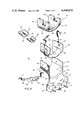
- FIG. 2 is an exploded perspective view of the head holder
- FIG. 3 is an enlarged perspective view of the head of a subject who is fastened in the head holder and ready for a tomographic examination;
- FIG. 4 shows a subject whose head is resting directly on the cantilever type cradle in which case the interior parts of the head holder are used and the receptacle which is part of the combination in the FIG. 2 and 3 embodiment is omitted;
- FIG. 5 is a plan view of the head holder detached from the subject supporting cradle
- FIG. 6 is a vertical section taken on a line corresponding with 6--6 in FIG. 5;
- FIG. 7 shows the head of the subject in the new head holder wherein the head is tilted forward by means of a wedge of one size
- FIG. 8 shows the head in the holder and tilted backward where the same sized wedge is used as in FIG. 9;
- FIG. 9 shows the subject's head in the holder and tilted forward by a greater amount than in FIG. 7 by reason of using a larger wedge.
- the human subject who is prepared for cranial axial tomography is indicated by the reference numeral 10.
- the subject is supported on an X-ray transmissive cradle 13.
- the cradle 13 can be translated inwardly or outwardly, that is, to the left and right as viewed in FIG. 1 for positioning the head of the subject in the plane of the fan-shaped X-ray beam whose central ray, looking at the beam from the edge is marked 14.
- the subject's head 15 is presently residing in the new head holder which is shown in outline in FIG. 1 and is designated generally by the reference numeral 16.
- the cervix 17 of the subject and the cervical spine therein are at their normal angle which, in a practical case is achieved by supporting the back of the subject in region 18 with a thin pillow, not shown and by having a pillow, not shown, inserted in the region 19 below the knees to bend them upwardly and relax them and allow the spine to be in an undeformed attitude as depicted in FIG. 1.
- a typical X-ray subject supporting cradle 13 to which the new head holder 16 may be attached is depicted in substantial detail in U.S. Pat. No. 4,262,204 which is assigned to the assignee of this application.
- the computed tomography gantry is designated generally by the reference numeral 20 and is shown diagrammatically.
- the gantry comprises a frame 21 that can tilt either left or right as viewed in FIG. 1 about a virtual horizontal axis or isocenter that is marked 22.
- the head of the subject is positioned so that the external ear canal is substantially coincident with the isocenter.
- Gantry 21 contains a diagrammatically illustrated X-ray tube 23 that has a focal spot 24 from which the X-ray beam is emitted toward the subject's head.
- the collimator for collimating the X-ray beam into a thin fan-shaped beam has been omitted from the diagram.
- the X-ray beam 14 penetrates the subject's head and is intercepted by a multiple cell X-ray detector 25 whose one end is symbolized by a dashed line rectangle in FIG. 1.
- the X-ray tube 23 and detector 25 are mounted on a turrent that rotates in the gantry and causes the X-ray tube and detector to orbit te subject's body jointly during an X-ray beam scan of a layer in the body or a part thereof such as the head.
- the X-ray tube and detector orbit about a longitudinal axis that intersects the transverse axis on which the gantry is tilted to form the isocenter 22.
- the new holder permits the head to be tilted forward or backward by using some wedges that are to be described.
- the head When the head is tilted with the wedges it rotates about a virtual center which is coincident with the external auditory canal.
- the technician performing the examinations uses an imaginary line drawn from the ear canal or virtual center to the edge of the eye as a reference line for determining the tilt angle of the head.
- a gantry 20 that is suitable for performing cranial axial tomography is illustrated in U.S. Pat. No. 4,112,303 and a typical multi-cell X-ray detector 25 is illustrated in U.S. Pat. No. 4,119,853. Both patents are assigned to the assignee of this application.
- the parts of the new head holder 16 are shown in the relationship in which they are assembled in the FIG. 2 exploded view to which attention is now invited.
- the holder comprises a rigid bucket or receptacle that is generally designated by the reference numeral 30.
- the receptacle is generally U-shaped and is molded in a single piece out of a material that has low X-ray attenuation properties.
- the material is polycarbonate resin which is obtainable from General Electric Company under its trademark "LEXAN.”
- the U-shaped receptacle has a curved or concave bottom wall 31 and upstanding parallel and laterally spaced apart side walls 32 and 33 which are integral with concave bottom wall 31.
- side walls 32 and 33 in conjunction with concave bottom wall 31 of the receptacle form the U-shaped configuration or space in which the head of the subject and some other components to be described can be accommodated.
- the extension 34 is angulated downwardly from the bottom 31 of the receptacle and the angle is such as to conform to the angle of the cervical spine of a normal subject lying supine on the cradle 13.
- the outside of the receptacle 30 is coated in part with a sheet of pile material 35 which is part of a fastening means known by the trademark "Velcro.”
- the pile sheet is split at its edge as indicated at 36 so it will lie smoothly against the bottom outside of the receptacle on which it is adhered.
- there are clear transparent area such as the one marked 37 on the side walls of the receptacle which permit visualizing the external auditory canal of the subject who is being examined with the head in the head holder Receptacle 30 terminates beyond the angulated cervix supporting extension 34 in a grooved margin 38 which allows it to fit onto the upper edge of an adapter plate 39.
- the receptacle may be seucred to the adapter plate by any suitable means such as by screws 40.
- the adapter plate 39 is for facilitating coupling the head holder receptacle 31 to the end of the cradle 13.
- the adapter is provided with at least two dowel pins 41 that fit into suitable holes, not shown, in the end of the cradle.
- Screw holes 42 are for screws that are used to secure the adapter for the free end of the cradle.
- the head holder assembly includes a head restraint means that is generally designated by the numeral 45.
- the head restraint means may comprise a flexible sheet 46 of X-ray transmissive material such as a transparent synthetic resin material that can be readily bent so it will conform with the U-shaped region of the head holder which is defined by its concave bottom wall 31 and its laterally spaced apart side walls 32 and 33. It is preferable to preform the thin plastic head restraint 46 sheet into a U-shaped configuration so it has a permanent set and will not have a tendency to spring open and lay flat as a simple plastic sheet will do.
- the head restraint member 46 will, however, be called a sheet for the sake of brevity.
- the head restraint sheet 45 is provided with a strap 47 which may be vinyl, by way of example and not limitation. This strap is otherwise known as a forehead strap. The ends of the strap have a band of hook material 48 and 49 or Velcro hook material adhered to them. In the preferred embodiment, the strap 47 is sewed at its center or intermediate its ends to the outside of the sheet 46. The region in which the sewing is done is marked 50. When the subject's head is in the head holder the free ends of the strap are wrapped around in opposite directions or crossed over the subject's forehead and the ends 48 and 49 that contain the hooks are engaged with the pile 35 on the receptacle 30.
- the head restraint sheet 45 is also provided with a pair of holes 51 and 52 that will align with the subject's external auditory canals when the subject's head is in the holder.
- the head holder assembly includes a liner or insert that is indicated generally by the reference numeral 55.
- the liner is preferably made from an open cell foam material such as urethane and the foam should have sufficient durometer for the liner to maintain the shape in which it appears in FIG. 2 when it is free standing and separated from the receptacle 30.
- the liner is spongy and resilient and has a tendency to restore its surfaces to their original shape when the surfaces are deformed by pressure that may be exerted by the head of the subject with which the liner directly interfaces which the head holder is in use.
- the liner 55 is an integral member comprised of a curved or concave bottom wall 56 that is confluent with or integral with laterally spaced apart and parallel side walls 57 and 58. Each side wall has a notch such as those marked 59 and 60. These notches are for accommodating the subject's ears when the head is residing in liner 55 and the liner is at least partially surrounded by head restraint sheet 45 and the head is in the holder. It will be evident that the open tops on the notches 59 and 60 provide open-ended channels by which sound can travel to the ears even though the liner 55 and head restraint sheet 45 are occupied by the subject's head and the head is residing in the U-shaped receptacle 30. Note that the front edge of the insertable liner 55 has a bevel 56' which will follow the contour of the cervix or the back of the head and provide a better fit.
- FIG. 2 two wedges are shown and they are indicated generally by the numerals 61 and 62.
- Wedges 61 and 62 are for tilting the subject's head rearwardly or forwardly before the head is secured prior to an X-ray beam scanning sequence. Use of the wedges will be discussed in somewhat more detail later in reference to FIGS. 8-10, primarily.
- a typical wedge 61 is composed of a fairly high durometer closed cell synthetic resin foam by way of example and not limitation.
- the wedges are preferably somewhat pliable and resilient for the sake of comfort but not sufficiently resilient or compressible to significantly deform when subjected to the pressure exerted by the subject's head when the head is in the holder.
- Typical wedge 61 has a circular outside periphery 63 and is basically a split cylinder.
- the interior of the cylinder is tapered from the thick end 64 in the longitudinal direction to the thin end 65.
- the radius of curvature of the outside periphery 63 is substantially the same as the radius of curvature of the concave or curved bottom wall 31 of the rigid receptacle 30 so the wedges will nest in conformity with the contour of the bottom wall 31 of the receptacle 30.
- FIG. 2 also shows a chin strap 68 that is used with the head holder.
- This strap may be vinyl or some other flexible material. It has two narrow free ends 69 and 70 which near their tips are provided with Velcro hook material 71 and 72 for engagement with the pile 35 on rigid receptacle 30.
- Chin strap 68 has a wider central region 73 in which there is a hole 74 into which the tip of the chin may extend for the purpose of augmenting stabilizing it and the head of the subject when the holder is in use.
- FIG. 5 A plan view of the assembled head holder is depicted in FIG. 5.
- the foam insert is bottomed in the U-shaped receptacle 30.
- the side walls 57 and 58 of the foam liner are interfaced with the thin preferably preformed into a U-shape plastic head restraining sheet 35 which is, in turn, interfaced with the side walls and bottom of the rigid receptacle 30.
- the restoring force thus developed in the liner due to its resilience tends to return the subject's head to the exact position in which it was when it was strapped down with the forehead strap 47 and the chin strap 68.
- the foam induces the head to go back to its relaxed position and, as mentioned earlier, wany stretching of the skin under the tight strap signals the subject to relax and let the resilient foam do the restoration.
- the plastic head restraining sheet provides an even circumferential pressure around the subject's skull, thereby providing rotational feedback to the subject.
- the foam liner 55 is slipped onto the subject's head or deposited in the rigid receptacle 30 over the head restraining sheet 45 before the subject's head is in the receptacle to avoid hurting the subject.
- the vertical section in FIG. 6 illustrates how the cervix region 34 of the rigid receptacle is angulated relative to the nominally longitudinally horizontal bottom of the receptacle 30. Note also in FIG. 6 that the ear hole 51 in the U-shaped head restraining sheet 45 aligns with the open-topped notch 59 or sound channel in the flexible foam insert wall 58.
- FIG. 3 shows the head of the subject in the holder and ready for X-ray scanning.
- Opposite ends of the forehead strap 47 are crossed-over and wrapped over the subject's forehead and the ends of this strap having the Velcro hooks are engaged with the pile 35 on the outside of the rigid receptacle 30.
- the head is positioned rotationally by exerting tension on the opposite strap ends as they are being attached to the Velcro pile 35.
- the forehead strap 47 is easily angled or set in a longitudinal position on the forehead to fit different forehead slants or shapes.
- the ears of the subject are in the recesses such as the one marked 60 that are provided in the side walls of the foam insert liner 55.
- the chin strap 68 is laid over the chin and its ends having the Velcro hooks 71 and 72 are engaged with the pile 35 on the receptacle.
- the chin is protruding into the hole 74 in the chin strap to enhance stability.
- the angulated portion 34 of the receptacle is right behind the cervix of the subject and the shoulders of the subject are brought right up to the end of the holder.
- the commercial embodiment is designed so that the back of the head is about ten centimeters above the plane of the patient supporting cradle 13 so that the cervical spine can assume its natural angle for the average subject.
- FIG. 7 is a diagram of a subject disposed in the head holder 16 for a very frequently used modality where the head is tilted slightly forward by reason of one of the less tapered closed cell foam wedges 62 having been inserted between the curved bottom of receptacle 30 and the outside bottom of the curved thin head restraint sheet 45.
- the exterior auditory canal is visible since the ear of the subject is residing in notch or recess 59 of foam liner 55 and the ear is behind the transparent wall of receptacle 30.
- the vertical line 83 is estimated by the radiologist with reference to the center 81 of the external auditory canal and the angle of tilt is determined by using the reference line 80 which is an imaginary line extending from center 81 to the corner of the eye.
- the chin strap 68 has its ends secured to Velcro pile 35 and the forehead strap 47 ends are crossed over on the forehead and attached to the Velcro. The subject is asked to assume a natural relaxed position while straps are being fastened so as to impart an initial deformation to the foam liner 55 which will, by reason of its resiliency, always restore the subject's head to its initial position in case there has been some movement and the subject relaxes.
- the thinner of the two wedges 62 is inserted with its taper pointed toward the top of the subject's head in which case the head tilts rearwardly.
- the examining technician determines the angle of tilt by estimating the angle between the reference line 80 between the auditory canal and corner of the eye and vertical line 84.
- the larger or more tapered wedge 61 is used such as would be used for a kyphotic or elderly patient who has a so-called dowager's hump.
- the larger wedge supports the cervix in its natural attitude for this type of subject.
- the tilt angle is determined by estimating the angle between the reference line 80 and vertical line 85 as in the previous examples.
- a computed projection radiograph is frequently made to provide an indication of where and at what angle the plane of the fan-shaped X-ray beam should have relative to the head of the subject.
- the computed projection radiograph is displayed on a television monitor, not shown, customarily so the radiologist or X-ray techinician can make a judgment as to the angle required for viewing the region of interest such as both optic nerves in the cranium.
- a wedge is inserted or not inserted as may be required.
- FIG. 4 shows what is done in such cases.
- the head restraint sheet 45 is used with the resilient foam liner 55 nested therein.
- the forehead strap 47 is crossed over the forehead of the subject.
- Velcro pile material strips 86 and 87 are adhered to the bottom of the table top 13 on which the subject is supported.
- the Velcro hook containing ends such as the one marked 48 on the forehead strap 47 engage with the fixed pile strips 86 to hold the subject's head down.
- the subject's head is in a relaxed or neutral state when the holder assembly is tied down.
- the skin is held by the strap but the skull can turn under the skin by about one-half inch.
- There is an original deformation of the resilient foam liner 55 which will provide the restoring force to the original position of the head after the head has moved and the subject becomes relaxed again. If the skin becomes tensioned by skull rotation the subject signalled to relax so the resilient foam liner can do its work.
Abstract
Description
Claims (15)
Priority Applications (1)
| Application Number | Priority Date | Filing Date | Title |
|---|---|---|---|
| US06/430,149 US4400820A (en) | 1982-09-30 | 1982-09-30 | Axial tomography head holder |
Applications Claiming Priority (1)
| Application Number | Priority Date | Filing Date | Title |
|---|---|---|---|
| US06/430,149 US4400820A (en) | 1982-09-30 | 1982-09-30 | Axial tomography head holder |
Publications (1)
| Publication Number | Publication Date |
|---|---|
| US4400820A true US4400820A (en) | 1983-08-23 |
Family
ID=23706263
Family Applications (1)
| Application Number | Title | Priority Date | Filing Date |
|---|---|---|---|
| US06/430,149 Expired - Fee Related US4400820A (en) | 1982-09-30 | 1982-09-30 | Axial tomography head holder |
Country Status (1)
| Country | Link |
|---|---|
| US (1) | US4400820A (en) |
Cited By (52)
| Publication number | Priority date | Publication date | Assignee | Title |
|---|---|---|---|---|
| US4463750A (en) * | 1983-01-26 | 1984-08-07 | Borschneck Anthony G | Traction device |
| US4571757A (en) * | 1984-07-10 | 1986-02-25 | Zolecki Donald L | Head restraining device for cervical support brace |
| US4655206A (en) * | 1984-03-02 | 1987-04-07 | Brian Moody | Spinal restraint |
| US4779858A (en) * | 1985-09-26 | 1988-10-25 | Gerinnove | Immobilizing apparatus for performing medical and paramedical procedures |
| US4979520A (en) * | 1987-12-21 | 1990-12-25 | Boone Jr Robert L | Pediatric device for immobilizing injured infant utilizing a standard size backboard |
| US4979519A (en) * | 1988-05-05 | 1990-12-25 | Board Of Regents, University Of Texas System | Head positioning system for accurate cranial alignment and dimension in magnetic resonance |
| US5027833A (en) * | 1990-03-06 | 1991-07-02 | Calkin Carston R | Extrication and spinal restraint device |
| US5036530A (en) * | 1989-10-23 | 1991-07-30 | A.T.F. Consolidated, Inc. | Emission tomography carousel system and method |
| US5207716A (en) * | 1992-03-13 | 1993-05-04 | Mcreynolds William U | Surgical head supporting and immobilizing apparatus |
| US5251629A (en) * | 1989-10-27 | 1993-10-12 | Hitachi, Ltd. | Inspection method and apparatus utilizing nuclear magnetic resonance |
| US5305754A (en) * | 1991-12-17 | 1994-04-26 | Honeywell Valerie S | Head immobilization device |
| US5311882A (en) * | 1993-07-08 | 1994-05-17 | Gagne George J | Tomography head restraint |
| US5337760A (en) * | 1992-11-25 | 1994-08-16 | Nichols Thomas K | Head holder for brain tomography |
| US5388580A (en) * | 1992-08-19 | 1995-02-14 | The United States Of America As Represented By The Department Of Health And Human Services | Head holder for magnetic resonance imaging/spectroscopy system |
| US5435323A (en) * | 1994-03-10 | 1995-07-25 | Rudy; Walter R. | Device and method for securing patient to trauma board |
| US5531229A (en) * | 1995-01-20 | 1996-07-02 | Dean; Richard D. | Body part immobilization device |
| DE29706436U1 (en) * | 1997-04-10 | 1997-05-28 | Mayr Robert | Skull positioning device for patient couch, in particular of X-ray or computer tomography systems |
| DE19640366A1 (en) * | 1996-09-30 | 1997-12-18 | Siemens Ag | X=ray diagnostic unit for standing patient |
| US5717735A (en) * | 1993-11-22 | 1998-02-10 | Hologic, Inc. | Medical radiological apparatus including optical crosshair device for patient positioning and forearm and spinal positioning aides |
| US5794628A (en) * | 1996-04-05 | 1998-08-18 | Dean; Richard D. | Thermoplastic positioning sling and method of fabrication thereof |
| US6000401A (en) * | 1997-10-16 | 1999-12-14 | Herrick Family Limited Partnership A California Limited Partnership | Anatomical apparatus for supporting a person's head |
| US6217214B1 (en) | 1993-11-22 | 2001-04-17 | Hologic, Inc. | X-ray bone densitometry apparatus |
| WO2001076403A1 (en) | 2000-04-09 | 2001-10-18 | William Mazzei | Protective cushion and cooperatively engageable helmet casing for anesthetized patient |
| US20030058997A1 (en) * | 2001-05-25 | 2003-03-27 | Scanwell Systems | Removable shielding for use during neurological examinations on a whole body pet scanner |
| US20040016057A1 (en) * | 2000-12-19 | 2004-01-29 | James Traut | Head immobilizer |
| US6704957B2 (en) | 2002-07-31 | 2004-03-16 | Steven L. Rhodes | Patient support pad for medical imaging equipment |
| US20050066444A1 (en) * | 2003-09-30 | 2005-03-31 | Dupaco, Inc. | Table engageable support for head cushion supporting anesthetized patient |
| US20050268381A1 (en) * | 2004-06-01 | 2005-12-08 | Balensiefer Eugene R | Wearable side impact protector |
| US20050284490A1 (en) * | 2004-06-25 | 2005-12-29 | Moyers Michael F | Method and device for registration and immobilization |
| US20060150984A1 (en) * | 2005-01-07 | 2006-07-13 | Ferguson Joe W | Surgical head fixation and positioning system |
| US20080042076A1 (en) * | 2003-08-12 | 2008-02-21 | Loma Linda University Medical Center | Modular patient support system |
| EP2179822A1 (en) * | 2008-10-24 | 2010-04-28 | KUKA Roboter GmbH | Holder device, medical robot and method for adjusting the tool centre points of a medical robot |
| US20100147313A1 (en) * | 2007-03-20 | 2010-06-17 | Samarit Medizintechnik Ag | Support for supporting a patient |
| US7789560B2 (en) | 2001-10-30 | 2010-09-07 | Loma Linda University Medical Center | Method and device for delivering radiotherapy |
| DE102009018570A1 (en) * | 2009-04-24 | 2010-10-28 | Carl Zeiss Industrielle Messtechnik Gmbh | Workpiece support for use in computer tomography scanner, has sensor made of foamed plastic and comprising recess and flat surface on side facing workpiece, where workpiece is arranged on sensor |
| US20110004135A1 (en) * | 2008-03-10 | 2011-01-06 | Kausek James H | Orthotic brace |
| WO2011104439A1 (en) * | 2010-02-23 | 2011-09-01 | Planmeca Oy | Patient support for an odontological x-ray apparatus |
| US8189889B2 (en) | 2008-02-22 | 2012-05-29 | Loma Linda University Medical Center | Systems and methods for characterizing spatial distortion in 3D imaging systems |
| US8210899B2 (en) | 2006-11-21 | 2012-07-03 | Loma Linda University Medical Center | Device and method for immobilizing patients for breast radiation therapy |
| US20130096417A1 (en) * | 2011-06-12 | 2013-04-18 | Dagmar Hering | Setup shell device, patient table comprising a setup shell device, and a medical imaging apparatus comprising a patient table and a setup shell device |
| WO2013075226A2 (en) * | 2011-11-26 | 2013-05-30 | Xlr Imaging Inc. | A subject placement and head positioning device |
| US20140076331A1 (en) * | 2012-09-16 | 2014-03-20 | David Colin Cho | C-spine head stabilization device |
| US20140163354A1 (en) * | 2012-12-12 | 2014-06-12 | Andrew J. Breth | Mri/cat scan patient arm support |
| WO2014088596A1 (en) * | 2012-12-07 | 2014-06-12 | Oraya Therapeutics, Inc. | Head support system |
| GB2519318A (en) * | 2013-10-16 | 2015-04-22 | Univ Cape Town | Stabilising kit |
| US9730763B2 (en) | 2014-10-17 | 2017-08-15 | Synaptive Medical (Barbados) Inc. | Head restraining apparatus for a medical procedure |
| US9913620B2 (en) | 2015-06-29 | 2018-03-13 | General Electric Company | Tilting head support for medical imaging |
| US10130542B1 (en) | 2010-09-17 | 2018-11-20 | Glenn Gerald Strawder | Device for positioning the neck of a person in the flexion and extension positions |
| US20190083050A1 (en) * | 2016-03-25 | 2019-03-21 | Carestream Health, Inc. | Cbct imaging system with curved detector |
| WO2020142564A1 (en) * | 2019-01-02 | 2020-07-09 | Yifat Jonathan | Patient head protection device |
| US20220338815A1 (en) * | 2019-10-03 | 2022-10-27 | Victoria Link Limited | Inflatable head support |
| US11937957B2 (en) | 2015-11-09 | 2024-03-26 | Radiaction Ltd. | Radiation shielding apparatuses and applications thereof |
Citations (4)
| Publication number | Priority date | Publication date | Assignee | Title |
|---|---|---|---|---|
| US3449570A (en) * | 1965-10-22 | 1969-06-10 | Philips Corp | X-ray table having a plurality of pairs of slings with oppositely windable members |
| US3897777A (en) * | 1974-05-23 | 1975-08-05 | Morrison Medical Products Comp | Head restraint |
| US4058112A (en) * | 1976-08-19 | 1977-11-15 | Johnson Robert M | Head positioner and arm rest for eye surgery |
| US4297994A (en) * | 1979-11-27 | 1981-11-03 | Bashaw Robert W | Cervical immobilizer |
-
1982
- 1982-09-30 US US06/430,149 patent/US4400820A/en not_active Expired - Fee Related
Patent Citations (4)
| Publication number | Priority date | Publication date | Assignee | Title |
|---|---|---|---|---|
| US3449570A (en) * | 1965-10-22 | 1969-06-10 | Philips Corp | X-ray table having a plurality of pairs of slings with oppositely windable members |
| US3897777A (en) * | 1974-05-23 | 1975-08-05 | Morrison Medical Products Comp | Head restraint |
| US4058112A (en) * | 1976-08-19 | 1977-11-15 | Johnson Robert M | Head positioner and arm rest for eye surgery |
| US4297994A (en) * | 1979-11-27 | 1981-11-03 | Bashaw Robert W | Cervical immobilizer |
Cited By (92)
| Publication number | Priority date | Publication date | Assignee | Title |
|---|---|---|---|---|
| US4463750A (en) * | 1983-01-26 | 1984-08-07 | Borschneck Anthony G | Traction device |
| US4655206A (en) * | 1984-03-02 | 1987-04-07 | Brian Moody | Spinal restraint |
| US4571757A (en) * | 1984-07-10 | 1986-02-25 | Zolecki Donald L | Head restraining device for cervical support brace |
| US4779858A (en) * | 1985-09-26 | 1988-10-25 | Gerinnove | Immobilizing apparatus for performing medical and paramedical procedures |
| US4979520A (en) * | 1987-12-21 | 1990-12-25 | Boone Jr Robert L | Pediatric device for immobilizing injured infant utilizing a standard size backboard |
| US4979519A (en) * | 1988-05-05 | 1990-12-25 | Board Of Regents, University Of Texas System | Head positioning system for accurate cranial alignment and dimension in magnetic resonance |
| JPH04507138A (en) * | 1989-10-23 | 1992-12-10 | エイ.ティ.エフ.コンソリデイテッド,インコーポレイテッド | Radiation tomography method and device |
| US5036530A (en) * | 1989-10-23 | 1991-07-30 | A.T.F. Consolidated, Inc. | Emission tomography carousel system and method |
| US5251629A (en) * | 1989-10-27 | 1993-10-12 | Hitachi, Ltd. | Inspection method and apparatus utilizing nuclear magnetic resonance |
| US5027833A (en) * | 1990-03-06 | 1991-07-02 | Calkin Carston R | Extrication and spinal restraint device |
| US5305754A (en) * | 1991-12-17 | 1994-04-26 | Honeywell Valerie S | Head immobilization device |
| US5207716A (en) * | 1992-03-13 | 1993-05-04 | Mcreynolds William U | Surgical head supporting and immobilizing apparatus |
| US5388580A (en) * | 1992-08-19 | 1995-02-14 | The United States Of America As Represented By The Department Of Health And Human Services | Head holder for magnetic resonance imaging/spectroscopy system |
| US5337760A (en) * | 1992-11-25 | 1994-08-16 | Nichols Thomas K | Head holder for brain tomography |
| US5311882A (en) * | 1993-07-08 | 1994-05-17 | Gagne George J | Tomography head restraint |
| US5717735A (en) * | 1993-11-22 | 1998-02-10 | Hologic, Inc. | Medical radiological apparatus including optical crosshair device for patient positioning and forearm and spinal positioning aides |
| US6217214B1 (en) | 1993-11-22 | 2001-04-17 | Hologic, Inc. | X-ray bone densitometry apparatus |
| US6009147A (en) * | 1993-11-22 | 1999-12-28 | Hologic, Inc. | X-ray bone densitometry |
| US5435323A (en) * | 1994-03-10 | 1995-07-25 | Rudy; Walter R. | Device and method for securing patient to trauma board |
| US5531229A (en) * | 1995-01-20 | 1996-07-02 | Dean; Richard D. | Body part immobilization device |
| US5794628A (en) * | 1996-04-05 | 1998-08-18 | Dean; Richard D. | Thermoplastic positioning sling and method of fabrication thereof |
| DE19640366A1 (en) * | 1996-09-30 | 1997-12-18 | Siemens Ag | X=ray diagnostic unit for standing patient |
| DE29706436U1 (en) * | 1997-04-10 | 1997-05-28 | Mayr Robert | Skull positioning device for patient couch, in particular of X-ray or computer tomography systems |
| US6000401A (en) * | 1997-10-16 | 1999-12-14 | Herrick Family Limited Partnership A California Limited Partnership | Anatomical apparatus for supporting a person's head |
| WO2001076403A1 (en) | 2000-04-09 | 2001-10-18 | William Mazzei | Protective cushion and cooperatively engageable helmet casing for anesthetized patient |
| US20040016057A1 (en) * | 2000-12-19 | 2004-01-29 | James Traut | Head immobilizer |
| US7120954B2 (en) * | 2000-12-19 | 2006-10-17 | Laerdal Medical Corporation | Head immobilizer |
| US20030058997A1 (en) * | 2001-05-25 | 2003-03-27 | Scanwell Systems | Removable shielding for use during neurological examinations on a whole body pet scanner |
| US6808308B2 (en) * | 2001-05-25 | 2004-10-26 | Scanwell Systems | Removable shielding for use during neurological examinations on a whole body pet scanner |
| US8376613B2 (en) | 2001-10-30 | 2013-02-19 | Loma Linda University Medical Center | Method and device for delivering radiotherapy |
| US8083408B2 (en) | 2001-10-30 | 2011-12-27 | Loma Linda University Medical Center | Method and device for delivering radiotherapy |
| US7789560B2 (en) | 2001-10-30 | 2010-09-07 | Loma Linda University Medical Center | Method and device for delivering radiotherapy |
| US6704957B2 (en) | 2002-07-31 | 2004-03-16 | Steven L. Rhodes | Patient support pad for medical imaging equipment |
| US20040162481A1 (en) * | 2002-07-31 | 2004-08-19 | Rhodes Steven L. | Medical imaging using patient support pads |
| US7013171B2 (en) | 2002-07-31 | 2006-03-14 | Rhodes Steven L | Medical imaging using patient support pads |
| US8981324B2 (en) | 2003-08-12 | 2015-03-17 | Loma Linda University Medical Center | Patient alignment system with external measurement and object coordination for radiation therapy system |
| US20110218679A1 (en) * | 2003-08-12 | 2011-09-08 | Loma Linda University Medical Center | Path planning and collision avoidance for movement of instruments in a radiation therapy environment |
| US8569720B2 (en) | 2003-08-12 | 2013-10-29 | Loma Linda University Medical Center | Patient alignment system with external measurement and object coordination for radiation therapy system |
| US20080042076A1 (en) * | 2003-08-12 | 2008-02-21 | Loma Linda University Medical Center | Modular patient support system |
| US8418288B2 (en) | 2003-08-12 | 2013-04-16 | Loma Linda University Medical Center | Modular patient support system |
| US7696499B2 (en) | 2003-08-12 | 2010-04-13 | Loma Linda University Medical Center | Modular patient support system |
| US8269195B2 (en) | 2003-08-12 | 2012-09-18 | Loma Linda University Medical Center | Patient alignment system with external measurement and object coordination for radiation therapy system |
| US8184773B2 (en) | 2003-08-12 | 2012-05-22 | Loma Linda University Medical Center | Path planning and collision avoidance for movement of instruments in a radiation therapy environment |
| US7746978B2 (en) | 2003-08-12 | 2010-06-29 | Loma Linda University Medical Center | Path planning and collision avoidance for movement of instruments in a radiation therapy environment |
| US8093569B2 (en) | 2003-08-12 | 2012-01-10 | Loma Linda University Medical Centre | Modular patient support system |
| US7949096B2 (en) | 2003-08-12 | 2011-05-24 | Loma Linda University Medical Center | Path planning and collision avoidance for movement of instruments in a radiation therapy environment |
| US7426763B2 (en) | 2003-09-30 | 2008-09-23 | Dupaco, Inc. | Table engageable support for head cushion supporting anesthetized patient |
| US20050066444A1 (en) * | 2003-09-30 | 2005-03-31 | Dupaco, Inc. | Table engageable support for head cushion supporting anesthetized patient |
| US20050268381A1 (en) * | 2004-06-01 | 2005-12-08 | Balensiefer Eugene R | Wearable side impact protector |
| US7316451B2 (en) * | 2004-06-01 | 2008-01-08 | Cosco Management, Inc. | Wearable side impact protector |
| US8479743B2 (en) | 2004-06-25 | 2013-07-09 | Loma Linda University Medical Center | Method and device for registration and immobilization |
| US7984715B2 (en) | 2004-06-25 | 2011-07-26 | Loma Linda University Medical Center | Method and device for registration and immobilization |
| US7073508B2 (en) | 2004-06-25 | 2006-07-11 | Loma Linda University Medical Center | Method and device for registration and immobilization |
| US20050284490A1 (en) * | 2004-06-25 | 2005-12-29 | Moyers Michael F | Method and device for registration and immobilization |
| US20140316183A1 (en) * | 2004-06-25 | 2014-10-23 | Loma Linda University Medical Center | Method and device for registration and immobilization |
| US20060150984A1 (en) * | 2005-01-07 | 2006-07-13 | Ferguson Joe W | Surgical head fixation and positioning system |
| US8523630B2 (en) | 2006-11-21 | 2013-09-03 | Loma Linda University Medical Center | Device and method for immobilizing patients for breast radiation therapy |
| US8210899B2 (en) | 2006-11-21 | 2012-07-03 | Loma Linda University Medical Center | Device and method for immobilizing patients for breast radiation therapy |
| US9084886B2 (en) | 2006-11-21 | 2015-07-21 | Loma Linda University Medical Center | Device and method for immobilizing patients for breast radiation therapy |
| US20100147313A1 (en) * | 2007-03-20 | 2010-06-17 | Samarit Medizintechnik Ag | Support for supporting a patient |
| US8578936B2 (en) * | 2007-03-20 | 2013-11-12 | Samarit Medical Ag | Support for supporting a patient |
| US8189889B2 (en) | 2008-02-22 | 2012-05-29 | Loma Linda University Medical Center | Systems and methods for characterizing spatial distortion in 3D imaging systems |
| US8737707B2 (en) | 2008-02-22 | 2014-05-27 | Robert D. Pearlstein | Systems and methods for characterizing spatial distortion in 3D imaging systems |
| US9196082B2 (en) | 2008-02-22 | 2015-11-24 | Loma Linda University Medical Center | Systems and methods for characterizing spatial distortion in 3D imaging systems |
| US20110004135A1 (en) * | 2008-03-10 | 2011-01-06 | Kausek James H | Orthotic brace |
| US8679042B2 (en) * | 2008-03-10 | 2014-03-25 | James H. Kausek | Orthotic brace |
| EP2179822A1 (en) * | 2008-10-24 | 2010-04-28 | KUKA Roboter GmbH | Holder device, medical robot and method for adjusting the tool centre points of a medical robot |
| DE102009018570A1 (en) * | 2009-04-24 | 2010-10-28 | Carl Zeiss Industrielle Messtechnik Gmbh | Workpiece support for use in computer tomography scanner, has sensor made of foamed plastic and comprising recess and flat surface on side facing workpiece, where workpiece is arranged on sensor |
| DE102009018570B4 (en) * | 2009-04-24 | 2018-12-20 | Carl Zeiss Industrielle Messtechnik Gmbh | Computer tomograph with a workpiece support for supporting a workpiece |
| EP2547260A4 (en) * | 2010-02-23 | 2014-06-25 | Planmeca Oy | Patient support for an odontological x-ray apparatus |
| EP2547260A1 (en) * | 2010-02-23 | 2013-01-23 | Planmeca Oy | Patient support for an odontological x-ray apparatus |
| US9456793B2 (en) | 2010-02-23 | 2016-10-04 | Planmeca Oy | Patient support for an odontological x-ray apparatus |
| CN102869307A (en) * | 2010-02-23 | 2013-01-09 | 普兰梅卡有限公司 | Patient support for an odontological X-ray apparatus |
| WO2011104439A1 (en) * | 2010-02-23 | 2011-09-01 | Planmeca Oy | Patient support for an odontological x-ray apparatus |
| CN102869307B (en) * | 2010-02-23 | 2015-09-23 | 普兰梅卡有限公司 | For the patient carrier of dentistry X-ray equipment |
| US10130542B1 (en) | 2010-09-17 | 2018-11-20 | Glenn Gerald Strawder | Device for positioning the neck of a person in the flexion and extension positions |
| US20130096417A1 (en) * | 2011-06-12 | 2013-04-18 | Dagmar Hering | Setup shell device, patient table comprising a setup shell device, and a medical imaging apparatus comprising a patient table and a setup shell device |
| WO2013075226A3 (en) * | 2011-11-26 | 2013-08-01 | Xlr Imaging Inc. | A subject placement and head positioning device |
| WO2013075226A2 (en) * | 2011-11-26 | 2013-05-30 | Xlr Imaging Inc. | A subject placement and head positioning device |
| US20140076331A1 (en) * | 2012-09-16 | 2014-03-20 | David Colin Cho | C-spine head stabilization device |
| US9056041B2 (en) * | 2012-09-16 | 2015-06-16 | David Colin Cho | C-spine head stabilization device |
| WO2014088596A1 (en) * | 2012-12-07 | 2014-06-12 | Oraya Therapeutics, Inc. | Head support system |
| US20140163354A1 (en) * | 2012-12-12 | 2014-06-12 | Andrew J. Breth | Mri/cat scan patient arm support |
| GB2519318B (en) * | 2013-10-16 | 2015-12-09 | Univ Cape Town | Stabilising kit |
| GB2519318A (en) * | 2013-10-16 | 2015-04-22 | Univ Cape Town | Stabilising kit |
| US9730763B2 (en) | 2014-10-17 | 2017-08-15 | Synaptive Medical (Barbados) Inc. | Head restraining apparatus for a medical procedure |
| US9913620B2 (en) | 2015-06-29 | 2018-03-13 | General Electric Company | Tilting head support for medical imaging |
| US11937957B2 (en) | 2015-11-09 | 2024-03-26 | Radiaction Ltd. | Radiation shielding apparatuses and applications thereof |
| US20190083050A1 (en) * | 2016-03-25 | 2019-03-21 | Carestream Health, Inc. | Cbct imaging system with curved detector |
| US10925552B2 (en) * | 2016-03-25 | 2021-02-23 | Carestream Health, Inc. | CBCT imaging system with curved detector |
| WO2020142564A1 (en) * | 2019-01-02 | 2020-07-09 | Yifat Jonathan | Patient head protection device |
| US20220338815A1 (en) * | 2019-10-03 | 2022-10-27 | Victoria Link Limited | Inflatable head support |
Similar Documents
| Publication | Publication Date | Title |
|---|---|---|
| US4400820A (en) | Axial tomography head holder | |
| US6704957B2 (en) | Patient support pad for medical imaging equipment | |
| US5040546A (en) | Patient positioning device and method | |
| US5388580A (en) | Head holder for magnetic resonance imaging/spectroscopy system | |
| US6355049B1 (en) | Head fixation apparatus | |
| US7792244B2 (en) | Breast compression for digital mammography, tomosynthesis and other modalities | |
| US20080103387A1 (en) | Breast Cancer Detection And Biopsy | |
| US4484571A (en) | Patient security and restraint system | |
| US4943986A (en) | Mammography compression apparatus for prosthetically augmented breast | |
| KR101510859B1 (en) | Head Fastening Device For Radiography | |
| US5771512A (en) | Nuclear image diagnosis apparatus having patient arm and head support | |
| JP2013520262A (en) | Patient support part of dental X-ray device | |
| US6618613B1 (en) | Non-axial body computed tomography | |
| US6210336B1 (en) | Damping cushion for ultrasound probes | |
| US20040218727A1 (en) | Mammography compression cushion system | |
| US4090079A (en) | Medical examining apparatus for the production of transverse sectional images | |
| JP7405401B2 (en) | Body positioning system | |
| WO2021084551A1 (en) | Cephalic stabilizing device with voice communication means | |
| CN219516333U (en) | Positioning structure convenient to wear | |
| JPH07328046A (en) | Radiography for spine and device thereof | |
| CN217592895U (en) | Head fixing device, examining table and medical imaging system | |
| JP7119963B2 (en) | Subject support device for nuclear medicine diagnostic equipment | |
| CN211187316U (en) | Head and neck fixing support for emergency patients | |
| CN216535281U (en) | Prone position chin support device and magnetic resonance scanning system comprising same | |
| CN219557349U (en) | Head support pad, head arm support and medical equipment |
Legal Events
| Date | Code | Title | Description |
|---|---|---|---|
| AS | Assignment |
Owner name: GENERAL ELECTRIC COMPANY A CORP.OF N Y Free format text: ASSIGNMENT OF ASSIGNORS INTEREST.;ASSIGNORS:ODELL, WILLIAM R.;FLETCHER, CHRISTINE M.;REEL/FRAME:004057/0026 Effective date: 19820929 Owner name: GENERAL ELECTRIC COMPANY, NEW YORK Free format text: ASSIGNMENT OF ASSIGNORS INTEREST;ASSIGNORS:ODELL, WILLIAM R.;FLETCHER, CHRISTINE M.;REEL/FRAME:004057/0026 Effective date: 19820929 |
|
| CC | Certificate of correction | ||
| PA | Patent available for licence or sale | ||
| MAFP | Maintenance fee payment |
Free format text: PAYMENT OF MAINTENANCE FEE, 4TH YEAR, PL 97-247 (ORIGINAL EVENT CODE: M173); ENTITY STATUS OF PATENT OWNER: LARGE ENTITY Year of fee payment: 4 |
|
| MAFP | Maintenance fee payment |
Free format text: PAYMENT OF MAINTENANCE FEE, 8TH YEAR, PL 97-247 (ORIGINAL EVENT CODE: M174); ENTITY STATUS OF PATENT OWNER: LARGE ENTITY Year of fee payment: 8 |
|
| FEPP | Fee payment procedure |
Free format text: MAINTENANCE FEE REMINDER MAILED (ORIGINAL EVENT CODE: REM.); ENTITY STATUS OF PATENT OWNER: LARGE ENTITY |
|
| LAPS | Lapse for failure to pay maintenance fees | ||
| FP | Lapsed due to failure to pay maintenance fee |
Effective date: 19950823 |
|
| STCH | Information on status: patent discontinuation |
Free format text: PATENT EXPIRED DUE TO NONPAYMENT OF MAINTENANCE FEES UNDER 37 CFR 1.362 |