US4401492A - Breast prosthesis and method of making the same - Google Patents

Breast prosthesis and method of making the same Download PDF

Info

Publication number
US4401492A
US4401492A US06/395,577 US39557782A US4401492A US 4401492 A US4401492 A US 4401492A US 39557782 A US39557782 A US 39557782A US 4401492 A US4401492 A US 4401492A
Authority
US
United States
Prior art keywords
breast
skin
mandrel
cast
resin
Prior art date
Legal status (The legal status is an assumption and is not a legal conclusion. Google has not performed a legal analysis and makes no representation as to the accuracy of the status listed.)
Expired - Lifetime
Application number
US06/395,577
Inventor
Arthur M. Pfrommer
Current Assignee (The listed assignees may be inaccurate. Google has not performed a legal analysis and makes no representation or warranty as to the accuracy of the list.)
Individual
Original Assignee
Individual
Priority date (The priority date is an assumption and is not a legal conclusion. Google has not performed a legal analysis and makes no representation as to the accuracy of the date listed.)
Filing date
Publication date
Application filed by Individual filed Critical Individual
Priority to US06/395,577 priority Critical patent/US4401492A/en
Application granted granted Critical
Publication of US4401492A publication Critical patent/US4401492A/en
Anticipated expiration legal-status Critical
Expired - Lifetime legal-status Critical Current

Links

Images

Classifications

    • AHUMAN NECESSITIES
    • A61MEDICAL OR VETERINARY SCIENCE; HYGIENE
    • A61FFILTERS IMPLANTABLE INTO BLOOD VESSELS; PROSTHESES; DEVICES PROVIDING PATENCY TO, OR PREVENTING COLLAPSING OF, TUBULAR STRUCTURES OF THE BODY, e.g. STENTS; ORTHOPAEDIC, NURSING OR CONTRACEPTIVE DEVICES; FOMENTATION; TREATMENT OR PROTECTION OF EYES OR EARS; BANDAGES, DRESSINGS OR ABSORBENT PADS; FIRST-AID KITS
    • A61F2/00Filters implantable into blood vessels; Prostheses, i.e. artificial substitutes or replacements for parts of the body; Appliances for connecting them with the body; Devices providing patency to, or preventing collapsing of, tubular structures of the body, e.g. stents
    • A61F2/50Prostheses not implantable in the body
    • A61F2/52Mammary prostheses
    • AHUMAN NECESSITIES
    • A61MEDICAL OR VETERINARY SCIENCE; HYGIENE
    • A61FFILTERS IMPLANTABLE INTO BLOOD VESSELS; PROSTHESES; DEVICES PROVIDING PATENCY TO, OR PREVENTING COLLAPSING OF, TUBULAR STRUCTURES OF THE BODY, e.g. STENTS; ORTHOPAEDIC, NURSING OR CONTRACEPTIVE DEVICES; FOMENTATION; TREATMENT OR PROTECTION OF EYES OR EARS; BANDAGES, DRESSINGS OR ABSORBENT PADS; FIRST-AID KITS
    • A61F2/00Filters implantable into blood vessels; Prostheses, i.e. artificial substitutes or replacements for parts of the body; Appliances for connecting them with the body; Devices providing patency to, or preventing collapsing of, tubular structures of the body, e.g. stents
    • A61F2/50Prostheses not implantable in the body
    • A61F2/5044Designing or manufacturing processes
    • A61F2/5046Designing or manufacturing processes for designing or making customized prostheses, e.g. using templates, finite-element analysis or CAD-CAM techniques
    • A61F2002/5053Designing or manufacturing processes for designing or making customized prostheses, e.g. using templates, finite-element analysis or CAD-CAM techniques using a positive or a negative model, e.g. casting model or mould
    • YGENERAL TAGGING OF NEW TECHNOLOGICAL DEVELOPMENTS; GENERAL TAGGING OF CROSS-SECTIONAL TECHNOLOGIES SPANNING OVER SEVERAL SECTIONS OF THE IPC; TECHNICAL SUBJECTS COVERED BY FORMER USPC CROSS-REFERENCE ART COLLECTIONS [XRACs] AND DIGESTS
    • Y10TECHNICAL SUBJECTS COVERED BY FORMER USPC
    • Y10STECHNICAL SUBJECTS COVERED BY FORMER USPC CROSS-REFERENCE ART COLLECTIONS [XRACs] AND DIGESTS
    • Y10S264/00Plastic and nonmetallic article shaping or treating: processes
    • Y10S264/30Use of anatomy in making a mold or using said mold
    • YGENERAL TAGGING OF NEW TECHNOLOGICAL DEVELOPMENTS; GENERAL TAGGING OF CROSS-SECTIONAL TECHNOLOGIES SPANNING OVER SEVERAL SECTIONS OF THE IPC; TECHNICAL SUBJECTS COVERED BY FORMER USPC CROSS-REFERENCE ART COLLECTIONS [XRACs] AND DIGESTS
    • Y10TECHNICAL SUBJECTS COVERED BY FORMER USPC
    • Y10TTECHNICAL SUBJECTS COVERED BY FORMER US CLASSIFICATION
    • Y10T156/00Adhesive bonding and miscellaneous chemical manufacture
    • Y10T156/10Methods of surface bonding and/or assembly therefor
    • Y10T156/1052Methods of surface bonding and/or assembly therefor with cutting, punching, tearing or severing
    • Y10T156/1056Perforating lamina
    • Y10T156/1057Subsequent to assembly of laminae

Definitions

  • This invention relates to the field of art of breast prostheses.
  • Prosthetic breasts have been well known for use after mastectomy operations.
  • these prior devices have left much to be desired in wearing comfort as well as an exact simulation of the removed breast, the area around the breast and the muscles under the arm in a radical mastectomy. Examples of some of the prior art can be seen in U.S. Pat. Nos. 2,482,297; 2,580,264; 2,752,602; 2,814,808; 2,851,692; 2,867,818; 3,196,464; 3,619,819; 3,811,133 and 4,086,666.
  • Prior devices have also been limited in their ability to duplicae appearance of the missing breast.
  • Prior devices have had their outer skin take on the shapes of various available mandrels. These mandrels have been made from molds of typical sized breasts, none of which were exact duplicates of the wearer's missing breast. Due to the expense of making customized mandrels, the wearer had to settle for a breast which was only a close facsimile of her missing breast.
  • a method of making a breast prosthesis comprises the steps of forming a negative cast of the wearer's remaining breast and the area of the missing breast.
  • a positive cast is formed of the negative cast and a model is made of the missing breast.
  • a flexible mold is formed over the modeled breast and a portion of the positive cast. The flexible mold and the modeled breast are removed together and turned over, with the back of the modeled breast facing up. An additional flexible mold is formed over the back of the modeled breast to form a rear wall of the prosthesis. The new wall is removed and the modeled breast is discarded.
  • the forward and rear walls are secured together and fiberglass resin fill is inserted into the interior space between the rear and forward walls to form a mandrel.
  • the mandrel is then removed from the flexible mold, sanded, and dipped into a liquid dispersion of silicone to form a skin surrounding the mandrel.
  • a flexible heat resistant backing sheet is secured to the mandrel to form a rear wall.
  • the form is again cured. Colorant is applied to the skin, and nipple and areola are modeled onto it. Filler is added between the edge of the skin and the backing to simulate the smooth surface curvature between the wearer's chest wall and breast.
  • the form is dipped into a clear liquid dispersion of silicone to form a second skin surrounding the first skin.
  • the form is again cured.
  • An opening is cut through rear of the backing sheet and the form is peeled from the mandrel. The opening is sealed and a gel fill is injected into the interior space.
  • FIG. 1 is a perspective view of the forward wall of the completed prosthesis
  • FIG. 2 is a cross sectional view of the prosthesis, filled with gel after completion
  • FIGS. 3A-B illustrate perspective views of a negative and a positive body cast of the wearer's body
  • FIG. 4 is a cross sectional view of the clay modeled breast surrounded by a rubber mold and a plastic holding cup;
  • FIG. 5 is a cross sectional view of the clay modeled breast turned upside down, with a mold of the breast's backwall on top;
  • FIG. 6 is a perspective view of the mandrel used for making the prosthesis, with a rod screwed into the mandrel;
  • FIGS. 7A-B are a top view and a side view of the sheets used to provide a backwall for the prosthesis during its construction.
  • FIG. 8 is a cross sectional view of the prosthesis taken at a step in the process before the mandrel is removed.
  • FIGS. 1 and 2 there is shown a breast prosthesis 60 which has been made by the method steps later described in detail with respect to FIGS. 3A-8.
  • Prosthesis 60 has a rear or body wall 48 which is effective to lock the prosthesis to the body and eliminate slipping and sliding which is particularly a problem when the wearer is very active.
  • rear or body wall 48 of prosthesis 60 is contoured as a result of the described molding process exactly to the area from which a breast has been removed. As a result of this exact contour, prosthesis 60 is maintained and locked in position whether the wearer is wearing a bra or not.
  • rear wall 48 has an opening 54 as shown in FIG. 2, which has been sealed with layers or rubber 55 and 56 and with buttom 57. The process of making the seal will be described in detail later.
  • Button 57 acts as a plug to prevent silicone gel fill 70 from escaping containment within forward wall 53 and rear wall 48. Also, button 57 permits the initial insertion of silicone gel fill 70.
  • the outer or forward resilient wall of prosthesis 60 is comprised of two skins: first skin 49 and second skin 53.
  • Skin 49 is color matched to the skin color of the wearer, and has nipple 51 and areola 52 constructed on it to match those of the wearer.
  • Second skin 53 is transparent and colorless. Consequently, the skin colors painted onto skin 49, nipple 51 and areola 52 show through second skin 53. The colors appear as though they were placed onto second skin 53.
  • Providing second skin 53 seals the skin colors and prevents nipple 51 and areola 52 from shifting or changing their colors.
  • second skin 53 adds strength to first skin 49, both increasing the longevity of prosthesis 60.
  • First skin 49 and second skin 53 have the same feel as the skin of the wearer and substantially the same softness since it is made of silicone rubber which has the same texture, softness and resiliency as a real breast.
  • fill 70 of the prosthesis is silicone gel which provides movement throughout the prosthesis as close as possible to a normal breast. In this way there is provided a breast prosthesis which comes as close as possible to the removed breast in color, softness, contour and movement.
  • prosthesis 60 is effectively locked in place due to the contour of rear wall 48.
  • the following is a series of method steps in the method of making a prosthesis 60.
  • a waste mold is cast of the woman's body to form a negative body cast 10.
  • the casting is done in pottery plaster of paris mixed with water and reinforced with fiberglass in conventional manner.
  • Body cast 10 extends from the waist 15 to shoulders 16 around neck 18 and includes clavicle 20.
  • Cast 10 includes the entire area around missing breast 21 together with remaining breast 11 (without bra) and under the arm adjacent to the missing breast.
  • Line 12 indicates an impression of lipstick mark which has been drawn on the woman's body to indicate the center line.
  • a positive body cast 30 is made of negative body cast 10.
  • This positive body cast is also made of pottery plaster of paris reinforced with fiberglass.
  • casts 10 and 30 may be separated by sodium silicate or water glass. Thereafter, cast 10 is chipped off and the remaining cast becomes a positive body cast 30, as shown in FIG. 3B having a positive impression 11a of breast 11 and positive impression 21a of missing breast 21. Positive impression 12a of lipstick mark 12 also appears on positive body cast 30.
  • the missing breast is then modeled in clay in a manner so that it matches breast 11a.
  • the modeling is done by a sculptor on top of area 21a and is done by eye.
  • the sculptor attempts to match breast 11a so that modeled breast 31, FIG. 4, is an almost exact copy of the missing breast based upon the sculptor's impression of positive cast breast 11a. Since cast 10 has been made without a bra, it will be understood that modeled breast 31 is being modeled to hang naturally without a bra.
  • a silicone rubber model 34 is then formed over modeled breast 31 on cast 30 to cover all of effective area 21a. Further, mold 34 may extend in particular examples, all the way up to the shoulder in order to blend the resultant prosthesis 60 onto the body of the wearer.
  • the silicon rubber may be Dow Corning "SILASTIC G" type silicon rubber which is relatively slow setting.
  • the thickness of mold 34 may be about 1/8 inch thick.
  • a support casting 38 is made in conventional manner of plaster of paris to cover rubber mold 34 and may be approximately 1/2 to 1/4 inch thick. As shown in FIG. 4, support casting 38 is flattened on the top for reason that will become apparent later. Support casting 38 is permitted to harden.
  • Support casting 38 silicon rubber 34 and clay modeled breast 31 are removed together from cast 30, and turned concave side up. Thus, support casting 38 is on the bottom, as shown in FIG. 5. Additional clay is taken and retaining wall 40 is constructed around the perimeter of plaster holding cup 38; retaining wall 40 is constructed to be approximately 3/4 inch high. A conventional release agent is sprayed onto clay 31, silicon rubber 34 and plaster holding cup 38, within the perimeter of retaining wall 40. Additional silicon rubber, such as "SILASTIC G" type silicon, is poured into the area within wall 40. In this manner, there is formed back wall 41 which conforms to the woman's body.
  • SILASTIC G silicon rubber
  • Back wall 41 is removed and clay modeled breast 31 is lifted from silicon rubber 34.
  • Back wall 41 is fitted back onto silicon rubber 34.
  • This cavity is filled with a fiberglass reinforced resin and permitted to cure.
  • the fiberglass reinforced resin forms a mandrel, as shown in FIG. 6.
  • Mandrel 44 is removed from silicon rubber 34 and 41.
  • Mandrel 44 is sanded and polished until it has a glass appearing finish.
  • mandrel 44 is made from fiberglass reinforced resin which is of the conventional type and requires a catalyst to harden.
  • the fiberglass reinforced resin is of the type suitable for use with car body repairs and is, therefore, easily sandable to form a smooth and shiny finish.
  • the fiberglass reinforced resin may be fiberglass reinforced resin No. 2595 made by Bond-Tite Division, Oatey Company, Cleveland, Ohio.
  • the mandrel is selected of material that can hold its shape while being subjected to heat. It is not, however, necessary that the mandrel be able to survive many heatings, since it will normally be subjected to only two heat cycles. Since the mandrel only needs to withstand two heat cycles, it is not necessary that it be made of expensive material such as aluminum. Consequently, this method permits selection of inexpensive material for the mandrel, allowing a custom designed breast prosthesis for each wearer.
  • Mandrel 44 As shown in FIG. 6, a hole is drilled into mandrel 44 by way of rear surface 43. Rod 42, approximately 4 inches in length, is taken and threaded at one end, as shown. Threaded end of rod 42 is then screwed into the mandrel. It will be understood that rod 42 may be attached to a metal bar to provide convenient means for holding mandrel 44. Mandrel 44, held by rod 42, is taken into the dipping room and immersed into a liquid dispersion made from silicone. The silicone dispersion is flesh colored and is of such material as GE SE4-552C or GE SE4-552K. The mandrel is dipped severl times into the liquid to form first skin 49, shown in FIG. 8. The number of dips is dependent on the size of the mandrel; the larger the mandrel, the more are the number of dips that are required. Typically, 7 to 12 dips are required.
  • Mandrel 44 is removed from the oven and rear of mandrel 43 is measured horizontally and vertically. Approximately 4 inches are added to these measurements.
  • a rectangular sheet of Kodel 46 or other heat resistant polyester sheeting material is cut, as shown in FIG. 7A, to conform to both the original measurements of rear of mandrel 43 plus the added 4 inches.
  • a calender is prepared with catalized raw rubber to a thickness of 25 mils. Kodel sheet 46 is then run through the calender in conventional manner, and coated with uncured rubber sheet 48, shown in FIG. 7B.
  • Hole 47 is punched through the center of Kodel sheet 46 and raw rubber 48. Hole 47 enables Kodel 46 and rubber 48 to fit over the previously placed rod 42 in mandrel 44.
  • Raw rubber 48 is pressed against the back of first skin 49, as shown in FIG. 8, causing it to adhere.
  • the product is then placed in an oven at 300° F. for approximately 30 minutes. This causes a vulcanizing action that makes a permanent bond between raw rubber 48 and first skin 49.
  • vulcanization is preferred over simple gluing because of the added strength.
  • Kodel is preferred, not only due to its heat resistant characteristics, but is also holds the shape of the backing in a rigid position and will not collapse when it comes in contact with the heat.
  • silicone rubber sealant 50 is applied in conventional manner to fill in the gap between the top edge of first skin 49 and backwall 48. Sealant 50 is manually shaped to form a smooth transition from backwall 48 down to first skin 49. Sealant 50 may be made from Dow Corning 732 or SWS RTV Silicone Rubber 951.
  • Backwall 48, sealant 50 and first skin 49 are artiscally sprayed with coatings of silicone, which are colored to resemble skin tone of the wearer.
  • silicone rubber tinted to the color of veins are painted onto first skin 49.
  • the sculptor also creates nipple 51 and areola 52.
  • colored silicone rubber is painted onto first skin 49 in area of the nipple and areola to simulate coloring of the wearer.
  • This painting material is in a semi-cured state, and is composed of silicone rubber sealant mixed with silicone color, such as silicone color manufactured by the Ferro Co. of Cleveland, O.
  • the form is again taken into the dipping room and immersed in a clear liquid dispersion of silicone rubber.
  • the form may be dipped three or more times so that it is sufficiently thick to maintain its shape.
  • the form is cured in an oven at approximately 300° F. and for approximately one hour. This process yields second skin 53 shown in FIG. 8.
  • the color of the form is permanently locked in. Further, by using a clear dispersion, the color is transparent to second skin 53 and appears as if it is on the surface, whereas in actuality it has three or more coats of silicone on top of it.
  • Mandrel 44 is now ready to be removed from the form.
  • a one-inch diameter hole 54 is made through backwalls 46 and 48 and through first skin 49, as shown in FIG. 8. It will be understood that hole 54 is made by simply widening hole 47, which was cut to permit mandrel rod 42 to fit through Kodel backing 46.
  • Mandrel 44 is removed from the form by stretching the silicone rubber skins over mandrel 44 in the same manner as one would remove rubber gloves from a hand.
  • the form is tested for any holes, using a high intensity light.
  • Kodel backing 46 is also removed at this stage. It will be understood that Kodel backing 46 must not be removed until second skin 53 and rear wall 48 have been cured (Step 11). Kodel backing 46 provides support to the form so that the form will retain its shape. After curing has occurred, rear wall 48 and second skin 53 will hold their shape without Kodel backing 46. Rear wall 48 is sufficiently thick to maintain the form of the woman's cavity formed by the missing breast while forward wall or second skin 53 remains soft and lifelike.
  • Hole 54 is ready to be sealed, using the following method:
  • a 30 mil sheet of clear silicone rubber such as 375 SWS, is cured in an oven in accordance with specification. Another 30 mil sheet of clear silicone rubber, however, uncured, is placed on top of the cured sheet. A third sheet of polyethylene is placed on top of the uncured sheet to protect it. These sheets, which are referred to as a large patch are then cut to exceed the size of hole 54, shown in FIG. 8.
  • a small button is made consisting of one layer of cured rubber, two layers of mesh, and two layers of uncured rubber with an added layer of polyethylene (for protection of the uncured rubber layers).
  • a small patch is also made consisting of a 30 mil sheet of uncured rubber with polyethylene layers placed on both sides for protection. The relative sizes of large patch 56, small patch 55 and button 57 can be seen in FIG. 2.
  • the "large" patch, small patch, and button are now ready to be glued together in the following manner.
  • the polyethylene is removed from the button.
  • Button 57 is placed, with its uncured side, in the center of the cured side of large patch 56.
  • the polyethylene layers are removed from the small patch, thus exposing the uncured rubber.
  • the polyethylene layer is also removed from the large patch, thus exposing the uncured rubber.
  • Small patch 55 is then placed in the center of large patch 56 as shown in FIG. 2.
  • button 57 and patches 55 and 56 are placed inside the chamber of prosthesis 60, as shown in FIG. 2.
  • the uncured side of large patch 56 is placed, as shown, abutting first skin 49, thus causing patch 56 to adhere to skin 49.
  • the form is then placed in an oven at 300° F. for 30 minutes, allowing vulcanization to occur.
  • the seal is now permanent, with button 57 acting as a stop valve, similar to a stop valve found in a football.
  • buttons 57 After button 57 has been placed in position and cured, prosthesis 60 is ready for filling. Silicone gel is inserted through button 57, shown in FIG. 2, with a large syringe.
  • the silicone gel may be 619 GE, SWS V114 or other gels, such as surgical gels made by Dow Corning.
  • Button 57 acts as a stop valve and prevents gel from escaping the inner walls of prosthesis 60.
  • fill may be added or removed as desired by use of a hypodermic needle inserted through button 57. This is particularly important if the wearer loses or gains weight. Such adding or removing is preferably performed by the maker of the unit.
  • prosthesis 60 As prosthesis 60 is being filled, it is placed so that the backwall 48 is tilted 45° with respect to vertical. The prosthesis is also cured in that position in an oven at 300° F. and for a minimum of six hours. By curing the gel in this position, gel filler 70 has a tendency to return to the same position in which it was cured. Consequently, regardless of the type of bra the wearer puts on, or how she handles the bra, prosthesis 60 will always return to its original shape and form.
  • negative body cast 10 is made of an unsupported breast and clay breast 31 is made to correspond with positive cast (unsupported) breast 11a.
  • modeled clay breast may be modeled in clay to represent a bra supported breast according to the eye of the sculptor.
  • a bilateral mastectomy the foregoing method steps may also be followed to produce a bilateral prosthesis with the following changes. Since both breasts have been removed, it would be necessary to model two clay breasts 31 on positive body cast 30. It will be understood that the breasts may be modeled as desired by the wearer and the sculptor.

Abstract

A method of making a mandrel for a breast prosthesis in which a negative cast is formed of the wearer's remaining breast and the area of the missing breast. A positive cast is formed of the negative cast and a model is made of the missing breast. A flexible mold is formed over the modeled breast and a portion of the positive cast. The flexible mold together with the molded breast are removed from the positive cast. An additional flexible mold is formed over the rear of the modeled breast to form a rear wall. The rear wall is removed and the modeled breast is discarded. The forward and rear walls are secured together to form a cavity. Fiberglass resin fill is inserted into the cavity and the resin is cured until it hardens to form the mandrel.

Description

This is a continuation of application Ser. No. 06/139,024, filed Apr. 10, 1980, now abandoned.
BACKGROUND OF THE INVENTION
A. Field of Invention
This invention relates to the field of art of breast prostheses.
B. Background Art
Prosthetic breasts have been well known for use after mastectomy operations. However, these prior devices have left much to be desired in wearing comfort as well as an exact simulation of the removed breast, the area around the breast and the muscles under the arm in a radical mastectomy. Examples of some of the prior art can be seen in U.S. Pat. Nos. 2,482,297; 2,580,264; 2,752,602; 2,814,808; 2,851,692; 2,867,818; 3,196,464; 3,619,819; 3,811,133 and 4,086,666.
One objection to prior devices has been in inability to duplicate the skin-tones of the natural breast and the color-action of the nipple and areola. The coloration has been provided on the surface of the prosthesis, thus deteriorating with usage.
Another objection to prior devices has been in inability to duplicate a smooth sloping curvature between the chest wall and the protruding natural breast. Prior devices have had a gap between the chest wall and the forward wall of the prosthesis, or have had an unnatural looking material placed in the gap. This has caused embarrassment to the wearer, especially when wearing a low-cut dress.
Prior devices have also been limited in their ability to duplicae appearance of the missing breast. Prior devices have had their outer skin take on the shapes of various available mandrels. These mandrels have been made from molds of typical sized breasts, none of which were exact duplicates of the wearer's missing breast. Due to the expense of making customized mandrels, the wearer had to settle for a breast which was only a close facsimile of her missing breast.
Still an additional objection to prior devices has been in discomfort to the wearer. These prior devices have deteriorated during use and have caused irritation and general discomfort to the wearer. Consequently, they could not be comfortably worn for an indefinite length of time without irritation.
It is the object of this invention to provide a method of making an artificial breast so that it will have the exact shape of the wearer's missing breast, will have the exact feel, color and skin tone of the wearer's natural breast, will maintain its appearance without deteriorating with usage, and will feel comfortable to the wearer over a substantially indefinite length of time.
SUMMARY OF THE INVENTION
A method of making a breast prosthesis comprises the steps of forming a negative cast of the wearer's remaining breast and the area of the missing breast. A positive cast is formed of the negative cast and a model is made of the missing breast. A flexible mold is formed over the modeled breast and a portion of the positive cast. The flexible mold and the modeled breast are removed together and turned over, with the back of the modeled breast facing up. An additional flexible mold is formed over the back of the modeled breast to form a rear wall of the prosthesis. The new wall is removed and the modeled breast is discarded. The forward and rear walls are secured together and fiberglass resin fill is inserted into the interior space between the rear and forward walls to form a mandrel. The mandrel is then removed from the flexible mold, sanded, and dipped into a liquid dispersion of silicone to form a skin surrounding the mandrel. After curing the skin, a flexible heat resistant backing sheet is secured to the mandrel to form a rear wall. The form is again cured. Colorant is applied to the skin, and nipple and areola are modeled onto it. Filler is added between the edge of the skin and the backing to simulate the smooth surface curvature between the wearer's chest wall and breast. The form is dipped into a clear liquid dispersion of silicone to form a second skin surrounding the first skin. The form is again cured. An opening is cut through rear of the backing sheet and the form is peeled from the mandrel. The opening is sealed and a gel fill is injected into the interior space.
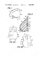
BRIEF DESCRIPTION OF DRAWINGS
FIG. 1 is a perspective view of the forward wall of the completed prosthesis;
FIG. 2 is a cross sectional view of the prosthesis, filled with gel after completion;
FIGS. 3A-B illustrate perspective views of a negative and a positive body cast of the wearer's body;
FIG. 4 is a cross sectional view of the clay modeled breast surrounded by a rubber mold and a plastic holding cup;
FIG. 5 is a cross sectional view of the clay modeled breast turned upside down, with a mold of the breast's backwall on top;
FIG. 6 is a perspective view of the mandrel used for making the prosthesis, with a rod screwed into the mandrel;
FIGS. 7A-B are a top view and a side view of the sheets used to provide a backwall for the prosthesis during its construction; and
FIG. 8 is a cross sectional view of the prosthesis taken at a step in the process before the mandrel is removed.
DETAILED DESCRIPTION
Referring to FIGS. 1 and 2, there is shown a breast prosthesis 60 which has been made by the method steps later described in detail with respect to FIGS. 3A-8.
Prosthesis 60 has a rear or body wall 48 which is effective to lock the prosthesis to the body and eliminate slipping and sliding which is particularly a problem when the wearer is very active. Specifically, rear or body wall 48 of prosthesis 60 is contoured as a result of the described molding process exactly to the area from which a breast has been removed. As a result of this exact contour, prosthesis 60 is maintained and locked in position whether the wearer is wearing a bra or not.
Further, rear wall 48 has an opening 54 as shown in FIG. 2, which has been sealed with layers or rubber 55 and 56 and with buttom 57. The process of making the seal will be described in detail later. Button 57 acts as a plug to prevent silicone gel fill 70 from escaping containment within forward wall 53 and rear wall 48. Also, button 57 permits the initial insertion of silicone gel fill 70.
The outer or forward resilient wall of prosthesis 60 is comprised of two skins: first skin 49 and second skin 53. The process of making both skins will be described later. Skin 49 is color matched to the skin color of the wearer, and has nipple 51 and areola 52 constructed on it to match those of the wearer. Second skin 53 is transparent and colorless. Consequently, the skin colors painted onto skin 49, nipple 51 and areola 52 show through second skin 53. The colors appear as though they were placed onto second skin 53. Providing second skin 53 seals the skin colors and prevents nipple 51 and areola 52 from shifting or changing their colors. Thus, the skin appearance of breast prosthesis 60 remains as originally designed for a substantially indefinite length of time. Furthermore, second skin 53 adds strength to first skin 49, both increasing the longevity of prosthesis 60.
First skin 49 and second skin 53 have the same feel as the skin of the wearer and substantially the same softness since it is made of silicone rubber which has the same texture, softness and resiliency as a real breast. In addition, fill 70 of the prosthesis is silicone gel which provides movement throughout the prosthesis as close as possible to a normal breast. In this way there is provided a breast prosthesis which comes as close as possible to the removed breast in color, softness, contour and movement. In addition, prosthesis 60 is effectively locked in place due to the contour of rear wall 48.
The following is a series of method steps in the method of making a prosthesis 60.
STEP 1
As shown in FIG. 3A, a waste mold is cast of the woman's body to form a negative body cast 10. The casting is done in pottery plaster of paris mixed with water and reinforced with fiberglass in conventional manner. Body cast 10 extends from the waist 15 to shoulders 16 around neck 18 and includes clavicle 20. Cast 10 includes the entire area around missing breast 21 together with remaining breast 11 (without bra) and under the arm adjacent to the missing breast. Line 12 indicates an impression of lipstick mark which has been drawn on the woman's body to indicate the center line.
STEP 2
A positive body cast 30 is made of negative body cast 10. This positive body cast is also made of pottery plaster of paris reinforced with fiberglass. In conventional manner, in the waste mold process, casts 10 and 30 may be separated by sodium silicate or water glass. Thereafter, cast 10 is chipped off and the remaining cast becomes a positive body cast 30, as shown in FIG. 3B having a positive impression 11a of breast 11 and positive impression 21a of missing breast 21. Positive impression 12a of lipstick mark 12 also appears on positive body cast 30.
STEP 3
The missing breast is then modeled in clay in a manner so that it matches breast 11a. The modeling is done by a sculptor on top of area 21a and is done by eye. The sculptor attempts to match breast 11a so that modeled breast 31, FIG. 4, is an almost exact copy of the missing breast based upon the sculptor's impression of positive cast breast 11a. Since cast 10 has been made without a bra, it will be understood that modeled breast 31 is being modeled to hang naturally without a bra.
STEP 4
A silicone rubber model 34 is then formed over modeled breast 31 on cast 30 to cover all of effective area 21a. Further, mold 34 may extend in particular examples, all the way up to the shoulder in order to blend the resultant prosthesis 60 onto the body of the wearer. The silicon rubber may be Dow Corning "SILASTIC G" type silicon rubber which is relatively slow setting. The thickness of mold 34 may be about 1/8 inch thick.
STEP 5
A support casting 38 is made in conventional manner of plaster of paris to cover rubber mold 34 and may be approximately 1/2 to 1/4 inch thick. As shown in FIG. 4, support casting 38 is flattened on the top for reason that will become apparent later. Support casting 38 is permitted to harden.
STEP 6
Support casting 38, silicon rubber 34 and clay modeled breast 31 are removed together from cast 30, and turned concave side up. Thus, support casting 38 is on the bottom, as shown in FIG. 5. Additional clay is taken and retaining wall 40 is constructed around the perimeter of plaster holding cup 38; retaining wall 40 is constructed to be approximately 3/4 inch high. A conventional release agent is sprayed onto clay 31, silicon rubber 34 and plaster holding cup 38, within the perimeter of retaining wall 40. Additional silicon rubber, such as "SILASTIC G" type silicon, is poured into the area within wall 40. In this manner, there is formed back wall 41 which conforms to the woman's body.
STEP 7
Back wall 41 is removed and clay modeled breast 31 is lifted from silicon rubber 34. Back wall 41 is fitted back onto silicon rubber 34. Thus, there is formed a cavity which conforms to the area removed by the surgeon; back wall 41 conforms to the woman's back part of the breast and forward wall 34 conforms to the woman's front part of the breast. This cavity is filled with a fiberglass reinforced resin and permitted to cure. The fiberglass reinforced resin forms a mandrel, as shown in FIG. 6. Mandrel 44 is removed from silicon rubber 34 and 41. Mandrel 44 is sanded and polished until it has a glass appearing finish.
It will be understood that mandrel 44 is made from fiberglass reinforced resin which is of the conventional type and requires a catalyst to harden. The fiberglass reinforced resin is of the type suitable for use with car body repairs and is, therefore, easily sandable to form a smooth and shiny finish. For example, the fiberglass reinforced resin may be fiberglass reinforced resin No. 2595 made by Bond-Tite Division, Oatey Company, Cleveland, Ohio.
It will also be understood that the mandrel is selected of material that can hold its shape while being subjected to heat. It is not, however, necessary that the mandrel be able to survive many heatings, since it will normally be subjected to only two heat cycles. Since the mandrel only needs to withstand two heat cycles, it is not necessary that it be made of expensive material such as aluminum. Consequently, this method permits selection of inexpensive material for the mandrel, allowing a custom designed breast prosthesis for each wearer.
STEP 8
As shown in FIG. 6, a hole is drilled into mandrel 44 by way of rear surface 43. Rod 42, approximately 4 inches in length, is taken and threaded at one end, as shown. Threaded end of rod 42 is then screwed into the mandrel. It will be understood that rod 42 may be attached to a metal bar to provide convenient means for holding mandrel 44. Mandrel 44, held by rod 42, is taken into the dipping room and immersed into a liquid dispersion made from silicone. The silicone dispersion is flesh colored and is of such material as GE SE4-552C or GE SE4-552K. The mandrel is dipped severl times into the liquid to form first skin 49, shown in FIG. 8. The number of dips is dependent on the size of the mandrel; the larger the mandrel, the more are the number of dips that are required. Typically, 7 to 12 dips are required.
To product is then taken to the oven for curing. It is cured at 300° F. for approximately one hour.
STEP 9
Mandrel 44 is removed from the oven and rear of mandrel 43 is measured horizontally and vertically. Approximately 4 inches are added to these measurements. A rectangular sheet of Kodel 46 or other heat resistant polyester sheeting material is cut, as shown in FIG. 7A, to conform to both the original measurements of rear of mandrel 43 plus the added 4 inches. A calender is prepared with catalized raw rubber to a thickness of 25 mils. Kodel sheet 46 is then run through the calender in conventional manner, and coated with uncured rubber sheet 48, shown in FIG. 7B.
Hole 47 is punched through the center of Kodel sheet 46 and raw rubber 48. Hole 47 enables Kodel 46 and rubber 48 to fit over the previously placed rod 42 in mandrel 44. Raw rubber 48 is pressed against the back of first skin 49, as shown in FIG. 8, causing it to adhere. The product is then placed in an oven at 300° F. for approximately 30 minutes. This causes a vulcanizing action that makes a permanent bond between raw rubber 48 and first skin 49.
It will be understood that vulcanization is preferred over simple gluing because of the added strength. Also, Kodel is preferred, not only due to its heat resistant characteristics, but is also holds the shape of the backing in a rigid position and will not collapse when it comes in contact with the heat.
STEP 10
After cooling, rear wall 48 and first skin 49 is ready for aesthetic touch-ups. To simulate smooth curvature of the area between the woman's chest and the top of her breast, silicone rubber sealant 50, as shown in FIG. 8, is applied in conventional manner to fill in the gap between the top edge of first skin 49 and backwall 48. Sealant 50 is manually shaped to form a smooth transition from backwall 48 down to first skin 49. Sealant 50 may be made from Dow Corning 732 or SWS RTV Silicone Rubber 951.
Backwall 48, sealant 50 and first skin 49 are artiscally sprayed with coatings of silicone, which are colored to resemble skin tone of the wearer. In addition, silicone rubber tinted to the color of veins are painted onto first skin 49. The sculptor also creates nipple 51 and areola 52. Thereafter, colored silicone rubber is painted onto first skin 49 in area of the nipple and areola to simulate coloring of the wearer. This painting material is in a semi-cured state, and is composed of silicone rubber sealant mixed with silicone color, such as silicone color manufactured by the Ferro Co. of Cleveland, O.
STEP 11
The form is again taken into the dipping room and immersed in a clear liquid dispersion of silicone rubber. The form may be dipped three or more times so that it is sufficiently thick to maintain its shape. Thereafter, the form is cured in an oven at approximately 300° F. and for approximately one hour. This process yields second skin 53 shown in FIG. 8.
In this manner, the color of the form is permanently locked in. Further, by using a clear dispersion, the color is transparent to second skin 53 and appears as if it is on the surface, whereas in actuality it has three or more coats of silicone on top of it.
STEP 12
Mandrel 44 is now ready to be removed from the form. A one-inch diameter hole 54 is made through backwalls 46 and 48 and through first skin 49, as shown in FIG. 8. It will be understood that hole 54 is made by simply widening hole 47, which was cut to permit mandrel rod 42 to fit through Kodel backing 46.
Mandrel 44 is removed from the form by stretching the silicone rubber skins over mandrel 44 in the same manner as one would remove rubber gloves from a hand. The form is tested for any holes, using a high intensity light.
Kodel backing 46 is also removed at this stage. It will be understood that Kodel backing 46 must not be removed until second skin 53 and rear wall 48 have been cured (Step 11). Kodel backing 46 provides support to the form so that the form will retain its shape. After curing has occurred, rear wall 48 and second skin 53 will hold their shape without Kodel backing 46. Rear wall 48 is sufficiently thick to maintain the form of the woman's cavity formed by the missing breast while forward wall or second skin 53 remains soft and lifelike.
STEP 13
Hole 54 is ready to be sealed, using the following method:
A 30 mil sheet of clear silicone rubber, such as 375 SWS, is cured in an oven in accordance with specification. Another 30 mil sheet of clear silicone rubber, however, uncured, is placed on top of the cured sheet. A third sheet of polyethylene is placed on top of the uncured sheet to protect it. These sheets, which are referred to as a large patch are then cut to exceed the size of hole 54, shown in FIG. 8. A small button is made consisting of one layer of cured rubber, two layers of mesh, and two layers of uncured rubber with an added layer of polyethylene (for protection of the uncured rubber layers). A small patch is also made consisting of a 30 mil sheet of uncured rubber with polyethylene layers placed on both sides for protection. The relative sizes of large patch 56, small patch 55 and button 57 can be seen in FIG. 2.
The "large" patch, small patch, and button are now ready to be glued together in the following manner. The polyethylene is removed from the button. Button 57 is placed, with its uncured side, in the center of the cured side of large patch 56. The polyethylene layers are removed from the small patch, thus exposing the uncured rubber. The polyethylene layer is also removed from the large patch, thus exposing the uncured rubber. Small patch 55 is then placed in the center of large patch 56 as shown in FIG. 2.
Using a needle to hold onto button 57 and patches 55 and 56, they are placed inside the chamber of prosthesis 60, as shown in FIG. 2. The uncured side of large patch 56 is placed, as shown, abutting first skin 49, thus causing patch 56 to adhere to skin 49. The form is then placed in an oven at 300° F. for 30 minutes, allowing vulcanization to occur. The seal is now permanent, with button 57 acting as a stop valve, similar to a stop valve found in a football.
STEP 14
After button 57 has been placed in position and cured, prosthesis 60 is ready for filling. Silicone gel is inserted through button 57, shown in FIG. 2, with a large syringe. The silicone gel may be 619 GE, SWS V114 or other gels, such as surgical gels made by Dow Corning. Button 57 acts as a stop valve and prevents gel from escaping the inner walls of prosthesis 60.
It will be understood that fill may be added or removed as desired by use of a hypodermic needle inserted through button 57. This is particularly important if the wearer loses or gains weight. Such adding or removing is preferably performed by the maker of the unit.
As prosthesis 60 is being filled, it is placed so that the backwall 48 is tilted 45° with respect to vertical. The prosthesis is also cured in that position in an oven at 300° F. and for a minimum of six hours. By curing the gel in this position, gel filler 70 has a tendency to return to the same position in which it was cured. Consequently, regardless of the type of bra the wearer puts on, or how she handles the bra, prosthesis 60 will always return to its original shape and form.
As previously described, negative body cast 10 is made of an unsupported breast and clay breast 31 is made to correspond with positive cast (unsupported) breast 11a. However, it will be understood that modeled clay breast may be modeled in clay to represent a bra supported breast according to the eye of the sculptor.
In a bilateral mastectomy, the foregoing method steps may also be followed to produce a bilateral prosthesis with the following changes. Since both breasts have been removed, it would be necessary to model two clay breasts 31 on positive body cast 30. It will be understood that the breasts may be modeled as desired by the wearer and the sculptor.

Claims (12)

What is claimed is:
1. A method for making a breast prosthesis comprising:
(a) forming a negative body cast of the body area comprising at least the missing breast;
(b) forming a positive cast from the negative cast and modeling a breast on the positive cast in the area of the missing breast;
(c) forming a negative mold over the modeled breast and adjacent portion of the positive body cast;
(d) removing the negative mold and modeled breast from the positive body cast;
(e) forming a back wall for the negative mold which conforms to the posterior contours of the modeled breast derived from the positive body cast;
(f) removing the back wall and the modeled breast from the negative mold and replacing the back wall to form a first cavity defined by the negative mold and back wall;
(g) filling the first cavity with a curable resin and curing the resin to form a heat-resistant mandrel conforming to the interior contours of said first cavity;
(h) removing the mandrel from the first cavity;
(i) coating the mandrel with a film-forming heat-curable silicone resin and curing the film-forming resin to form a shaped first skin on the mandrel;
(j) shaping a rear wall to the portion of the mandrel defining the posterior contours of the breast and bonding the shaped rear wall to the first skin;
(k) applying to the first skin a transparent film-forming resin and curing the applied resin to form a transparent protective second skin over the first skin;
(m) removing the mandrel from the shaped material through an aperture formed in the rear wall to form a second cavity defined by the first and second skins and rear wall;
(n) sealing the aperture in the rear wall; and
(o) filling this second cavity with a flexible material to complete the breast prosthesis.
2. The invention of claim 1, wherein the negative mold formed in step (c) is a flexible mold upon which a support casting is formed prior to removal of the negative mold and modeled breast from the positive body cast in step (d).
3. The invention of claim 2, wherein the back wall of the negative mold is formed by disposing a retaining wall on the support cast around the periphery of the posterior portion of the molded breast to define the perimeter of the back wall and filling the space defined by the retaining wall with a curable liquid resin.
4. The invention of claim 1, wherein the mandrel is coated in step (i) with a film-forming silicone resin curable at a temperature of at least about 300° F.
5. The invention of claim 4, wherein the first cavity is filled in step (g) with a fiberglass-reinforced curable resin and cured by action of a catalyst to form a mandrel resistant to temperatures of at least about 300° F.
6. The invention of claim 4, wherein the film-forming heat-curable silicone resin forming the first skin is flesh-colored.
7. The invention of claim 6, wherein the transparent film-forming resin applied to the first skin in step (k) is a clear liquid dispersion of silicone rubber.
8. The invention of claim 7, wherein the second cavity is filled in step (o) with a flexible material comprising a silicone gel.
9. The invention of claim 3, wherein the space defined by the retaining wall is filled with a curable liquid resin comprising a silicone rubber.
10. The invention of claim 5, wherein the rear wall in step (j) is shaped from raw rubber and is cured and bonded to the first skin by vulcanization.
11. The invention of claim 10, wherein a heat-resistant polyester backing is provided for the raw rubber to maintain its shape during vulcanization and wherein the backing is removed after vulcanization.
12. The method of claim 1, wherein after the rear wall is bonded to the first skin in step (j), a silicone rubber material is applied between the top edge of the first skin and the adjacent portion of the rear wall and shaped to form a smooth transition therebetween.
US06/395,577 1980-04-10 1982-07-06 Breast prosthesis and method of making the same Expired - Lifetime US4401492A (en)

Priority Applications (1)

Application Number Priority Date Filing Date Title
US06/395,577 US4401492A (en) 1980-04-10 1982-07-06 Breast prosthesis and method of making the same

Applications Claiming Priority (2)

Application Number Priority Date Filing Date Title
US13902480A 1980-04-10 1980-04-10
US06/395,577 US4401492A (en) 1980-04-10 1982-07-06 Breast prosthesis and method of making the same

Related Parent Applications (1)

Application Number Title Priority Date Filing Date
US13902480A Continuation 1980-04-10 1980-04-10

Publications (1)

Publication Number Publication Date
US4401492A true US4401492A (en) 1983-08-30

Family

ID=26836797

Family Applications (1)

Application Number Title Priority Date Filing Date
US06/395,577 Expired - Lifetime US4401492A (en) 1980-04-10 1982-07-06 Breast prosthesis and method of making the same

Country Status (1)

Country Link
US (1) US4401492A (en)

Cited By (44)

* Cited by examiner, † Cited by third party
Publication number Priority date Publication date Assignee Title
US4600551A (en) * 1984-05-21 1986-07-15 Erb Robert A Method for producing breast prostheses and supports
US4701230A (en) * 1985-07-18 1987-10-20 Nearly Me Method for manufacturing a breast prosthesis
US4787905A (en) * 1987-07-24 1988-11-29 Nearly Me Gel for breast prosthesis
EP0429029A2 (en) * 1989-11-17 1991-05-29 DEKUMED Gesellschaft für Kunststoff- und Medizintechnik mbH Method for producing a breast prosthesis
US5022942A (en) * 1987-05-27 1991-06-11 Mentor Corporation Method of making textured surface prosthesis implants
US5108686A (en) * 1991-03-15 1992-04-28 Griffin Joyce B Method of replicating a human nipple for use as a nursing device
US5171321A (en) * 1992-03-09 1992-12-15 Davis Joseph P Nipple prosthesis and method of making the same
US5231749A (en) * 1991-09-30 1993-08-03 Hutchison John H Method of making a unified interior and exterior design verification model
EP0617936A1 (en) * 1993-03-30 1994-10-05 Spenco Medical Corporation Encapsulated breast prosthesis and method of making same
US5458635A (en) * 1993-12-16 1995-10-17 Berman; Miriam B. Breast form
WO1996000048A1 (en) * 1994-06-23 1996-01-04 Janice Marie Thielbar Custom formed natural fit artificial breast appliance
WO1996003940A1 (en) * 1994-08-05 1996-02-15 Innovative Technologies Limited Mammary prostheses
US5700288A (en) * 1996-07-18 1997-12-23 The Board Of Trustees Of The University Of Arkansas Breast prosthesis
EP0815811A2 (en) * 1996-07-05 1998-01-07 Gehl, Gerolf, Dr. med. dent. Epithesis
US5855606A (en) * 1996-07-18 1999-01-05 Board Of Trustees Of The University Of Arkansas Breast prosthesis
WO1999012500A1 (en) * 1997-09-09 1999-03-18 Augmentec Aktiengesellschaft Implantologie-Epithetik Method for manufacturing an epithesis
WO1999020210A1 (en) * 1997-10-22 1999-04-29 Bio-Portraits, Inc. Custom external prosthetic apparatus and generating/positioning technique
US5902335A (en) * 1997-10-01 1999-05-11 Capital Marketing Technologies, Inc. Multiple section breast prosthesis
US5925282A (en) * 1993-12-23 1999-07-20 Coloplast A/S Method of manufacturing a foil-wrapped breast prosthesis and a shaping tool for use in performing the method
US6066220A (en) * 1997-05-03 2000-05-23 Thamert Orthopadische Hilfsmittel Gmbh & Co. Kg Process for producing a prosthesis for the female breast
US6086801A (en) * 1998-10-06 2000-07-11 Board Of Trustees Of The University Of Arkansas Method for forming a breast prosthesis
US6146419A (en) * 1999-05-13 2000-11-14 Board Of Trustees Of The University Method for forming a hollow prosthesis
US6156065A (en) * 1997-09-10 2000-12-05 Board Of Trustees Of The University Of Arkansas Natural fixation of breast prosthesis
US6162250A (en) * 1998-03-12 2000-12-19 Coloplast Corporation Self-forming partial breast prosthesis with encapsulated catalyst and a method of making the same
US6315796B1 (en) 1999-05-13 2001-11-13 Board Of Trustees Of The University Of Arkansas Flexible seamless memory tissue expanding implant
US6443986B1 (en) 1998-03-12 2002-09-03 Coloplast Corp Self-forming prosthetic device and method of making the same
US20020193878A1 (en) * 2001-02-21 2002-12-19 Bowman Roy Wade Two-layer external breast prosthesis with self-shaping feature and process for the manufacture thereof
US6520989B1 (en) 2000-01-18 2003-02-18 Board Of Trustees Of The University Of Arkansas Extreme volume flexible integrity prosthesis
US6623683B2 (en) * 2001-05-25 2003-09-23 Sato Giken Co., Ltd. Method for producing human body part prosthesis
US20030208269A1 (en) * 2002-05-03 2003-11-06 Eaton L. Daniel Methods of forming prostheses
US6660204B1 (en) 2000-09-01 2003-12-09 Otto Bock Orthopedic Industry, Inc. Custom prosthesis fabrication with in situ shaping of intermediate casting form
US20040156934A1 (en) * 2003-02-07 2004-08-12 Francalacci Franca Antonio Luis Breast mold
US20040167238A1 (en) * 2001-08-24 2004-08-26 Terrell W Ferguson Method for producing silicone foam utilizing a mechanical foaming agent
US20040176841A1 (en) * 2001-08-24 2004-09-09 Ferguson Terrell W. Medical prosthesis
US20040176493A1 (en) * 2001-08-24 2004-09-09 Ferguson Terrell W. Silicone foam
GB2460731A (en) * 2008-04-19 2009-12-16 East Kent Hospital Nhs Trust Artificial breast as a teat, soother or protector
US7879091B1 (en) * 2007-08-06 2011-02-01 Martin Inell O Inflatable prosthetic breast assembly and associated method
US20110120616A1 (en) * 2008-08-06 2011-05-26 Smith Wendy A Method of Forming a Breast Prosthesis
US8210899B2 (en) * 2006-11-21 2012-07-03 Loma Linda University Medical Center Device and method for immobilizing patients for breast radiation therapy
EP3222254A1 (en) * 2016-03-21 2017-09-27 Amoena Medizin-Orthopädie-Technik GmbH Breast prosthesis with closing plug for filling channel
US20190076137A1 (en) * 2012-07-24 2019-03-14 Omrix Biopharmaceuticals Ltd. Device and Method for the Application of a Curable Fluid Composition to a Bodily Organ
US11341685B2 (en) * 2019-05-03 2022-05-24 NipLips, LLC Color-matching body part to lip product
CN115384199A (en) * 2022-09-21 2022-11-25 陕西麦克斯韦医疗科技有限公司 Spray painting method, spray painting device and readable storage medium
WO2022248660A1 (en) * 2021-05-28 2022-12-01 Eve Borstprotheses B.V. System and method for making a breast prosthesis

Citations (6)

* Cited by examiner, † Cited by third party
Publication number Priority date Publication date Assignee Title
US1713751A (en) * 1927-04-11 1929-05-21 Dorogi Es Tarsa Gummigyar R T Thin-walled rubber articles and method of manufacturing same
US2543499A (en) * 1947-04-10 1951-02-27 Walter O Kausch Artificial breast
US3293663A (en) * 1963-08-12 1966-12-27 Dow Corning Surgically implantable human breast prosthesis
US3811133A (en) * 1972-08-31 1974-05-21 E Harris Weighted prosthetic breast
US4086666A (en) * 1976-04-30 1978-05-02 Petras Vaskys Breast prosthesis
US4125117A (en) * 1977-02-16 1978-11-14 Lee Denis C External breast prosthesis

Patent Citations (6)

* Cited by examiner, † Cited by third party
Publication number Priority date Publication date Assignee Title
US1713751A (en) * 1927-04-11 1929-05-21 Dorogi Es Tarsa Gummigyar R T Thin-walled rubber articles and method of manufacturing same
US2543499A (en) * 1947-04-10 1951-02-27 Walter O Kausch Artificial breast
US3293663A (en) * 1963-08-12 1966-12-27 Dow Corning Surgically implantable human breast prosthesis
US3811133A (en) * 1972-08-31 1974-05-21 E Harris Weighted prosthetic breast
US4086666A (en) * 1976-04-30 1978-05-02 Petras Vaskys Breast prosthesis
US4125117A (en) * 1977-02-16 1978-11-14 Lee Denis C External breast prosthesis

Cited By (64)

* Cited by examiner, † Cited by third party
Publication number Priority date Publication date Assignee Title
US4600551A (en) * 1984-05-21 1986-07-15 Erb Robert A Method for producing breast prostheses and supports
US4701230A (en) * 1985-07-18 1987-10-20 Nearly Me Method for manufacturing a breast prosthesis
US5022942A (en) * 1987-05-27 1991-06-11 Mentor Corporation Method of making textured surface prosthesis implants
US4787905A (en) * 1987-07-24 1988-11-29 Nearly Me Gel for breast prosthesis
EP0429029A3 (en) * 1989-11-17 1992-02-26 Firma Kunststofftechnik Degler Gmbh Method for producing a breast prosthesis
US5035758A (en) * 1989-11-17 1991-07-30 Kunststofftechnik Debler Gmbh Method of making a breast prosthesis
EP0429029A2 (en) * 1989-11-17 1991-05-29 DEKUMED Gesellschaft für Kunststoff- und Medizintechnik mbH Method for producing a breast prosthesis
US5108686A (en) * 1991-03-15 1992-04-28 Griffin Joyce B Method of replicating a human nipple for use as a nursing device
US5231749A (en) * 1991-09-30 1993-08-03 Hutchison John H Method of making a unified interior and exterior design verification model
US5171321A (en) * 1992-03-09 1992-12-15 Davis Joseph P Nipple prosthesis and method of making the same
EP0617936A1 (en) * 1993-03-30 1994-10-05 Spenco Medical Corporation Encapsulated breast prosthesis and method of making same
US5370688A (en) * 1993-03-30 1994-12-06 Spenco Medical Corporation Encapsulated gel breast prosthesis and method of making
US5458635A (en) * 1993-12-16 1995-10-17 Berman; Miriam B. Breast form
US5925282A (en) * 1993-12-23 1999-07-20 Coloplast A/S Method of manufacturing a foil-wrapped breast prosthesis and a shaping tool for use in performing the method
US5798062A (en) * 1994-06-23 1998-08-25 Thielbar; Janice Marie Method of making a custom formed natural fit artificial breast appliance
US5824075A (en) * 1994-06-23 1998-10-20 Thielbar; Janice Marie Custom formed natural fit artificial breast appliance
WO1996000048A1 (en) * 1994-06-23 1996-01-04 Janice Marie Thielbar Custom formed natural fit artificial breast appliance
WO1996003940A1 (en) * 1994-08-05 1996-02-15 Innovative Technologies Limited Mammary prostheses
EP0815811A2 (en) * 1996-07-05 1998-01-07 Gehl, Gerolf, Dr. med. dent. Epithesis
EP0815811A3 (en) * 1996-07-05 1998-10-28 Gehl, Gerolf, Dr. med. dent. Epithesis
US5700288A (en) * 1996-07-18 1997-12-23 The Board Of Trustees Of The University Of Arkansas Breast prosthesis
US5855606A (en) * 1996-07-18 1999-01-05 Board Of Trustees Of The University Of Arkansas Breast prosthesis
US6066220A (en) * 1997-05-03 2000-05-23 Thamert Orthopadische Hilfsmittel Gmbh & Co. Kg Process for producing a prosthesis for the female breast
WO1999012500A1 (en) * 1997-09-09 1999-03-18 Augmentec Aktiengesellschaft Implantologie-Epithetik Method for manufacturing an epithesis
US6156065A (en) * 1997-09-10 2000-12-05 Board Of Trustees Of The University Of Arkansas Natural fixation of breast prosthesis
US5902335A (en) * 1997-10-01 1999-05-11 Capital Marketing Technologies, Inc. Multiple section breast prosthesis
WO1999020210A1 (en) * 1997-10-22 1999-04-29 Bio-Portraits, Inc. Custom external prosthetic apparatus and generating/positioning technique
US6136027A (en) * 1997-10-22 2000-10-24 Otto Bock U.S., Inc. Custom prosthetic devices and methods of fabricating them using visible reverse imaging
US6162250A (en) * 1998-03-12 2000-12-19 Coloplast Corporation Self-forming partial breast prosthesis with encapsulated catalyst and a method of making the same
US6443986B1 (en) 1998-03-12 2002-09-03 Coloplast Corp Self-forming prosthetic device and method of making the same
USRE40487E1 (en) * 1998-10-06 2008-09-09 Board Of Trustees Of The University Of Arkansas Method for forming a breast prothesis
US6086801A (en) * 1998-10-06 2000-07-11 Board Of Trustees Of The University Of Arkansas Method for forming a breast prosthesis
US6283998B1 (en) 1999-05-13 2001-09-04 Board Of Trustees Of The University Of Arkansas Alloplastic vertebral disk replacement
US6146419A (en) * 1999-05-13 2000-11-14 Board Of Trustees Of The University Method for forming a hollow prosthesis
US6315796B1 (en) 1999-05-13 2001-11-13 Board Of Trustees Of The University Of Arkansas Flexible seamless memory tissue expanding implant
US6520989B1 (en) 2000-01-18 2003-02-18 Board Of Trustees Of The University Of Arkansas Extreme volume flexible integrity prosthesis
US6660204B1 (en) 2000-09-01 2003-12-09 Otto Bock Orthopedic Industry, Inc. Custom prosthesis fabrication with in situ shaping of intermediate casting form
US20020193878A1 (en) * 2001-02-21 2002-12-19 Bowman Roy Wade Two-layer external breast prosthesis with self-shaping feature and process for the manufacture thereof
US7575596B2 (en) 2001-02-21 2009-08-18 Amoena Medizin-Orthopädie-Technik GmbH Two-layer external breast prosthesis with self-shaping feature and process for the manufacture thereof
US6623683B2 (en) * 2001-05-25 2003-09-23 Sato Giken Co., Ltd. Method for producing human body part prosthesis
US6818673B2 (en) 2001-08-24 2004-11-16 Radiant Holdings, Llc Method for producing silicone foam utilizing a mechanical foaming agent
US20040176841A1 (en) * 2001-08-24 2004-09-09 Ferguson Terrell W. Medical prosthesis
US20040176493A1 (en) * 2001-08-24 2004-09-09 Ferguson Terrell W. Silicone foam
US20040167238A1 (en) * 2001-08-24 2004-08-26 Terrell W Ferguson Method for producing silicone foam utilizing a mechanical foaming agent
US7058439B2 (en) 2002-05-03 2006-06-06 Contourmed, Inc. Methods of forming prostheses
US20030208269A1 (en) * 2002-05-03 2003-11-06 Eaton L. Daniel Methods of forming prostheses
US20040156934A1 (en) * 2003-02-07 2004-08-12 Francalacci Franca Antonio Luis Breast mold
US8523630B2 (en) * 2006-11-21 2013-09-03 Loma Linda University Medical Center Device and method for immobilizing patients for breast radiation therapy
US9084886B2 (en) * 2006-11-21 2015-07-21 Loma Linda University Medical Center Device and method for immobilizing patients for breast radiation therapy
US8210899B2 (en) * 2006-11-21 2012-07-03 Loma Linda University Medical Center Device and method for immobilizing patients for breast radiation therapy
US20140217634A1 (en) * 2006-11-21 2014-08-07 Loma Linda University Medical Center Device and method for immobilizing patients for breast radiation therapy
US20120271095A1 (en) * 2006-11-21 2012-10-25 Loma Linda University Medical Center Device and method for immobilizing patients for breast radiation therapy
US7879091B1 (en) * 2007-08-06 2011-02-01 Martin Inell O Inflatable prosthetic breast assembly and associated method
GB2460731A (en) * 2008-04-19 2009-12-16 East Kent Hospital Nhs Trust Artificial breast as a teat, soother or protector
GB2460731B (en) * 2008-04-19 2012-08-29 Fiona Lesley Dunning Artificial breast
US8608881B2 (en) * 2008-08-06 2013-12-17 Wendy A. Smith Method of forming a breast prosthesis
US20110120616A1 (en) * 2008-08-06 2011-05-26 Smith Wendy A Method of Forming a Breast Prosthesis
US20190076137A1 (en) * 2012-07-24 2019-03-14 Omrix Biopharmaceuticals Ltd. Device and Method for the Application of a Curable Fluid Composition to a Bodily Organ
US11020101B2 (en) * 2012-07-24 2021-06-01 Omrix Biopharmaceuticals Ltd. Device and method for the application of a curable fluid composition to a bodily organ
EP3222254A1 (en) * 2016-03-21 2017-09-27 Amoena Medizin-Orthopädie-Technik GmbH Breast prosthesis with closing plug for filling channel
US11341685B2 (en) * 2019-05-03 2022-05-24 NipLips, LLC Color-matching body part to lip product
WO2022248660A1 (en) * 2021-05-28 2022-12-01 Eve Borstprotheses B.V. System and method for making a breast prosthesis
CN115384199A (en) * 2022-09-21 2022-11-25 陕西麦克斯韦医疗科技有限公司 Spray painting method, spray painting device and readable storage medium
CN115384199B (en) * 2022-09-21 2023-12-19 陕西麦克斯韦医疗科技有限公司 Spray painting method, spray painting device and readable storage medium

Similar Documents

Publication Publication Date Title
US4401492A (en) Breast prosthesis and method of making the same
US4086666A (en) Breast prosthesis
US4735754A (en) Method for fabricating artificial body parts
US4704129A (en) Reshapable prosthesis
US4661187A (en) Method of making life-like prosthetic devices
US4364880A (en) Method for making a breast prosthesis
US4600551A (en) Method for producing breast prostheses and supports
CA2166994C (en) Method of forming a hollow prosthesis
CA2193811C (en) Custom formed natural fit artificial breast appliance
US5370688A (en) Encapsulated gel breast prosthesis and method of making
US3811133A (en) Weighted prosthetic breast
US20080046078A1 (en) Silicone based ocular prosthesis, and method for making same
US5458635A (en) Breast form
US5527359A (en) Method of making positive and negative models for artificial breasts
USRE40487E1 (en) Method for forming a breast prothesis
US6136027A (en) Custom prosthetic devices and methods of fabricating them using visible reverse imaging
US7316795B1 (en) Method for overmolding a painted silicone rubber human extremity prosthesis
US6660204B1 (en) Custom prosthesis fabrication with in situ shaping of intermediate casting form
US20040226115A1 (en) Method and kit for preparing a last for footwear
JP2000232912A (en) Manufacture of false nail chip
GB2243324A (en) Prosthesis production
Brown Fabrication of ear prosthesis
GB2341322A (en) Method of making an artificial limb or an orthosis
Asnani et al. Rehabilitation of amputed thumb with a silicone prosthesis
CA1166810A (en) Breast prosthesis and method of making the same

Legal Events

Date Code Title Description
STCF Information on status: patent grant

Free format text: PATENTED CASE

MAFP Maintenance fee payment

Free format text: PAYMENT OF MAINTENANCE FEE, 4TH YEAR, PL 96-517 (ORIGINAL EVENT CODE: M170); ENTITY STATUS OF PATENT OWNER: SMALL ENTITY

Year of fee payment: 4

FEPP Fee payment procedure

Free format text: PAYOR NUMBER ASSIGNED (ORIGINAL EVENT CODE: ASPN); ENTITY STATUS OF PATENT OWNER: SMALL ENTITY

MAFP Maintenance fee payment

Free format text: PAYMENT OF MAINTENANCE FEE, 8TH YEAR, PL 96-517 (ORIGINAL EVENT CODE: M171); ENTITY STATUS OF PATENT OWNER: SMALL ENTITY

Year of fee payment: 8

MAFP Maintenance fee payment

Free format text: PAYMENT OF MAINTENANCE FEE, 12TH YR, SMALL ENTITY (ORIGINAL EVENT CODE: M285); ENTITY STATUS OF PATENT OWNER: SMALL ENTITY

Year of fee payment: 12