US4405686A - Crimpable conjugate filamentary yarns having a flattened cross-sectional configuration - Google Patents

Crimpable conjugate filamentary yarns having a flattened cross-sectional configuration Download PDF

Info

Publication number
US4405686A
US4405686A US06/385,942 US38594282A US4405686A US 4405686 A US4405686 A US 4405686A US 38594282 A US38594282 A US 38594282A US 4405686 A US4405686 A US 4405686A
Authority
US
United States
Prior art keywords
filament
cross
conjugate
section
polyester
Prior art date
Legal status (The legal status is an assumption and is not a legal conclusion. Google has not performed a legal analysis and makes no representation as to the accuracy of the status listed.)
Expired - Fee Related
Application number
US06/385,942
Inventor
Toshimasa Kuroda
Seiji Ishii
Tatsuya Shibata
Current Assignee (The listed assignees may be inaccurate. Google has not performed a legal analysis and makes no representation or warranty as to the accuracy of the list.)
Teijin Ltd
Original Assignee
Teijin Ltd
Priority date (The priority date is an assumption and is not a legal conclusion. Google has not performed a legal analysis and makes no representation as to the accuracy of the date listed.)
Filing date
Publication date
Family has litigation
First worldwide family litigation filed litigation Critical https://patents.darts-ip.com/?family=13863626&utm_source=google_patent&utm_medium=platform_link&utm_campaign=public_patent_search&patent=US4405686(A) "Global patent litigation dataset” by Darts-ip is licensed under a Creative Commons Attribution 4.0 International License.
Application filed by Teijin Ltd filed Critical Teijin Ltd
Assigned to TEIJIN LIMITED, 11, MINAMIHONMACHI 1-CHOME, HIGASHI-KU, OSAKA-SHI, OSAKA, JAPAN, A JAPANESE CORP. reassignment TEIJIN LIMITED, 11, MINAMIHONMACHI 1-CHOME, HIGASHI-KU, OSAKA-SHI, OSAKA, JAPAN, A JAPANESE CORP. ASSIGNMENT OF ASSIGNORS INTEREST. Assignors: ISHII, SEIJI, KURODA, TOSHIMASA, SHIBATA, TATSUYA
Application granted granted Critical
Publication of US4405686A publication Critical patent/US4405686A/en
Anticipated expiration legal-status Critical
Expired - Fee Related legal-status Critical Current

Links

Images

Classifications

    • DTEXTILES; PAPER
    • D01NATURAL OR MAN-MADE THREADS OR FIBRES; SPINNING
    • D01DMECHANICAL METHODS OR APPARATUS IN THE MANUFACTURE OF ARTIFICIAL FILAMENTS, THREADS, FIBRES, BRISTLES OR RIBBONS
    • D01D5/00Formation of filaments, threads, or the like
    • D01D5/253Formation of filaments, threads, or the like with a non-circular cross section; Spinnerette packs therefor
    • DTEXTILES; PAPER
    • D01NATURAL OR MAN-MADE THREADS OR FIBRES; SPINNING
    • D01DMECHANICAL METHODS OR APPARATUS IN THE MANUFACTURE OF ARTIFICIAL FILAMENTS, THREADS, FIBRES, BRISTLES OR RIBBONS
    • D01D5/00Formation of filaments, threads, or the like
    • D01D5/28Formation of filaments, threads, or the like while mixing different spinning solutions or melts during the spinning operation; Spinnerette packs therefor
    • D01D5/30Conjugate filaments; Spinnerette packs therefor
    • DTEXTILES; PAPER
    • D01NATURAL OR MAN-MADE THREADS OR FIBRES; SPINNING
    • D01FCHEMICAL FEATURES IN THE MANUFACTURE OF ARTIFICIAL FILAMENTS, THREADS, FIBRES, BRISTLES OR RIBBONS; APPARATUS SPECIALLY ADAPTED FOR THE MANUFACTURE OF CARBON FILAMENTS
    • D01F8/00Conjugated, i.e. bi- or multicomponent, artificial filaments or the like; Manufacture thereof
    • D01F8/04Conjugated, i.e. bi- or multicomponent, artificial filaments or the like; Manufacture thereof from synthetic polymers
    • D01F8/12Conjugated, i.e. bi- or multicomponent, artificial filaments or the like; Manufacture thereof from synthetic polymers with at least one polyamide as constituent
    • DTEXTILES; PAPER
    • D01NATURAL OR MAN-MADE THREADS OR FIBRES; SPINNING
    • D01FCHEMICAL FEATURES IN THE MANUFACTURE OF ARTIFICIAL FILAMENTS, THREADS, FIBRES, BRISTLES OR RIBBONS; APPARATUS SPECIALLY ADAPTED FOR THE MANUFACTURE OF CARBON FILAMENTS
    • D01F8/00Conjugated, i.e. bi- or multicomponent, artificial filaments or the like; Manufacture thereof
    • D01F8/04Conjugated, i.e. bi- or multicomponent, artificial filaments or the like; Manufacture thereof from synthetic polymers
    • D01F8/14Conjugated, i.e. bi- or multicomponent, artificial filaments or the like; Manufacture thereof from synthetic polymers with at least one polyester as constituent
    • YGENERAL TAGGING OF NEW TECHNOLOGICAL DEVELOPMENTS; GENERAL TAGGING OF CROSS-SECTIONAL TECHNOLOGIES SPANNING OVER SEVERAL SECTIONS OF THE IPC; TECHNICAL SUBJECTS COVERED BY FORMER USPC CROSS-REFERENCE ART COLLECTIONS [XRACs] AND DIGESTS
    • Y10TECHNICAL SUBJECTS COVERED BY FORMER USPC
    • Y10TTECHNICAL SUBJECTS COVERED BY FORMER US CLASSIFICATION
    • Y10T428/00Stock material or miscellaneous articles
    • Y10T428/29Coated or structually defined flake, particle, cell, strand, strand portion, rod, filament, macroscopic fiber or mass thereof
    • Y10T428/2913Rod, strand, filament or fiber
    • Y10T428/2922Nonlinear [e.g., crimped, coiled, etc.]
    • Y10T428/2924Composite
    • YGENERAL TAGGING OF NEW TECHNOLOGICAL DEVELOPMENTS; GENERAL TAGGING OF CROSS-SECTIONAL TECHNOLOGIES SPANNING OVER SEVERAL SECTIONS OF THE IPC; TECHNICAL SUBJECTS COVERED BY FORMER USPC CROSS-REFERENCE ART COLLECTIONS [XRACs] AND DIGESTS
    • Y10TECHNICAL SUBJECTS COVERED BY FORMER USPC
    • Y10TTECHNICAL SUBJECTS COVERED BY FORMER US CLASSIFICATION
    • Y10T428/00Stock material or miscellaneous articles
    • Y10T428/29Coated or structually defined flake, particle, cell, strand, strand portion, rod, filament, macroscopic fiber or mass thereof
    • Y10T428/2913Rod, strand, filament or fiber
    • Y10T428/2929Bicomponent, conjugate, composite or collateral fibers or filaments [i.e., coextruded sheath-core or side-by-side type]
    • Y10T428/2931Fibers or filaments nonconcentric [e.g., side-by-side or eccentric, etc.]
    • YGENERAL TAGGING OF NEW TECHNOLOGICAL DEVELOPMENTS; GENERAL TAGGING OF CROSS-SECTIONAL TECHNOLOGIES SPANNING OVER SEVERAL SECTIONS OF THE IPC; TECHNICAL SUBJECTS COVERED BY FORMER USPC CROSS-REFERENCE ART COLLECTIONS [XRACs] AND DIGESTS
    • Y10TECHNICAL SUBJECTS COVERED BY FORMER USPC
    • Y10TTECHNICAL SUBJECTS COVERED BY FORMER US CLASSIFICATION
    • Y10T428/00Stock material or miscellaneous articles
    • Y10T428/29Coated or structually defined flake, particle, cell, strand, strand portion, rod, filament, macroscopic fiber or mass thereof
    • Y10T428/2913Rod, strand, filament or fiber
    • Y10T428/2973Particular cross section
    • YGENERAL TAGGING OF NEW TECHNOLOGICAL DEVELOPMENTS; GENERAL TAGGING OF CROSS-SECTIONAL TECHNOLOGIES SPANNING OVER SEVERAL SECTIONS OF THE IPC; TECHNICAL SUBJECTS COVERED BY FORMER USPC CROSS-REFERENCE ART COLLECTIONS [XRACs] AND DIGESTS
    • Y10TECHNICAL SUBJECTS COVERED BY FORMER USPC
    • Y10TTECHNICAL SUBJECTS COVERED BY FORMER US CLASSIFICATION
    • Y10T428/00Stock material or miscellaneous articles
    • Y10T428/29Coated or structually defined flake, particle, cell, strand, strand portion, rod, filament, macroscopic fiber or mass thereof
    • Y10T428/2913Rod, strand, filament or fiber
    • Y10T428/298Physical dimension

Definitions

  • the present invention relates to conjugate filamentary yarns consisting of thermoplastic elastomer and non-elastomeric polyamide or polyester, wherein the structural arrangement of the conjugate components makes both their respective stretchability resulting from fine crimp and elasticity of elastomer itself available for obtaining conjugate filamentary yarn.
  • conjugate filamentary yarns prepared by conjugating two polymers having dissimilar heat shrinkage characteristics in a side-by-side or eccentric sheath-core arrangement have latent crimpability.
  • those conjugate filamentary yarns which are composed of elastomeric polyurethane elastomer as one component and non-elastomeric polyamide as other component are used in the line of textile product where crimpability is required as in a case of panty hose and the like because of their excellent stretchability arising from their fine and numerous crimps.
  • conjugate filamentary yarns prepared by use of polyurethane elastomer are advantageous in that polyurethane elastomer helps the yarns to form fine crimp making the best use of its higher heat-shrinkability but its property of elasticity (rubber-like elasticity) is scarcely utilized.
  • polyurethane filamentary yarn has such a high elongation as 400 to 500% when measured in terms of rubber-like extension. This makes it difficult to use a yarn of such high elasticity, therefore it is necessary to control its high elongation to 200 to 300%.
  • a so-called covered yarn which is prepared by winding a crimped yarn or flat yarn around the urethane elastic yarn singly or doubly, is used.
  • a covered yarn of this type is practically used only for special purposes, because of its high cost arising from a fact that the urethane elastic yarn is obtained by the wet spinning method or the dry spinning method which is less productive than the melt spinning method and also the covering process adds to its cost.
  • such covered yarn like this has a demerit that it lacks in the bulkiness inherent in a crimped yarn.
  • the object of this invention is to provide a crimped stretch yarn having a property of rubber-like elasticity inherent in elastomer in addition to the crimp bulkiness and stretchability produced by conjugating elastomeric thermoplastic elastomer and non-elastomeric polyamide or polyester in a specific conjugate arrangement.
  • each of the individual constituents whose cross-sectional view presents a compressed flat figure comprises an elastomeric thermoplastic elastomer and a non-elastomeric polyamide or a polyester, wherein the respective components are arranged spun in such a way as to satisfy the following formulas (I) to (III) simultaneously: ##EQU1## where a indicates the length of the minor axis which passes the centroid on the cross section of the filament; b, the length of the major axis which passes the centroid on the cross section of the filament; EA, the area occupied by elastomer on the cross section of the filament; PA, the area occupied by non-elastomeric polyamide or polyester on the cross section of the filament; and EiPi, the distance between the centroid Ei of the elastomer component on the cross section of the filament and the centroid Pi of the non-elastomeric polyamide or polyester component respectively.
  • FIGS. 1-3 illustrate typical cross sections of the filaments of the present invention
  • FIGS. 4 and 5 show cross sections of conventional conjugate filaments
  • FIGS. 6-8 represent a series of lateral views of a short segment of the filaments of the present invention to show its physical behavior at different degrees of stretch
  • FIGS. 9-11 represent similar lateral view of the conventional conjugate filaments
  • FIGS. 12 and 13 are rough sketches of the spinnerets used for spinning conjugate filaments of this invention.
  • the inventors of the present invention have conducted an intensive and extensive study on conjugate stretch yarns comprising thermoplastic elastomer and non-elastomeric polyamide or polyester in search of a structure of the conjugate stretch yarn in which stretchability resulting from crimp and rubber-like elasticity arising from elastomer are in best structural combination to produce the highest degree of stretchability.
  • the study has resulted in the finding of a fact that a structure of the conjugate stretch yarn becomes most desirable when the filament is made to have a cross-sectional view of a compressed flat figure like a cocoon or an oval, in which the two components are conjugated together in such a way as to have their respective centroids on the major axis.
  • i indicates the centroid on the cross section of the filament
  • a the length of the minor axis which passes the centroid i on the cross section of the filament
  • b the length of the major axis which passes the centroid i on the cross section of the filament
  • E the elastomer component
  • P the non-elastomeric polyamide or polyester component
  • Ei the centroid of the elastomer component on the cross section of the filament
  • Pi the centroid of the polyamide or polyester component on the cross section of the filament respectively.
  • the filament proposed in the present invention have a compressed flat figure like a cocoon or an oval in their cross section as shown in FIGS. 1-3.
  • the filament has two components conjugated to each other, i.e., a component E comprising thermoplastic elastomer and a component P comprising non-elastomeric polyamide or polyester, each having its centroid located on the major axis on its cross section.
  • the two components are structurally conjugated together to hold the minor axis in common as their contact surface.
  • a filament is made to develop crimp, it takes the form of a three-dimensional spiral crimp with the component E located inside the spiral and the component P outside the spiral as shown in FIG. 6.
  • the component E As the filament is being stretched, the component E is stretched straight, while the component P comes to take the form of a helical thread of a wood screw and surround the component E forming a certain angle and accordingly the filament itself exhibits a structure of a screw as shown in FIG. 7.
  • the exhibition of such a structure is attributable to a fact that the centroid Ei of the elastomer component is far away from the centroid i on the cross section of the filament on the major axis and the component E can shrink much more than the component P because the component E has a greater value in terms of the physical construction of elastisity as well as the heat-shrinkage greater than the component P.
  • a conjugate stretch filament which has a cross section as shown in FIGS. 4 and 5 varies its shape in the order of FIGS. 9, 10 and 11 as the degree of stretch increases.
  • a stretch filament of this type has the form of a three-dimensional spiral crimp with the component E located inside the spiral and the component P outside the spiral as shown in FIG. 9, quite similar to the one shown in FIG. 6.
  • this crimped stretch filament When this crimped stretch filament is stretched, it directly takes the form shown in FIG. 10, without taking the form of a screw which can be realized by the conjugate stretch filament of the present invention in FIG. 7. Therefore, the filament can simply make use of crimp stretchability which is dominant only at the stage in which the state of the filament shown in FIG. 9, shifts to the state of FIG. 10. The filament accordingly can make no use of rubber-like elasticity which arises from its screw structure occurring at the stage in which the state of the filament shown in FIG. 9, shifts to the state of FIG. 11, in stepwise stretching.
  • the crimped stretch yarn of high stretchability which can make the most of both stretchability arising from crimp and rubber-like elasticity resulting from elastomer should necessarily be a conjugate filamentary yarn in which each of the individual constituents takes the form of a screw structure shown in FIG. 7.
  • a conjugate filament which takes the form of a screw structure it is essential for a conjugate filament which takes the form of a screw structure to simultaneously satisfy both relationships of (a/b) ⁇ 1.2 and EiPi ⁇ a/2, where a indicates the length of the minor axis which passes the centroid i on the cross section of the filament; b, the length of the major axis which passes the centroid i on the cross section of the filament; and EiPi, the distance between the centroid Ei of the elastomer component on the cross section of the filament and the centroid Pi of the non-elastomeric polyamide or polyester component respectively.
  • the filament it is essentially necessary for the filament to have the relation between a and b which satisfies a formula of 4 ⁇ (b/a) ⁇ 1.2 in order to have said screw structure and a cross section of a conjugate filament to be satisfactorily useful as clothing materials.
  • (b/a) is larger than 4
  • the cross section of the filament becomes too flat and when it is woven or knitted into a fabric, the fabric has rough harshness which makes the hand or feeling unsatisfactory.
  • the resulting crimp coils are too large to make fine crimp and accordingly the stretchability of the obtained crimped stretch yarn is bad.
  • (b/a) is smaller than 1.2, the stretchability of the crimped filament becomes better but the crimp filament can not form a screw structure as mentioned before and rubber-like elasticity can not be utilized.
  • the filament it is necessary for the filament to have the relation between the area EA of component E on the cross section of the filament and the area PA of component P on the cross section of the filament which satisfies a formula of 2.3 ⁇ (EA/PA) ⁇ 0.43.
  • (EA/PA) is larger than 2.3, the elastomer component becomes too large to lower the color fastness and degrade the physical properties such as strength, elastic stretchability, etc. of the obtained crimped stretch yarn and the woven or knitted fabrics prepared from such crimped stretch yarn are unfit for use.
  • the centroids Ei and Pi are substantially on the major axis b and that the distance EiPi between the two centroids is more than (a/2) which makes the cross section of the filament flat like a cocoon or an oval as shown in FIGS. 1-3 and also makes the centroids of the two components locate on the major axis.
  • Conjugate filaments having such a circular cross section as shown in FIGS. 4 and 5 are not included in the range of claims laid by the present invention.
  • EiPi is smaller than (a/2)
  • the filament will simply take the form of a crimped filament of conventionally known three-dimensional spiral structure which can make use of its non-elastomeric polymer's property only but no use of rubber-like elasticity of its elastomer component.
  • centroids Ei and Pi of the two components located on the major axis which passes the centroid i.
  • Ei and Pi may be located somewhat off the major axis.
  • an angle between the minor axis which passes i and the straight line iEi connecting Ei and i or the straight line iPi connecting Pi and i should desirably be kept within the range of 90° ⁇ 30°.
  • the conjugation structure of a filament which has the form of a cross section of the filament like this is effected by conjugating a component E comprising elastomer and a component P comprising non-elastomeric polyamide or polyester in a side-by-side or eccentric sheath-core arrangement.
  • thermoplastic elastomer to be used to form an elastic component in the present invention it is recommendable to use elastomer which is melt spinnable, having a hardness of 90 to 100 when determined according to JIS K-6301.
  • This type of thermoplastic elastomer includes elastomer of polyurethane type and elastomer of polyamide type.
  • the former elastomer of polyurethane type is thermoplastic polyurethane which is obtained by reacting a mixture, which consists essentially of polyester having a terminal hydroxyl group and/or poly (oxyalkylene) glycol having a molecular weight of 1000 to 3000 diisocyanate, and glycol as chain-extending agent, and further addition of polycarbonate having a terminal hydroxyl group as case may be required.
  • a mixture which consists essentially of polyester having a terminal hydroxyl group and/or poly (oxyalkylene) glycol having a molecular weight of 1000 to 3000 diisocyanate, and glycol as chain-extending agent, and further addition of polycarbonate having a terminal hydroxyl group as case may be required.
  • dibasic acids such as sebacic acid and adipic acid
  • diols such as ethylen glycol, butylene glycol, diethylene glycol, etc. are used.
  • poly (oxyalkylene) glycol such block copolymer or homogeneous polymer as poly(oxyethylene)glycol, poly(oxypropylene)glycol, poly(oxybutylene) glycol, etc.
  • diisocyanate 2,4-tolylenediisocyanate, diphenylmethane-4,4'-diisocyanate, dicyclohexyl methane-4,4'-diisocyanate, etc. may be selected.
  • chain-extending agent ethylene glycol, propylene glycol, butylene glycol, and 1,4- ⁇ -hydroxyethoxybenzene can be used.
  • polycarbonate to be used optionally a polymer of either bisphenol A and phosgen or bisphenol A and diphenylcarbonate having a terminal hydroxyl group must be used.
  • elastomer of polyamide type a copolymer of polylauryl lactam and dicarboxylic acid of polybutylene glycol (produced from 1,4-butanediol) is generally used.
  • the hardness can be controlled by adjusting the molecular weight of butylene glycol which composes the rubber ingredient or also by changing the copolymerization ratio between polylauryl lactam and rubber ingredient.
  • polyester which is one of the non-elastomeric components, polyethylene terephthalate, polybutylene terephthalate, polypropylene terephthalate, etc.
  • polyester which has generally the fiber-forming property
  • polyethylene terephthalate and polybutylene terephthalate may be counted as desirable polyester.
  • a copolymer prepared by copolymerizing 5-sodium sulfoisophthalic acid with any of these polyesters is more desirable for the use, because it has good adhesion to elastomer.
  • polyamide which is another of the non-elastomeric components, nylon 6, nylon 66, nylon 610, nylon 11, nylon 12, nylon 13, etc. may be mentioned and among them, nylon 6 is especially recommendable.
  • polyamide is used as a non-elastomeric component
  • a resistance-to-light improving agent such as a compound of benzophenone or benzotriazole, or an inorganic manganese compound, or the like, may be added to elastomer and/or polyamide to improve their resistance to light.
  • a method for obtaining the aforementioned crimped stretch yarn in which both stretchability arising from fine crimp and rubber-like elasticity of elastomer itself are utilized in a conjugate filamentary yarn, wherein the method comprises conjugate melt spinning thermoplastic elastomer and non-elastomeric polyamide or polyester in a side-by-side or eccentric sheath-core arrangement, followed by processes of drawing, heat treatment, and relaxted heat set treatment.
  • a spinneret like one shown in FIG. 12 which is designed to separately extrude the component E consisting of elastomer and the component P consisting of non-elastomeric polyamide or polyester from the respective spinneret holes and conjugate the two components at a point immediately after their extrusion from the spinneret, is recommendable as a proper spinneret.
  • FIG. 12 is a sectional side view of such an example of spinneret.
  • the component E and component P are respectively led to the conduits A and B and extruded from the spinning holes HE and HP.
  • the aforementioned a/b can be put in a required balance by adjusting the distance l between the spinning holes HE and HP and the angle ⁇ formed by these two spinning holes.
  • (b/a) becomes larger.
  • (b/a) becomes smaller.
  • necessary adjustment can be obtained when l is within the range of 0.3 mm to 0.1 mm and ⁇ is 8° to 30°.
  • EA and PA can be put in a required balance by adjusting the extrusion rates of the component E and component P respectively by means of a gear pump (not shown in the drawing) equipped to the spinning machine.
  • the area of the spinning holes HE and HP may be designed to meet the desired extrusion rates respectively.
  • the condition of 2.3 ⁇ EA/PA ⁇ 0.43 provided by the present invention can be satisfied when the linear velocity at the spinning hole is made to be within the range of 5 m/min. to 13 m/min.
  • the adjustment of EiPi varies deponding upon the other two conditions; however, in case where the spinning holes HE and HP are circular, when l is made larger, EiPi becomes larger and when ⁇ is made smaller, EiPi also becomes larger as in the case of changing the conditions of (b/a). In another way, the adjustment of EiPi can also be effected by changing the shape of the spinning holes HE and HP. When HE and HP are made triangular and arranged at a distance l, EiPi becomes larger than when HE and HP are circular. Contrarily, when they are arranged as shown in FIG. 13, EiPi becomes smaller.
  • the filament is conjugate melt spun in an eccentric sheath-core arrangement
  • a spinneret described in the gazette of Japanese Patent Publication No. 27175/80 is suited.
  • the conjugate melt spinning in an eccentric sheath-core arrangement makes the elastomer component take its place in the core position and, therefore, is very effective in that it solves the problem of causing cohesion between the elastomer components at the time of take up which causes a difficulty in separating them into individual filaments as seen with the conjugate melt spinning of a filament in a side-by-side arrangement.
  • the desired crimped stretch yarn can be easily obtained by subjecting the conjugate yarn to the drawing, heat treatment followed by the relaxed heat set treatment conducted in the flow of heated fluid. It is desirable to make the crimped stretch yarn obtained after the relaxed heat set treatment show a shrinkage of 22% or less in a boiling-off water treatment. When the crimped stretch yarn shows a shrinkage in excess of 22%, it tends to have inferior weavability and knittability and the fabric prepared therefrom shows unsatisfactory dimensional stability.
  • the shrinkage in the boiling-off water treatment tends to increase when the temperature of heat treatment after drawing is low or the temperature of heated fluid is low; however, it is perfectly possible to make the shrinkage 22% or less in the boiling-off water treatment when the treatment temperatures are kept within the range of heat treatment temperature after drawing and temperature of heated fluid as mentioned hereunder.
  • the temperature of heat treatment after drawing in range of a room temperature up to 120° C.
  • the temperature of said heat treatment is kept in excess of 120° C.
  • the obtained crimped stretch yarn shows a shrinkage of 22% or less in the boiling-off water treatment. This improves the dimensional stability but reduces the degree of stretchability, thus tending to fail developing desired stretchability resulting from crimp.
  • the drawing is desired to be conducted at ordinary operation temperature ranging from room temperature to 60° C.
  • nozzles which have hitherto been used for relaxed heat set treatment such as those disclosed in the gazzete of Japanese Patent Publication No. 37576/70, gazzette of Japanese Utility Model Publication No. 9535/71, and specification of U.S. Pat. No. 4,188,691, can be used.
  • a stretch yarn having fine uniform crimp can be obtained at a high speed by use of a fluid stuffing nozzle of this type.
  • the relaxation percentage is determined by the following equation: ##EQU2##
  • any of so-called separate drawing methods in which spinning and drawing are conducted in independent processes and so-called spin-drawing methods in which spinning and drawing are conducted continuously can be followed.
  • so-called DTY method in which processes of drawing and relaxed heat set treatment are conducted continuously so-called SDTY method in which all processes of spinning, drawing, and relaxed heat set treatment are conducted continuously can be followed. Any of these methods may be optionally adopted.
  • the conjugate filamentary yarn of the present invention is composite spun from a component of thermoplastic elastomer and a component of polyamide or polyester arranged in a specific relationship, whereby both the stretchability arising from crimp and rubber-like elasticity are utilized to make an excellent crimped stretch conjugate yarn which shows high elastic recovery percentage of elongation and high degree of stretchability when highly elongated, which have never been seen with conventional stretch yarns. Therefore, it is very useful for the preparation of panty hose and other woven and knitted fabrics.
  • the present invention is described in detail by the following examples.
  • the crimped yarn thus obtained was set on the tensile tester of Tensilon III type and the evaluation was made by inspecting the specimen with the use of a cathetometer of 20 magnifications. The test was started under the conditions: the length of the specimen, 20 cm; initial load, 2 mg/de; elongation speed, 100%/min., and chart speed, 20 cm/min., with the cathetometer focused on the 10-cm middle part of the specimen. During the inspection, a state of the specimen shown in FIG.
  • a skein was prepared from a yarn which has been subjected to a relaxed heat set treatment and weighted with an initial load of 2 mg/de and the length (l 0 ) of the skein was measured. Without removing the initial load, the yarn was subjected to a crimping treatment for 20 minutes in boiling water and dried naturally of 24 hours under the load. The load was increased to a total of 200 mg/de and 1 minute later the length (l 1 ) of the skein was measured. Then the load was removed and the skein was weighted again with the initial load. 1 minute later the length (l 2 ) was measured. Total crimp (TC) and shrinkage of boiling-off water treatment (FS) were calculated by the following equations respectively. ##EQU3## (4) Elongation recovery (ER):
  • a skein was prepared from a yarn which had been subjected to a heat treatment, weighted with an initial load of 2 mg/de, subjected to a crimping process for 20 minutes in boiling water, and dried naturally for 24 hours without removing the initial load.
  • the elongation recovery (ER) was determined with thus prepared specimen under temperature of 20° ⁇ 2° C. and relative humidity of 65 ⁇ 2% by hanging the yarn as follows:
  • Nylon 6 having the intrinsic viscosity [ ⁇ ] of 1.1 and commercially available thermoplastic polyurethane Elastollan E595 (capro type) having the hardness of 95 (manufactured by Nippon Elastollan Co., Ltd) which was to make an elastomer component were melted separately at 247° C. and 228° C. and conjugate melt spun with the use of a spinneret of side-by-side type as shown in FIG. 12, or spinneret of eccentric sheath-core type as described in the gazette of Japanese Patent Publication No. 27175/80, heated at 240° C.
  • the area ratio EA/PA between the elastomer component and polyamide component on the cross section of the conjugate filament was varied by adjusting the extrusion ratio between the two component by means of the respective gear pumps. Also (b/a) and EiPi were varied by changing HE, HP, l and ⁇ of the spinneret shown in FIG. 12.
  • the conjugate yarn was taken up as undrawn yarn at the take up speed of 500 m/min. while applying 0.6% of silicone oil. After that the yarn was drawn separately in a drawing process and made to have elongation at break of 30% to 40%.
  • the elongation of crimp (EL) and rubber-like elasticity of the drawn yarn were determined and the results are shown in Table 1, Nos. 2-9, No. 11 and Nos. 13-14.
  • conjugate filament having a structure as shown in FIG. 4, prepared by use of a spinneret of side-by-side type described in the gazette of Japanese Patent Publication No. 20247/68 and the result is also shown in Table 1, No. 1.
  • the specimens which satisfied the conditions specified by the present invention had both elongation of crimp (EL) and rubber-like elasticity (RE) of 20% or more and showed an excellent stretchability but those other than the present invention especially showed a smaller rubber-like elasticity and failed to show a powerful stretchability.
  • EL crimp
  • RE rubber-like elasticity
  • Nylon 6 having the intrinsic viscosity [ ⁇ ] of 1.1 (determined by use of m-cresol solution at 30° C.) and a polyurethane component comprising commercially available thermoplastic polyurethane Elastollan E595 (capro type) having the hardness of 95 and another polyurethane component comprising Elastollan E995 (carbonate type) having the hardness of 95 (both manufactured by Nippon Elastollan Co., Ltd.) were used to prepare respective conjugate filamentary yarns.
  • Nylon 6 was melted at 247° C., polyurethane E595 at 228° C., and E995 at 230° C.

Abstract

A conjugate filamentary yarn, which is prepared from composite components respectively comprising thermoplastic elastomer and non-elastomeric polyamide or polyester, and each of the individual constituents has a cross section of a compressed flat shape like a cocoon or oval, is provided. Hereby, a highly stretchable crimped elastic yarn, in which stretchability arising from crimp and rubber-like elasticity resulting from elastomer are utilized to the utmost, is made available with economy.

Description

BACKGROUND OF THE INVENTION
The present invention relates to conjugate filamentary yarns consisting of thermoplastic elastomer and non-elastomeric polyamide or polyester, wherein the structural arrangement of the conjugate components makes both their respective stretchability resulting from fine crimp and elasticity of elastomer itself available for obtaining conjugate filamentary yarn.
DESCRIPTION OF THE PRIOR ART
It has hitherto been generally known that conjugate filamentary yarns prepared by conjugating two polymers having dissimilar heat shrinkage characteristics in a side-by-side or eccentric sheath-core arrangement have latent crimpability. Of them all, those conjugate filamentary yarns which are composed of elastomeric polyurethane elastomer as one component and non-elastomeric polyamide as other component (disclosed in the specification of U.S. Pat. No. 4,106,313 and in the gazette of Japanese Patent Publication No. 27175/80) are used in the line of textile product where crimpability is required as in a case of panty hose and the like because of their excellent stretchability arising from their fine and numerous crimps. However, these conjugate filamentary yarns prepared by use of polyurethane elastomer are advantageous in that polyurethane elastomer helps the yarns to form fine crimp making the best use of its higher heat-shrinkability but its property of elasticity (rubber-like elasticity) is scarcely utilized.
On the other hand, polyurethane filamentary yarn has such a high elongation as 400 to 500% when measured in terms of rubber-like extension. This makes it difficult to use a yarn of such high elasticity, therefore it is necessary to control its high elongation to 200 to 300%. As the method to achieve this object, a so-called covered yarn, which is prepared by winding a crimped yarn or flat yarn around the urethane elastic yarn singly or doubly, is used. However, a covered yarn of this type is practically used only for special purposes, because of its high cost arising from a fact that the urethane elastic yarn is obtained by the wet spinning method or the dry spinning method which is less productive than the melt spinning method and also the covering process adds to its cost. Also such covered yarn like this has a demerit that it lacks in the bulkiness inherent in a crimped yarn.
SUMMARY OF THE INVENTION
The object of this invention is to provide a crimped stretch yarn having a property of rubber-like elasticity inherent in elastomer in addition to the crimp bulkiness and stretchability produced by conjugating elastomeric thermoplastic elastomer and non-elastomeric polyamide or polyester in a specific conjugate arrangement.
The abovementioned object can be achieved by a conjugate filamentary yarn, characterized in that each of the individual constituents whose cross-sectional view presents a compressed flat figure, comprises an elastomeric thermoplastic elastomer and a non-elastomeric polyamide or a polyester, wherein the respective components are arranged spun in such a way as to satisfy the following formulas (I) to (III) simultaneously: ##EQU1## where a indicates the length of the minor axis which passes the centroid on the cross section of the filament; b, the length of the major axis which passes the centroid on the cross section of the filament; EA, the area occupied by elastomer on the cross section of the filament; PA, the area occupied by non-elastomeric polyamide or polyester on the cross section of the filament; and EiPi, the distance between the centroid Ei of the elastomer component on the cross section of the filament and the centroid Pi of the non-elastomeric polyamide or polyester component respectively.
BRIEF DESCRIPTION OF THE DRAWINGS
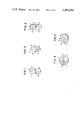
FIGS. 1-3 illustrate typical cross sections of the filaments of the present invention,
FIGS. 4 and 5 show cross sections of conventional conjugate filaments,
FIGS. 6-8 represent a series of lateral views of a short segment of the filaments of the present invention to show its physical behavior at different degrees of stretch,
FIGS. 9-11 represent similar lateral view of the conventional conjugate filaments, and
FIGS. 12 and 13 are rough sketches of the spinnerets used for spinning conjugate filaments of this invention.
DESCRIPTION OF THE PREFERRED EMBODIMENTS
The inventors of the present invention have conducted an intensive and extensive study on conjugate stretch yarns comprising thermoplastic elastomer and non-elastomeric polyamide or polyester in search of a structure of the conjugate stretch yarn in which stretchability resulting from crimp and rubber-like elasticity arising from elastomer are in best structural combination to produce the highest degree of stretchability. The study has resulted in the finding of a fact that a structure of the conjugate stretch yarn becomes most desirable when the filament is made to have a cross-sectional view of a compressed flat figure like a cocoon or an oval, in which the two components are conjugated together in such a way as to have their respective centroids on the major axis.
The present invention will be explained in detail referring to the accompanying drawings. In FIGS. 1 to 11, i indicates the centroid on the cross section of the filament; a, the length of the minor axis which passes the centroid i on the cross section of the filament; b, the length of the major axis which passes the centroid i on the cross section of the filament; E, the elastomer component; P, the non-elastomeric polyamide or polyester component; Ei, the centroid of the elastomer component on the cross section of the filament; and Pi, the centroid of the polyamide or polyester component on the cross section of the filament respectively.
The filament proposed in the present invention have a compressed flat figure like a cocoon or an oval in their cross section as shown in FIGS. 1-3. In setting up such form, the filament has two components conjugated to each other, i.e., a component E comprising thermoplastic elastomer and a component P comprising non-elastomeric polyamide or polyester, each having its centroid located on the major axis on its cross section. In other words, the two components are structurally conjugated together to hold the minor axis in common as their contact surface. When such a filament is made to develop crimp, it takes the form of a three-dimensional spiral crimp with the component E located inside the spiral and the component P outside the spiral as shown in FIG. 6. As the filament is being stretched, the component E is stretched straight, while the component P comes to take the form of a helical thread of a wood screw and surround the component E forming a certain angle and accordingly the filament itself exhibits a structure of a screw as shown in FIG. 7. The exhibition of such a structure is attributable to a fact that the centroid Ei of the elastomer component is far away from the centroid i on the cross section of the filament on the major axis and the component E can shrink much more than the component P because the component E has a greater value in terms of the physical construction of elastisity as well as the heat-shrinkage greater than the component P.
When the filament exhibiting the structure of a screw is further stretched, it can be stretched as far as it takes the form shown by 8.
Therefore, it may be said that at the stage in which the state of the filament shown in FIG. 6, shifts to the state of FIG. 7, the crimp stretchability is dominant; while at the stage in which the state of the filament shown in FIG. 7 shifts to the state of FIG. 8, the rubber-like elasticity is dominant.
The addition of this rubber-like elastic property to the conjugate filamentary yarn is a most remarkably characteristic of the present invention and this property can never be made available for conventional conjugate filamentary yarns in which each of the individual constituents presents a circular like those shown in FIGS. 4 and 5.
A conjugate stretch filament which has a cross section as shown in FIGS. 4 and 5 varies its shape in the order of FIGS. 9, 10 and 11 as the degree of stretch increases. A stretch filament of this type has the form of a three-dimensional spiral crimp with the component E located inside the spiral and the component P outside the spiral as shown in FIG. 9, quite similar to the one shown in FIG. 6.
When this crimped stretch filament is stretched, it directly takes the form shown in FIG. 10, without taking the form of a screw which can be realized by the conjugate stretch filament of the present invention in FIG. 7. Therefore, the filament can simply make use of crimp stretchability which is dominant only at the stage in which the state of the filament shown in FIG. 9, shifts to the state of FIG. 10. The filament accordingly can make no use of rubber-like elasticity which arises from its screw structure occurring at the stage in which the state of the filament shown in FIG. 9, shifts to the state of FIG. 11, in stepwise stretching.
Therefore, the crimped stretch yarn of high stretchability which can make the most of both stretchability arising from crimp and rubber-like elasticity resulting from elastomer should necessarily be a conjugate filamentary yarn in which each of the individual constituents takes the form of a screw structure shown in FIG. 7.
It is essential for a conjugate filament which takes the form of a screw structure to simultaneously satisfy both relationships of (a/b)≧1.2 and EiPi≧a/2, where a indicates the length of the minor axis which passes the centroid i on the cross section of the filament; b, the length of the major axis which passes the centroid i on the cross section of the filament; and EiPi, the distance between the centroid Ei of the elastomer component on the cross section of the filament and the centroid Pi of the non-elastomeric polyamide or polyester component respectively. When the centroid Ei of the elastomer component shifts too close to the centroid i on the cross section of the filament and results in (b/a)<1.2 and EiPi<(a/2), the shrinking point of the component E comprising elastomer comes too close to the centroid i on the cross section of the filament and accordingly enough shrinkage can not be caused to make the filament form a screw structure.
It will be easily understood that the efficient making of such a screw structure like the above can be achieved more satisfactorily when the contact surface between the E component of elastomer and the P component of polyamide or polyester is made small and also when the centroid Ei of the elastomer component is far away from the centroid Pi of polyamide or polyester component and centroid i on the cross section of the filament as shown in FIG. 1.
In the present invention it is essentially necessary for the filament to have the relation between a and b which satisfies a formula of 4≧(b/a)≧1.2 in order to have said screw structure and a cross section of a conjugate filament to be satisfactorily useful as clothing materials. When (b/a) is larger than 4, the cross section of the filament becomes too flat and when it is woven or knitted into a fabric, the fabric has rough harshness which makes the hand or feeling unsatisfactory. Also when the filament is made to form crimp, the resulting crimp coils are too large to make fine crimp and accordingly the stretchability of the obtained crimped stretch yarn is bad. On the other hand, when (b/a) is smaller than 1.2, the stretchability of the crimped filament becomes better but the crimp filament can not form a screw structure as mentioned before and rubber-like elasticity can not be utilized.
Furthermore, in the present invention it is necessary for the filament to have the relation between the area EA of component E on the cross section of the filament and the area PA of component P on the cross section of the filament which satisfies a formula of 2.3≧(EA/PA)≧0.43. When (EA/PA) is larger than 2.3, the elastomer component becomes too large to lower the color fastness and degrade the physical properties such as strength, elastic stretchability, etc. of the obtained crimped stretch yarn and the woven or knitted fabrics prepared from such crimped stretch yarn are unfit for use. When (EA/PA) is smaller than 0.43, the rubber-like elasticity becomes extremely small and a crimped stretch yarn having both crimp stretchability and rubber-like elasticity according to the present invention can not be obtained. It is most desirable to keep the value of (EA/PA) in the range of 0.67 to 1.5, usually it is to be set at 1.
Next, it is necessary in the present invention to keep the distance EiPi between Ei and Pi more than (a/2). More particularly, it means that the centroids Ei and Pi are substantially on the major axis b and that the distance EiPi between the two centroids is more than (a/2) which makes the cross section of the filament flat like a cocoon or an oval as shown in FIGS. 1-3 and also makes the centroids of the two components locate on the major axis. Conjugate filaments having such a circular cross section as shown in FIGS. 4 and 5 are not included in the range of claims laid by the present invention. When EiPi is smaller than (a/2), the stretability arising from crimp may be developed fully but the aforementioned screw structure can not be obtained. The filament will simply take the form of a crimped filament of conventionally known three-dimensional spiral structure which can make use of its non-elastomeric polymer's property only but no use of rubber-like elasticity of its elastomer component.
It is desirable to have the centroids Ei and Pi of the two components located on the major axis which passes the centroid i. However, Ei and Pi may be located somewhat off the major axis. In this case, an angle between the minor axis which passes i and the straight line iEi connecting Ei and i or the straight line iPi connecting Pi and i should desirably be kept within the range of 90°±30°.
The conjugation structure of a filament which has the form of a cross section of the filament like this is effected by conjugating a component E comprising elastomer and a component P comprising non-elastomeric polyamide or polyester in a side-by-side or eccentric sheath-core arrangement.
As thermoplastic elastomer to be used to form an elastic component in the present invention, it is recommendable to use elastomer which is melt spinnable, having a hardness of 90 to 100 when determined according to JIS K-6301. This type of thermoplastic elastomer includes elastomer of polyurethane type and elastomer of polyamide type. The former elastomer of polyurethane type is thermoplastic polyurethane which is obtained by reacting a mixture, which consists essentially of polyester having a terminal hydroxyl group and/or poly (oxyalkylene) glycol having a molecular weight of 1000 to 3000 diisocyanate, and glycol as chain-extending agent, and further addition of polycarbonate having a terminal hydroxyl group as case may be required. As the polyester mentioned above, dibasic acids such as sebacic acid and adipic acid, and diols such as ethylen glycol, butylene glycol, diethylene glycol, etc. are used. As the poly (oxyalkylene) glycol, such block copolymer or homogeneous polymer as poly(oxyethylene)glycol, poly(oxypropylene)glycol, poly(oxybutylene) glycol, etc. can be used. As diisocyanate, 2,4-tolylenediisocyanate, diphenylmethane-4,4'-diisocyanate, dicyclohexyl methane-4,4'-diisocyanate, etc. may be selected. As the chain-extending agent, ethylene glycol, propylene glycol, butylene glycol, and 1,4-β-hydroxyethoxybenzene can be used. As polycarbonate to be used optionally, a polymer of either bisphenol A and phosgen or bisphenol A and diphenylcarbonate having a terminal hydroxyl group must be used.
As the latter elastomer of polyamide type, a copolymer of polylauryl lactam and dicarboxylic acid of polybutylene glycol (produced from 1,4-butanediol) is generally used. The hardness can be controlled by adjusting the molecular weight of butylene glycol which composes the rubber ingredient or also by changing the copolymerization ratio between polylauryl lactam and rubber ingredient. As polyester which is one of the non-elastomeric components, polyethylene terephthalate, polybutylene terephthalate, polypropylene terephthalate, etc. which has generally the fiber-forming property may be mentioned, of which polyethylene terephthalate and polybutylene terephthalate may be counted as desirable polyester. A copolymer prepared by copolymerizing 5-sodium sulfoisophthalic acid with any of these polyesters is more desirable for the use, because it has good adhesion to elastomer. As polyamide which is another of the non-elastomeric components, nylon 6, nylon 66, nylon 610, nylon 11, nylon 12, nylon 13, etc. may be mentioned and among them, nylon 6 is especially recommendable. In determining the combination of an elastomeric component and a non-elastomeric component, care should be exercised in their selection, taking good compatibility and conjugating adhesiveness of the respective components into consideration so that the conjugated two components will not separate from each other during the stage of melt spinning, drawing, texturing, weaving, and knitting. Especially in case where polyester is used as a non-elastomeric component, it is recommendable to use elastomer of polyester type, for instance, a block copolymer of polyether and polyester as thermoplastic elastomer. Also it is desirable to use polyethylene terephthalate copolymerized with 5-sodium sulfoisophthalic acid as a polyester component since it improves the conjugating adhesiveness. On the other hand, in case where polyamide is used as a non-elastomeric component, it is desirable to use polyurethane of caprolactone type or polycarbonate type, or elastomer of polyamide type, for instance, a copolymer of polylauryl lactam and polyol, as thermoplastic elastomer.
A resistance-to-light improving agent, such as a compound of benzophenone or benzotriazole, or an inorganic manganese compound, or the like, may be added to elastomer and/or polyamide to improve their resistance to light.
By way of example, a method will be cited for obtaining the aforementioned crimped stretch yarn in which both stretchability arising from fine crimp and rubber-like elasticity of elastomer itself are utilized in a conjugate filamentary yarn, wherein the method comprises conjugate melt spinning thermoplastic elastomer and non-elastomeric polyamide or polyester in a side-by-side or eccentric sheath-core arrangement, followed by processes of drawing, heat treatment, and relaxted heat set treatment.
As the spinneret for conjugate melt spinning a filamentary yarn in a side-by-side arrangement in the abovementioned method, a spinneret like one shown in FIG. 12, which is designed to separately extrude the component E consisting of elastomer and the component P consisting of non-elastomeric polyamide or polyester from the respective spinneret holes and conjugate the two components at a point immediately after their extrusion from the spinneret, is recommendable as a proper spinneret. FIG. 12, is a sectional side view of such an example of spinneret. The component E and component P are respectively led to the conduits A and B and extruded from the spinning holes HE and HP. At this time, the aforementioned a/b can be put in a required balance by adjusting the distance l between the spinning holes HE and HP and the angle θ formed by these two spinning holes. When l is made larger and θ is made smaller, (b/a) becomes larger. In contrast with this, when l is made smaller and θ is made larger, (b/a) becomes smaller. In order to satisfy the condition of 4≧(b/a)≧1.2 stipulated by the present invention, necessary adjustment can be obtained when l is within the range of 0.3 mm to 0.1 mm and θ is 8° to 30°.
Furthermore, EA and PA can be put in a required balance by adjusting the extrusion rates of the component E and component P respectively by means of a gear pump (not shown in the drawing) equipped to the spinning machine. The area of the spinning holes HE and HP may be designed to meet the desired extrusion rates respectively. To give some reasonable criterion, the condition of 2.3≧EA/PA≧0.43 provided by the present invention can be satisfied when the linear velocity at the spinning hole is made to be within the range of 5 m/min. to 13 m/min.
The adjustment of EiPi varies deponding upon the other two conditions; however, in case where the spinning holes HE and HP are circular, when l is made larger, EiPi becomes larger and when θ is made smaller, EiPi also becomes larger as in the case of changing the conditions of (b/a). In another way, the adjustment of EiPi can also be effected by changing the shape of the spinning holes HE and HP. When HE and HP are made triangular and arranged at a distance l, EiPi becomes larger than when HE and HP are circular. Contrarily, when they are arranged as shown in FIG. 13, EiPi becomes smaller.
What we have mentioned with regard to FIGS. 12 and 13 in the above do not set any limitations to the present invention.
In case where the filament is conjugate melt spun in an eccentric sheath-core arrangement, a spinneret described in the gazette of Japanese Patent Publication No. 27175/80 is suited. The conjugate melt spinning in an eccentric sheath-core arrangement makes the elastomer component take its place in the core position and, therefore, is very effective in that it solves the problem of causing cohesion between the elastomer components at the time of take up which causes a difficulty in separating them into individual filaments as seen with the conjugate melt spinning of a filament in a side-by-side arrangement.
In order to make thus obtained conjugate yarn into a crimped stretch yarn in which both stretchability arising from fine crimp and elasticity of elastomer itself are made to be utilized, the desired crimped stretch yarn can be easily obtained by subjecting the conjugate yarn to the drawing, heat treatment followed by the relaxed heat set treatment conducted in the flow of heated fluid. It is desirable to make the crimped stretch yarn obtained after the relaxed heat set treatment show a shrinkage of 22% or less in a boiling-off water treatment. When the crimped stretch yarn shows a shrinkage in excess of 22%, it tends to have inferior weavability and knittability and the fabric prepared therefrom shows unsatisfactory dimensional stability. The shrinkage in the boiling-off water treatment tends to increase when the temperature of heat treatment after drawing is low or the temperature of heated fluid is low; however, it is perfectly possible to make the shrinkage 22% or less in the boiling-off water treatment when the treatment temperatures are kept within the range of heat treatment temperature after drawing and temperature of heated fluid as mentioned hereunder.
It is desirable to keep the temperature of heat treatment after drawing in range of a room temperature up to 120° C. When the temperature of said heat treatment is kept in excess of 120° C., the obtained crimped stretch yarn shows a shrinkage of 22% or less in the boiling-off water treatment. This improves the dimensional stability but reduces the degree of stretchability, thus tending to fail developing desired stretchability resulting from crimp. Incidentally, the drawing is desired to be conducted at ordinary operation temperature ranging from room temperature to 60° C.
It is desirable to keep the temperature of a heated fluid ejected into the jet nozzle within the range of 80° to 150° C. When the temperature of fluid is below 80° C., the shrinkage in the boiling-off water treatment increases, which tends to be undesirable in terms of dimensional stability. On the contrary, when the temperature exceeds 150° C., the shrinkage decreases but it tends to increase the elongation at break, which leads to "tight pick" in a fabric and also to lower the degree of stretchability, making the desired stretchability unobtainable. As the fluid to be used in this treatment, both air and steam are recommendable; however, air is more recommendable since it makes less noise.
As the heated fluid nozzle, nozzles which have hitherto been used for relaxed heat set treatment, such as those disclosed in the gazzete of Japanese Patent Publication No. 37576/70, gazzette of Japanese Utility Model Publication No. 9535/71, and specification of U.S. Pat. No. 4,188,691, can be used. A stretch yarn having fine uniform crimp can be obtained at a high speed by use of a fluid stuffing nozzle of this type.
It is desirable to have the relaxation percentage of 10% or more as a result of the relaxed heat set treatment conducted by use of a heated fluid nozzle, more desirably between 10% or more and 40% or less. The reason is that, the degree of stretchability varies greatly depending upon the relaxation percentage determined at the time of relaxed heat set treatment and therefore it is desirable to adjust the relaxation percentage within the abovementioned range in order to obtain a stretch yarn having the desired degree of stretchability (elastic stretchability). When the relaxation percentage obtained at this time is less than 10%, the degree of stretchability will be low and the resulting crimped stretch yarn will tend to the loss of desirable stretchability. The said relaxation percentage is determined by the following equation: ##EQU2##
As for the processes of drawing and heat treatment, any of so-called separate drawing methods in which spinning and drawing are conducted in independent processes and so-called spin-drawing methods in which spinning and drawing are conducted continuously can be followed. Also, so-called DTY method in which processes of drawing and relaxed heat set treatment are conducted continuously and so-called SDTY method in which all processes of spinning, drawing, and relaxed heat set treatment are conducted continuously can be followed. Any of these methods may be optionally adopted.
As explained in the above, the conjugate filamentary yarn of the present invention is composite spun from a component of thermoplastic elastomer and a component of polyamide or polyester arranged in a specific relationship, whereby both the stretchability arising from crimp and rubber-like elasticity are utilized to make an excellent crimped stretch conjugate yarn which shows high elastic recovery percentage of elongation and high degree of stretchability when highly elongated, which have never been seen with conventional stretch yarns. Therefore, it is very useful for the preparation of panty hose and other woven and knitted fabrics.
Incidentally, there occurres a reversal point rP regarding the direction with a component P as shown in FIG. 7, which the states of filament at a changing degree of stretch. However, this causes no trouble in actual use.
The present invention is described in detail by the following examples. The hardness of an elastomer component, elongation of crimp (EL) and rubber-like elasticity (RE), total crimp (TC) and shrinkage of boiling-off water treatment (FS), and elongation recovery (ER), used in the examples, were measured according to the following methods.
(1) Hardness:
According to JIS K-6301.
(2) Elongation of crimp (EL), rubber-like elasticity (RE):
A skein of a yarn, either drawn or relaxed by heat treatment after drawing, was weighted with an initial load of 2 mg/de, subjected to the crimping process in boiling water for 20 minutes, and dried naturally for 24 hours still under the initial load. The crimped yarn thus obtained was set on the tensile tester of Tensilon III type and the evaluation was made by inspecting the specimen with the use of a cathetometer of 20 magnifications. The test was started under the conditions: the length of the specimen, 20 cm; initial load, 2 mg/de; elongation speed, 100%/min., and chart speed, 20 cm/min., with the cathetometer focused on the 10-cm middle part of the specimen. During the inspection, a state of the specimen shown in FIG. 7, was observed at the initial stage, and the crimp was gradually stretched and soon reached a state as shown in FIG. 8. A mark was put to indicate how far the specimen was elongated. The elongation obtained so far was the elongation arising from crimp. When further stretched, the specimen reached a state as shown in FIG. 9. The stretch between FIG. 8 and FIG. 9, was rubber-like elasticity. The result of the determination was obtained from the average value of 5 measurements.
(3) Total crimp (TC) and shrinkage of boiling-off water treatment (FS):
A skein was prepared from a yarn which has been subjected to a relaxed heat set treatment and weighted with an initial load of 2 mg/de and the length (l0) of the skein was measured. Without removing the initial load, the yarn was subjected to a crimping treatment for 20 minutes in boiling water and dried naturally of 24 hours under the load. The load was increased to a total of 200 mg/de and 1 minute later the length (l1) of the skein was measured. Then the load was removed and the skein was weighted again with the initial load. 1 minute later the length (l2) was measured. Total crimp (TC) and shrinkage of boiling-off water treatment (FS) were calculated by the following equations respectively. ##EQU3## (4) Elongation recovery (ER):
A skein was prepared from a yarn which had been subjected to a heat treatment, weighted with an initial load of 2 mg/de, subjected to a crimping process for 20 minutes in boiling water, and dried naturally for 24 hours without removing the initial load. The elongation recovery (ER) was determined with thus prepared specimen under temperature of 20°±2° C. and relative humidity of 65±2% by hanging the yarn as follows:
(a) Length of specimen yarn: 200 mm (length l0 of yarn under initial load)
(b) Initial load: 2 mg/de
(c) Test load: 1000 mg/de
(d) Time under load: 3 minutes
(e) Measurement of yarn length l1 under test load, removal of test load and weighting of yarn with initial load.
(f) Residual length l2 of yarn was measured when 3 minutes had passed after initial load was placed.
(g) Elongation recovery was calculated according to the following equation: ##EQU4##
EXAMPLE 1
Nylon 6 having the intrinsic viscosity [η] of 1.1 and commercially available thermoplastic polyurethane Elastollan E595 (capro type) having the hardness of 95 (manufactured by Nippon Elastollan Co., Ltd) which was to make an elastomer component were melted separately at 247° C. and 228° C. and conjugate melt spun with the use of a spinneret of side-by-side type as shown in FIG. 12, or spinneret of eccentric sheath-core type as described in the gazette of Japanese Patent Publication No. 27175/80, heated at 240° C. The area ratio EA/PA between the elastomer component and polyamide component on the cross section of the conjugate filament was varied by adjusting the extrusion ratio between the two component by means of the respective gear pumps. Also (b/a) and EiPi were varied by changing HE, HP, l and θ of the spinneret shown in FIG. 12. The conjugate yarn was taken up as undrawn yarn at the take up speed of 500 m/min. while applying 0.6% of silicone oil. After that the yarn was drawn separately in a drawing process and made to have elongation at break of 30% to 40%. The elongation of crimp (EL) and rubber-like elasticity of the drawn yarn were determined and the results are shown in Table 1, Nos. 2-9, No. 11 and Nos. 13-14.
The same determination was conducted with conjugate filament having a structure as shown in FIG. 4, prepared by use of a spinneret of side-by-side type described in the gazette of Japanese Patent Publication No. 20247/68 and the result is also shown in Table 1, No. 1.
Furthermore, the result obtained with a conjugate filamentary yarn prepared from an elastomer component comprising commercially available Elastomer Diamide×3978 of polyamide type having the hardness of 97 manufactured by Daicel Chemical Industries Ltd and another component comprising polyethylene terephthalate, [η] 0.65, modified with 2.7 mole % of 5-sodium sulfoisophthalate under the conditions of Table 1, No. 3 is shown in No. 10 of the same table and another result obtained with a conjugate filamentary yarn prepared from an elastomer component comprising said Elastomer Diamide×3978 of polyamide type and another component comprising polybutylene terephthalate, [η] 0.87, modified with 2.1 mole % of 5-sodium sulfoisophthalate under the conditions of Table 1, No. 3 is shown in No. 12.
              TABLE 1                                                     
______________________________________                                    
Run No.                                                                   
      Cross section of a filament                                         
                  ##STR1##                                                
                         EA/PA                                            
                                ##STR2##                                  
                                     EL (%)                               
                                           RE (%)                         
______________________________________                                    
*1    FIG. 2, (a)                                                         
                 1      1      0.7a  69     4                             
*2    FIG. 1, (a)                                                         
                 1.1    1      0.7a  71     5                             
 3    FIG. 1, (a)                                                         
                 1.4    1      0.6a  73    28                             
 4    FIG. 1, (a)                                                         
                 3.8    1      1.6a  25    29                             
*5    FIG. 1, (a)                                                         
                 4.2    1      2.1a   7    16                             
 6    FIG. 1, (a)                                                         
                 1.6    2.2    1.2a  83    46                             
 7    FIG. 1, (a)                                                         
                 1.5    0.45   1.3a  64    33                             
*8    FIG. 1, (a)                                                         
                 1.4    0.40   1.1a  31     3                             
*9    FIG. 1, (a)                                                         
                 1.3    1      0.4a  83     3                             
 10   FIG. 1, (a)                                                         
                 1.5    1      0.7a  65    24                             
*11   FIG. 1, (a)                                                         
                 1.7    2.5    1.1a  49     7                             
 12   FIG. 1, (a)                                                         
                 1.5    1      0.7a  59    22                             
 13   FIG. 1, (c)                                                         
                 1.4    1      0.6a  66    25                             
 14   FIG. 1, (b)                                                         
                 1.5    1      0.6a  70    26                             
______________________________________                                    
 *Comparison                                                              
The specimens which satisfied the conditions specified by the present invention had both elongation of crimp (EL) and rubber-like elasticity (RE) of 20% or more and showed an excellent stretchability but those other than the present invention especially showed a smaller rubber-like elasticity and failed to show a powerful stretchability.
EXAMPLE 2
Nylon 6 having the intrinsic viscosity [η] of 1.1 (determined by use of m-cresol solution at 30° C.) and a polyurethane component comprising commercially available thermoplastic polyurethane Elastollan E595 (capro type) having the hardness of 95 and another polyurethane component comprising Elastollan E995 (carbonate type) having the hardness of 95 (both manufactured by Nippon Elastollan Co., Ltd.) were used to prepare respective conjugate filamentary yarns. Nylon 6 was melted at 247° C., polyurethane E595 at 228° C., and E995 at 230° C. separately and were made into two kinds of conjugate filamentary yarns respectively with the use of a spinneret of side-by-side type heated at 245° C. as shown in FIG. 12. The area ratio EA/PA between the polyurethane component and the polyamide component was made to 1 by adjusting the respective extrusion ratios between the components. The cross section of the respective filaments was made to take the shape of FIG. 1, and a/b was made to be 1.5 by adjusting l and θ of the spinneret of FIG. 12. 0.6% by weight of silicone oil was applied to the obtained melt spun yarns and undrawn yarns of 700 denier/12 filaments were obtained.
Thus obtained undrawn yarn was once taken up and was then subjected to the DTY process, wherein drawing and relaxed heat set treatment were combined in continuance, or the yarn was, without being taken up, directly subjected to the SDTY process where spinning was followed by drawing and relaxed heat set treatment, to be put to the test. The drawing is so conducted as to give an elongation at break of 25 to 35% to the drawn yarn. After having been heat treated at varied temperature, the yarn was led to the heated compressed air nozzle as described in FIG. 1 of the specification of U.S. Pat. No. 4,188,691, wherein temperature of the compressed air and relaxation rate were varied under the constant pressure of the compressed air kept at 1.0 kg/cm2 G. In Table 2, the conditions of drawing and texturing, and physical properties of the obtained crimped stretch yarns are shown.
The results of the test conducted for the filament prepared to have a structure of FIG. 4, by use of an ordinary spinneret of side-by-side type described in the gazette of Japanese Patent Publication No. 20247/68, are also shown in Table 2.
                                  TABLE 2                                 
__________________________________________________________________________
Spinning and drawing conditions      Texturing conditions                 
Cross    Kind       Spin-                                                 
                         Draw-                                            
                              Heat treating                               
                                     Temperature                          
section  of         ning ing  temperature                                 
                                     of heated                            
                                            Relax-                        
                                                Properties of crimped     
                                                yarns                     
Run                                                                       
   of a  poly-                                                            
              Texturing                                                   
                    speed                                                 
                         speed                                            
                              after draw-                                 
                                     compressed                           
                                            ation                         
                                                TC FS EL RE ER            
No.                                                                       
   filament                                                               
         urethane                                                         
              method                                                      
                    (m/min.)                                              
                         (m/min.)                                         
                              ing (°C.)                            
                                     air (°C.)                     
                                            (%) (%)                       
                                                   (%)                    
                                                      (%)                 
                                                         (%)              
                                                            (%)           
__________________________________________________________________________
15 FIG. 1, (a)                                                            
         E595 DTY   500  1000 Room    80    30  40 19 118                 
                                                         52 86            
                              temperature                                 
16 "     E995 "     "    "    Room   100    "   43 21 125                 
                                                         80 89            
                              temperature                                 
17 "     "    "     "    "     80    "      "   41 20 102                 
                                                         58 88            
18 "     "    "     "    "    120    "      "   37 17  85                 
                                                         37 84            
19 "     "    "     "    "    130    "      "   33 15  65                 
                                                         20 80            
20 "     "    "     "    "    Room    60    "   44 25 112                 
                                                         75 88            
                              temperature                                 
21 "     "    SDTY  "    2000 Room    80    "   43 22 125                 
                                                         75 88            
                              temperature                                 
22 "     "    "     "    "    Room   100    "   43 21 125                 
                                                         80 89            
                              temperature                                 
23 "     "    "     "    "    Room   150    "   41 18  85                 
                                                         35 84            
                              temperature                                 
24 "     "    DTY   "    1000 Room   160    "   39 16  70                 
                                                         20 79            
                              temperature                                 
25 "     "    "     "    "    Room   100     5  34 19  74                 
                                                         24 80            
                              temperature                                 
26 "     "    "     "    "    Room   "      10  36 20 90 40 83            
                              temperature                                 
27 "     "    "     "    "    Room   "      20  40 21 106                 
                                                         60 86            
                              temperature                                 
*28                                                                       
   FIG. 2, (a)                                                            
         "    "     "    "    Room   "      30  37 18 125                 
                                                          6 67            
                              temperature                                 
__________________________________________________________________________
 *Comparison                                                              
As seen from Table 2, those specimens in Nos. 15 to 18, 21 to 23, 26 and 27, wherein the optimum conditions mentioned before were statisfied, showed the elongation of crimp (EL) of 85 to 125% and rubber-like elasticity (RE) of 35 to 80%, making a considerably great total of 120 to 200%. The elongation recovery (ER) under load of 1.0 g/de was more than 80%, showing excellent stretchability and recoverableness to provide stretch yarns which would not raise any problem as to the dimensional stability. In contrast to the preceding specimens, Nos. 19 and 24 where the temperature of post-drawing heat treatment was beyond the range of room temperature and 120° C. or the temperature of heated compressed air was beyond the range of 80° and 150° C. and No. 25 where the relaxation percentage was less than 10%, showed a good shrinkage of boiling-off water treatment (FS) but the elongation of crimp (EL) and rubber-like elasticity (RE) were both low and the elongation recovery (ER) was below 80%.
No. 20, in which the temperature of heated compressed air was low, showed a good elongation of crimp (EL) and rubber-like elasticity (RE) but the obtained stretch yarn tended to show unsatisfactory dimensional stability because of its high shrinkage of boiling-off water treatment reading 25%.
Further, a conjugate stretch filament of No. 28, which was prepared in a side-by-side arrangement whose cross section was formed like FIG. 4, failed to exhibit a satisfactory screw structure when it was stretched. The yarn accordingly had only a slight degree of rubber-like elasticity and did not have powerful stretchability.

Claims (12)

I claim:
1. A conjugate filamentary yarn, characterized in that each of the individual constituents whose cross-sectional view presents a compressed flat figure, which comprises an elastomeric thermoplastic elastomer and a non-elastomeric polyamide or a polyester, wherein the respective components are arranged in such a way as to satisfy the following formulas (I) to (III) simultaneously: ##EQU5## where a indicates the length of the minor axis which passes the centroid on the cross section of the filament; b, the length of the major axis which passes the centroid on the cross section of the filament; EA, the area occupied by the thermoplastic elastomer on the cross section of the filament; PA, the area occupied by non-elastomeric polyamide or polyester on the cross section of the filament; and EiPi, the distance between the centroid Ei of the thermoplastic elastomer component on the cross section of the filament and the centroid Pi of the non-elastomeric polyamide or polyester component.
2. A conjugate filamentary yarn according to claim 1, wherein the cross section of the filament takes the shape of a cocoon.
3. A conjugate filamentary yarn according to claim 1, wherein the cross section of the filament takes the shape of an oval.
4. A conjugate filamentary yarn according to claim 1, wherin the centroid of said thermoplastic elastomer (Ei) and the centroid of said non-elastomeric polyamide or polyester (Pi) are located on the major axis which passes the centroid i on the cross section of the filament.
5. A conjugate filamentary yarn according to claim 1, wherein said filament is prepared in a side-by-side arrangement.
6. A conjugate filamentary yarn according to claim 1, wherein said filament is prepared in an eccentric sheath-core arrangement.
7. A conjugate filamentary yarn according to claim 1, wherein the hardness of said thermoplastic elastomer (measured according to JIS K-6301) is within the range of 90 to 100.
8. A conjugate filamentary yarn according to claim 1, wherein said thermoplastic elastomer is elastomer of the polyurethane type.
9. A conjugate filamentary yarn according to claim 1, wherein said thermoplastic elastomer is elastomer of the polyamide type.
10. A conjugate filamentary yarn according to claim 1, wherein said non-elastomeric polyamide is nylon 6.
11. A conjugate filamentary yarn according to claim 1, wherein said non-elastomeric polyester is polyethylene terephthalate or polybutylene terephthalate.
12. A conjugate filamentary yarn according to claim 11, wherein said non-elastomeric polyester is a polyester which is copolymerized with 5-sodium isophthalic acid.
US06/385,942 1981-06-05 1982-06-07 Crimpable conjugate filamentary yarns having a flattened cross-sectional configuration Expired - Fee Related US4405686A (en)

Applications Claiming Priority (2)

Application Number Priority Date Filing Date Title
JP56085611A JPS57205520A (en) 1981-06-05 1981-06-05 Conjugate fiber
JP56-85611 1981-06-05

Publications (1)

Publication Number Publication Date
US4405686A true US4405686A (en) 1983-09-20

Family

ID=13863626

Family Applications (1)

Application Number Title Priority Date Filing Date
US06/385,942 Expired - Fee Related US4405686A (en) 1981-06-05 1982-06-07 Crimpable conjugate filamentary yarns having a flattened cross-sectional configuration

Country Status (4)

Country Link
US (1) US4405686A (en)
EP (1) EP0068659B1 (en)
JP (1) JPS57205520A (en)
DE (1) DE3269597D1 (en)

Cited By (34)

* Cited by examiner, † Cited by third party
Publication number Priority date Publication date Assignee Title
US4546043A (en) * 1984-01-18 1985-10-08 Teijin Limited Hollow irregular multifilament yarn and process and spinneret for producing the same
US4753834A (en) * 1985-10-07 1988-06-28 Kimberly-Clark Corporation Nonwoven web with improved softness
US5102603A (en) * 1989-07-03 1992-04-07 The Goodyear Tire & Rubber Company Process for manufacturing polyethylene terephthalate industrial yarn
US5200248A (en) * 1990-02-20 1993-04-06 The Procter & Gamble Company Open capillary channel structures, improved process for making capillary channel structures, and extrusion die for use therein
US5199253A (en) * 1990-07-16 1993-04-06 American Manufacturing Company, Inc. Nylon rope having superior friction and wearing resistance
US5242644A (en) * 1990-02-20 1993-09-07 The Procter & Gamble Company Process for making capillary channel structures and extrusion die for use therein
US5368926A (en) * 1992-09-10 1994-11-29 The Procter & Gamble Company Fluid accepting, transporting, and retaining structure
US5489382A (en) * 1987-10-29 1996-02-06 Terumo Kabushiki Kaisha Oxygenator using porous hollow fiber membrane
US5628736A (en) * 1994-04-29 1997-05-13 The Procter & Gamble Company Resilient fluid transporting network for use in absorbent articles
US5652057A (en) * 1995-03-31 1997-07-29 Hoechst Trevira Gmbh & Co. Kg High strength core-sheath monofilaments for technical applications
WO1997049848A1 (en) * 1996-06-27 1997-12-31 Kimberly-Clark Worldwide, Inc. Self-crimping conjugate filament and seamless band formed therefrom and method of making same
US5972502A (en) * 1998-03-04 1999-10-26 Optimer, Inc. Self-crimping fibers and methods for their preparation
US6225243B1 (en) 1998-08-03 2001-05-01 Bba Nonwovens Simpsonville, Inc. Elastic nonwoven fabric prepared from bi-component filaments
WO2001053573A1 (en) * 2000-01-20 2001-07-26 E.I. Du Pont De Nemours And Company Method for high-speed spinning of bicomponent fibers
US6454989B1 (en) 1998-11-12 2002-09-24 Kimberly-Clark Worldwide, Inc. Process of making a crimped multicomponent fiber web
US20030171052A1 (en) * 2001-09-28 2003-09-11 Vishal Bansal Stretchable nonwoven web and method therefor
US6677038B1 (en) 2002-08-30 2004-01-13 Kimberly-Clark Worldwide, Inc. 3-dimensional fiber and a web made therefrom
US6692687B2 (en) 2000-01-20 2004-02-17 E. I. Du Pont De Nemours And Company Method for high-speed spinning of bicomponent fibers
US20040041307A1 (en) * 2002-08-30 2004-03-04 Kimberly-Clark Worldwide, Inc. Method of forming a 3-dimensional fiber into a web
US20040041308A1 (en) * 2002-08-30 2004-03-04 Kimberly-Clark Worldwide, Inc. Method of making a web which is extensible in at least one direction
US6838402B2 (en) * 1999-09-21 2005-01-04 Fiber Innovation Technology, Inc. Splittable multicomponent elastomeric fibers
US20050124245A1 (en) * 2003-12-03 2005-06-09 Tianyi Liao Size-covered composite yarns and method for making same
US20060147716A1 (en) * 2004-12-30 2006-07-06 Jaime Braverman Elastic films with reduced roll blocking capability, methods of making same, and limited use or disposable product applications incorporating same
US7220478B2 (en) 2003-08-22 2007-05-22 Kimberly-Clark Worldwide, Inc. Microporous breathable elastic films, methods of making same, and limited use or disposable product applications
US7226880B2 (en) 2002-12-31 2007-06-05 Kimberly-Clark Worldwide, Inc. Breathable, extensible films made with two-component single resins
US7270723B2 (en) 2003-11-07 2007-09-18 Kimberly-Clark Worldwide, Inc. Microporous breathable elastic film laminates, methods of making same, and limited use or disposable product applications
US20100318012A1 (en) * 2009-06-16 2010-12-16 Arkema France Bacteriostatic textile based on polyamide 11
US7932196B2 (en) 2003-08-22 2011-04-26 Kimberly-Clark Worldwide, Inc. Microporous stretch thinned film/nonwoven laminates and limited use or disposable product applications
KR101155454B1 (en) * 2011-11-11 2012-06-15 (주)보광 Process Of Producing Nylon 6 Draw?Textured?Yarn With High Elasticity
JP2013253348A (en) * 2012-06-08 2013-12-19 Nippon Ester Co Ltd Latently crimpable conjugate fiber
CN103882538A (en) * 2013-12-04 2014-06-25 太仓荣文合成纤维有限公司 Novel elastic fiber and preparation method thereof
US20210062378A1 (en) * 2019-09-03 2021-03-04 Berry Global, Inc. Hydroentangled Nonwoven Fabrics Including Crimped Continuous Fibers
US11001946B2 (en) * 2018-08-10 2021-05-11 GM Global Technology Operations LLC Knitted durable fabrics for use on vehicle seats
CN113174654A (en) * 2021-05-26 2021-07-27 四川大学 Polyamide side-by-side composite elastic fiber and preparation method thereof

Families Citing this family (13)

* Cited by examiner, † Cited by third party
Publication number Priority date Publication date Assignee Title
US4439487A (en) * 1982-12-17 1984-03-27 E. I. Du Pont De Nemours & Company Polyester/nylon bicomponent flament
JPS59223337A (en) * 1983-06-02 1984-12-15 株式会社クラレ Fabric having velvet-like appearance
JPS6221820A (en) * 1985-07-16 1987-01-30 Kuraray Co Ltd Polyurethane based multicomponent fiber
JPS62170509A (en) * 1986-01-20 1987-07-27 Teijin Ltd Stretchable synthetic filament yarn and production thereof
DE68926186T2 (en) * 1988-06-30 1996-10-24 Toray Industries Self-crimping composite fiber containing polyurethane and polyamide
CN1058813A (en) * 1990-04-27 1992-02-19 钟纺株式会社 Elastic core and sheath type bicomponent filament yarn and contain the fabric construction of this bicomponent filament yarn
JP2892262B2 (en) * 1993-11-02 1999-05-17 バンドー化学株式会社 Belt for transporting paper sheets
JP2002363828A (en) * 2001-06-06 2002-12-18 Toray Ind Inc Side by side conjugated fiber and method of producing the same
US20040110442A1 (en) * 2002-08-30 2004-06-10 Hannong Rhim Stretchable nonwoven materials with controlled retraction force and methods of making same
FR2902114B1 (en) * 2006-06-12 2009-02-06 Promiles Snc POLYMERIC FILAMENT HAVING AT LEAST ONE LONGITUDINAL ETOFFE CHANNEL COMPRISING THESE FILAMENTS, ARTICLE FORMED THEREFROM, AND METHOD OF MAKING SAID FILAMENT
JP5041836B2 (en) * 2007-03-20 2012-10-03 グンゼ株式会社 Method for producing conjugate fiber
US9869040B2 (en) * 2008-10-17 2018-01-16 INVISTA North america S.a.r.1. Bicomponent spandex
EP3603432A4 (en) * 2017-03-30 2020-12-16 Kaneka Corporation Core-sheath composite fiber for artificial hair and headdress product comprising same

Citations (10)

* Cited by examiner, † Cited by third party
Publication number Priority date Publication date Assignee Title
US2932079A (en) * 1956-03-08 1960-04-12 Schiesser Ag Trikotfabriken Complex artificial filaments
US3109220A (en) * 1960-08-19 1963-11-05 Du Pont Tetralobal cross-sectioned filaments
US3117906A (en) * 1961-06-20 1964-01-14 Du Pont Composite filament
US3156607A (en) * 1961-05-31 1964-11-10 Du Pont Lobed filament
US3547763A (en) * 1967-06-05 1970-12-15 Du Pont Bicomponent acrylic fiber having modified helical crimp
US3914488A (en) * 1973-09-24 1975-10-21 Du Pont Polyester filaments for fur-like fabrics
US4002795A (en) * 1974-03-25 1977-01-11 Rhone-Poulenc-Textile Crimped yarns and method for making them
US4106313A (en) * 1968-11-06 1978-08-15 Monsanto Company Sheer stretch hose having high compressive force uniformity, and yarn
US4118534A (en) * 1977-05-11 1978-10-03 E. I. Du Pont De Nemours And Company Crimped bicomponent-filament yarn with randomly reversing helical filament twist
US4248934A (en) * 1977-07-07 1981-02-03 Bayer Aktiengesellschaft Fibre and filament mixtures containing high-shrinkage bifilar poly(mod)acrylic filaments or fibres modified with carbon black

Family Cites Families (6)

* Cited by examiner, † Cited by third party
Publication number Priority date Publication date Assignee Title
US3315021A (en) * 1964-06-19 1967-04-18 Snia Viscosa Process for the production of crimpable composite synthetic yarns
GB1151272A (en) * 1967-02-28 1969-05-07 Kanegafuchi Spinning Co Ltd A Method of Producing Conjugate Fibres having and Improved Lustre
GB1294723A (en) * 1969-02-28 1972-11-01 Asahi Chemical Ind Conjugate fibres
JPS4936915A (en) * 1972-08-22 1974-04-05
GB1518500A (en) * 1975-10-24 1978-07-19 Courtaulds Ltd Bicomponent filaments
JPS54138619A (en) * 1978-04-17 1979-10-27 Toray Ind Inc Polyurethane eccentric sheath-core composite fibers

Patent Citations (10)

* Cited by examiner, † Cited by third party
Publication number Priority date Publication date Assignee Title
US2932079A (en) * 1956-03-08 1960-04-12 Schiesser Ag Trikotfabriken Complex artificial filaments
US3109220A (en) * 1960-08-19 1963-11-05 Du Pont Tetralobal cross-sectioned filaments
US3156607A (en) * 1961-05-31 1964-11-10 Du Pont Lobed filament
US3117906A (en) * 1961-06-20 1964-01-14 Du Pont Composite filament
US3547763A (en) * 1967-06-05 1970-12-15 Du Pont Bicomponent acrylic fiber having modified helical crimp
US4106313A (en) * 1968-11-06 1978-08-15 Monsanto Company Sheer stretch hose having high compressive force uniformity, and yarn
US3914488A (en) * 1973-09-24 1975-10-21 Du Pont Polyester filaments for fur-like fabrics
US4002795A (en) * 1974-03-25 1977-01-11 Rhone-Poulenc-Textile Crimped yarns and method for making them
US4118534A (en) * 1977-05-11 1978-10-03 E. I. Du Pont De Nemours And Company Crimped bicomponent-filament yarn with randomly reversing helical filament twist
US4248934A (en) * 1977-07-07 1981-02-03 Bayer Aktiengesellschaft Fibre and filament mixtures containing high-shrinkage bifilar poly(mod)acrylic filaments or fibres modified with carbon black

Cited By (40)

* Cited by examiner, † Cited by third party
Publication number Priority date Publication date Assignee Title
US4546043A (en) * 1984-01-18 1985-10-08 Teijin Limited Hollow irregular multifilament yarn and process and spinneret for producing the same
US4753834A (en) * 1985-10-07 1988-06-28 Kimberly-Clark Corporation Nonwoven web with improved softness
US5489382A (en) * 1987-10-29 1996-02-06 Terumo Kabushiki Kaisha Oxygenator using porous hollow fiber membrane
US5102603A (en) * 1989-07-03 1992-04-07 The Goodyear Tire & Rubber Company Process for manufacturing polyethylene terephthalate industrial yarn
US5200248A (en) * 1990-02-20 1993-04-06 The Procter & Gamble Company Open capillary channel structures, improved process for making capillary channel structures, and extrusion die for use therein
US5242644A (en) * 1990-02-20 1993-09-07 The Procter & Gamble Company Process for making capillary channel structures and extrusion die for use therein
US5199253A (en) * 1990-07-16 1993-04-06 American Manufacturing Company, Inc. Nylon rope having superior friction and wearing resistance
US5333442A (en) * 1990-07-16 1994-08-02 American Manufacturing Company, Inc. Method for producing a rope having superior friction and wearing resistance
US5368926A (en) * 1992-09-10 1994-11-29 The Procter & Gamble Company Fluid accepting, transporting, and retaining structure
US5628736A (en) * 1994-04-29 1997-05-13 The Procter & Gamble Company Resilient fluid transporting network for use in absorbent articles
US5652057A (en) * 1995-03-31 1997-07-29 Hoechst Trevira Gmbh & Co. Kg High strength core-sheath monofilaments for technical applications
WO1997049848A1 (en) * 1996-06-27 1997-12-31 Kimberly-Clark Worldwide, Inc. Self-crimping conjugate filament and seamless band formed therefrom and method of making same
US5972502A (en) * 1998-03-04 1999-10-26 Optimer, Inc. Self-crimping fibers and methods for their preparation
US6225243B1 (en) 1998-08-03 2001-05-01 Bba Nonwovens Simpsonville, Inc. Elastic nonwoven fabric prepared from bi-component filaments
US6454989B1 (en) 1998-11-12 2002-09-24 Kimberly-Clark Worldwide, Inc. Process of making a crimped multicomponent fiber web
US6838402B2 (en) * 1999-09-21 2005-01-04 Fiber Innovation Technology, Inc. Splittable multicomponent elastomeric fibers
WO2001053573A1 (en) * 2000-01-20 2001-07-26 E.I. Du Pont De Nemours And Company Method for high-speed spinning of bicomponent fibers
US6692687B2 (en) 2000-01-20 2004-02-17 E. I. Du Pont De Nemours And Company Method for high-speed spinning of bicomponent fibers
CN100453714C (en) * 2000-01-20 2009-01-21 因维斯塔技术有限公司 Method for high-speed spinning of bicomponent fibers
US20030171052A1 (en) * 2001-09-28 2003-09-11 Vishal Bansal Stretchable nonwoven web and method therefor
US8093161B2 (en) 2001-09-28 2012-01-10 Invista North America S.àr.l. Stretchable nonwoven web and method therefor
US20040041308A1 (en) * 2002-08-30 2004-03-04 Kimberly-Clark Worldwide, Inc. Method of making a web which is extensible in at least one direction
US6677038B1 (en) 2002-08-30 2004-01-13 Kimberly-Clark Worldwide, Inc. 3-dimensional fiber and a web made therefrom
US6896843B2 (en) 2002-08-30 2005-05-24 Kimberly-Clark Worldwide, Inc. Method of making a web which is extensible in at least one direction
US20040041307A1 (en) * 2002-08-30 2004-03-04 Kimberly-Clark Worldwide, Inc. Method of forming a 3-dimensional fiber into a web
US6881375B2 (en) 2002-08-30 2005-04-19 Kimberly-Clark Worldwide, Inc. Method of forming a 3-dimensional fiber into a web
US7226880B2 (en) 2002-12-31 2007-06-05 Kimberly-Clark Worldwide, Inc. Breathable, extensible films made with two-component single resins
US7220478B2 (en) 2003-08-22 2007-05-22 Kimberly-Clark Worldwide, Inc. Microporous breathable elastic films, methods of making same, and limited use or disposable product applications
US7932196B2 (en) 2003-08-22 2011-04-26 Kimberly-Clark Worldwide, Inc. Microporous stretch thinned film/nonwoven laminates and limited use or disposable product applications
US7270723B2 (en) 2003-11-07 2007-09-18 Kimberly-Clark Worldwide, Inc. Microporous breathable elastic film laminates, methods of making same, and limited use or disposable product applications
US20050124245A1 (en) * 2003-12-03 2005-06-09 Tianyi Liao Size-covered composite yarns and method for making same
US20060147716A1 (en) * 2004-12-30 2006-07-06 Jaime Braverman Elastic films with reduced roll blocking capability, methods of making same, and limited use or disposable product applications incorporating same
US20100318012A1 (en) * 2009-06-16 2010-12-16 Arkema France Bacteriostatic textile based on polyamide 11
US20140346703A1 (en) * 2009-06-16 2014-11-27 Arkema France Bacteriostatic textile based on polyamide 11
KR101155454B1 (en) * 2011-11-11 2012-06-15 (주)보광 Process Of Producing Nylon 6 Draw?Textured?Yarn With High Elasticity
JP2013253348A (en) * 2012-06-08 2013-12-19 Nippon Ester Co Ltd Latently crimpable conjugate fiber
CN103882538A (en) * 2013-12-04 2014-06-25 太仓荣文合成纤维有限公司 Novel elastic fiber and preparation method thereof
US11001946B2 (en) * 2018-08-10 2021-05-11 GM Global Technology Operations LLC Knitted durable fabrics for use on vehicle seats
US20210062378A1 (en) * 2019-09-03 2021-03-04 Berry Global, Inc. Hydroentangled Nonwoven Fabrics Including Crimped Continuous Fibers
CN113174654A (en) * 2021-05-26 2021-07-27 四川大学 Polyamide side-by-side composite elastic fiber and preparation method thereof

Also Published As

Publication number Publication date
DE3269597D1 (en) 1986-04-10
JPS57205520A (en) 1982-12-16
EP0068659A1 (en) 1983-01-05
JPH0141723B2 (en) 1989-09-07
EP0068659B1 (en) 1986-03-05

Similar Documents

Publication Publication Date Title
US4405686A (en) Crimpable conjugate filamentary yarns having a flattened cross-sectional configuration
JP5160679B2 (en) Composite effect yarn and its fabric
US3968307A (en) Mixed filaments
US6548166B2 (en) Stretchable fibers of polymers, spinnerets useful to form the fibers, and articles produced therefrom
US5308697A (en) Potentially elastic conjugate fiber, production thereof, and production of fibrous structure with elasticity in expansion and contraction
US6783853B2 (en) Hetero-composite yarn, fabrics thereof and methods of making
JPH0236683B2 (en)
EP0430227A2 (en) Elastic synthetic polymer filament with multi-lobated cross-sectional profile
EP1320638B1 (en) Stretchable polymeric fibers and articles produced therefrom
EP1322802B1 (en) Stretchable fibers of polymers, spinnerets useful to form the fibers, and articles produced therefrom
JP3473890B2 (en) Polyester composite fiber
JP2000328382A (en) Elastic spun yarn
JP3140728B2 (en) Cationic dyeable latent crimpable polyester composite fiber and method for producing the same
JPS6134220A (en) Composite yarn
JPH0814042B2 (en) Method for producing splittable conjugate fiber and mixed yarn thereof
JPS6141323A (en) Hollow composite yarn
JPH073554A (en) Production of false-twisted hollow polyester yarn
US20020155290A1 (en) Stretchable polymeric fibers and articles produced therefrom
JP3863286B2 (en) Polyester special crimped yarn and method for producing the same
US3817823A (en) Crimpable composite polycarbonamide filament
JPS62149927A (en) Different finness blended fiber yarn
JP2002030526A (en) Highly crimped conjugate fiber
JP2000248429A (en) Polyester conjugate fiber for stretching woven and knitted fabric
JPS6336382B2 (en)
JPH0299613A (en) Production of conjugated fiber

Legal Events

Date Code Title Description
AS Assignment

Owner name: TEIJIN LIMITED, 11, MINAMIHONMACHI 1-CHOME, HIGASH

Free format text: ASSIGNMENT OF ASSIGNORS INTEREST.;ASSIGNORS:KURODA, TOSHIMASA;ISHII, SEIJI;SHIBATA, TATSUYA;REEL/FRAME:004131/0218

Effective date: 19820512

Owner name: TEIJIN LIMITED, 11, MINAMIHONMACHI 1-CHOME, HIGASH

Free format text: ASSIGNMENT OF ASSIGNORS INTEREST;ASSIGNORS:KURODA, TOSHIMASA;ISHII, SEIJI;SHIBATA, TATSUYA;REEL/FRAME:004131/0218

Effective date: 19820512

MAFP Maintenance fee payment

Free format text: PAYMENT OF MAINTENANCE FEE, 4TH YEAR, PL 96-517 (ORIGINAL EVENT CODE: M170); ENTITY STATUS OF PATENT OWNER: LARGE ENTITY

Year of fee payment: 4

FEPP Fee payment procedure

Free format text: MAINTENANCE FEE REMINDER MAILED (ORIGINAL EVENT CODE: REM.); ENTITY STATUS OF PATENT OWNER: LARGE ENTITY

LAPS Lapse for failure to pay maintenance fees
FP Lapsed due to failure to pay maintenance fee

Effective date: 19910922

STCH Information on status: patent discontinuation

Free format text: PATENT EXPIRED DUE TO NONPAYMENT OF MAINTENANCE FEES UNDER 37 CFR 1.362