US4426015A - Container - Google Patents

Container Download PDF

Info

Publication number
US4426015A
US4426015A US06/263,735 US26373581A US4426015A US 4426015 A US4426015 A US 4426015A US 26373581 A US26373581 A US 26373581A US 4426015 A US4426015 A US 4426015A
Authority
US
United States
Prior art keywords
container
support struts
secured
liquid
bag
Prior art date
Legal status (The legal status is an assumption and is not a legal conclusion. Google has not performed a legal analysis and makes no representation as to the accuracy of the status listed.)
Expired - Fee Related
Application number
US06/263,735
Inventor
Frederick R. Preston
Ronald L. Grosvenor
Cecil Derry
Current Assignee (The listed assignees may be inaccurate. Google has not performed a legal analysis and makes no representation or warranty as to the accuracy of the list.)
Denso Marston Ltd
Original Assignee
Denso Marston Ltd
Priority date (The priority date is an assumption and is not a legal conclusion. Google has not performed a legal analysis and makes no representation as to the accuracy of the date listed.)
Filing date
Publication date
Application filed by Denso Marston Ltd filed Critical Denso Marston Ltd
Assigned to IMI MARSTON LIMITED, A CORP. OF GREAT BRITAIN reassignment IMI MARSTON LIMITED, A CORP. OF GREAT BRITAIN ASSIGNMENT OF ASSIGNORS INTEREST. Assignors: DERRY, CECIL, GROSVENOR, RONALD L., PRESTON, FREDERICK R.
Application granted granted Critical
Publication of US4426015A publication Critical patent/US4426015A/en
Anticipated expiration legal-status Critical
Expired - Fee Related legal-status Critical Current

Links

Images

Classifications

    • BPERFORMING OPERATIONS; TRANSPORTING
    • B65CONVEYING; PACKING; STORING; HANDLING THIN OR FILAMENTARY MATERIAL
    • B65DCONTAINERS FOR STORAGE OR TRANSPORT OF ARTICLES OR MATERIALS, e.g. BAGS, BARRELS, BOTTLES, BOXES, CANS, CARTONS, CRATES, DRUMS, JARS, TANKS, HOPPERS, FORWARDING CONTAINERS; ACCESSORIES, CLOSURES, OR FITTINGS THEREFOR; PACKAGING ELEMENTS; PACKAGES
    • B65D77/00Packages formed by enclosing articles or materials in preformed containers, e.g. boxes, cartons, sacks or bags
    • B65D77/04Articles or materials enclosed in two or more containers disposed one within another
    • B65D77/06Liquids or semi-liquids or other materials or articles enclosed in flexible containers disposed within rigid containers
    • B65D77/061Liquids or semi-liquids or other materials or articles enclosed in flexible containers disposed within rigid containers the containers being mounted on a pallet
    • YGENERAL TAGGING OF NEW TECHNOLOGICAL DEVELOPMENTS; GENERAL TAGGING OF CROSS-SECTIONAL TECHNOLOGIES SPANNING OVER SEVERAL SECTIONS OF THE IPC; TECHNICAL SUBJECTS COVERED BY FORMER USPC CROSS-REFERENCE ART COLLECTIONS [XRACs] AND DIGESTS
    • Y10TECHNICAL SUBJECTS COVERED BY FORMER USPC
    • Y10STECHNICAL SUBJECTS COVERED BY FORMER USPC CROSS-REFERENCE ART COLLECTIONS [XRACs] AND DIGESTS
    • Y10S229/00Envelopes, wrappers, and paperboard boxes
    • Y10S229/915Stacking feature
    • Y10S229/919Reinforced wall

Definitions

  • This invention relates to containers and has particular reference to containers for use on pallets.
  • the conventional ways of shipping material which is fluid by nature, either liquid or powder, normally comprise the use of small drums of 25 liters or 150 liters size or requires the use of bulk tankers capable of handling large volumes of liquid or other fluids.
  • the bulk tankers are normally returned to base for refilling or reloading whereas the small containers are often regarded as disposable. Because of the cost of handling there is a requirement to increase the size of the small bulk containers without doing away with the advantages of the use of disposable containers.
  • the present invention has particular application to containers capable of carrying loads of the order of one ton and being used on a standard sized pallet.
  • the second, perhaps more serious, is the loss of volume associated with the loss of the exterior 21/2 cm thick zone which is occupied by the collars and which could otherwise be useful for the transport of liquid.
  • the loss of volume associated with the use of 21/2 cm 2 collars on a pallet 1 m 2 is 7 or 8%.
  • British Patent Specification No. 1 467 884 there is described a modification of the invention described in British Patent Specification No. 1 400 414, in which the upright struts are secured to the outer skin by means of a turn buckle. Again, the invention described in British Patent Specification No. 1 467 884 requires the use of two structural skins which are separated by the upright struts.
  • UK Patent Specification No. 1 279 232 is concerned with composite boxes having a capacity in the region 100-200 gallons, but proposes the use of expensively machined corner portions to withstand the pressures attendant upon the use of fibreboard for the external shell of the container.
  • UK Patent Specification No. 1 297 915 proposes a container in which wooden posts are used in the corners to support the corners of the container.
  • UK Patent Specification No. 1 378 507 proposes a container in which rigid reinforcing elements are secured to the faces of the panels in a horizontal plane.
  • a container for fluids comprising a fluid-tight inner bag, an outer skin of polygonal shape and a top and base formed of flap extensions of the walls of the skin, a plurality of support struts, each located in an upright position on the inside face of one side wall, each wall being provided with at least one rigid support strut, and the rigid support struts being secured to their respective side walls, upper tension means to interconnect the upper ends of the support struts so as substantially to prevent the ends moving apart and lower tension means to interconnect the lower ends of the support struts so as substantially to prevent the ends moving apart.
  • the upper and lower tension means are located between the ends of the inner bag and the flap extensions of the walls.
  • Each tension means may include a pair of support struts interconnecting opposing faces. Alternatively there may be provided a rectangular tension means so as to interconnect adjacent posts.
  • the outer skin is preferably formed of cardboard or other fibre board and is preferably formed of corrugated cardboard.
  • Particularly suitable material is Triwall corrugated cardboard which comprises three corrugated layers superimposed one directly on the other.
  • the upper and lower tension means may be steel straps in engagement with the support struts.
  • the steel straps preferably have integral tags to engage the support struts between the support struts and the walls of the container.
  • the support struts may be formed of wood. They may be connected to the walls of the box by bolts which may be passed through holes in the walls of the box and provided with reinforcing plates externally of the fibreboard walls. Each support member may have two bolts located uniformly along its length intermediate the ends thereof.
  • the base of the fluid-tight bag may be secured to a sheet of material prior to insertion into the container.
  • the material may be cardboard.
  • the upper corners of the fluid-tight bag may be secured to corners of the container after insertion into the container.
  • the lower flaps may be so arranged as to fold to form a completely covered lower end for the container.
  • the upper end flaps may be of a length such that, when folded over to form a top to the container, they permit access to the fluid-tight bag.
  • the upper end flaps are preferably folded over to form the upper end and secured in position prior to filling the fluid-tight bag.
  • the upper end flaps may be secured in position with self-adhesive tape.
  • the abrasion-resistant liner may be in the form of a tube having substantially the same external cross-section as the internal cross-section of the container.
  • the upper tension means may be joined together where they cross, there may be provided an aperture through the conjoined region of the upper tension means.
  • the upper tension means may be flexible and may be formed of a webbing.
  • the container preferably has a plan area substantially identical to that of a standard pallet.
  • the fluid-tight bag may be formed of an unreinforced plastics material or alternatively may be formed from a fabric reinforced plastics material.
  • the bag may be provided with an entry filler point and an exit emptying point. Preferably the emptying point is located at the bottom of the bag and the filler point is located at the top of the bag.
  • the present invention also provides a kit of parts for a container comprising the features set out above.
  • the present invention also envisages the assembly of a kit of parts and the filling of the so-assembled container, including the steps of folding in the lower flaps to form the base of the container, locating the lower tension means in the base of the container, inserting the support struts into the container, positioning the support struts over the lower tension means and securing the support struts to the walls, locating the abrasion-resistant liner in the container, attaching the base of the fluid-tight bag to a sheet of material, inserting the sheet of material into the base of the container, securing the upper corners of the fluid-tight bag to the corners of the container, locating the upper tension means over the bag on the upper ends of the support struts, closing the upper end flaps to form the upper end of the container and subsequently filling the fluid-tight bag with a fluid.
  • the container may be positioned on a pallet prior to filling.
  • a lid may be located on the container after filling.
  • the lidded container may be strapped to the pallet.
  • FIG. 1 is a perspective view of a container in accordance with the present invention
  • FIG. 2 is a side part sectional view of the connection between a support member and a tension member
  • FIG. 3 is a perspective view of alternative tension members
  • FIG. 4 is an elevational view of a toggle and reinforcing plate.
  • FIG. 5 is a perspective view of an alternative form of container
  • FIG. 6 is a plan view of the tension means of FIG. 5;
  • FIG. 7 is an enlarged view of the connection between the post and the tension means of FIG. 6;
  • FIG. 8 is a perspective schematic view of an alternative form of upper tension means.
  • FIG. 9 is an exploded view of a container in accordance with the present invention.
  • FIG. 10 is an enlarged view of a corner of a portion of the container of FIG. 8 illustrated in the circle.
  • FIG. 11 is a perspective view of an alternative form of container construction.
  • FIG. 1 shows a standard ISO pallet 1 on which is located a container indicated generally by 2.
  • the container has four walls 3, 4, 5 and 6 which are formed from Triwall triple wall thickness corrugated cardboard.
  • the top of each wall is formed into an integral flap such as 7, 8, 9 and 10 which can be folded over to form the top. It will be appreciated that the flaps need not extend completely over the top of the container. Similar flaps or extensions are formed on the bottom of each of the walls to be folded in to form the bottom of the container.
  • Each of the posts is formed of wood and has a size approximately 5 cm ⁇ 8 cm.
  • the wooden posts extend for the entire height of the container and are located in place on the external walls of the container by means of turn buckles such as turn buckle or toggle 15.
  • the toggle or turn buckle 15 is rotatably mounted on the post and can be pushed through an elongate slot 16 in the wall 3 and rotated to locate the toggle firmly in position and hence locate the upright post 11 firmly in position.
  • a reinforcing plate 17 may be formed with integral corners such as 19 which dig into the corrugated cardboard to locate it firmly in position. If desired the spreader or reinforcing plate 17 may be provided with corrugations to increase its resistance to bending.
  • tension members 20 and 21 are in the form of steel straps which are located to interconnect opposing support struts 12 and 14 and 11 and 13 respectively.
  • the tension members have integrally formed tabs such as 22 (FIG. 2) which frequently engage the support struts.
  • a fabric reinforced flexible bag illustrated dotted at 23. It has been found that with a standard 1.12 m 2 pallet a container having a volume of about 1 m 3 can be provided directly on the pallet without the need for any external reinforcing collar to be provided. This means that the full plan area of the pallet can be used and the container can have a maximum internal volume for the transport of fluids.
  • the pallets may be stacked one on top of the other and the support struts 11, 12, 13 and 14 provide strength to the container such that stacking can comfortably occur.
  • this shows an alternative form of tension means in the form of a pair of metal straps 24, 25 which are formed with an enlarged central region 26.
  • the enlarged central regions are spot welded together as at 27 and are provided with an aperture 28 through which the entry valve for the container 23 can be passed.
  • FIG. 4 this shows in more detail the toggle and reinforcing plate.
  • the toggle 29 is inserted through an aperture 30 in the plate and wall and rotated to engage with the reinforcing plate 31 and hold the plate firmly against the wall of the container.
  • this shows an alternative form of tension means in a container generally illustrated as 40.
  • the container is supported on a standard ISO pallet 41 and is formed of a cubic fibreboard body 42 having extension flaps 43, 44, 45 and 46 forming the upper end of the container.
  • the lower end has similar extension flaps not shown.
  • support posts 47 to 50 which in this embodiment are bolted to the walls of the container.
  • Bolts such as 51 are used and the load imposed by the bolts is supported by spreader plates 52.
  • two bolts and spreader plates per post are used as is clearly illustrated in the drawings.
  • the tension member is in the form of an open square or window frame having four legs 54, 55, 56 and 57.
  • the member 53 is secured to each of the posts 47 to 50 as is illustrated in more detail in FIG. 7 and as will be explained below.
  • the loads imposed on the posts such as post 47 are generally in the direction of the arrow 58.
  • the picture frame 53 restrains the outward movement of the posts 47 to 50 by each leg being in tension in a similar manner to the method illustrated in connection with the embodiment shown in FIG. 1. It can be seen by resolving the forces acting in the legs of the picture frame 54 to 57 that the forces 58 can be resolved into pure tensile components in the legs 54 to 57.
  • a fluid-tight bag 59 is located inside the container to hold the liquid.
  • FIG. 6 there is shown in plan view the picture frame member 53 which is secured to each of the upright posts 47 to 50.
  • the most convenient method of securing the picture frame to the posts is illustrated in FIG. 7. It can be seen that the corners of the picture frame are bent over as at 60 and slip over the back of the post such as post 50. If required the bent-over flaps could be nailed to the post 50.
  • the tension means comprises a wire loop 61 formed at each corner with a downwardly directed peg 62.
  • the ends of the loop may be formed to go into a single peg as at 63.
  • the wire loop is held in the posts by driving the pegs 62 into the posts in the manner of nails.
  • FIG. 9 an exploded perspective view of a container in accordance with the present invention.
  • the container is located on a wooden pallet 70 of conventional design.
  • a fibreboard box 71 which has lower end flaps folded over from each of the sides to form a lower end wall 72.
  • the width of the flaps is a half of the width of the wall so that the end flaps meet to form a double layer base.
  • Located within the container 71 is a lower cruciform 73 which engages the lower ends of four wooden posts 74.
  • the wooden posts are each secured to their respective side faces by means of bolts 75 which are secured to the side walls with load spreading plates 76.
  • the upper ends of each of the walls are provided with flaps 77 which are folded later during the construction and filling of the container.
  • a loose cardboard sheet liner 78 is then inserted into the container.
  • the height of the sheet 78 is approximately the same as the height of the container 71. This protects the flexible bag from chafing against the post 74.
  • the flexible bag 79 which has been taped to a cardboard base 80, is located in the container.
  • the cardboard base 80 serves to hold the bottom of the flexible bag 79 accurately in position within the container and eases filling of the container with liquid.
  • the bottom can become creased and the creases are held in position by the weight of liquid filling the bag.
  • the corners of the base 81 of the bag 80 are taped to the cardboard sheet 81 by means of conventional flexible transparent tape such as 82.
  • the upper corners of the bag 79 are each provided with extensions 83, 84. These extensions may be in the form of loops or simple strips. The extensions are laid out through the corners of the container in the space between the edges of the flaps 77. Thus the extension 84 would be taken through the gap 85 and held in position on the fibreboard container by means of a suitable adhesive tape.
  • the upper cruciform 86 would then be located over the flexible container and secured to the upper ends of the wooden posts 74.
  • the filler aperture 87 is then located in the aperture 88 in the cruciform 86.
  • the flaps 77 are then turned over on top of the container and taped in position.
  • the container may then be filled with liquid and after filling the filler aperture 87 can be released from the cruciform 86 to reduce excess tension loads on the material of the bag 79.
  • the cardboard cap 89 is then placed on top of the container and the entire filled container can then be banded to the pallet 70 by use of steel bands in the conventional manner.
  • FIG. 11 Such an arrangement is illustrated in FIG. 11 and it can be seen that the side wall 90 of the container is provided with a pair of posts 91, 92.
  • the upper and lower cruciforms are each provided with a single spine 93 to interconnect end posts 94 and 95 with a pair of cross members 96, 97 to interconnect posts 91 and 98 and 92 and 99 respectively.
  • each of the end walls could be provided with two posts and it may be desired to provide three or more posts on one or more sides.
  • lower tension means are provided at the lower end of each of the posts in the container.
  • the lower tension means could be of the same type as the upper tension means or alternatively different types could be used at the top and bottom of the container.

Abstract

A container for fluids intended for use on a standard pallet, the container being formed of an outer fibreboard skin with an inner fluid-tight flexible bag, a series of posts each located vertically in the middle of a face of the container between the fibreboard skin and the flexible bag with a series of tension struts interlocating the upper and lower ends of the posts to prevent the bag expanding the container. The container is suitable for handling liquids or dry powder type fluids and can accommodate weights of the order of one ton while being easily dismantleable for despatch or storage. The container can be stacked three or more high.

Description

BACKGROUND OF THE INVENTION
This invention relates to containers and has particular reference to containers for use on pallets. The conventional ways of shipping material, which is fluid by nature, either liquid or powder, normally comprise the use of small drums of 25 liters or 150 liters size or requires the use of bulk tankers capable of handling large volumes of liquid or other fluids. The bulk tankers are normally returned to base for refilling or reloading whereas the small containers are often regarded as disposable. Because of the cost of handling there is a requirement to increase the size of the small bulk containers without doing away with the advantages of the use of disposable containers. The present invention has particular application to containers capable of carrying loads of the order of one ton and being used on a standard sized pallet.
In British Patent Specification No. 1 400 414 there is described the use of a container of approximately the same size as that used for the present invention which comprises a double-skinned container with a wooden reinforcing strut located vertically in the centre of each face of the container between the skins. The skins are both structural members and the fluids are retained inside by means of a separate bag which is not shown specifically in the drawings of the patent specification. It has been found that there are differences in using containers of the type described in the above mentioned British patent for liquids as opposed to powders. By their very nature liquids are more mobile than dry powders and the container may be regarded as being more "active" during transport. The present applicants have found that although such a container is suitable for transporting dry powders it is necessary, when transporting liquids, to provide a restraining collar to support the container in use. Otherwise it has been found that the container can fail during transport. Experiments have illustrated that a restraining band of the order of 21/2 cm2 of steel is sufficient to have strength to carry out the necessary restraining effect. It has also been found desirable to provide a 21/2 cm2 rim around the pallet on which the container sits. Unfortunately the use of such restraining collars has two disadvantages. The first is the economic disadvantage in providing the collar, both in material costs, fabrication costs and handling costs. The second, perhaps more serious, is the loss of volume associated with the loss of the exterior 21/2 cm thick zone which is occupied by the collars and which could otherwise be useful for the transport of liquid. The loss of volume associated with the use of 21/2 cm2 collars on a pallet 1 m2 is 7 or 8%.
In British Patent Specification No. 1 467 884 there is described a modification of the invention described in British Patent Specification No. 1 400 414, in which the upright struts are secured to the outer skin by means of a turn buckle. Again, the invention described in British Patent Specification No. 1 467 884 requires the use of two structural skins which are separated by the upright struts.
To the best of the Applicant's belief there are no known containers for liquids capable of being used on a standard ISO pallet (1 m2) which are formed basically of a fibre or cardboard exterior having a simple plastics liner. There are many proposals for using cardboard boxes to contain materials, and proposals have been made, see UK Patent Specification No. 2 024/1913, to use wires to strengthen cardboard boxes such as hat boxes or drawers. However, such systems would not be useful for semi-bulk containers of a size intended to be used on an industrial pallet.
In UK Patent Specification No. 883 762 there is described a reinforced fibreboard container being formed of inner and outer fibreboard layers, but there are no provisions to permit the box to withstand the pressures found in semi-bulk containers for liquids.
UK Patent Specification No. 1 279 232 is concerned with composite boxes having a capacity in the region 100-200 gallons, but proposes the use of expensively machined corner portions to withstand the pressures attendant upon the use of fibreboard for the external shell of the container.
In UK Patent Specification No. 1 295 831 a stillage bin is provided in which internal pressures are resisted by an external framework provided around the container.
UK Patent Specification No. 1 297 915 proposes a container in which wooden posts are used in the corners to support the corners of the container.
UK Patent Specification No. 1 378 507 proposes a container in which rigid reinforcing elements are secured to the faces of the panels in a horizontal plane.
SUMMARY OF THE INVENTION
By the present invention there is provided a container for fluids comprising a fluid-tight inner bag, an outer skin of polygonal shape and a top and base formed of flap extensions of the walls of the skin, a plurality of support struts, each located in an upright position on the inside face of one side wall, each wall being provided with at least one rigid support strut, and the rigid support struts being secured to their respective side walls, upper tension means to interconnect the upper ends of the support struts so as substantially to prevent the ends moving apart and lower tension means to interconnect the lower ends of the support struts so as substantially to prevent the ends moving apart.
Preferably, the upper and lower tension means are located between the ends of the inner bag and the flap extensions of the walls.
Preferably there are four walls with four rigid support struts. Preferably there is one rigid support member per wall. There may be two or more rigid supports per wall. Each strut may be located centrally in a wall when the number of struts is the same as the number of walls.
Each tension means may include a pair of support struts interconnecting opposing faces. Alternatively there may be provided a rectangular tension means so as to interconnect adjacent posts.
The outer skin is preferably formed of cardboard or other fibre board and is preferably formed of corrugated cardboard. Particularly suitable material is Triwall corrugated cardboard which comprises three corrugated layers superimposed one directly on the other.
The upper and lower tension means may be steel straps in engagement with the support struts. The steel straps preferably have integral tags to engage the support struts between the support struts and the walls of the container. The support struts may be formed of wood. They may be connected to the walls of the box by bolts which may be passed through holes in the walls of the box and provided with reinforcing plates externally of the fibreboard walls. Each support member may have two bolts located uniformly along its length intermediate the ends thereof.
The base of the fluid-tight bag may be secured to a sheet of material prior to insertion into the container. The material may be cardboard. The upper corners of the fluid-tight bag may be secured to corners of the container after insertion into the container.
The lower flaps may be so arranged as to fold to form a completely covered lower end for the container. The upper end flaps may be of a length such that, when folded over to form a top to the container, they permit access to the fluid-tight bag. The upper end flaps are preferably folded over to form the upper end and secured in position prior to filling the fluid-tight bag. The upper end flaps may be secured in position with self-adhesive tape. There may be provided an abrasion-resistant liner between the support struts and the fluid-tight bag. The abrasion-resistant liner may be in the form of a tube having substantially the same external cross-section as the internal cross-section of the container.
The upper tension means may be joined together where they cross, there may be provided an aperture through the conjoined region of the upper tension means. In the alternative the upper tension means may be flexible and may be formed of a webbing.
The container preferably has a plan area substantially identical to that of a standard pallet. The fluid-tight bag may be formed of an unreinforced plastics material or alternatively may be formed from a fabric reinforced plastics material. The bag may be provided with an entry filler point and an exit emptying point. Preferably the emptying point is located at the bottom of the bag and the filler point is located at the top of the bag.
The present invention also provides a kit of parts for a container comprising the features set out above. The present invention also envisages the assembly of a kit of parts and the filling of the so-assembled container, including the steps of folding in the lower flaps to form the base of the container, locating the lower tension means in the base of the container, inserting the support struts into the container, positioning the support struts over the lower tension means and securing the support struts to the walls, locating the abrasion-resistant liner in the container, attaching the base of the fluid-tight bag to a sheet of material, inserting the sheet of material into the base of the container, securing the upper corners of the fluid-tight bag to the corners of the container, locating the upper tension means over the bag on the upper ends of the support struts, closing the upper end flaps to form the upper end of the container and subsequently filling the fluid-tight bag with a fluid.
The container may be positioned on a pallet prior to filling. A lid may be located on the container after filling. The lidded container may be strapped to the pallet.
BRIEF DESCRIPTION OF THE DRAWINGS
By way of example embodiments of the present invention will now be described with reference to the accompanying drawings, of which;
FIG. 1 is a perspective view of a container in accordance with the present invention;
FIG. 2 is a side part sectional view of the connection between a support member and a tension member;
FIG. 3 is a perspective view of alternative tension members; and
FIG. 4 is an elevational view of a toggle and reinforcing plate.
FIG. 5 is a perspective view of an alternative form of container;
FIG. 6 is a plan view of the tension means of FIG. 5;
FIG. 7 is an enlarged view of the connection between the post and the tension means of FIG. 6; and
FIG. 8 is a perspective schematic view of an alternative form of upper tension means.
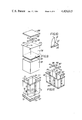
FIG. 9 is an exploded view of a container in accordance with the present invention;
FIG. 10 is an enlarged view of a corner of a portion of the container of FIG. 8 illustrated in the circle; and
FIG. 11 is a perspective view of an alternative form of container construction.
DESCRIPTION OF THE PREFERRED EMBODIMENTS
Referring to FIG. 1 this shows a standard ISO pallet 1 on which is located a container indicated generally by 2. The container has four walls 3, 4, 5 and 6 which are formed from Triwall triple wall thickness corrugated cardboard. The top of each wall is formed into an integral flap such as 7, 8, 9 and 10 which can be folded over to form the top. It will be appreciated that the flaps need not extend completely over the top of the container. Similar flaps or extensions are formed on the bottom of each of the walls to be folded in to form the bottom of the container.
Located within the container are four wooden support struts or posts such as 11, 12, 13, and 14. Each of the posts is formed of wood and has a size approximately 5 cm×8 cm. The wooden posts extend for the entire height of the container and are located in place on the external walls of the container by means of turn buckles such as turn buckle or toggle 15. The toggle or turn buckle 15 is rotatably mounted on the post and can be pushed through an elongate slot 16 in the wall 3 and rotated to locate the toggle firmly in position and hence locate the upright post 11 firmly in position. For standard pallets of 1 m plan area it has been found preferable to use two toggles and further it has been found preferable to use a reinforcing plate 17 to spread the load of the lower toggle 18 over a greater area. The spreader or reinforcing plate 17 may be formed with integral corners such as 19 which dig into the corrugated cardboard to locate it firmly in position. If desired the spreader or reinforcing plate 17 may be provided with corrugations to increase its resistance to bending.
As can be clearly seen, in the upper regions of the container there is provided a pair of tension members 20 and 21. The tension members are in the form of steel straps which are located to interconnect opposing support struts 12 and 14 and 11 and 13 respectively. The tension members have integrally formed tabs such as 22 (FIG. 2) which frequently engage the support struts.
Located within the cardboard container is a fabric reinforced flexible bag illustrated dotted at 23. It has been found that with a standard 1.12 m2 pallet a container having a volume of about 1 m3 can be provided directly on the pallet without the need for any external reinforcing collar to be provided. This means that the full plan area of the pallet can be used and the container can have a maximum internal volume for the transport of fluids.
The pallets may be stacked one on top of the other and the support struts 11, 12, 13 and 14 provide strength to the container such that stacking can comfortably occur.
Referring to FIG. 3 this shows an alternative form of tension means in the form of a pair of metal straps 24, 25 which are formed with an enlarged central region 26. The enlarged central regions are spot welded together as at 27 and are provided with an aperture 28 through which the entry valve for the container 23 can be passed.
Referring to FIG. 4 this shows in more detail the toggle and reinforcing plate. The toggle 29 is inserted through an aperture 30 in the plate and wall and rotated to engage with the reinforcing plate 31 and hold the plate firmly against the wall of the container.
Referring to FIG. 5 this shows an alternative form of tension means in a container generally illustrated as 40. The container is supported on a standard ISO pallet 41 and is formed of a cubic fibreboard body 42 having extension flaps 43, 44, 45 and 46 forming the upper end of the container. The lower end has similar extension flaps not shown. As before there are four support posts 47 to 50 which in this embodiment are bolted to the walls of the container. Bolts such as 51 are used and the load imposed by the bolts is supported by spreader plates 52. As before two bolts and spreader plates per post are used as is clearly illustrated in the drawings. In the embodiment illustrated in FIG. 5 the loads imposed on the posts tending to spread them apart are restrained by a square tension member indicated generally as 53. The tension member is in the form of an open square or window frame having four legs 54, 55, 56 and 57. The member 53 is secured to each of the posts 47 to 50 as is illustrated in more detail in FIG. 7 and as will be explained below.
The loads imposed on the posts such as post 47 are generally in the direction of the arrow 58. The picture frame 53 restrains the outward movement of the posts 47 to 50 by each leg being in tension in a similar manner to the method illustrated in connection with the embodiment shown in FIG. 1. It can be seen by resolving the forces acting in the legs of the picture frame 54 to 57 that the forces 58 can be resolved into pure tensile components in the legs 54 to 57. As before a fluid-tight bag 59 is located inside the container to hold the liquid.
Referring to FIG. 6 there is shown in plan view the picture frame member 53 which is secured to each of the upright posts 47 to 50. The most convenient method of securing the picture frame to the posts is illustrated in FIG. 7. It can be seen that the corners of the picture frame are bent over as at 60 and slip over the back of the post such as post 50. If required the bent-over flaps could be nailed to the post 50.
In an alternative form of tension means illustrated in FIG. 8 the tension means comprises a wire loop 61 formed at each corner with a downwardly directed peg 62. The ends of the loop may be formed to go into a single peg as at 63. The wire loop is held in the posts by driving the pegs 62 into the posts in the manner of nails.
For ease of understanding there is illustrated in FIG. 9 an exploded perspective view of a container in accordance with the present invention. The container is located on a wooden pallet 70 of conventional design. Located immediately on top of the wooden pallet is a fibreboard box 71 which has lower end flaps folded over from each of the sides to form a lower end wall 72. The width of the flaps is a half of the width of the wall so that the end flaps meet to form a double layer base. Located within the container 71 is a lower cruciform 73 which engages the lower ends of four wooden posts 74. The wooden posts are each secured to their respective side faces by means of bolts 75 which are secured to the side walls with load spreading plates 76. The upper ends of each of the walls are provided with flaps 77 which are folded later during the construction and filling of the container.
A loose cardboard sheet liner 78 is then inserted into the container. The height of the sheet 78 is approximately the same as the height of the container 71. This protects the flexible bag from chafing against the post 74.
After the liner 78 has been inserted the flexible bag 79, which has been taped to a cardboard base 80, is located in the container. The cardboard base 80 serves to hold the bottom of the flexible bag 79 accurately in position within the container and eases filling of the container with liquid. When using very thin flexible bags it has been discovered that in the absence of locating the bottom of the bag accurately in the container 71 the bottom can become creased and the creases are held in position by the weight of liquid filling the bag. As is illustrated in detail in FIG. 10 it can be seen that the corners of the base 81 of the bag 80 are taped to the cardboard sheet 81 by means of conventional flexible transparent tape such as 82.
The upper corners of the bag 79 are each provided with extensions 83, 84. These extensions may be in the form of loops or simple strips. The extensions are laid out through the corners of the container in the space between the edges of the flaps 77. Thus the extension 84 would be taken through the gap 85 and held in position on the fibreboard container by means of a suitable adhesive tape.
The upper cruciform 86 would then be located over the flexible container and secured to the upper ends of the wooden posts 74. The filler aperture 87 is then located in the aperture 88 in the cruciform 86. The flaps 77 are then turned over on top of the container and taped in position. The container may then be filled with liquid and after filling the filler aperture 87 can be released from the cruciform 86 to reduce excess tension loads on the material of the bag 79. The cardboard cap 89 is then placed on top of the container and the entire filled container can then be banded to the pallet 70 by use of steel bands in the conventional manner.
It will be appreciated that although there is described above containers utilising only one vertical post per side, if the length of the container became greater than that for which one post was suitable two or more posts per side could be used. Such an arrangement is illustrated in FIG. 11 and it can be seen that the side wall 90 of the container is provided with a pair of posts 91, 92. The upper and lower cruciforms are each provided with a single spine 93 to interconnect end posts 94 and 95 with a pair of cross members 96, 97 to interconnect posts 91 and 98 and 92 and 99 respectively.
Clearly, each of the end walls could be provided with two posts and it may be desired to provide three or more posts on one or more sides.
It will be appreciated that lower tension means are provided at the lower end of each of the posts in the container. Clearly the lower tension means could be of the same type as the upper tension means or alternatively different types could be used at the top and bottom of the container.

Claims (21)

We claim:
1. An intermediate bulk container for liquids comprising a liquid-tight inner bag, an outer skin of polygonal shape and a top and base formed of flap extensions of the walls of the skin, a plurality of support struts, each located in an upright position away from the corner on the inside face of one side wall, each wall being provided with at least one rigid support strut, and the rigid support struts being secured to their respective side walls, in which there is provided upper tension means to interconnect the upper ends of the support struts so as substantially to prevent the upper ends moving apart and lower tension means to interconnect the lower ends of the support struts so as substantially to prevent the lower ends moving apart, the upper and lower tension means being located between the ends of the inner bag and the flap extensions of the walls and including integral tags to engage the support struts between the support struts and the wall of the container, the upper end flaps being of such a length that, when folded over to form a top to the container, they permit access to the liquid-tight inner bag.
2. A container as claimed in claim 1 in which the upper end flaps are folded over to form the upper end and secured in position prior to filling the liquid-tight bag.
3. A container as claimed in claim 2 in which the upper end flaps are secured with self-adhesive tape.
4. A container as claimed in claim 1 in which the base of the liquid-tight bag is secured to a sheet of material prior to insertion into the container.
5. A container as claimed in claim 1 in which the base of the liquid-tight bag is secured to the base of the container prior to filling.
6. A container as claimed in claim 4 in which the upper corners of the liquid-tight bag are secured to the corners of the container after insertion into the container.
7. A container as claimed in claim 6 in which the upper corners of the liquid-tight bag are provided with integral extensions which are secured to the corners of the container.
8. A container as claimed in claim 7 in which the integral extensions are secured to the outside of the corners of the container by self-adhesive tape.
9. A container as claimed in claim 1 in which there are four walls with four support struts, one per wall, each located centrally in a wall, the support struts being connected to the walls of the box by bolts passing through holes in the walls of the box and provided with reinforcing and load spreading plates externally of the walls.
10. A container as claimed in claim 1 in which the outer skin is formed of cardboard or other fibreboard.
11. A container as claimed in claim 10 in which the outer skin is formed of corrugated cardboard.
12. A container as claimed in claim 11 in which the corrugated cardboard skin has at least three corrugated layers superimposed one directly on the other and separated by planar cardboard layers, there being an external planar layer on each face of the assembly.
13. A container as claimed in claim 1 in which one at least of the tension means comprises a rectangle to interconnect adjacent posts.
14. A container as claimed in claim 1 in which an anti-abrasive layer of cardboard or stiff paper is provided between the flexible liquid-tight inner bag and the support struts.
15. A container as claimed in claim 1 in which the lower flaps fold to form a completely covered lower end to the container.
16. A container as claimed in claim 1 in which the liquid-tight bag is formed of flexible plastics material.
17. A container as claimed in claim 1 in which it has a plan area substantially identical to that of a standard pallet.
18. A container as claimed in claim 1 in which there is provided a lid for the filled container.
19. A kit of parts for a container as claimed in claim 1 including, in a disassembled condition, an outer skin, an inner liquid-tight bag, support struts and upper and lower tension means.
20. A kit of parts as claimed in claim 19 also including an abrasion-resistant inner liner and a lid.
21. An intermediate bulk container for liquids comprising a liquid-tight inner bag inserted into an outer skin of polygonal shape, said skin having a top and base formed of flap extensions of the walls of the skin, a plurality of support struts, each located in an upright position away from the corner on the inside face of one side wall, each wall being provided with at least one rigid support strut, and the rigid support struts being secured to their respective side walls, in which there is provided upper tension means to interconnect the upper ends of the support struts so as substantially to prevent the ends moving apart and lower tension means to interconnect the lower ends of the support struts so as substantially to prevent the ends moving apart, the upper end flaps being of such a length that, when folded over to form a top to the container, they permit access to the liquid-tight inner bag, the inner bag having a base secured to a sheet of material prior to insertion into the skin and the upper corners of the inner bag being secured to the corners of the skin after insertion into the skin.
US06/263,735 1980-05-17 1981-05-14 Container Expired - Fee Related US4426015A (en)

Applications Claiming Priority (4)

Application Number Priority Date Filing Date Title
GB8016408 1980-05-17
GB8016408 1980-05-19
GB8103019 1981-01-31

Publications (1)

Publication Number Publication Date
US4426015A true US4426015A (en) 1984-01-17

Family

ID=26275556

Family Applications (1)

Application Number Title Priority Date Filing Date
US06/263,735 Expired - Fee Related US4426015A (en) 1980-05-17 1981-05-14 Container

Country Status (6)

Country Link
US (1) US4426015A (en)
EP (1) EP0040476B1 (en)
AU (1) AU545837B2 (en)
CA (1) CA1171370A (en)
DE (1) DE3161309D1 (en)
IL (1) IL62795A (en)

Cited By (49)

* Cited by examiner, † Cited by third party
Publication number Priority date Publication date Assignee Title
US4614277A (en) * 1984-05-22 1986-09-30 South African Inventions Development Corporation Pallet with tensioned strips and bulk bin
US4676373A (en) * 1984-11-20 1987-06-30 Helmhold Schneider Plastic pallet container
US4771917A (en) * 1986-12-17 1988-09-20 Connelly Containers, Inc. Container for fluent material
US4793519A (en) * 1987-03-23 1988-12-27 Hoover Group, Inc. Composite shipping container
US4821880A (en) * 1987-07-27 1989-04-18 Essex Group, Inc. Palletized structure containing spools
US4830191A (en) * 1981-11-26 1989-05-16 Imperial Chemical Industries Plc Intermediate bulk containers
EP0324889A2 (en) * 1988-01-20 1989-07-26 Productos Coral S.A. A container for product transport and distribution
US4919306A (en) * 1986-12-17 1990-04-24 Connelly Containers, Inc. Container for fluent material including a ring-like holder for a bag
US4927037A (en) * 1987-09-30 1990-05-22 Boots Gerardus A M Container for fluids, solids having flow properties of the like
US4930661A (en) * 1987-03-23 1990-06-05 Hoover Group, Inc. Composite shipping container
US4930632A (en) * 1988-12-05 1990-06-05 Eckert Robert L Hazardous liquid containment tray
US4949872A (en) * 1986-12-17 1990-08-21 Connelly Containers, Inc. Stackable fluent material container
US5036976A (en) * 1988-12-05 1991-08-06 Containment Corporation Hazardous liquid containment tray
US5147039A (en) * 1988-12-05 1992-09-15 Containment Corporation Containment tray
US5163555A (en) * 1990-10-11 1992-11-17 Georgia-Pacific Corporation Hazardous waste disposal container
US5232120A (en) * 1991-06-04 1993-08-03 21St Century Containers, Ltd. Container for bulk liquids and solids
US5323911A (en) * 1992-09-11 1994-06-28 The Morning Star Packing Co. Palletized container having discrete compartments formed by dividers
US5328268A (en) * 1992-10-30 1994-07-12 Custom Packaging Systems, Inc. Bulk bag with restrainer
US5375741A (en) * 1993-05-12 1994-12-27 Encon, Inc. Container for bulk material and its method of manufacture
US5421804A (en) * 1992-10-30 1995-06-06 Custom Packaging Systems, Inc. Bulk bag with restrainer
FR2719823A1 (en) * 1994-05-13 1995-11-17 Lorraine Laminage Transport crate for bulk farm products
US5555980A (en) * 1994-09-23 1996-09-17 Johnson's Trading Post, Inc. Collapsible palletized container
US5749513A (en) * 1996-08-23 1998-05-12 Innovative Enterprises, Inc. Corrugated paperboard box with reinforced side walls
US5794818A (en) * 1995-11-09 1998-08-18 Romeo-Rim, Inc. Container for bulk materials
US5842566A (en) * 1997-07-09 1998-12-01 Rubbermaid Incorporated Merchandizing display carton for handled goods
US5862917A (en) * 1997-09-30 1999-01-26 Trienda Corporation Pallet sleeve clip with visible positive open and closed positions
US5897211A (en) * 1996-02-05 1999-04-27 Hafer; Harold Franklin Flexible bulk container with supporting side beams
US5921427A (en) * 1997-09-08 1999-07-13 Giannone; Benny Trash discriminator device
US6010022A (en) * 1994-05-18 2000-01-04 Buckhorn, Inc. Dispensing box for flowable material
US6113270A (en) * 1998-04-16 2000-09-05 Hafer; Harold Franklin Flexible container with supporting side beams
WO2000073155A2 (en) * 1999-05-27 2000-12-07 Safe-Strap Company, Inc. Adjustable pallet guard
WO2001028880A1 (en) * 1999-10-21 2001-04-26 Hafer Harold F Flexible container with supporting side beams
US6240709B1 (en) 1999-07-20 2001-06-05 Linpac, Inc. Collapsible bag for stacking and method thereof
US20050040063A1 (en) * 2003-08-05 2005-02-24 International Paper Company Rigid corrugated bulk container for liquids and semi-liquid fluids
US20060175328A1 (en) * 2005-02-09 2006-08-10 Lapoint John H Iii Collapsible container
US20070029328A1 (en) * 2005-08-04 2007-02-08 Anthony Polisano Decorative pillar container
US20070164023A1 (en) * 2006-01-18 2007-07-19 Lapoint John Iii Internal truss system for semi-rigid containers
US20070175786A1 (en) * 2006-02-02 2007-08-02 Lincoln Global, Inc. Box for welding wire
US20070277707A1 (en) * 2006-05-31 2007-12-06 Robbins Edward S Double stacked pallet system for rolled sheet goods
US20080073353A1 (en) * 2006-09-27 2008-03-27 Lapoint John H Vertical support and single-wrap collapsible container
US20080110712A1 (en) * 2006-11-13 2008-05-15 Strong Ottina M Interactive gift-giving, packaging, and keepsake storage system
US20090242456A1 (en) * 2008-03-28 2009-10-01 Ricoh Company, Ltd. Packaging container and method
US20090301908A1 (en) * 2008-06-05 2009-12-10 Fujitsu Limited Package and packed electronic device
US20110297702A1 (en) * 2010-06-03 2011-12-08 Stephen Gould Corporation Dispensing container with bottom valve
US20110309072A1 (en) * 2010-06-22 2011-12-22 Rio Gonzalez Juan Jose Self-assemblable container for generic use and manufacturing method thereof
US20120234711A1 (en) * 2011-02-22 2012-09-20 Bart Vermeulen Insert ring for a pallet box and pallet box
US10051946B1 (en) * 2011-01-19 2018-08-21 Hydrapak, Inc. Reservoir system and method of use
US20180282018A1 (en) * 2017-03-30 2018-10-04 Kyocera Document Solutions Inc. Crating arrangement
US20180346179A1 (en) * 2017-05-17 2018-12-06 Jason S. Erdie Containers with integrated support structures and methods for making and using the same

Families Citing this family (4)

* Cited by examiner, † Cited by third party
Publication number Priority date Publication date Assignee Title
EP0228971B1 (en) * 1986-01-02 1991-03-27 SOCIETE CONTINENTALE DU CARTON ONDULE SOCAR Société Anonyme dite: Collapsible palletised container
FR2596360B1 (en) * 1986-04-01 1989-02-17 Sotralentz Sa CONTAINER ON PALLET WITH FOLDED AND REINFORCED MESH PROTECTION DEVICE
NL8700063A (en) * 1987-01-13 1988-08-01 Boots Gerardus A M PACKAGING FOR BULK, FLUIDA AND SIMILAR MATERIALS.
EP0703158A1 (en) * 1994-09-26 1996-03-27 Uri Meir Packing system

Family Cites Families (5)

* Cited by examiner, † Cited by third party
Publication number Priority date Publication date Assignee Title
US3036752A (en) * 1959-04-30 1962-05-29 Tri Wall Containers Inc Counter-stressed corrugated board bulk container
US3073500A (en) * 1960-01-08 1963-01-15 Gen Box Company Container
GB1400414A (en) * 1971-10-29 1975-07-16 Tillotsons Corrugated Cases Container
IL47283A (en) * 1975-08-12 1977-05-31 Tillotsons Corrugated Cases Transport container
FR2406573A1 (en) * 1977-10-20 1979-05-18 Gault Rene PALLET CASE

Cited By (65)

* Cited by examiner, † Cited by third party
Publication number Priority date Publication date Assignee Title
US4830191A (en) * 1981-11-26 1989-05-16 Imperial Chemical Industries Plc Intermediate bulk containers
US4614277A (en) * 1984-05-22 1986-09-30 South African Inventions Development Corporation Pallet with tensioned strips and bulk bin
US4676373A (en) * 1984-11-20 1987-06-30 Helmhold Schneider Plastic pallet container
US4771917A (en) * 1986-12-17 1988-09-20 Connelly Containers, Inc. Container for fluent material
US4919306A (en) * 1986-12-17 1990-04-24 Connelly Containers, Inc. Container for fluent material including a ring-like holder for a bag
US4949872A (en) * 1986-12-17 1990-08-21 Connelly Containers, Inc. Stackable fluent material container
US4930661A (en) * 1987-03-23 1990-06-05 Hoover Group, Inc. Composite shipping container
US4793519A (en) * 1987-03-23 1988-12-27 Hoover Group, Inc. Composite shipping container
US4821880A (en) * 1987-07-27 1989-04-18 Essex Group, Inc. Palletized structure containing spools
AU615942B2 (en) * 1987-09-30 1991-10-17 Gerardus Anthonius Maria Boots A container for fluids, solids having flow properties or the like
US4927037A (en) * 1987-09-30 1990-05-22 Boots Gerardus A M Container for fluids, solids having flow properties of the like
EP0324889A2 (en) * 1988-01-20 1989-07-26 Productos Coral S.A. A container for product transport and distribution
EP0324889A3 (en) * 1988-01-20 1990-05-30 Productos Coral S.A. A container for product transport and distribution
US4930632A (en) * 1988-12-05 1990-06-05 Eckert Robert L Hazardous liquid containment tray
US5036976A (en) * 1988-12-05 1991-08-06 Containment Corporation Hazardous liquid containment tray
US5147039A (en) * 1988-12-05 1992-09-15 Containment Corporation Containment tray
US5163555A (en) * 1990-10-11 1992-11-17 Georgia-Pacific Corporation Hazardous waste disposal container
US5373961A (en) * 1991-06-04 1994-12-20 21St Century Containers, Ltd. Transportable, self-supporting container
US5232120A (en) * 1991-06-04 1993-08-03 21St Century Containers, Ltd. Container for bulk liquids and solids
US5323911A (en) * 1992-09-11 1994-06-28 The Morning Star Packing Co. Palletized container having discrete compartments formed by dividers
US5421804A (en) * 1992-10-30 1995-06-06 Custom Packaging Systems, Inc. Bulk bag with restrainer
US5328268A (en) * 1992-10-30 1994-07-12 Custom Packaging Systems, Inc. Bulk bag with restrainer
US5664887A (en) * 1992-10-30 1997-09-09 Custom Packaging Systems, Inc. Bulk bag with restrainer
US5375741A (en) * 1993-05-12 1994-12-27 Encon, Inc. Container for bulk material and its method of manufacture
FR2719823A1 (en) * 1994-05-13 1995-11-17 Lorraine Laminage Transport crate for bulk farm products
US6010022A (en) * 1994-05-18 2000-01-04 Buckhorn, Inc. Dispensing box for flowable material
US5555980A (en) * 1994-09-23 1996-09-17 Johnson's Trading Post, Inc. Collapsible palletized container
US5794818A (en) * 1995-11-09 1998-08-18 Romeo-Rim, Inc. Container for bulk materials
US6109786A (en) * 1996-02-05 2000-08-29 Hafer; Harold Franklin Flexible bulk container with supporting side beams
US5897211A (en) * 1996-02-05 1999-04-27 Hafer; Harold Franklin Flexible bulk container with supporting side beams
US5749513A (en) * 1996-08-23 1998-05-12 Innovative Enterprises, Inc. Corrugated paperboard box with reinforced side walls
US5842566A (en) * 1997-07-09 1998-12-01 Rubbermaid Incorporated Merchandizing display carton for handled goods
US5921427A (en) * 1997-09-08 1999-07-13 Giannone; Benny Trash discriminator device
US5862917A (en) * 1997-09-30 1999-01-26 Trienda Corporation Pallet sleeve clip with visible positive open and closed positions
US6113270A (en) * 1998-04-16 2000-09-05 Hafer; Harold Franklin Flexible container with supporting side beams
US6408768B1 (en) 1999-05-27 2002-06-25 Safe Strap Company, Inc. Adjustable pallet guard
WO2000073155A2 (en) * 1999-05-27 2000-12-07 Safe-Strap Company, Inc. Adjustable pallet guard
WO2000073155A3 (en) * 1999-05-27 2001-03-01 Safe Strap Co Inc Adjustable pallet guard
US6240709B1 (en) 1999-07-20 2001-06-05 Linpac, Inc. Collapsible bag for stacking and method thereof
WO2001028880A1 (en) * 1999-10-21 2001-04-26 Hafer Harold F Flexible container with supporting side beams
US20050040063A1 (en) * 2003-08-05 2005-02-24 International Paper Company Rigid corrugated bulk container for liquids and semi-liquid fluids
US7607564B2 (en) * 2003-08-05 2009-10-27 International Paper Co. Rigid corrugated bulk container for liquids and semi-liquid fluids
US20060175328A1 (en) * 2005-02-09 2006-08-10 Lapoint John H Iii Collapsible container
US7594581B2 (en) 2005-02-09 2009-09-29 Wrangler Corporation Collapsible container
US20070029328A1 (en) * 2005-08-04 2007-02-08 Anthony Polisano Decorative pillar container
US8006855B2 (en) * 2006-01-18 2011-08-30 Wrangler Corporation Internal truss system for semi-rigid containers
US20070164023A1 (en) * 2006-01-18 2007-07-19 Lapoint John Iii Internal truss system for semi-rigid containers
US20070175786A1 (en) * 2006-02-02 2007-08-02 Lincoln Global, Inc. Box for welding wire
US8245846B2 (en) * 2006-02-02 2012-08-21 Lincoln Global, Inc. Box for welding wire
US20070277707A1 (en) * 2006-05-31 2007-12-06 Robbins Edward S Double stacked pallet system for rolled sheet goods
US20080073353A1 (en) * 2006-09-27 2008-03-27 Lapoint John H Vertical support and single-wrap collapsible container
US20080110712A1 (en) * 2006-11-13 2008-05-15 Strong Ottina M Interactive gift-giving, packaging, and keepsake storage system
US20090242456A1 (en) * 2008-03-28 2009-10-01 Ricoh Company, Ltd. Packaging container and method
US7896159B2 (en) * 2008-03-28 2011-03-01 Ricoh Company, Ltd. Packaging container and method
US20090301908A1 (en) * 2008-06-05 2009-12-10 Fujitsu Limited Package and packed electronic device
US8181774B2 (en) * 2008-06-05 2012-05-22 Fujitsu Limited Package
US20110297702A1 (en) * 2010-06-03 2011-12-08 Stephen Gould Corporation Dispensing container with bottom valve
US8794463B2 (en) * 2010-06-22 2014-08-05 Juan José RIO GONZALEZ Self-assemblable container for generic use and manufacturing method thereof
US20110309072A1 (en) * 2010-06-22 2011-12-22 Rio Gonzalez Juan Jose Self-assemblable container for generic use and manufacturing method thereof
ES2404457R1 (en) * 2010-07-22 2013-06-24 Compania De Patentes Del Pacifico Spa CONTAINER CONTAINER FOR SELF-ASSEMBLY GENERIC USE AND MANUFACTURING METHOD OF THE SAME
US10051946B1 (en) * 2011-01-19 2018-08-21 Hydrapak, Inc. Reservoir system and method of use
US20120234711A1 (en) * 2011-02-22 2012-09-20 Bart Vermeulen Insert ring for a pallet box and pallet box
US20180282018A1 (en) * 2017-03-30 2018-10-04 Kyocera Document Solutions Inc. Crating arrangement
US10538361B2 (en) * 2017-03-30 2020-01-21 Kyocera Document Solutions Inc. Crating arrangement
US20180346179A1 (en) * 2017-05-17 2018-12-06 Jason S. Erdie Containers with integrated support structures and methods for making and using the same

Also Published As

Publication number Publication date
AU7003881A (en) 1981-11-26
IL62795A (en) 1983-07-31
EP0040476A1 (en) 1981-11-25
CA1171370A (en) 1984-07-24
DE3161309D1 (en) 1983-12-08
EP0040476B1 (en) 1983-11-02
AU545837B2 (en) 1985-08-01

Similar Documents

Publication Publication Date Title
US4426015A (en) Container
US6000549A (en) Bulk container
US6109786A (en) Flexible bulk container with supporting side beams
US6220755B1 (en) Stackable flexible intermediate bulk container having corner supports
US6113270A (en) Flexible container with supporting side beams
US6244443B1 (en) Octagon shaped stackable flexible intermediate bulk container and method of manufacture
US6575629B1 (en) Collapsible bag
US6015057A (en) Flexible container for flowable materials
US5765707A (en) Modular shipping container
US6203198B1 (en) Composite container for liquids
US6129267A (en) Bulk box container with supporting side beams
WO1997028049A9 (en) Flexible bulk container with supporting side beams
MXPA97000876A (en) Flexible container of bulk material, with sopo side beams
US6516965B1 (en) Stackable collapsible container
CS231172B2 (en) Box for loose solid material
US6491434B2 (en) Flexible container with supporting side beams
GB2079254A (en) Container
US3385504A (en) Bulk pack for cold flow material
US20080073353A1 (en) Vertical support and single-wrap collapsible container
US3248037A (en) Bulk carrier and connector

Legal Events

Date Code Title Description
AS Assignment

Owner name: IMI MARSTON LIMITED, WOBASTON ROAD, FORDHOUSES, WO

Free format text: ASSIGNMENT OF ASSIGNORS INTEREST.;ASSIGNORS:PRESTON, FREDERICK R.;GROSVENOR, RONALD L.;DERRY, CECIL;REEL/FRAME:003926/0078

Effective date: 19810506

MAFP Maintenance fee payment

Free format text: PAYMENT OF MAINTENANCE FEE, 4TH YEAR, PL 96-517 (ORIGINAL EVENT CODE: M170); ENTITY STATUS OF PATENT OWNER: LARGE ENTITY

Year of fee payment: 4

FEPP Fee payment procedure

Free format text: MAINTENANCE FEE REMINDER MAILED (ORIGINAL EVENT CODE: REM.); ENTITY STATUS OF PATENT OWNER: LARGE ENTITY

LAPS Lapse for failure to pay maintenance fees
FP Lapsed due to failure to pay maintenance fee

Effective date: 19920119

STCH Information on status: patent discontinuation

Free format text: PATENT EXPIRED DUE TO NONPAYMENT OF MAINTENANCE FEES UNDER 37 CFR 1.362