US4430784A - Manufacturing process for orifice nozzle devices for ink jet printing apparati - Google Patents
Manufacturing process for orifice nozzle devices for ink jet printing apparati Download PDFInfo
- Publication number
- US4430784A US4430784A US06/232,457 US23245781A US4430784A US 4430784 A US4430784 A US 4430784A US 23245781 A US23245781 A US 23245781A US 4430784 A US4430784 A US 4430784A
- Authority
- US
- United States
- Prior art keywords
- nozzle
- orifice
- ink jet
- jet printing
- groove
- Prior art date
- Legal status (The legal status is an assumption and is not a legal conclusion. Google has not performed a legal analysis and makes no representation as to the accuracy of the status listed.)
- Expired - Lifetime
Links
- 238000007641 inkjet printing Methods 0.000 title claims abstract description 21
- 238000004519 manufacturing process Methods 0.000 title description 6
- 229910052751 metal Inorganic materials 0.000 claims abstract description 15
- 239000002184 metal Substances 0.000 claims abstract description 15
- 238000004080 punching Methods 0.000 claims abstract description 8
- 238000000034 method Methods 0.000 claims description 37
- 238000002360 preparation method Methods 0.000 claims description 3
- VYZAMTAEIAYCRO-UHFFFAOYSA-N Chromium Chemical compound [Cr] VYZAMTAEIAYCRO-UHFFFAOYSA-N 0.000 claims description 2
- 229910052804 chromium Inorganic materials 0.000 claims description 2
- 239000011651 chromium Substances 0.000 claims description 2
- 239000012530 fluid Substances 0.000 description 10
- 239000012528 membrane Substances 0.000 description 9
- 239000002131 composite material Substances 0.000 description 6
- 238000005553 drilling Methods 0.000 description 5
- PXHVJJICTQNCMI-UHFFFAOYSA-N Nickel Chemical compound [Ni] PXHVJJICTQNCMI-UHFFFAOYSA-N 0.000 description 4
- 238000005498 polishing Methods 0.000 description 4
- 238000007639 printing Methods 0.000 description 4
- 238000004140 cleaning Methods 0.000 description 3
- 239000011521 glass Substances 0.000 description 3
- 239000000758 substrate Substances 0.000 description 3
- 238000013459 approach Methods 0.000 description 2
- 230000015572 biosynthetic process Effects 0.000 description 2
- 230000007547 defect Effects 0.000 description 2
- 230000007812 deficiency Effects 0.000 description 2
- 238000013461 design Methods 0.000 description 2
- 239000010437 gem Substances 0.000 description 2
- 238000007689 inspection Methods 0.000 description 2
- 229910052759 nickel Inorganic materials 0.000 description 2
- 230000003287 optical effect Effects 0.000 description 2
- 229910052715 tantalum Inorganic materials 0.000 description 2
- GUVRBAGPIYLISA-UHFFFAOYSA-N tantalum atom Chemical compound [Ta] GUVRBAGPIYLISA-UHFFFAOYSA-N 0.000 description 2
- XUIMIQQOPSSXEZ-UHFFFAOYSA-N Silicon Chemical compound [Si] XUIMIQQOPSSXEZ-UHFFFAOYSA-N 0.000 description 1
- 229910000831 Steel Inorganic materials 0.000 description 1
- 229910052770 Uranium Inorganic materials 0.000 description 1
- 238000003491 array Methods 0.000 description 1
- 239000013078 crystal Substances 0.000 description 1
- 230000032798 delamination Effects 0.000 description 1
- 230000000694 effects Effects 0.000 description 1
- 230000005686 electrostatic field Effects 0.000 description 1
- 229920006333 epoxy cement Polymers 0.000 description 1
- 230000001747 exhibiting effect Effects 0.000 description 1
- 238000013100 final test Methods 0.000 description 1
- 239000005003 food packaging material Substances 0.000 description 1
- 238000009472 formulation Methods 0.000 description 1
- 229910001751 gemstone Inorganic materials 0.000 description 1
- 239000000463 material Substances 0.000 description 1
- 150000002739 metals Chemical class 0.000 description 1
- 239000000203 mixture Substances 0.000 description 1
- 230000000737 periodic effect Effects 0.000 description 1
- 229920001296 polysiloxane Polymers 0.000 description 1
- 230000000717 retained effect Effects 0.000 description 1
- 230000002441 reversible effect Effects 0.000 description 1
- 230000035945 sensitivity Effects 0.000 description 1
- 229910052710 silicon Inorganic materials 0.000 description 1
- 239000010703 silicon Substances 0.000 description 1
- 239000002002 slurry Substances 0.000 description 1
- 229910001220 stainless steel Inorganic materials 0.000 description 1
- 239000010935 stainless steel Substances 0.000 description 1
- 239000010959 steel Substances 0.000 description 1
- 230000001360 synchronised effect Effects 0.000 description 1
- 230000008685 targeting Effects 0.000 description 1
Images


Classifications
-
- B—PERFORMING OPERATIONS; TRANSPORTING
- B41—PRINTING; LINING MACHINES; TYPEWRITERS; STAMPS
- B41J—TYPEWRITERS; SELECTIVE PRINTING MECHANISMS, i.e. MECHANISMS PRINTING OTHERWISE THAN FROM A FORME; CORRECTION OF TYPOGRAPHICAL ERRORS
- B41J2/00—Typewriters or selective printing mechanisms characterised by the printing or marking process for which they are designed
- B41J2/005—Typewriters or selective printing mechanisms characterised by the printing or marking process for which they are designed characterised by bringing liquid or particles selectively into contact with a printing material
- B41J2/01—Ink jet
- B41J2/135—Nozzles
- B41J2/16—Production of nozzles
- B41J2/1621—Manufacturing processes
- B41J2/1632—Manufacturing processes machining
-
- B—PERFORMING OPERATIONS; TRANSPORTING
- B41—PRINTING; LINING MACHINES; TYPEWRITERS; STAMPS
- B41J—TYPEWRITERS; SELECTIVE PRINTING MECHANISMS, i.e. MECHANISMS PRINTING OTHERWISE THAN FROM A FORME; CORRECTION OF TYPOGRAPHICAL ERRORS
- B41J2/00—Typewriters or selective printing mechanisms characterised by the printing or marking process for which they are designed
- B41J2/005—Typewriters or selective printing mechanisms characterised by the printing or marking process for which they are designed characterised by bringing liquid or particles selectively into contact with a printing material
- B41J2/01—Ink jet
- B41J2/135—Nozzles
- B41J2/16—Production of nozzles
- B41J2/162—Manufacturing of the nozzle plates
-
- G—PHYSICS
- G01—MEASURING; TESTING
- G01D—MEASURING NOT SPECIALLY ADAPTED FOR A SPECIFIC VARIABLE; ARRANGEMENTS FOR MEASURING TWO OR MORE VARIABLES NOT COVERED IN A SINGLE OTHER SUBCLASS; TARIFF METERING APPARATUS; MEASURING OR TESTING NOT OTHERWISE PROVIDED FOR
- G01D15/00—Component parts of recorders for measuring arrangements not specially adapted for a specific variable
- G01D15/16—Recording elements transferring recording material, e.g. ink, to the recording surface
- G01D15/18—Nozzles emitting recording material
-
- Y—GENERAL TAGGING OF NEW TECHNOLOGICAL DEVELOPMENTS; GENERAL TAGGING OF CROSS-SECTIONAL TECHNOLOGIES SPANNING OVER SEVERAL SECTIONS OF THE IPC; TECHNICAL SUBJECTS COVERED BY FORMER USPC CROSS-REFERENCE ART COLLECTIONS [XRACs] AND DIGESTS
- Y10—TECHNICAL SUBJECTS COVERED BY FORMER USPC
- Y10T—TECHNICAL SUBJECTS COVERED BY FORMER US CLASSIFICATION
- Y10T29/00—Metal working
- Y10T29/49—Method of mechanical manufacture
- Y10T29/49401—Fluid pattern dispersing device making, e.g., ink jet
-
- Y—GENERAL TAGGING OF NEW TECHNOLOGICAL DEVELOPMENTS; GENERAL TAGGING OF CROSS-SECTIONAL TECHNOLOGIES SPANNING OVER SEVERAL SECTIONS OF THE IPC; TECHNICAL SUBJECTS COVERED BY FORMER USPC CROSS-REFERENCE ART COLLECTIONS [XRACs] AND DIGESTS
- Y10—TECHNICAL SUBJECTS COVERED BY FORMER USPC
- Y10T—TECHNICAL SUBJECTS COVERED BY FORMER US CLASSIFICATION
- Y10T29/00—Metal working
- Y10T29/49—Method of mechanical manufacture
- Y10T29/496—Multiperforated metal article making
-
- Y—GENERAL TAGGING OF NEW TECHNOLOGICAL DEVELOPMENTS; GENERAL TAGGING OF CROSS-SECTIONAL TECHNOLOGIES SPANNING OVER SEVERAL SECTIONS OF THE IPC; TECHNICAL SUBJECTS COVERED BY FORMER USPC CROSS-REFERENCE ART COLLECTIONS [XRACs] AND DIGESTS
- Y10—TECHNICAL SUBJECTS COVERED BY FORMER USPC
- Y10T—TECHNICAL SUBJECTS COVERED BY FORMER US CLASSIFICATION
- Y10T29/00—Metal working
- Y10T29/49—Method of mechanical manufacture
- Y10T29/4998—Combined manufacture including applying or shaping of fluent material
- Y10T29/49982—Coating
- Y10T29/49986—Subsequent to metal working
-
- Y—GENERAL TAGGING OF NEW TECHNOLOGICAL DEVELOPMENTS; GENERAL TAGGING OF CROSS-SECTIONAL TECHNOLOGIES SPANNING OVER SEVERAL SECTIONS OF THE IPC; TECHNICAL SUBJECTS COVERED BY FORMER USPC CROSS-REFERENCE ART COLLECTIONS [XRACs] AND DIGESTS
- Y10—TECHNICAL SUBJECTS COVERED BY FORMER USPC
- Y10T—TECHNICAL SUBJECTS COVERED BY FORMER US CLASSIFICATION
- Y10T29/00—Metal working
- Y10T29/49—Method of mechanical manufacture
- Y10T29/49995—Shaping one-piece blank by removing material
- Y10T29/49996—Successive distinct removal operations
Definitions
- the present invention relates to nozzle devices having one or more orifices suitable for the discharge of ink droplets in ink jet printing apparati.
- Ink jet printing has gained wide acceptance due to the ability of ink jet printing devices to put nonimpact generated images onto a surface at very high character speeds.
- the recent increase in data communications channels and the capabilities to store and process images electronically necessitates the use of equipment for rapidly making images on a receiving surface.
- the receiving surface may be paper or even food packaging materials such as metal containers, plastic bags and the like.
- a newer method of droplet ejection is the drop-on-demand technique, which converts an electrical signal to a pressure pulse in an ink chamber, causing a single droplet of ink to be ejected in response to each electrical impulse. Since only one droplet is ejected for each pulse and since this method does not employ resonance, this method produces droplets in any sequence.
- a third method of droplet ejection is called "intermittent".
- the process can be turned on and off, but it takes a few droplets to get started and a few droplets to stop the process.
- This method employs a high voltage platen behind the receiving surface, toward which an ink droplet in the nozzle would be attracted. Nearer the nozzle is a valving electrode. When this electrode is given the proper charge, the total attractive forces of the platen and the electrode pull the droplet from the nozzle toward the print receiving surface. When the voltage is set oppositely, the droplet stays in the nozzle.
- a first droplet placement technique is known as electrostatic deflection. Using this droplet placement technique, a droplet is given an electrical charge as it leaves the nozzle. As it flies toward the print receiving surface, it passes between electrically-charged deflection plates. The charge on the droplet causes it to be attracted toward one of the plates and away from the other. These forces "steer" it to the proper position on the print receiving surface.
- a second droplet placement technique is known as nozzle movement.
- the droplets are placed at the proper position by moving the nozzle to the position directly in front of the receiving surface where the droplet is suppose to impinge.
- the nozzle that moves in both the horizontal and vertical directions has the potential of putting marks anywhere on a receiving surface.
- a third droplet placement technique is known as the multinozzle configuration technique.
- droplet placement can be achieved by selecting which nozzles will be used to eject the ink droplet.
- Configurations of nozzle arrays can be designed and manufactured for controlling either horizontal or vertical placement.
- a fourth droplet placement technique is a paper movement technique. Droplet placement can be achieved by moving the paper or print receiving surface to the proper location in relation to the ink jet nozzle.
- the nozzles are equipped with extremely small orifices having diameters of from 7 ⁇ to 60 ⁇ in order to emit the fine jets of ink which break up into small droplets 13 ⁇ to 115 ⁇ in diameter.
- the small size of the nozzles and the nozzle orifices makes them difficult to manufacture reproducibly and also makes the identification of sources of variable performance difficult to diagnose.
- a plurality of nozzle configurations have been employed in ink jet printing, such nozzles being identified as conical nozzles, cylindrical nozzles, square nozzles and composite nozzles.
- the conical nozzle consists of a conical section, normally 50° half angle terminated by a circular cylindrical section.
- Such nozzles are commonly manufactured from watch jewels by a four-step process consisting of (1) cone drilling using conventional high speed drills, (2) orifice drilling using ultrasonic drilling of the cylindrical section, (3) nozzle orifice polishing using thin wires and a polishing slurry, and (4) lapping and polishing of the nozzle face to desired length and finish.
- the finished jewel nozzle must then be mounted in a bushing before it is suitable for use in an ink jet printing device.
- the cylindrical nozzle configuration consists of a circular cylindrical shape with a prescribed degree of entrance surrounding.
- Glass is commonly employed in the fabrication operation which consists of the following steps: (1) glass-tube pulling, using a specially designed furnace; (2) slicing and lapping, using conventional equipment; (3) nozzle polishing, using soft pads for final surface finish and long hair pads for entrance surrounding; and (4) nozzle mounting, using epoxy cement or glassing directly to an adaptor plate.
- Cylindrical nozzles have been found to be sensitive to the degree of entrance rounding of the nozzle; for instance, sharp entranced nozzles are found to display directional instabilities.
- the long capillary lengths which are inherent in glass nozzles cause a high pressure drop across the orifice which necessitates the use of sophisticated and expensive pumps to deliver the ink supply.
- composite nozzles have been devised such as the nozzles set forth in U.S. Pat. No. 3,958,255.
- the composite nozzle employs a substrate having a large diameter entrance opening therein which may be in the shape of a trunicated pyramid.
- a membrane overlays the planar substrate and the membrane is then selectively eroded to form a small orifice therein, the membrane preferably being a silicon membrane.
- the composite structure overcomes certain notable deficiencies such as directional sensitivity, the composite structure has inherent weaknesses due to the high pressure and velocities to which the nozzles are subjected, the pressures and velocities causing delamination of the membrane portion of the laminate structure.
- the shape meeting angle of the membrane and substrate creates high turbulence in the passage of ink through the composite structure.
- 3,958,255 is prepared from a silicone membrane which is secured to a substrated having parametric holes disposed therein by cementing the two structures together.
- the membrane which has appropriately disposed orifices etched therein, is subject to being detached by the high ink pressures employed.
- the patentee states that the laminate may be implaced in the reverse direction.
- a positioning inhibits good fluid flow properties and, moreover, the membrane which has been etched in order to achieve the multiorifice configuration is not a suitable surface for the circuitry which is frequently necessary for drop synchronization.
- nozzles are often subjected to periodic cleaning operations.
- the cleaning operation is an ultrasonic bath cleaning operation which exerts extreme stresses on the jet and hence necessitates a robust mettalic design for jets so cleaned.
- an improved nozzle suitable for ink jet printing may be obtained if the orifice portion of a metallic nozzle is of a critical thickness, e.g. desirably less than 1,500 microns and preferably less than about 1,000 microns, if the portion of the orifice adjacent to the outlet side of the nozzle is cylindrical, i.e., generated by a line parallel to the axis, advantageously for a distance ranging from about 0.25 to 5 and preferably from about 0.5 to 3 times the diameter of the outlet, and if the cylindrical portion merges smoothly with a frustoconical section divergent toward the inlet side and meeting the cylindrical portion at a small angle hereinafter referred to as the meeting angle.
- a critical thickness e.g. desirably less than 1,500 microns and preferably less than about 1,000 microns
- the portion of the orifice adjacent to the outlet side of the nozzle is cylindrical, i.e., generated by a line parallel to the axis, advantageously for a distance
- the meeting angle is twice the angle between the orifice axis and a tangent to the divergent section at a location spaced interiorly of the interior end of the cylindrical portion by a distance equal to 100 percent of the diameter of the cylindrical portion.
- the meeting angle is less than about 60 degrees and preferably less than about 35 degrees. While most commonly the cylindrical portion generated by a line parallel to the axis of the orifice will be circular in cross section, it should be understood that other geometric cross sections are contemplated.
- a plurality of nozzle members suitably aligned for use in ink jet printing may be obtained by grooving a metal plate member with one or more grooves and then disposing from 1 to 1,000 or more orifices longitudinally along the groove or grooves.
- the orifices may be spaced from 500 ⁇ to 2500 ⁇ from each other.
- the grooves may be disposed in parallel alignment or may intersect each other.
- the intersecting grooves will intersect at 90 degree angles.
- the plate member must be of sufficient thickness to prevent warping and therefore thicknesses of from 500 to 5000 microns and preferably from 750 to 5000 microns are employed.
- the thickness of the plate is then reduced to dimensions suitable for nozzle orifices by grooving.
- the grooves are preferably V-shaped although other geometric shapes may be employed.
- the depth of the groove should be such that the deepest part of the groove is within 25 ⁇ to 250 ⁇ of the opposite face of the plate.
- the grooves themselves, when in parallel alignment, may be positioned, measured from groove center to groove center, a distance of up to 200 ⁇ of each other.
- the orifices themselves are constructed according to those configurations previously set forth for the single nozzle members. However, a meeting angle of less than about 60 degrees and preferably less than about 35 degrees must be maintained between the cylindrical section and the adjacent conical section to prevent turbulent flow of ink through the nozzle.
- the sequence in which the sections are formed in the metal is from largest diameter to smallest diameter.
- the most pointed, weakest tools need operate upon a minimum thickness of metal.
- a conical punch of wide angle e.g., about 30° to 100° and preferably about 50° to 60°, is pressed into the metal.
- a narrower angle punch is then pressed into the metal to the requisite distance so that a subsequently produced cylindrical section will be of the desired height.
- each depression serves as a seat to ensure proper positioning of the tool for producing the next depression.
- This technique is applicable even for orifices with relatively wide meeting angles; advantageously the difference between the meeting angles of successive conical sections is at least about 20°, although close spacing of holes may sometimes render it impractial to observe this preference.
- two or more of these steps may be performed simultaneously by employing a suitably profiled tool, e.g., a tool having a frustoconical portion surmounted by a smaller angle conical portion and/or a cylindrical portion.
- a suitably profiled tool e.g., a tool having a frustoconical portion surmounted by a smaller angle conical portion and/or a cylindrical portion.
- a curved portion having, for example, a hyperbolic or parabolic profile.
- the orifice of the apparatus of this invention may be other than circular in cross section.
- Cross sections such as, for instance, triangles and quadralaterals may be employed. Rectangles are preferred among the quadralateral cross sections.
- the total cross sectional area should be in the range of 125 ⁇ 2 to 3000 ⁇ 2 . While these dimensions are normally obtained by drilling and/or punching operations, the cross sectional area of the orifice may also be changed or modified by elecroplating with chromium.
- the process sequence employed is largely determined by the hardness of the metal being processed.
- steel, nickel and tantalum are preferred metals.
- the punching operation be followed by a drilling operation in order to obtain the cylindrical portion.
- the entire operation be a punching operation.
- the cylindrical portion may be either punched or drilled.
- tantalum is being processed, it is preferred that the entire operation be a punching operation.
- the final process step is the removal of the burr at the exit portion.
- the initial process step in the preparation of a multi-orifice nozzle is, of course, the grooving of the plate member.
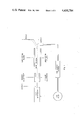
- FIG. 1 is a schematic illustration of one form of ink jet printing apparatus.
- FIG. 2 is a cross-sectional view of a prior art conical nozzle.
- FIG. 3 is a projected view of a prior art cylindrical nozzle.
- FIG. 4 is a projected view of a square nozzle.
- FIG. 5 is a cross-sectional view of a single orifice nozzle of the instant invention.
- FIGS. 6 and 7 are sectional views showing how to determine the meeting angle for countersinks which are not conical.
- FIG. 7 is a partially broken projected view of longitudinally aligned plural orifice nozzle of the instant invention.
- FIG. 9 is a partially broken projected view of a longitudinally and horizontally aligned plural orifice nozzle of the instant invention.
- FIG. 10 is a not-to-scale partially broken cross-sectional view taken along the line X, X of FIG. 8 of the drawings.
- FIG. 11 is a not-to-scale partially broken cross-sectional view taken along the line XI, XI of FIG. 9 of the drawings.
- FIG. 1 of the drawings conductive ink under pressure is forced through a small nozzle to form a flow stream.
- the flow stream would normally break up into drops of quasi-random size and spacing.
- the drop formation can be controlled by vibrating the ink within the nozzle cavity at a fixed ultrasonic frequency.
- the pressure waves cause the flow stream to break up into a stream of drops of uniform size and spacing at a well defined distance from the nozzle.
- a voltage applied at a charge electrode surrounding the breakup point induces an electrical charge of a specific predetermined magnitude on the forming drop. This charge is retained by the drop throughout its flight to the recording surface.
- the stream of drops passes through an electrostatic field formed by a fixed high voltage across a pair of deflection plates.
- a drop can be deflected vertically a desired amount. If, in forming a character, a particular space in a scan is to be left white, it is blanked by leaving the drops uncharged. These undeflected drops are intercepted by a gutter and recycled to the ink reservoir. As drops are deflected vertically, the printhead is driven horizontally at constant speed. Thus, drops are deposited in appropriate positions within a raster area to form the desired character.
- the apparatus as set forth in FIG. 1 is only one form of a plurality of ink jet printing devices
- the ink jet printing apparatus of FIG. 1 employ one or more nozzle members.
- the nozzle members of the prior art may be found in a wide variety of designs, such as for instance the jeweled conical nozzle of FIG. 2, the orifice of which has been lapped to provide a smooth surface free of sharp meeting angles, the glass cylindrical nozzle of FIG. 3 and the trunicated pyramid nozzle of FIG. 4.
- FIG. 5 of the drawings is not only less difficult to fabricate but has a high degree of orifice-to-orifice fidelity.
- the meeting angle between the cylindrical portion of the orifice of the nozzle of the instant invention and the conical section of the orifice of the instant invention be less than about 60 degrees and preferably less than about 35 degrees.
- the angle as previously defined, is easily determined where the walls of the conical section are straight. Where, however, the walls of the conical section are either convex or concave, the meeting angle may be measured as illustrated in FIGS. 6 and 7 of the drawing.
- the elevation A at which the orifices cease to be cylindrical, is marked.
- the width of the orifice at elevation A is determined and 100 percent of this width is marked above A as plane B, perpendicular to the axes of the orifice. Tangents are drawn to the two points where B intersects the outline of the orifice and the meeting angle alpha is the angle between these tangents.
- FIG. 8 there is shown as a projected view, a longitudinally aligned plural orifice nozzle of the instant invention wherein a plate member 20 having a thickness great enough so as to retain its dimensional rigidity but too thick to be appropriate for an ink jet nozzle has a V-shaped groove member 21 disposed therein.
- Conical apertures 22 are formed by punching a conical countersink to the desired depth in groove member 21.
- the apex of groove member 21 serves as a guide for the more pointed countersink employed in punching conical members 22.
- a cross section of FIG. 8 taken along the line X, X illustrates, in FIG. 10, a cross section of one form of the multiorifice nozzle of the instant invention.
- groove member 21 has a conical portion 22 punched therein.
- Conical portion 22 then has cylindrical portion 23 drilled or punched, depending upon the metallic nature of plate member 20.
- the groove or grooves 31 may have curved walls rather than the V-shaped configuration as set forth in FIG. 8 of the drawings. Moreover, the groove members 31 may intersect each other at right angles whereby the conical members 32 disposed therein are horizontally and vertically aligned. In any event, however, plate member 30 is of sufficient depth to have structural rigidty, that depth being greater than the desirable depth for the formulation of a nozzle suitable for ink jet printing, the desired depth being obtained by grooving plate member 30 with trough members 31.
- the groove members 31 intersect at right angles, the groove members 31 having disposed therein a plurality of spaced orifices comprising conical portions and cylindrical portions.
- the orifices employed in the nozzles of the instant invention be devoid of sharp meeting angles, particularly in the areas where the conical portion joints the cylindrical portion. Where sharp meeting angles are present, that is to say, angles in excess of 75 degrees, turbulence is produced in the fluid flow of the ink. The turbulence results in nonuniform ink drop size and, in extreme cases, the generation of large drops accompanied by smaller satellite drops, all of which are generated at random spacing intervals. It is also essential that the cylindrical portion of the orifice have a height of no more than 5 times the diameter of the orifice outlet. If this maximum height limitation is exceeded, high fluid pressure drops will result and special fluid pumps may be employed. When, however, all of the critical parameters of the nozzles of the instant invention are met, turbulence free fluid flow is obtained and ink drops of uniform size and spacing are obtained.
Abstract
Description
Claims (2)
Priority Applications (1)
| Application Number | Priority Date | Filing Date | Title |
|---|---|---|---|
| US06/232,457 US4430784A (en) | 1980-02-22 | 1981-02-09 | Manufacturing process for orifice nozzle devices for ink jet printing apparati |
Applications Claiming Priority (2)
| Application Number | Priority Date | Filing Date | Title |
|---|---|---|---|
| US06/123,629 US4282533A (en) | 1980-02-22 | 1980-02-22 | Precision orifice nozzle devices for ink jet printing apparati and the process for their manufacture |
| US06/232,457 US4430784A (en) | 1980-02-22 | 1981-02-09 | Manufacturing process for orifice nozzle devices for ink jet printing apparati |
Related Parent Applications (1)
| Application Number | Title | Priority Date | Filing Date |
|---|---|---|---|
| US06/123,629 Division US4282533A (en) | 1980-02-22 | 1980-02-22 | Precision orifice nozzle devices for ink jet printing apparati and the process for their manufacture |
Publications (1)
| Publication Number | Publication Date |
|---|---|
| US4430784A true US4430784A (en) | 1984-02-14 |
Family
ID=26821738
Family Applications (1)
| Application Number | Title | Priority Date | Filing Date |
|---|---|---|---|
| US06/232,457 Expired - Lifetime US4430784A (en) | 1980-02-22 | 1981-02-09 | Manufacturing process for orifice nozzle devices for ink jet printing apparati |
Country Status (1)
| Country | Link |
|---|---|
| US (1) | US4430784A (en) |
Cited By (22)
| Publication number | Priority date | Publication date | Assignee | Title |
|---|---|---|---|---|
| US4574445A (en) * | 1983-07-23 | 1986-03-11 | U.S. Philips Corporation | Method and apparatus for manufacturing a nozzle plate for ink-jet printers |
| US4639568A (en) * | 1984-07-13 | 1987-01-27 | Ex-Cell-O Corporation | Apparatus and method for finishing fuel injector spray tips using EDM |
| US4685185A (en) * | 1986-08-29 | 1987-08-11 | Tektronix, Inc. | Method of manufacturing an ink jet head |
| US4694548A (en) * | 1985-07-09 | 1987-09-22 | Kernforschungszentrum Karlsruhe Gmbh | Method for producing a spinning nozzle plate |
| US5208980A (en) * | 1991-12-31 | 1993-05-11 | Compag Computer Corporation | Method of forming tapered orifice arrays in fully assembled ink jet printheads |
| US5350616A (en) * | 1993-06-16 | 1994-09-27 | Hewlett-Packard Company | Composite orifice plate for ink jet printer and method for the manufacture thereof |
| US5703631A (en) * | 1992-05-05 | 1997-12-30 | Compaq Computer Corporation | Method of forming an orifice array for a high density ink jet printhead |
| US5901425A (en) * | 1996-08-27 | 1999-05-11 | Topaz Technologies Inc. | Inkjet print head apparatus |
| US6214192B1 (en) * | 1998-12-10 | 2001-04-10 | Eastman Kodak Company | Fabricating ink jet nozzle plate |
| EP1179614A3 (en) * | 2000-08-01 | 2003-01-02 | Hewlett-Packard Company | Mandrel for electroforming orifice plates |
| US20040125178A1 (en) * | 2002-08-23 | 2004-07-01 | Seiko Epson Corporation | Liquid ejection head, and method of manufacturing the same |
| US20050086805A1 (en) * | 2003-10-22 | 2005-04-28 | Bergstrom Deanna J. | Mandrel for electroformation of an orifice plate |
| US20050242057A1 (en) * | 2004-04-29 | 2005-11-03 | Hewlett-Packard Developmentcompany, L.P. | Substrate passage formation |
| WO2006069943A2 (en) * | 2004-12-30 | 2006-07-06 | Domino Printing Sciences Plc | Fluid ejection nozzle |
| US20060186231A1 (en) * | 2003-04-11 | 2006-08-24 | Deborah Kosovich | Airless spray nozzle |
| US20080136869A1 (en) * | 2005-12-21 | 2008-06-12 | Jonathan Morgan | Fluid Ejection Nozzle |
| US20110265539A1 (en) * | 2009-07-24 | 2011-11-03 | Ckm Building Material Corp. | Method of making micro-holes on metal plate |
| US9981090B2 (en) * | 2012-06-11 | 2018-05-29 | Stamford Devices Limited | Method for producing an aperture plate |
| US10279357B2 (en) | 2014-05-23 | 2019-05-07 | Stamford Devices Limited | Method for producing an aperture plate |
| US10508353B2 (en) | 2010-12-28 | 2019-12-17 | Stamford Devices Limited | Photodefined aperture plate and method for producing the same |
| US10870175B2 (en) | 2013-09-18 | 2020-12-22 | Cytonome/St, Llc | Microfluidic flow-through elements and methods of manufacture of same |
| EP4088822A1 (en) * | 2021-05-12 | 2022-11-16 | PARI Pharma GmbH | Nebulizing device for an inhalator |
Citations (15)
| Publication number | Priority date | Publication date | Assignee | Title |
|---|---|---|---|---|
| US87385A (en) * | 1869-03-02 | Improved metallic screen for paper-pulp | ||
| US1497530A (en) * | 1924-06-10 | Frantz mobtkusbn | ||
| US2618989A (en) * | 1948-06-01 | 1952-11-25 | John A Cupler | Method of manufacturing orificed members |
| US2649670A (en) * | 1950-07-28 | 1953-08-25 | Ver Glanzstoff Fabriken A G Fa | Method for reconditioning the extruding face of spinnerettes |
| US2714244A (en) * | 1951-10-11 | 1955-08-02 | Metallizing Engineering Co Inc | Method for the production of spray tube orifices for irrigating devices |
| US3044167A (en) * | 1959-02-13 | 1962-07-17 | Const Guinard Soc | Gang cutting and forming punch for the manufacture of filtering elements |
| US3210451A (en) * | 1960-12-01 | 1965-10-05 | Celanese Corp | Spinnerettes |
| US3921916A (en) * | 1974-12-31 | 1975-11-25 | Ibm | Nozzles formed in monocrystalline silicon |
| GB1422388A (en) * | 1972-11-29 | 1976-01-28 | Ibm | Liquid droplet recording apparatus |
| US3958255A (en) * | 1974-12-31 | 1976-05-18 | International Business Machines Corporation | Ink jet nozzle structure |
| US3973717A (en) * | 1975-04-21 | 1976-08-10 | Ppg Industries, Inc. | Bushing fabrication |
| US4014029A (en) * | 1975-12-31 | 1977-03-22 | International Business Machines Corporation | Staggered nozzle array |
| US4106976A (en) * | 1976-03-08 | 1978-08-15 | International Business Machines Corporation | Ink jet nozzle method of manufacture |
| DE2728657A1 (en) * | 1977-06-24 | 1979-01-04 | Siemens Ag | NOZZLE PLATE FOR INK WRITING DEVICES |
| US4169008A (en) * | 1977-06-13 | 1979-09-25 | International Business Machines Corporation | Process for producing uniform nozzle orifices in silicon wafers |
-
1981
- 1981-02-09 US US06/232,457 patent/US4430784A/en not_active Expired - Lifetime
Patent Citations (16)
| Publication number | Priority date | Publication date | Assignee | Title |
|---|---|---|---|---|
| US87385A (en) * | 1869-03-02 | Improved metallic screen for paper-pulp | ||
| US1497530A (en) * | 1924-06-10 | Frantz mobtkusbn | ||
| US2618989A (en) * | 1948-06-01 | 1952-11-25 | John A Cupler | Method of manufacturing orificed members |
| US2649670A (en) * | 1950-07-28 | 1953-08-25 | Ver Glanzstoff Fabriken A G Fa | Method for reconditioning the extruding face of spinnerettes |
| US2714244A (en) * | 1951-10-11 | 1955-08-02 | Metallizing Engineering Co Inc | Method for the production of spray tube orifices for irrigating devices |
| US3044167A (en) * | 1959-02-13 | 1962-07-17 | Const Guinard Soc | Gang cutting and forming punch for the manufacture of filtering elements |
| US3210451A (en) * | 1960-12-01 | 1965-10-05 | Celanese Corp | Spinnerettes |
| GB1422388A (en) * | 1972-11-29 | 1976-01-28 | Ibm | Liquid droplet recording apparatus |
| US3921916A (en) * | 1974-12-31 | 1975-11-25 | Ibm | Nozzles formed in monocrystalline silicon |
| US3958255A (en) * | 1974-12-31 | 1976-05-18 | International Business Machines Corporation | Ink jet nozzle structure |
| US3973717A (en) * | 1975-04-21 | 1976-08-10 | Ppg Industries, Inc. | Bushing fabrication |
| US4014029A (en) * | 1975-12-31 | 1977-03-22 | International Business Machines Corporation | Staggered nozzle array |
| US4106976A (en) * | 1976-03-08 | 1978-08-15 | International Business Machines Corporation | Ink jet nozzle method of manufacture |
| US4169008A (en) * | 1977-06-13 | 1979-09-25 | International Business Machines Corporation | Process for producing uniform nozzle orifices in silicon wafers |
| DE2728657A1 (en) * | 1977-06-24 | 1979-01-04 | Siemens Ag | NOZZLE PLATE FOR INK WRITING DEVICES |
| GB1581204A (en) * | 1977-06-24 | 1980-12-10 | Siemens Ag | Mosaic printer heads |
Non-Patent Citations (6)
| Title |
|---|
| Henderson, C. S., et al., "Nozzle for Ink Jet Printer" from IBM Technical Disclosure Bulletin, vol. 17, No. 11, Apr. 1975, p. 3249. |
| Henderson, C. S., et al., Nozzle for Ink Jet Printer from IBM Technical Disclosure Bulletin, vol. 17, No. 11, Apr. 1975, p. 3249. * |
| Levanoni, M., "Study of Fluid Flow Through Scaled-Up Ink Jet Nozzles," from IBM Journal of Research and Development, vol. 21, No. 1, Jan. 1977, pp. 56-68. |
| Levanoni, M., Study of Fluid Flow Through Scaled Up Ink Jet Nozzles, from IBM Journal of Research and Development, vol. 21, No. 1, Jan. 1977, pp. 56 68. * |
| Talke, F. E., "Voltage-Modulated Binary Ink Jet" from IBM Technical Disclosure Bulletin, vol. 21, No. 5, Oct. 1978, pp. 2001-2002. |
| Talke, F. E., Voltage Modulated Binary Ink Jet from IBM Technical Disclosure Bulletin, vol. 21, No. 5, Oct. 1978, pp. 2001 2002. * |
Cited By (39)
| Publication number | Priority date | Publication date | Assignee | Title |
|---|---|---|---|---|
| US4574445A (en) * | 1983-07-23 | 1986-03-11 | U.S. Philips Corporation | Method and apparatus for manufacturing a nozzle plate for ink-jet printers |
| US4639568A (en) * | 1984-07-13 | 1987-01-27 | Ex-Cell-O Corporation | Apparatus and method for finishing fuel injector spray tips using EDM |
| US4694548A (en) * | 1985-07-09 | 1987-09-22 | Kernforschungszentrum Karlsruhe Gmbh | Method for producing a spinning nozzle plate |
| US4685185A (en) * | 1986-08-29 | 1987-08-11 | Tektronix, Inc. | Method of manufacturing an ink jet head |
| US5208980A (en) * | 1991-12-31 | 1993-05-11 | Compag Computer Corporation | Method of forming tapered orifice arrays in fully assembled ink jet printheads |
| US5703631A (en) * | 1992-05-05 | 1997-12-30 | Compaq Computer Corporation | Method of forming an orifice array for a high density ink jet printhead |
| US5350616A (en) * | 1993-06-16 | 1994-09-27 | Hewlett-Packard Company | Composite orifice plate for ink jet printer and method for the manufacture thereof |
| US5901425A (en) * | 1996-08-27 | 1999-05-11 | Topaz Technologies Inc. | Inkjet print head apparatus |
| US6214192B1 (en) * | 1998-12-10 | 2001-04-10 | Eastman Kodak Company | Fabricating ink jet nozzle plate |
| US6586112B1 (en) | 2000-08-01 | 2003-07-01 | Hewlett-Packard Company | Mandrel and orifice plates electroformed using the same |
| EP1179614A3 (en) * | 2000-08-01 | 2003-01-02 | Hewlett-Packard Company | Mandrel for electroforming orifice plates |
| US20040125178A1 (en) * | 2002-08-23 | 2004-07-01 | Seiko Epson Corporation | Liquid ejection head, and method of manufacturing the same |
| US7052119B2 (en) * | 2002-08-23 | 2006-05-30 | Seiko Epson Corporation | Liquid ejection head, and method of manufacturing the same |
| US20060186231A1 (en) * | 2003-04-11 | 2006-08-24 | Deborah Kosovich | Airless spray nozzle |
| US20070286960A1 (en) * | 2003-04-11 | 2007-12-13 | Nordson Corporation | Airless spray nozzle |
| US20050086805A1 (en) * | 2003-10-22 | 2005-04-28 | Bergstrom Deanna J. | Mandrel for electroformation of an orifice plate |
| US7040016B2 (en) | 2003-10-22 | 2006-05-09 | Hewlett-Packard Development Company, L.P. | Method of fabricating a mandrel for electroformation of an orifice plate |
| US7530169B2 (en) | 2003-10-22 | 2009-05-12 | Hewlett-Packard Development Company, L.P. | Mandrel for electroformation of an orifice plate |
| US20060143914A1 (en) * | 2003-10-22 | 2006-07-06 | Bergstrom Deanna J | Mandrel for electroformation of an orifice plate |
| US7429335B2 (en) * | 2004-04-29 | 2008-09-30 | Shen Buswell | Substrate passage formation |
| US20050242057A1 (en) * | 2004-04-29 | 2005-11-03 | Hewlett-Packard Developmentcompany, L.P. | Substrate passage formation |
| WO2006069943A3 (en) * | 2004-12-30 | 2006-08-24 | Domino Printing Sciences Plc | Fluid ejection nozzle |
| WO2006069943A2 (en) * | 2004-12-30 | 2006-07-06 | Domino Printing Sciences Plc | Fluid ejection nozzle |
| US20080136869A1 (en) * | 2005-12-21 | 2008-06-12 | Jonathan Morgan | Fluid Ejection Nozzle |
| US20110265539A1 (en) * | 2009-07-24 | 2011-11-03 | Ckm Building Material Corp. | Method of making micro-holes on metal plate |
| US8800340B2 (en) * | 2009-07-24 | 2014-08-12 | Ckm Building Material Corp. | Method of making micro-holes on metal plate |
| US10662543B2 (en) | 2010-12-28 | 2020-05-26 | Stamford Devices Limited | Photodefined aperture plate and method for producing the same |
| US11905615B2 (en) | 2010-12-28 | 2024-02-20 | Stamford Devices Limited | Photodefined aperture plate and method for producing the same |
| US10508353B2 (en) | 2010-12-28 | 2019-12-17 | Stamford Devices Limited | Photodefined aperture plate and method for producing the same |
| US11389601B2 (en) * | 2010-12-28 | 2022-07-19 | Stamford Devices Limited | Photodefined aperture plate and method for producing the same |
| US9981090B2 (en) * | 2012-06-11 | 2018-05-29 | Stamford Devices Limited | Method for producing an aperture plate |
| US10512736B2 (en) | 2012-06-11 | 2019-12-24 | Stamford Devices Limited | Aperture plate for a nebulizer |
| US11679209B2 (en) | 2012-06-11 | 2023-06-20 | Stamford Devices Limited | Aperture plate for a nebulizer |
| US10870175B2 (en) | 2013-09-18 | 2020-12-22 | Cytonome/St, Llc | Microfluidic flow-through elements and methods of manufacture of same |
| US11440030B2 (en) | 2014-05-23 | 2022-09-13 | Stamford Devices Limited | Method for producing an aperture plate |
| US11872573B2 (en) | 2014-05-23 | 2024-01-16 | Stamford Devices Limited | Method for producing an aperture plate |
| US10279357B2 (en) | 2014-05-23 | 2019-05-07 | Stamford Devices Limited | Method for producing an aperture plate |
| EP4088822A1 (en) * | 2021-05-12 | 2022-11-16 | PARI Pharma GmbH | Nebulizing device for an inhalator |
| WO2022238464A1 (en) * | 2021-05-12 | 2022-11-17 | Pari Pharma Gmbh | Nebulizing device for an inhalator |
Similar Documents
| Publication | Publication Date | Title |
|---|---|---|
| US4282533A (en) | Precision orifice nozzle devices for ink jet printing apparati and the process for their manufacture | |
| US4430784A (en) | Manufacturing process for orifice nozzle devices for ink jet printing apparati | |
| CA1059197A (en) | Ink jet nozzle structure and method of making | |
| US4613875A (en) | Air assisted ink jet head with projecting internal ink drop-forming orifice outlet | |
| US4106976A (en) | Ink jet nozzle method of manufacture | |
| US5164740A (en) | High frequency printing mechanism | |
| US4014029A (en) | Staggered nozzle array | |
| US5160577A (en) | Method of fabricating an aperture plate for a roof-shooter type printhead | |
| US4343013A (en) | Nozzle plate for ink jet print head | |
| US4364067A (en) | Highly integrated ink jet head | |
| US4209794A (en) | Nozzle plate for an ink recording device | |
| US4420764A (en) | Ink jet printer head | |
| US6378972B1 (en) | Drive method for an on-demand multi-nozzle ink jet head | |
| US5451993A (en) | Ink jet head | |
| US9895887B2 (en) | Liquid ejection head and process for producing the same | |
| US7480993B2 (en) | Method of manufacturing a nozzle plate | |
| US4368477A (en) | Arrangement for a printing head in ink mosaic printing devices | |
| JP3755332B2 (en) | Method for forming nozzle for inkjet head | |
| JP2001010067A (en) | Method for working ejection nozzle of liquid jet recording head, and production of liquid jet recording head | |
| US6390607B2 (en) | Ink jet print head | |
| EP0067948A1 (en) | Method and apparatus for producing liquid drops on demand | |
| US6692103B2 (en) | Ink jet recording head | |
| JP2000218827A (en) | Method for removing fluid from printing head | |
| JPH02194961A (en) | Ink jet recording head | |
| JPH09169116A (en) | Method for forming fluid cavity in component of jet print system |
Legal Events
| Date | Code | Title | Description |
|---|---|---|---|
| STCF | Information on status: patent grant |
Free format text: PATENTED CASE |
|
| MAFP | Maintenance fee payment |
Free format text: PAYMENT OF MAINTENANCE FEE, 4TH YEAR, PL 96-517 (ORIGINAL EVENT CODE: M170); ENTITY STATUS OF PATENT OWNER: LARGE ENTITY Year of fee payment: 4 |
|
| MAFP | Maintenance fee payment |
Free format text: PAYMENT OF MAINTENANCE FEE, 8TH YEAR, PL 96-517 (ORIGINAL EVENT CODE: M171); ENTITY STATUS OF PATENT OWNER: LARGE ENTITY Year of fee payment: 8 |
|
| FEPP | Fee payment procedure |
Free format text: PAYOR NUMBER ASSIGNED (ORIGINAL EVENT CODE: ASPN); ENTITY STATUS OF PATENT OWNER: LARGE ENTITY |
|
| MAFP | Maintenance fee payment |
Free format text: PAYMENT OF MAINTENANCE FEE, 12TH YEAR, LARGE ENTITY (ORIGINAL EVENT CODE: M185); ENTITY STATUS OF PATENT OWNER: LARGE ENTITY Year of fee payment: 12 |
|
| AS | Assignment |
Owner name: HOECHST CELANESE CORPORATION, NEW JERSEY Free format text: MERGER AND NAME CHANGE;ASSIGNORS:AMERICAN HOECHST CORPORATION (DE CORPORATION);CELANESE CORPORATION (DE CORPORATION);REEL/FRAME:014475/0185 Effective date: 19870227 Owner name: CNA HOLDINGS, INC., NEW JERSEY Free format text: CHANGE OF NAME;ASSIGNOR:HNA HOLDINGS, INC. (DE CORPORATION);REEL/FRAME:014515/0141 Effective date: 19990816 Owner name: HNA HOLDINGS, INC., DELAWARE Free format text: CHANGE OF NAME;ASSIGNOR:HOECHST CELANESE CORPORATION;REEL/FRAME:014506/0001 Effective date: 19980102 |
|
| AS | Assignment |
Owner name: DEUTSCHE BANK AG, NEW YORK BRANCH, NEW YORK Free format text: SECURITY INTEREST;ASSIGNOR:CNA HOLDINGS, INC.;REEL/FRAME:014601/0698 Effective date: 20040405 |
|
| AS | Assignment |
Owner name: DEUTSCHE BANK AG, NEW YORK BRANDH, NEW YORK Free format text: SECURITY AGREEMENT;ASSIGNOR:CNA HOLDINGS, INC. (F/K/A CELANESE CORPORATION);REEL/FRAME:015394/0104 Effective date: 20041018 |