US4449024A - Backlighted illuminated keyboard - Google Patents
Backlighted illuminated keyboard Download PDFInfo
- Publication number
- US4449024A US4449024A US06/491,246 US49124683A US4449024A US 4449024 A US4449024 A US 4449024A US 49124683 A US49124683 A US 49124683A US 4449024 A US4449024 A US 4449024A
- Authority
- US
- United States
- Prior art keywords
- overlay
- lamp
- illuminated keyboard
- dome
- diffuser
- Prior art date
- Legal status (The legal status is an assumption and is not a legal conclusion. Google has not performed a legal analysis and makes no representation as to the accuracy of the status listed.)
- Expired - Fee Related
Links
Images
Classifications
-
- H—ELECTRICITY
- H01—ELECTRIC ELEMENTS
- H01H—ELECTRIC SWITCHES; RELAYS; SELECTORS; EMERGENCY PROTECTIVE DEVICES
- H01H13/00—Switches having rectilinearly-movable operating part or parts adapted for pushing or pulling in one direction only, e.g. push-button switch
- H01H13/70—Switches having rectilinearly-movable operating part or parts adapted for pushing or pulling in one direction only, e.g. push-button switch having a plurality of operating members associated with different sets of contacts, e.g. keyboard
- H01H13/702—Switches having rectilinearly-movable operating part or parts adapted for pushing or pulling in one direction only, e.g. push-button switch having a plurality of operating members associated with different sets of contacts, e.g. keyboard with contacts carried by or formed from layers in a multilayer structure, e.g. membrane switches
-
- H—ELECTRICITY
- H01—ELECTRIC ELEMENTS
- H01H—ELECTRIC SWITCHES; RELAYS; SELECTORS; EMERGENCY PROTECTIVE DEVICES
- H01H2215/00—Tactile feedback
- H01H2215/004—Collapsible dome or bubble
- H01H2215/008—Part of substrate or membrane
-
- H—ELECTRICITY
- H01—ELECTRIC ELEMENTS
- H01H—ELECTRIC SWITCHES; RELAYS; SELECTORS; EMERGENCY PROTECTIVE DEVICES
- H01H2219/00—Legends
- H01H2219/028—Printed information
-
- H—ELECTRICITY
- H01—ELECTRIC ELEMENTS
- H01H—ELECTRIC SWITCHES; RELAYS; SELECTORS; EMERGENCY PROTECTIVE DEVICES
- H01H2219/00—Legends
- H01H2219/036—Light emitting elements
- H01H2219/04—Attachments; Connections
-
- H—ELECTRICITY
- H01—ELECTRIC ELEMENTS
- H01H—ELECTRIC SWITCHES; RELAYS; SELECTORS; EMERGENCY PROTECTIVE DEVICES
- H01H2219/00—Legends
- H01H2219/036—Light emitting elements
- H01H2219/042—Light emitting elements replaceable
-
- H—ELECTRICITY
- H01—ELECTRIC ELEMENTS
- H01H—ELECTRIC SWITCHES; RELAYS; SELECTORS; EMERGENCY PROTECTIVE DEVICES
- H01H2219/00—Legends
- H01H2219/054—Optical elements
- H01H2219/056—Diffuser; Uneven surface
-
- H—ELECTRICITY
- H01—ELECTRIC ELEMENTS
- H01H—ELECTRIC SWITCHES; RELAYS; SELECTORS; EMERGENCY PROTECTIVE DEVICES
- H01H2223/00—Casings
- H01H2223/034—Bezel
- H01H2223/036—Bezel forming chamfered apertures for keys
-
- H—ELECTRICITY
- H01—ELECTRIC ELEMENTS
- H01H—ELECTRIC SWITCHES; RELAYS; SELECTORS; EMERGENCY PROTECTIVE DEVICES
- H01H2229/00—Manufacturing
- H01H2229/034—Positioning of layers
-
- H—ELECTRICITY
- H01—ELECTRIC ELEMENTS
- H01H—ELECTRIC SWITCHES; RELAYS; SELECTORS; EMERGENCY PROTECTIVE DEVICES
- H01H2237/00—Mechanism between key and laykey
- H01H2237/006—Guided plunger or ball
-
- H—ELECTRICITY
- H01—ELECTRIC ELEMENTS
- H01H—ELECTRIC SWITCHES; RELAYS; SELECTORS; EMERGENCY PROTECTIVE DEVICES
- H01H2239/00—Miscellaneous
- H01H2239/004—High frequency adaptation or shielding
Definitions
- This invention relates in general to a keyboard assembly, and more particularly to a backlighted illuminated keyboard useful where poor light situations exist, and still more particularly to a backlighted illuminated keyboard that is illuminated by a single lamp which may be easily replaced from the back of the keyboard.
- the present invention overcomes the problems heretofore encountered in illuminated keyboards in providing a keyboard assembly that is illuminated with a single miniature lamp that may be easily replaced when it fails. Moreover, such a single lamp is more economical to operate, dissipates low heat to the keyboard, and requires less current to operate where batteries are the source of power.
- the illuminated keyboard of the present invention also includes tactile feedback in the key areas. More particularly, the keyboard includes a printed circuit board having a plurality of switch sites, a dome at each of the sites coacting therewith to define a switch having tactile feedback, a light diffuser of substantially the same size as the printed circuit board and resting on the printed circuit board.
- Actuating plungers or pins are guidably received by the diffuser such that the lower end of an actuating pin is in alignment with the center of and in engagement with a dome.
- the upper ends of the actuating pins protrude above the diffuser and engage the underside of a graphic overlay made of translucent material and having suitable legends or indicia in alignment with each of the actuating pins.
- the diffuser is of clear plastic and includes a centrally disposed blind hole into which the single illuminating lamp is received for dispersing light through the diffuser.
- the lamp is mounted in a socket formed in the printed circuit board and held in place by a swivel arm at the backside of the board. Swinging the swivel arm to one side allows removal and replacement of the lamp.
- the translucent graphic overlay is of substantially the same dimension as the diffuser and the printed circuit board and rests on top of the diffuser such that it engages the upper ends of the actuating pins.
- a bezel made of light opaque material is disposed over the overlay and defines key depressing areas for the overlay associated with a given switch and its elements. Energization of the lamp thereby disperses light energy through the light diffuser and uniformly over the translucent overlay from the back of the overlay such that the graphics on the overlay can be easily read in poor light conditions.
- a further object of the present invention is to provide a new and improved illuminated keyboard which is illuminated by a single lamp that may be easily removed and replaced from the backside of the printed circuit board.
- a still further object of the present invention is in the provision of an illuminated keyboard that is useful for poor light situations and which is illuminated by a single lamp having a low current requirement and low heat dissipation and which contributes to the overall inexpensive construction of the keyboard.
- FIG. 1 is a perspective view of the illuminated keyboard of the present invention mounted on a panel;
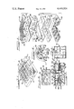
- FIG. 2 is an exploded perspective view of the illuminated keyboard of the invention wherein some of the parts have portions cut away to show underlying parts and for purposes of clarity;
- FIG. 3 is a greatly enlarged detailed vertical sectional view taken substantially along line 3--3 of FIG. 1;
- FIG. 4 is a greatly enlarged perspective cutaway view of the central portion of the printed circuit board and illustrating the manner in which the single lamp may be easily removed and replaced;
- FIG. 5 is a fragmentary bottom plan view of the light diffuser used in the keyboard of the invention.
- FIG. 6 is a bottom plan view of the bezel.
- the illuminated keyboard of the present invention is generally designated by the numeral 10 and illustrated as being mounted on a panel 11.
- the graphic overlay 12 and the bezel 13 which are structured to coact with the overlay to define a plurality of key areas 12a.
- Each key area includes a distinctive legend or legends and are backlighted to make them readable in a poor light situation for use by the operator. As will become more apparent hereafter, depressing of any key area would cause actuation of the switch for that particular key area.
- the key areas 12a are defined by the top panel 15 of the bezel 13 which includes a plurality of symmetrically arranged openings or windows 16 square in form and allowing access to the graphic overlay. The shape of the openings may be circular or otherwise formed if so desired.
- the periphery of the bezel includes a downwardly extending skirt or vertical wall 17 within which all of the other elements of the keyboard are received, as will be hereafter discussed.
- keyboard illustrated shows sixteen different key areas, it can be appreciated that any number may be provided depending upon the needs of the particular installation, and the keyboard shape may be other than as illustrated.
- the keyboard assembly also includes a light diffuser 18 below the overlay and a printed circuit board subassembly 19.
- the subassembly 19 is shown in exploded form in FIG. 2 and includes the printed circuit board 20 having a plurality of symmetrically arranged switch sites 21 thereon, a transparent dome seal or retainer 22, the underside of which has an adhesive surface and has disposed thereon a plurality of domes 23, and an opaque RIF/EMI shield 24.
- the underside of the shield is also adhesive coated to adhesively join with the upper side of the dome retainer sheet 22.
- the dome retainer sheet 22 adhesively engages the top side of the printed circuit board 20, and the assembled relation of these elements is illustrated in FIG. 3.
- a dust cover 20a in the form of a suitable adhesive coated sheet is applied to the bottom of the printed circuit board 20.
- the combined elements designated in general by the numeral 19 may also be defined as a switch assembly for the keyboard in that the switch sites of the printed circuit board coact with the domes mounted thereon to define switches which when subjected to a depressing force causes closing of the switch for a depressed dome and upon being released causes opening of the switch.
- the domes provide a tactile feedback which can be sensed by the person depressing and releasing a dome in a manner more fully described in U.S. Pat. No. 3,967,084. Actuation of a dome to close a switch is preferably accomplished by applying a force to the center of the dome, as will be more clearly described hereafter.
- the outer peripheral dimension of the switch assembly 19 is about the same size as that of the light diffuser plate 18 and abuts against the diffuser plate when in assembled relation therewith and particularly against the outer lip or skirt 28 which allows the domes to be received within the skirt, as seen particularly in FIG. 3.
- the light diffuser plate 18 is made of a clear plastic material of any suitable type such as a polycarbonate to enhance the diffusion of light energy across the keyboard. Like the switch assembly 19, the light diffuser plate also is rectangular or square in form although it may take any desired form depending upon the design of the keyboard.
- the plate may be made by a suitable molding operation and includes a plurality of dome actuating pin or plunger guide sections 30, each having a pin guide bore 31 for guidably receiving dome actuating pins or plungers 32.
- Each pin includes a main barrel shaped body portion 32a, an annular flange 32b at its bottom end, and a diametrically reduced dome engaging projection 32c below the flange.
- a pin is centrally aligned with each dome in a manner shown in FIG. 3 whereupon depression of the pin causes like depression of the dome and closing of the switch thereof.
- the flange 32b is diametrically sized larger than the pin guiding bore 31 to define a stop and prevent upward movement of the pin beyond the guide section.
- a recess 33 is provided at the lower end of the guide section. Moreover, when the pin is in home position, the upper end of the pin extends above the upper surface of the light diffuser plate, as particularly shown in FIG. 3.
- the graphic overlay 12 Disposed on the upper side of the light diffuser plate is the graphic overlay 12 which is formed from a suitable flexible plastic material. Moreover, the peripheral dimensions of the overlay are substantially equal to both the light diffuser plate 18 and the switch assembly 19.
- the overlay is provided with a plurality of areas in which indicia is imprinted thereon and then each area of the overlay is embossed as at 36 which is as seen in FIG. 3, in alignment with the upper end of a dome actuating plunger or pin. A depressing force on the overlay at a key area causes movement of the overlay, the pin in alignment with that key area and the dome in alignment with the pin to close the switch thereof.
- the overlay is white and translucent to allow light to pass through and highlight the indicia.
- a white translucent coating 12a is provided on the underside of the overlay.
- the bezel 13 is of a light opaque plastic material and serves not only to maintain the overlay, diffuser plate and switch assembly together in assembled relation but also to divide the overlay into key areas, as indicated at 12a in FIG. 1.
- the bezel includes a lattice type upper panel with the openings or windows 16 arranged to coact with the indicia on the overlay such that the indicia are exposed through the openings and allows pressure to be applied to the key areas through the openings in order to actuate a switch.
- the downwardly extending skirt 17 of the bezel forms an outer wall within which the overlay, diffuser plate and switch assembly are received, as can be appreciated in FIGS. 2 and 6.
- the bezel includes a plurality of downwardly extending guide or aligning pins 36 which assist in guidably receiving the overlay, diffuser plate and switch assembly, all of which have guide holes formed therein.
- guide pins 36 When the overlay, diffuser plate and switch assembly are properly assembled within the bezel 13, the tip ends of the guide pins 36 may be deformed over the backside of the switch assembly to lock these elements together.
- the bezel is also provided with corner panel mounting pins 37 to facilitate mounting of the keyboard on a panel, such as panel 11 shown in FIG. 1.
- a plurality of aligning ridges 38 are formed on the interior surface of the skirt or wall 17 and for mating with notches formed in the peripheral surfaces of the overlay, diffuser plate and switch assembly.
- the aligning ridges 38 are seen in the bottom plan view of the bezel in FIG. 6, while the aligning notches of the other elements are seen particularly in FIG. 2.
- a single light source is provided for illuminating the keyboard.
- This light source is in the form of a miniature incandescent lamp 42 which is centrally mounted in the keyboard for providing light energy that is substantially uniformly dispersed throughout the keyboard for backlighting the overlay 12.
- a single lamp is less expensive and more reliable and has a low current requirement. Likewise, it has a low heat dissipation for enhancing the overall life of the keybaord. It may also be of a standard off-the-shelf type as it is replaceable. For example, it may be what is known as a T-1 sub-midget flange base lamp.
- the lamp includes a base 43 having a circumferential flange 44.
- the lamp is mounted in a socket 48 formed on the printed circuit board 20 and centrally of the board.
- the socket is in the general form of a soldered-through hole or provided with an electrically conductive sleeve which defines one of the electrical contacts for the lamp.
- the lamp is inserted into the socket from the back of the printed circuit board until the flange 44 bottoms on the socket 48.
- a swingable contact arm 49 pivotally mounted to a post 50 on the board is swung over beneath the lamp to resiliently engage the other electrical contact 52 of the lamp.
- the arm is provided with an aperture 53 which mates with the tip end of the contact 52 and effects a spring biased detenting action therewith in order to maintain the arm in contact relation with the lamp.
- electrical power may be applied to the socket and the arm in order to apply voltage to the lamp and energize it.
- holes likewise will be formed in the dome seal 22 and the shield 24.
- a blind hole 56 is formed in the bottom of the light diffuser plate 18 into which the lamp extends.
- a black plug 57 prevents light energy from being dispersed upwardly and therefore assists in causing the light energy to laterally diffuse through the diffuser plate.
- the manner in which the lamp may be removed is illustrated where the swingable metal arm 49 is swung to one side of the lamp in order to allow the lamp to be removed from the socket 48.
- a new lamp may be easily mounted by inserting it into the socket and swinging the swivel arm over the end of the lamp into snap-fit relation therewith.
- the panel 11 is also illustrated in FIG. 4 as having an access hole 60 for facilitating removal and replacement of the lamp.
- the illuminated backlighted keyboard of the present invention is unique, inexpensive to make and to maintain, and provides illumination in the graphic overlay to facilitate reading the indicia on the overlay in poor light situations.
Abstract
Description
Claims (17)
Priority Applications (1)
| Application Number | Priority Date | Filing Date | Title |
|---|---|---|---|
| US06/491,246 US4449024A (en) | 1983-05-03 | 1983-05-03 | Backlighted illuminated keyboard |
Applications Claiming Priority (1)
| Application Number | Priority Date | Filing Date | Title |
|---|---|---|---|
| US06/491,246 US4449024A (en) | 1983-05-03 | 1983-05-03 | Backlighted illuminated keyboard |
Publications (1)
| Publication Number | Publication Date |
|---|---|
| US4449024A true US4449024A (en) | 1984-05-15 |
Family
ID=23951375
Family Applications (1)
| Application Number | Title | Priority Date | Filing Date |
|---|---|---|---|
| US06/491,246 Expired - Fee Related US4449024A (en) | 1983-05-03 | 1983-05-03 | Backlighted illuminated keyboard |
Country Status (1)
| Country | Link |
|---|---|
| US (1) | US4449024A (en) |
Cited By (91)
| Publication number | Priority date | Publication date | Assignee | Title |
|---|---|---|---|---|
| DE3535217A1 (en) * | 1984-10-08 | 1986-04-17 | Alps Electric Co., Ltd., Tokio/Tokyo | Control display board |
| FR2571889A1 (en) * | 1984-10-12 | 1986-04-18 | Thomson Csf | Control keypad with electromagnetic protection and electronic cabinet containing such a keypad |
| WO1986007653A1 (en) * | 1985-06-17 | 1986-12-31 | David Gross | Membrane switch with pivotable rocker |
| US4636593A (en) * | 1985-03-13 | 1987-01-13 | Motorola Inc. | Light conducting, elastomeric membrane keypad |
| US4670633A (en) * | 1983-10-19 | 1987-06-02 | Matsushita Electric Industrial Co., Ltd. | Keyboard assembly with lighting |
| US4771139A (en) * | 1986-06-27 | 1988-09-13 | Desmet Gregory L | Keyboard with metal cover and improved switches |
| US4772769A (en) * | 1987-02-06 | 1988-09-20 | Burr-Brown Corporation | Apparatus for selective backlighting of keys of a keyboard |
| US4809126A (en) * | 1987-08-05 | 1989-02-28 | Hewlett-Packard Company | Electrostatic discharge proof keypad |
| US4811175A (en) * | 1986-07-09 | 1989-03-07 | Desmet Gregory L | Illuminated switch |
| US4812831A (en) * | 1987-02-10 | 1989-03-14 | Amp Incorporated | Key switch with controllable illumination |
| US4851624A (en) * | 1987-10-05 | 1989-07-25 | Chestnut Benjamin F | Control assembly having panel illumination means |
| US4857678A (en) * | 1988-09-23 | 1989-08-15 | Emhart Industries, Inc. | Combination plunger and slider switch |
| US4868354A (en) * | 1988-09-23 | 1989-09-19 | Emhart Industries, Inc. | Slide switch with light guide |
| DE3827090A1 (en) * | 1988-08-10 | 1990-02-15 | Swf Auto Electric Gmbh | Switching panel |
| US4930048A (en) * | 1987-09-26 | 1990-05-29 | Toyoda Gosei Co., Ltd. | Air-conditioning control box |
| US5005009A (en) * | 1988-02-16 | 1991-04-02 | K. W. Muth Company, Inc. | Method and apparatus for multiple object viewing |
| US5073843A (en) * | 1990-10-31 | 1991-12-17 | Magee Vera C | Phosphorescent key pad |
| US5128659A (en) * | 1988-02-16 | 1992-07-07 | K. W. Muth Company, Inc. | Instrument display apparatus |
| US5130897A (en) * | 1991-10-31 | 1992-07-14 | At&T Bell Laboratories | Light guide for a telephone dial |
| WO1992014345A1 (en) * | 1991-02-04 | 1992-08-20 | Motorola, Inc. | Keypad apparatus |
| US5225818A (en) * | 1990-11-26 | 1993-07-06 | Data Entry Products, Incorporated | Data entry control panel |
| US5241145A (en) * | 1990-04-04 | 1993-08-31 | Canon Kabushiki Kaisha | Operation device for electronic apparatus |
| US5339096A (en) * | 1992-05-26 | 1994-08-16 | Hewlett-Packard Company | Flexible, intuitive, operator for computer peripherals |
| US5399820A (en) * | 1993-06-21 | 1995-03-21 | Euphonix, Inc. | Lighted pushbutton panel switches |
| US5570114A (en) * | 1993-09-17 | 1996-10-29 | Ford Motor Company | Control panel illumination |
| GB2304233A (en) * | 1994-08-03 | 1997-03-12 | Sagem | Flat data entry keyboard |
| DE19614297A1 (en) * | 1996-04-11 | 1997-10-16 | Abb Patent Gmbh | Electric installation device |
| US5698826A (en) * | 1995-02-01 | 1997-12-16 | Maytag Corporation | Selective back lighting of appliance control panel |
| US5703625A (en) * | 1995-01-06 | 1997-12-30 | Delco Electronics Corporation | Illuminated push button display |
| US5729093A (en) * | 1995-08-08 | 1998-03-17 | Ford Motor Company | Control for multiple circuit electroluminescent lamp panel |
| US5747756A (en) * | 1996-09-10 | 1998-05-05 | Gm Nameplate, Inc. | Electroluminescent backlit keypad |
| US5793358A (en) * | 1997-01-14 | 1998-08-11 | International Business Machines Corporation | Method and means for managing a luminescent laptop keyboard |
| US5826708A (en) * | 1997-01-29 | 1998-10-27 | Invotronics Manufacturing | Backlighted dome switch assembly |
| GB2346834A (en) * | 2000-01-06 | 2000-08-23 | Parmeader Shinh | Keyboard with transparent keys having non-transparent character indicia formed thereon |
| US6179429B1 (en) | 1998-04-13 | 2001-01-30 | Visteon Global Technologies, Inc. | Illuminated instrument cluster dial for an automotive vehicle |
| US6199996B1 (en) | 1998-08-26 | 2001-03-13 | Twenty-First Century Technology, Inc. | Low power, low cost illuminated keyboards and keypads |
| EP1094482A2 (en) * | 1999-10-19 | 2001-04-25 | Nokia Mobile Phones Ltd. | Light guide for illuminating the display or keyboard of a portable communication device |
| GB2361213A (en) * | 2000-04-14 | 2001-10-17 | Tyler Koolandthegang Durden | Keyboard with transparent or translucent keys wherein a number of selected individual keys or all the keys are illumniated in accordance with a user's choice |
| US20010048379A1 (en) * | 2000-05-02 | 2001-12-06 | Terho Kaikuranta | Keypad illumination arrangement that enables dynamic and individual illumination of keys, and method of using the same |
| FR2813143A1 (en) * | 2000-08-18 | 2002-02-22 | Schlumberger Systems & Service | Electronic apparatus/keyboard having flexible keyboard with fixing mechanism circuit board holding/forward panel attaching. |
| US6429853B1 (en) * | 2000-03-20 | 2002-08-06 | Shin Jiuh Corp. | Illumination structure for keyboards |
| US6467924B2 (en) | 1999-09-15 | 2002-10-22 | Michael Shipman | Keyboard having illuminated keys |
| US20030067758A1 (en) * | 1999-09-15 | 2003-04-10 | Michael Shipman | Illuminated keyboard |
| US20030103359A1 (en) * | 2001-11-30 | 2003-06-05 | Darfon Electronics Corp. | Illuminated keyboard |
| US6590508B1 (en) | 1999-05-24 | 2003-07-08 | Bryan F. Howell | Backlit keyboard |
| US20030187280A1 (en) * | 2002-02-05 | 2003-10-02 | Solvay Solexis S.P.A. | (Per) haloethers |
| US6686549B2 (en) | 2001-02-26 | 2004-02-03 | Matsushita Electric Industrial Co., Ltd. | Illuminated keyboard switch |
| US20040053648A1 (en) * | 2002-09-17 | 2004-03-18 | Gremo Christopher S. | Flat-profile keypad assembly and label |
| US6776497B1 (en) | 2002-11-19 | 2004-08-17 | Apple Computer, Inc. | Apparatuses and methods for illuminating a keyboard |
| US20040181979A1 (en) * | 2003-01-30 | 2004-09-23 | Seb S.A. | Pressing iron having an electro-osmotic pump |
| US6861600B1 (en) * | 2003-10-01 | 2005-03-01 | Lumitex, Inc. | Integrated switch and backlight assembly |
| US20050068202A1 (en) * | 1999-09-15 | 2005-03-31 | Michael Shipman | Illuminated keyboard |
| US20050083672A1 (en) * | 1999-09-15 | 2005-04-21 | Michael Shipman | Illuminated keyboard |
| US20050093721A1 (en) * | 1999-09-15 | 2005-05-05 | Michael Shipman | Illuminated keyboard |
| US20050103611A1 (en) * | 2003-11-14 | 2005-05-19 | Holscher David M. | Illuminated membrane switch |
| US6947030B1 (en) * | 1999-11-30 | 2005-09-20 | International Business Machines Corporation | Actuating device for miniature keyboards |
| US20050206622A1 (en) * | 2004-03-06 | 2005-09-22 | Derek Cote | Pocket size computer adapted for use by a visually impaired user |
| US20050231395A1 (en) * | 1999-09-15 | 2005-10-20 | Michael Shipman | Illuminated keyboard |
| US6964497B2 (en) * | 2001-01-20 | 2005-11-15 | Koninklijke Philips Electronics N.V. | Lighting device with point-shaped light sources |
| US7005595B1 (en) * | 2005-04-25 | 2006-02-28 | Unitel Rubber Corporation | Light emitting keypad assembly |
| WO2007061165A1 (en) * | 2005-11-23 | 2007-05-31 | Whanam Electronics Co., Ltd. | Keyboard with backlight function |
| US20070221485A1 (en) * | 2006-03-23 | 2007-09-27 | Hon Hai Precision Industry Co., Ltd. | Button assembly on computer panel |
| US20080130263A1 (en) * | 2006-11-30 | 2008-06-05 | Lite-On Technology Corporation | Thin light-guiding structure and electronic device using the same |
| US20080143560A1 (en) * | 1999-09-15 | 2008-06-19 | Michael Shipman | Lightpipe for illuminating keys of a keyboard |
| US20090014305A1 (en) * | 2007-07-13 | 2009-01-15 | Citizen Electronics Co., Ltd. | Sheet switch module |
| US20090045986A1 (en) * | 2007-08-14 | 2009-02-19 | Sony Ericsson Mobile Communications Ab | Illuminated keyboard and light guide for graphic symbols and method |
| US20090080218A1 (en) * | 2007-09-21 | 2009-03-26 | Hon Hai Precision Industry Co., Ltd. | Prism sheet and backlight module using the same |
| US20090127084A1 (en) * | 2007-11-16 | 2009-05-21 | Dell Products L.P. | Illuminated Indicator On An Input Device |
| US20090308722A1 (en) * | 2008-06-11 | 2009-12-17 | Advanced Optoelectronic Technology, Inc. | Keyboard with lighting system |
| US20100148999A1 (en) * | 2008-12-16 | 2010-06-17 | Casparian Mark A | Keyboard with user configurable granularity scales for pressure sensitive keys |
| US20100288607A1 (en) * | 2007-11-16 | 2010-11-18 | Dell Products L.P. | Illuminated indicator on an input device |
| US20100321301A1 (en) * | 2008-12-16 | 2010-12-23 | Casparian Mark A | Systems and methods for implementing pressure sensitive keyboards |
| US7883227B1 (en) | 1998-08-26 | 2011-02-08 | Andrew Katrinecz | Low power, low cost illuminated keyboards and keypads |
| US20110095877A1 (en) * | 2008-12-16 | 2011-04-28 | Casparian Mark A | Apparatus and methods for mounting haptics actuation circuitry in keyboards |
| US20120067712A1 (en) * | 2008-10-07 | 2012-03-22 | Research In Motion Limited | Sealed dome switch for mobile electronic device |
| US8690368B1 (en) | 2005-08-22 | 2014-04-08 | Michael Shipman | Cavity filled lightpipe for illuminating keys of a keyboard |
| US8700829B2 (en) | 2011-09-14 | 2014-04-15 | Dell Products, Lp | Systems and methods for implementing a multi-function mode for pressure sensitive sensors and keyboards |
| US8748767B2 (en) | 2011-05-27 | 2014-06-10 | Dell Products Lp | Sub-membrane keycap indicator |
| US8876307B2 (en) | 2012-01-30 | 2014-11-04 | Henry Geddes | Webcam illumination frame |
| US8890720B2 (en) | 1999-09-15 | 2014-11-18 | Michael Shipman | Illuminated keyboard |
| TWI478194B (en) * | 2012-12-19 | 2015-03-21 | Primax Electronics Ltd | Luminous keyboard |
| TWI478195B (en) * | 2012-12-19 | 2015-03-21 | Primax Electronics Ltd | Luminous keyboard |
| US9111005B1 (en) | 2014-03-13 | 2015-08-18 | Dell Products Lp | Systems and methods for configuring and controlling variable pressure and variable displacement sensor operations for information handling systems |
| US9342149B2 (en) | 2008-12-16 | 2016-05-17 | Dell Products Lp | Systems and methods for implementing haptics for pressure sensitive keyboards |
| US9343248B2 (en) | 2013-08-29 | 2016-05-17 | Dell Products Lp | Systems and methods for implementing spring loaded mechanical key switches with variable displacement sensing |
| US9368300B2 (en) | 2013-08-29 | 2016-06-14 | Dell Products Lp | Systems and methods for lighting spring loaded mechanical key switches |
| JPWO2015199165A1 (en) * | 2014-06-27 | 2017-04-27 | ポリマテック・ジャパン株式会社 | Input parts, sensor sheets and decorative parts |
| EP3226273A1 (en) | 2011-11-29 | 2017-10-04 | Razer (Asia-Pacific) Pte Ltd. | Optically transmissive key switch mechanism for display-capable keyboards, keypads, or other user input devices |
| US10013075B2 (en) | 1999-09-15 | 2018-07-03 | Michael Shipman | Illuminated keyboard |
| US11216078B2 (en) | 2005-01-18 | 2022-01-04 | Michael Shipman | Illuminated keyboard |
| US11810736B1 (en) * | 2022-09-07 | 2023-11-07 | Primax Electronics Ltd. | Light adjusting structure |
Citations (13)
| Publication number | Priority date | Publication date | Assignee | Title |
|---|---|---|---|---|
| US2831282A (en) * | 1957-06-28 | 1958-04-22 | George K C Hardesty | Duo-panel with auxiliary printed circuit panel |
| US2839670A (en) * | 1957-01-18 | 1958-06-17 | Gladstone Lewis | Illuminated cover plate for electrical outlets |
| US3584162A (en) * | 1970-02-16 | 1971-06-08 | Ibm | Electrical keyboard switch mechanism with improved resilient diaphragm contact actuator |
| US3590195A (en) * | 1967-11-02 | 1971-06-29 | Int Standard Electric Corp | Oilcan pushbutton switch |
| US3755661A (en) * | 1970-12-24 | 1973-08-28 | Telecommunications Elect | Luminous switching key- or push-button |
| US3811025A (en) * | 1973-05-17 | 1974-05-14 | Lockheed Electronics Co | Touch panel switch assembly |
| US4124879A (en) * | 1977-05-20 | 1978-11-07 | Motorola, Inc. | Illumination apparatus for use in an illuminatable pushbutton keyset and the like |
| US4177501A (en) * | 1977-11-15 | 1979-12-04 | Harris Corporation | Illuminated keyboard |
| US4197439A (en) * | 1979-02-12 | 1980-04-08 | Parker Brothers | Touch-responsive indicator switch |
| US4262182A (en) * | 1980-01-11 | 1981-04-14 | General Electric Company | Fully illuminated backlit membrane touch switch |
| US4320268A (en) * | 1980-02-19 | 1982-03-16 | General Electric Company | Illuminated keyboard for electronic devices and the like |
| US4343975A (en) * | 1979-12-07 | 1982-08-10 | Shin-Etsu Polymer Co., Ltd. | Key board switch unit with illumination |
| US4349705A (en) * | 1981-05-06 | 1982-09-14 | Northern Telecom Limited | Lighted telephone dial |
-
1983
- 1983-05-03 US US06/491,246 patent/US4449024A/en not_active Expired - Fee Related
Patent Citations (13)
| Publication number | Priority date | Publication date | Assignee | Title |
|---|---|---|---|---|
| US2839670A (en) * | 1957-01-18 | 1958-06-17 | Gladstone Lewis | Illuminated cover plate for electrical outlets |
| US2831282A (en) * | 1957-06-28 | 1958-04-22 | George K C Hardesty | Duo-panel with auxiliary printed circuit panel |
| US3590195A (en) * | 1967-11-02 | 1971-06-29 | Int Standard Electric Corp | Oilcan pushbutton switch |
| US3584162A (en) * | 1970-02-16 | 1971-06-08 | Ibm | Electrical keyboard switch mechanism with improved resilient diaphragm contact actuator |
| US3755661A (en) * | 1970-12-24 | 1973-08-28 | Telecommunications Elect | Luminous switching key- or push-button |
| US3811025A (en) * | 1973-05-17 | 1974-05-14 | Lockheed Electronics Co | Touch panel switch assembly |
| US4124879A (en) * | 1977-05-20 | 1978-11-07 | Motorola, Inc. | Illumination apparatus for use in an illuminatable pushbutton keyset and the like |
| US4177501A (en) * | 1977-11-15 | 1979-12-04 | Harris Corporation | Illuminated keyboard |
| US4197439A (en) * | 1979-02-12 | 1980-04-08 | Parker Brothers | Touch-responsive indicator switch |
| US4343975A (en) * | 1979-12-07 | 1982-08-10 | Shin-Etsu Polymer Co., Ltd. | Key board switch unit with illumination |
| US4262182A (en) * | 1980-01-11 | 1981-04-14 | General Electric Company | Fully illuminated backlit membrane touch switch |
| US4320268A (en) * | 1980-02-19 | 1982-03-16 | General Electric Company | Illuminated keyboard for electronic devices and the like |
| US4349705A (en) * | 1981-05-06 | 1982-09-14 | Northern Telecom Limited | Lighted telephone dial |
Cited By (131)
| Publication number | Priority date | Publication date | Assignee | Title |
|---|---|---|---|---|
| US4670633A (en) * | 1983-10-19 | 1987-06-02 | Matsushita Electric Industrial Co., Ltd. | Keyboard assembly with lighting |
| DE3535217A1 (en) * | 1984-10-08 | 1986-04-17 | Alps Electric Co., Ltd., Tokio/Tokyo | Control display board |
| FR2571889A1 (en) * | 1984-10-12 | 1986-04-18 | Thomson Csf | Control keypad with electromagnetic protection and electronic cabinet containing such a keypad |
| US4636593A (en) * | 1985-03-13 | 1987-01-13 | Motorola Inc. | Light conducting, elastomeric membrane keypad |
| WO1986007653A1 (en) * | 1985-06-17 | 1986-12-31 | David Gross | Membrane switch with pivotable rocker |
| US4771139A (en) * | 1986-06-27 | 1988-09-13 | Desmet Gregory L | Keyboard with metal cover and improved switches |
| US4811175A (en) * | 1986-07-09 | 1989-03-07 | Desmet Gregory L | Illuminated switch |
| US4772769A (en) * | 1987-02-06 | 1988-09-20 | Burr-Brown Corporation | Apparatus for selective backlighting of keys of a keyboard |
| US4812831A (en) * | 1987-02-10 | 1989-03-14 | Amp Incorporated | Key switch with controllable illumination |
| US4809126A (en) * | 1987-08-05 | 1989-02-28 | Hewlett-Packard Company | Electrostatic discharge proof keypad |
| US4930048A (en) * | 1987-09-26 | 1990-05-29 | Toyoda Gosei Co., Ltd. | Air-conditioning control box |
| US4851624A (en) * | 1987-10-05 | 1989-07-25 | Chestnut Benjamin F | Control assembly having panel illumination means |
| US5005009A (en) * | 1988-02-16 | 1991-04-02 | K. W. Muth Company, Inc. | Method and apparatus for multiple object viewing |
| US5128659A (en) * | 1988-02-16 | 1992-07-07 | K. W. Muth Company, Inc. | Instrument display apparatus |
| DE3827090A1 (en) * | 1988-08-10 | 1990-02-15 | Swf Auto Electric Gmbh | Switching panel |
| US4868354A (en) * | 1988-09-23 | 1989-09-19 | Emhart Industries, Inc. | Slide switch with light guide |
| US4857678A (en) * | 1988-09-23 | 1989-08-15 | Emhart Industries, Inc. | Combination plunger and slider switch |
| US5241145A (en) * | 1990-04-04 | 1993-08-31 | Canon Kabushiki Kaisha | Operation device for electronic apparatus |
| US5073843A (en) * | 1990-10-31 | 1991-12-17 | Magee Vera C | Phosphorescent key pad |
| US5225818A (en) * | 1990-11-26 | 1993-07-06 | Data Entry Products, Incorporated | Data entry control panel |
| GB2263198A (en) * | 1991-02-04 | 1993-07-14 | Motorola Inc | Keypad apparatus |
| US5153590A (en) * | 1991-02-04 | 1992-10-06 | Motorola, Inc. | Keypad apparatus |
| JP2969533B2 (en) * | 1991-02-04 | 1999-11-02 | モトローラ・インコーポレイテッド | Keypad device |
| WO1992014345A1 (en) * | 1991-02-04 | 1992-08-20 | Motorola, Inc. | Keypad apparatus |
| GB2263198B (en) * | 1991-02-04 | 1995-05-24 | Motorola Inc | Keypad Apparatus |
| US5130897A (en) * | 1991-10-31 | 1992-07-14 | At&T Bell Laboratories | Light guide for a telephone dial |
| US5339096A (en) * | 1992-05-26 | 1994-08-16 | Hewlett-Packard Company | Flexible, intuitive, operator for computer peripherals |
| US5399820A (en) * | 1993-06-21 | 1995-03-21 | Euphonix, Inc. | Lighted pushbutton panel switches |
| US5570114A (en) * | 1993-09-17 | 1996-10-29 | Ford Motor Company | Control panel illumination |
| GB2304233A (en) * | 1994-08-03 | 1997-03-12 | Sagem | Flat data entry keyboard |
| GB2304233B (en) * | 1994-08-03 | 1999-05-26 | Sagem | Flat data entry keyboard |
| US5703625A (en) * | 1995-01-06 | 1997-12-30 | Delco Electronics Corporation | Illuminated push button display |
| US5698826A (en) * | 1995-02-01 | 1997-12-16 | Maytag Corporation | Selective back lighting of appliance control panel |
| US5729093A (en) * | 1995-08-08 | 1998-03-17 | Ford Motor Company | Control for multiple circuit electroluminescent lamp panel |
| DE19614297A1 (en) * | 1996-04-11 | 1997-10-16 | Abb Patent Gmbh | Electric installation device |
| DE19614297C2 (en) * | 1996-04-11 | 2002-10-17 | Abb Patent Gmbh | Electrical installation device |
| US5747756A (en) * | 1996-09-10 | 1998-05-05 | Gm Nameplate, Inc. | Electroluminescent backlit keypad |
| US5793358A (en) * | 1997-01-14 | 1998-08-11 | International Business Machines Corporation | Method and means for managing a luminescent laptop keyboard |
| US5826708A (en) * | 1997-01-29 | 1998-10-27 | Invotronics Manufacturing | Backlighted dome switch assembly |
| US6179429B1 (en) | 1998-04-13 | 2001-01-30 | Visteon Global Technologies, Inc. | Illuminated instrument cluster dial for an automotive vehicle |
| US8540384B2 (en) | 1998-08-26 | 2013-09-24 | Andrew J. Katrinecz, Jr. | Low power low cost illuminated keyboards and keypads |
| US6199996B1 (en) | 1998-08-26 | 2001-03-13 | Twenty-First Century Technology, Inc. | Low power, low cost illuminated keyboards and keypads |
| US20110216524A1 (en) * | 1998-08-26 | 2011-09-08 | Katrinecz Jr Andrew J | Low power low cost illuminated keyboards and keypads |
| US7883227B1 (en) | 1998-08-26 | 2011-02-08 | Andrew Katrinecz | Low power, low cost illuminated keyboards and keypads |
| US7284872B2 (en) | 1998-08-26 | 2007-10-23 | Andrew Katrinecz | Low power, low cost illuminated keyboards and keypads |
| US6773128B2 (en) | 1998-08-26 | 2004-08-10 | Twenty-First Century Technology, Inc. | Low power, low cost illuminated keyboards and keypads |
| US6590508B1 (en) | 1999-05-24 | 2003-07-08 | Bryan F. Howell | Backlit keyboard |
| US20050093721A1 (en) * | 1999-09-15 | 2005-05-05 | Michael Shipman | Illuminated keyboard |
| US7193535B2 (en) | 1999-09-15 | 2007-03-20 | Michael Shipman | Illuminated keyboard |
| US8890720B2 (en) | 1999-09-15 | 2014-11-18 | Michael Shipman | Illuminated keyboard |
| US6918677B2 (en) | 1999-09-15 | 2005-07-19 | Michael Shipman | Illuminated keyboard |
| US6467924B2 (en) | 1999-09-15 | 2002-10-22 | Michael Shipman | Keyboard having illuminated keys |
| US10013075B2 (en) | 1999-09-15 | 2018-07-03 | Michael Shipman | Illuminated keyboard |
| US7283066B2 (en) | 1999-09-15 | 2007-10-16 | Michael Shipman | Illuminated keyboard |
| US20030067758A1 (en) * | 1999-09-15 | 2003-04-10 | Michael Shipman | Illuminated keyboard |
| US10942581B2 (en) | 1999-09-15 | 2021-03-09 | Michael Shipman | Illuminated keyboard |
| US20080143560A1 (en) * | 1999-09-15 | 2008-06-19 | Michael Shipman | Lightpipe for illuminating keys of a keyboard |
| US7193536B2 (en) | 1999-09-15 | 2007-03-20 | Michael Shipman | Illuminated keyboard |
| US20050231395A1 (en) * | 1999-09-15 | 2005-10-20 | Michael Shipman | Illuminated keyboard |
| US20050083672A1 (en) * | 1999-09-15 | 2005-04-21 | Michael Shipman | Illuminated keyboard |
| US20050068202A1 (en) * | 1999-09-15 | 2005-03-31 | Michael Shipman | Illuminated keyboard |
| US7172303B2 (en) | 1999-09-15 | 2007-02-06 | Michael Shipman | Illuminated keyboard |
| EP1094482A2 (en) * | 1999-10-19 | 2001-04-25 | Nokia Mobile Phones Ltd. | Light guide for illuminating the display or keyboard of a portable communication device |
| EP1094482A3 (en) * | 1999-10-19 | 2003-08-20 | Nokia Corporation | Light guide for illuminating the display or keyboard of a portable communication device |
| US6947030B1 (en) * | 1999-11-30 | 2005-09-20 | International Business Machines Corporation | Actuating device for miniature keyboards |
| GB2346834A (en) * | 2000-01-06 | 2000-08-23 | Parmeader Shinh | Keyboard with transparent keys having non-transparent character indicia formed thereon |
| US6429853B1 (en) * | 2000-03-20 | 2002-08-06 | Shin Jiuh Corp. | Illumination structure for keyboards |
| GB2361213A (en) * | 2000-04-14 | 2001-10-17 | Tyler Koolandthegang Durden | Keyboard with transparent or translucent keys wherein a number of selected individual keys or all the keys are illumniated in accordance with a user's choice |
| GB2361213B (en) * | 2000-04-14 | 2003-06-18 | Tyler Koolandthegang Durden | Illuminating computer keyboard |
| US6806815B1 (en) | 2000-05-02 | 2004-10-19 | Nokia Mobile Phones Ltd. | Keypad structure with inverted domes |
| US20010048379A1 (en) * | 2000-05-02 | 2001-12-06 | Terho Kaikuranta | Keypad illumination arrangement that enables dynamic and individual illumination of keys, and method of using the same |
| FR2813143A1 (en) * | 2000-08-18 | 2002-02-22 | Schlumberger Systems & Service | Electronic apparatus/keyboard having flexible keyboard with fixing mechanism circuit board holding/forward panel attaching. |
| US6964497B2 (en) * | 2001-01-20 | 2005-11-15 | Koninklijke Philips Electronics N.V. | Lighting device with point-shaped light sources |
| US6686549B2 (en) | 2001-02-26 | 2004-02-03 | Matsushita Electric Industrial Co., Ltd. | Illuminated keyboard switch |
| US6860612B2 (en) * | 2001-11-30 | 2005-03-01 | Darfon Electronics Corp | Illuminated keyboard switch structure |
| US20030103359A1 (en) * | 2001-11-30 | 2003-06-05 | Darfon Electronics Corp. | Illuminated keyboard |
| US6936722B2 (en) | 2002-02-05 | 2005-08-30 | Solvay Solexis S.P.A. | Polyhalogenated ethers |
| US20050148783A1 (en) * | 2002-02-05 | 2005-07-07 | Solvay Solexis S.P.A. | Polyhalogenated ethers |
| US20030187280A1 (en) * | 2002-02-05 | 2003-10-02 | Solvay Solexis S.P.A. | (Per) haloethers |
| US7181007B2 (en) * | 2002-09-17 | 2007-02-20 | Motorola Inc. | Flat-profile keypad assembly and label |
| US20040053648A1 (en) * | 2002-09-17 | 2004-03-18 | Gremo Christopher S. | Flat-profile keypad assembly and label |
| US6776497B1 (en) | 2002-11-19 | 2004-08-17 | Apple Computer, Inc. | Apparatuses and methods for illuminating a keyboard |
| US20040181979A1 (en) * | 2003-01-30 | 2004-09-23 | Seb S.A. | Pressing iron having an electro-osmotic pump |
| US6861600B1 (en) * | 2003-10-01 | 2005-03-01 | Lumitex, Inc. | Integrated switch and backlight assembly |
| US7071433B2 (en) * | 2003-11-14 | 2006-07-04 | Ark-Les Corporation | Illuminated membrane switch |
| US20050103611A1 (en) * | 2003-11-14 | 2005-05-19 | Holscher David M. | Illuminated membrane switch |
| US20050206622A1 (en) * | 2004-03-06 | 2005-09-22 | Derek Cote | Pocket size computer adapted for use by a visually impaired user |
| US7432912B2 (en) * | 2004-03-16 | 2008-10-07 | Technologies Humanware Canada Inc. | Pocket size computer adapted for use by a visually impaired user |
| US11216078B2 (en) | 2005-01-18 | 2022-01-04 | Michael Shipman | Illuminated keyboard |
| US7005595B1 (en) * | 2005-04-25 | 2006-02-28 | Unitel Rubber Corporation | Light emitting keypad assembly |
| US8690368B1 (en) | 2005-08-22 | 2014-04-08 | Michael Shipman | Cavity filled lightpipe for illuminating keys of a keyboard |
| WO2007061165A1 (en) * | 2005-11-23 | 2007-05-31 | Whanam Electronics Co., Ltd. | Keyboard with backlight function |
| US20070221485A1 (en) * | 2006-03-23 | 2007-09-27 | Hon Hai Precision Industry Co., Ltd. | Button assembly on computer panel |
| US7342191B2 (en) * | 2006-03-23 | 2008-03-11 | Hon Hai Precision Industry Co., Ltd. | Button assembly on computer panel |
| US20080130263A1 (en) * | 2006-11-30 | 2008-06-05 | Lite-On Technology Corporation | Thin light-guiding structure and electronic device using the same |
| US20090014305A1 (en) * | 2007-07-13 | 2009-01-15 | Citizen Electronics Co., Ltd. | Sheet switch module |
| US7893374B2 (en) * | 2007-07-13 | 2011-02-22 | Citizen Electronics Co., Ltd. | Sheet switch module |
| US20090045986A1 (en) * | 2007-08-14 | 2009-02-19 | Sony Ericsson Mobile Communications Ab | Illuminated keyboard and light guide for graphic symbols and method |
| US20090080218A1 (en) * | 2007-09-21 | 2009-03-26 | Hon Hai Precision Industry Co., Ltd. | Prism sheet and backlight module using the same |
| US7753565B2 (en) * | 2007-09-21 | 2010-07-13 | Hon Hai Precision Industry Co., Ltd. | Prism sheet and backlight module the same |
| US20100288607A1 (en) * | 2007-11-16 | 2010-11-18 | Dell Products L.P. | Illuminated indicator on an input device |
| US8253048B2 (en) | 2007-11-16 | 2012-08-28 | Dell Products L.P. | Illuminated indicator on an input device |
| US7786395B2 (en) | 2007-11-16 | 2010-08-31 | Dell Products L.P. | Illuminated indicator on an input device |
| US20090127084A1 (en) * | 2007-11-16 | 2009-05-21 | Dell Products L.P. | Illuminated Indicator On An Input Device |
| US20090308722A1 (en) * | 2008-06-11 | 2009-12-17 | Advanced Optoelectronic Technology, Inc. | Keyboard with lighting system |
| US8071900B2 (en) * | 2008-06-11 | 2011-12-06 | Advanced Optoelectronic Technology, Inc. | Keyboard with lighting system |
| US20120067712A1 (en) * | 2008-10-07 | 2012-03-22 | Research In Motion Limited | Sealed dome switch for mobile electronic device |
| US8507820B2 (en) * | 2008-10-07 | 2013-08-13 | Research In Motion Limited | Sealed dome switch for mobile electronic device |
| US8711011B2 (en) | 2008-12-16 | 2014-04-29 | Dell Products, Lp | Systems and methods for implementing pressure sensitive keyboards |
| US8760273B2 (en) | 2008-12-16 | 2014-06-24 | Dell Products, Lp | Apparatus and methods for mounting haptics actuation circuitry in keyboards |
| US20100148999A1 (en) * | 2008-12-16 | 2010-06-17 | Casparian Mark A | Keyboard with user configurable granularity scales for pressure sensitive keys |
| US20100321301A1 (en) * | 2008-12-16 | 2010-12-23 | Casparian Mark A | Systems and methods for implementing pressure sensitive keyboards |
| US9246487B2 (en) | 2008-12-16 | 2016-01-26 | Dell Products Lp | Keyboard with user configurable granularity scales for pressure sensitive keys |
| US9342149B2 (en) | 2008-12-16 | 2016-05-17 | Dell Products Lp | Systems and methods for implementing haptics for pressure sensitive keyboards |
| US20110095877A1 (en) * | 2008-12-16 | 2011-04-28 | Casparian Mark A | Apparatus and methods for mounting haptics actuation circuitry in keyboards |
| US9791941B2 (en) | 2008-12-16 | 2017-10-17 | Dell Products Lp | Keyboard with user configurable granularity scales for pressure sensitive keys |
| US8748767B2 (en) | 2011-05-27 | 2014-06-10 | Dell Products Lp | Sub-membrane keycap indicator |
| US8890013B2 (en) | 2011-05-27 | 2014-11-18 | Dell Products Lp | Sub-membrane keycap indicator |
| US8700829B2 (en) | 2011-09-14 | 2014-04-15 | Dell Products, Lp | Systems and methods for implementing a multi-function mode for pressure sensitive sensors and keyboards |
| EP3226273A1 (en) | 2011-11-29 | 2017-10-04 | Razer (Asia-Pacific) Pte Ltd. | Optically transmissive key switch mechanism for display-capable keyboards, keypads, or other user input devices |
| US8876307B2 (en) | 2012-01-30 | 2014-11-04 | Henry Geddes | Webcam illumination frame |
| TWI478194B (en) * | 2012-12-19 | 2015-03-21 | Primax Electronics Ltd | Luminous keyboard |
| TWI478195B (en) * | 2012-12-19 | 2015-03-21 | Primax Electronics Ltd | Luminous keyboard |
| US9368300B2 (en) | 2013-08-29 | 2016-06-14 | Dell Products Lp | Systems and methods for lighting spring loaded mechanical key switches |
| US9959996B2 (en) | 2013-08-29 | 2018-05-01 | Dell Products Lp | Systems and methods for lighting spring loaded mechanical key switches |
| US9343248B2 (en) | 2013-08-29 | 2016-05-17 | Dell Products Lp | Systems and methods for implementing spring loaded mechanical key switches with variable displacement sensing |
| US9111005B1 (en) | 2014-03-13 | 2015-08-18 | Dell Products Lp | Systems and methods for configuring and controlling variable pressure and variable displacement sensor operations for information handling systems |
| US20170184273A1 (en) * | 2014-06-27 | 2017-06-29 | Polymatech Japan Co., Ltd. | Input Component, Sensor Sheet, and Decorative Component |
| JPWO2015199165A1 (en) * | 2014-06-27 | 2017-04-27 | ポリマテック・ジャパン株式会社 | Input parts, sensor sheets and decorative parts |
| US10738965B2 (en) * | 2014-06-27 | 2020-08-11 | Sekisui Polymatech Co., Ltd. | Input component, sensor sheet, and decorative component |
| US11810736B1 (en) * | 2022-09-07 | 2023-11-07 | Primax Electronics Ltd. | Light adjusting structure |
Similar Documents
| Publication | Publication Date | Title |
|---|---|---|
| US4449024A (en) | Backlighted illuminated keyboard | |
| US4225766A (en) | Touch contact | |
| US7361853B2 (en) | Button assembly with status indicator and programmable backlighting | |
| US4811175A (en) | Illuminated switch | |
| US5747756A (en) | Electroluminescent backlit keypad | |
| US7183511B2 (en) | Operating button device for elevator | |
| US6743993B1 (en) | Backlit full travel key assembly | |
| US6590508B1 (en) | Backlit keyboard | |
| EP1389790B1 (en) | Illumination structure for pushbutton and electronic device with pushbutton having illumination structure | |
| US4343975A (en) | Key board switch unit with illumination | |
| JP2004500682A (en) | Back lighting for computer keyboard | |
| JPS5845764B2 (en) | switch device | |
| US8143541B2 (en) | Movable contact assembly including light inlet having plural grooves, and switch using the same | |
| US4354077A (en) | Push-button panel assembly including an individually lighted push-button switch assembly | |
| US6478437B2 (en) | Illuminated pad lock | |
| US4191871A (en) | Push-button assembly | |
| JPH0234126B2 (en) | HEIMENHATSUKO GATAJISHOSHIKISUITSUCHISOCHI | |
| JPH0521107Y2 (en) | ||
| JPH0716265Y2 (en) | Switch device | |
| GB2278239A (en) | Pushbutton switch assembly | |
| JPH0110819Y2 (en) | ||
| JPH044331Y2 (en) | ||
| JP2925834B2 (en) | Illuminated pushbutton switch | |
| JP2882558B2 (en) | Illuminated pushbutton switch | |
| KR0154246B1 (en) | Light emitting button of remote controller |
Legal Events
| Date | Code | Title | Description |
|---|---|---|---|
| AS | Assignment |
Owner name: KB DENVER, INC., FREDERICK, CO A CORP. OF CO Free format text: ASSIGNMENT OF ASSIGNORS INTEREST.;ASSIGNOR:STRACENER, STEVE W.;REEL/FRAME:004126/0956 Effective date: 19830418 |
|
| FPAY | Fee payment |
Year of fee payment: 4 |
|
| FPAY | Fee payment |
Year of fee payment: 8 |
|
| FEPP | Fee payment procedure |
Free format text: PAYOR NUMBER ASSIGNED (ORIGINAL EVENT CODE: ASPN); ENTITY STATUS OF PATENT OWNER: LARGE ENTITY |
|
| AS | Assignment |
Owner name: DEP ACQUISITION CORP., COLORADO Free format text: ASSIGNMENT OF ASSIGNORS INTEREST.;ASSIGNOR:SQUARE D COMPANY;REEL/FRAME:006442/0492 Effective date: 19920706 |
|
| AS | Assignment |
Owner name: DATA ENTRY PRODUCTS, INC., COLORADO Free format text: ASSIGNMENT OF ASSIGNORS INTEREST.;ASSIGNOR:DEP ACQUISITION CORP.;REEL/FRAME:006441/0001 Effective date: 19920707 |
|
| REMI | Maintenance fee reminder mailed | ||
| FPAY | Fee payment |
Year of fee payment: 12 |
|
| SULP | Surcharge for late payment | ||
| LAPS | Lapse for failure to pay maintenance fees | ||
| FP | Lapsed due to failure to pay maintenance fee |
Effective date: 19960515 |
|
| STCH | Information on status: patent discontinuation |
Free format text: PATENT EXPIRED DUE TO NONPAYMENT OF MAINTENANCE FEES UNDER 37 CFR 1.362 |