US4465409A - Silo unloader - Google Patents
Silo unloader Download PDFInfo
- Publication number
- US4465409A US4465409A US06/343,024 US34302482A US4465409A US 4465409 A US4465409 A US 4465409A US 34302482 A US34302482 A US 34302482A US 4465409 A US4465409 A US 4465409A
- Authority
- US
- United States
- Prior art keywords
- unloader
- collector
- frame
- outer end
- end section
- Prior art date
- Legal status (The legal status is an assumption and is not a legal conclusion. Google has not performed a legal analysis and makes no representation as to the accuracy of the status listed.)
- Expired - Fee Related
Links
Images


Classifications
-
- B—PERFORMING OPERATIONS; TRANSPORTING
- B65—CONVEYING; PACKING; STORING; HANDLING THIN OR FILAMENTARY MATERIAL
- B65G—TRANSPORT OR STORAGE DEVICES, e.g. CONVEYORS FOR LOADING OR TIPPING, SHOP CONVEYOR SYSTEMS OR PNEUMATIC TUBE CONVEYORS
- B65G65/00—Loading or unloading
- B65G65/30—Methods or devices for filling or emptying bunkers, hoppers, tanks, or like containers, of interest apart from their use in particular chemical or physical processes or their application in particular machines, e.g. not covered by a single other subclass
- B65G65/34—Emptying devices
- B65G65/36—Devices for emptying from the top
- B65G65/38—Mechanical devices
-
- A—HUMAN NECESSITIES
- A01—AGRICULTURE; FORESTRY; ANIMAL HUSBANDRY; HUNTING; TRAPPING; FISHING
- A01F—PROCESSING OF HARVESTED PRODUCE; HAY OR STRAW PRESSES; DEVICES FOR STORING AGRICULTURAL OR HORTICULTURAL PRODUCE
- A01F25/00—Storing agricultural or horticultural produce; Hanging-up harvested fruit
- A01F25/16—Arrangements in forage silos
- A01F25/20—Unloading arrangements
- A01F25/2009—Top unloading units for tower silos
Definitions
- a variety of materials including silage and haylage, are stored in tower silos. These materials range from the hard binding material and padded and interlocked fibrous material, to loose and light material. The different types of materials have different densities and hardness, making it difficult to efficiently remove the material from the silos. In the Winter season, the material adjacent the silo wall can become frozen to a hard mass.
- Top unloading silo unloaders are used to remove the top layer of material from the silo and discharge the material into the silo chute.
- the top unloading silo unloaders have their greatest material removing efficiency when they are operated in a generally horizontal level position and moved around the silo wall at a substantially constant or even speed. Uneven material flow and large bunches of material reduce the capacity of the top unloading silo unloader and can plug the unloader.
- the top unloading silo unloaders have collectors that move around the silo walls to collect and convey material to an impeller which throws the material to an out chute and into the silo chute.
- Maintaining the collector in a selected operating position, as a horizontal level position, or at a slight angle, and driving the collector around the wall at an even speed is desirable to insure even feeding of the material to the impeller. This insures that a high volume of material can be efficiently handled by the unloader.
- the invention relates to a material handling machine operable to gather material stored in a first location and move the gathered material to a second location. More particularly, the invention is directed to a top unloading silo unloader having a material collector operatively connected with drive wheels and an automatic leveling apparatus. The drive wheels are power driven to move the collector around the silo.
- the collector has conveying means, such as augers, to convey the material to an impeller.
- the impeller is operable to throw the material to an out chute and into the silo chute.
- the impeller is connected to a slip ring assembly that is pendently supported from the structure, as a tripod, mounted on top of the silo wall.
- a leveling apparatus has an extendible and contractible means mounted on the silo unloader connected to the outer end of the collector with an elongated flexible means, such as a cable.
- the cable is anchored on a support carrying a walker beam.
- the drive wheels are rotatably mounted on opposite ends of the walker beam and fix the elevation of the support.
- a control unit having a fixed reference means actuates the leveling apparatus in response to the up and down movements of the collector.
- the control unit automatically functions to control the drive motor of the leveling apparatus in a manner to maintain the outer end of the collector in a selected position as it moves around the silo wall.
- the collector has wheel means that engage the wall to space the end of the collector from the wall.
- Adjustable mounts connect the wheel means to the outer end of the collector.
- the adjustable mounts include adjustable lock means which hold the wheel means in their selected adjusted position.
- the lock means includes an eccentrically mounted disc which retains the mount means in an adjusted position.
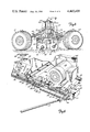
- FIG. 1 is a top plan view of a top unloading silo unloader of the invention located in a tower silo;
- FIG. 2 is an enlarged sectional view taken along the line 2--2 of FIG. 1;
- FIG. 3 is an enlarged sectional view taken along the line 3--3 of FIG. 2;
- FIG. 4 is an enlarged sectional view taken along the line 4--4 of FIG. 1;
- FIG. 5 is a plan view of the outer end of the collector of the silo unloader of FIG. 1;
- FIG. 6 is a sectional view taken along the line 6--6 of FIG. 5;
- FIG. 7 is an enlarged sectional view taken along the line 7--7 of FIG. 1;
- FIG. 8 is a perspective view of the inner end of the silo unloader of FIG. 1 showing the leveling actuator and controls therefor;
- FIG. 9 is an enlarged sectional view taken along the line 9--9 of FIG. 6;
- FIG. 10 is an enlarged foreshortened sectional view taken along the line 10--10 of FIG. 2.
- FIGS. 1 and 2 there is shown a tower silo indicated generally at 20 having an upright cylindrical wall 21 providing a cylindrical storage chamber or material storage area for accommodating bulk feed materials 26, as silage, haylage, grains, and the like. Other types of particulate materials can be stored in silo 20.
- Wall 21 has a plurality of vertically aligned openings or doorways 22 providing access between the interior of silo 20 and an upright generally U-shaped chute 23.
- Chute 23 is an upright member attached to the outside of wall 21 providing an upright passage 24 in communication with doorways 22, so that material moved through an open doorway 22 will fall to the base of silo 20.
- Conveyor structures are used to move the material from the base of the silo to bulk feeders, vehicles, or the like.
- a top unloading silo unloader indicated generally at 27 is operable to remove material from the top and discharge the material through doorway 22 into passage 24.
- Top unloading silo unloader 27 has a collector 28 operable to move around silo wall 21 and transport the material to the center area of the silo.
- An impeller 29 throws the material through a discharge chute 31 directed toward the open doorway 22.
- Unloader 27 has a pair of generally parallel frame members 32 and 33, such as elongated tubular beams.
- the frame members 32 and 33 extend outwardly generally parallel to each other toward wall 21 to form part of the material collector 28.
- Collector 28 has an elongated forward auger 34 located below frame members 32 and 33.
- Auger 34 has an elongated shaft 36 carrying a first spiral flight 37 extended from the wall toward impeller 29.
- the inner end of shaft 36 is connected to a gear box 41 mounted on frame members 32 and 33.
- a second reverse helical flight 38 is located adjacent the inner end of impeller 29.
- Generally radial paddles 39 secured to shaft 36 are located between the flights 37 and 38. As shown in FIG.
- outer end of shaft 36 is rotatably mounted in a bearing 44 retained in a generally upright leg 43 attached to a horizontal plate 42.
- a rear or trailing auger indicated generally at 46 in FIG. 7, has a horizontal shaft 47 secured at its inner end to an output shaft 48 of gear box 41.
- a first helical flight 49 secured to shaft 47 extends from impeller 29 to the outer end of the collector 28. Flight 49 on rotation of the auger 46 moves the material inwardly in the direction of arrow 50.
- Reverse helical flights 51 are secured to shaft 47 adjacent the rear side of impeller 29. On rotation of shaft 47, the reverse helical flights 51 prevent material from passing impeller 29 in the direction of arrow 52 to function as a moving shield keeping the material from collecting behind impeller 29.
- Flights 51 are preferably four 1/4 turn flights longitudinally spaced on shaft 47. Portions of adjacent flights overlap.
- the outer end of shaft 47 is rotatably mounted in a bearing 53 secured to a lower end of a generally upright leg 54.
- Leg 54 is attached to horizontal plate 42.
- a plate 55 secured to frame member 33 is located behind auger 46.
- Wall cleaning wheels 56 and 57 are secured to the outer ends of auger shafts 36 and 46 outwardly of arms 43 and 54, respectively.
- Wall cleaning wheels 56 and 57 are located in contiguous relationship relative to the inside surface of wall 21 and rotate with augers 34 and 46.
- Wall cleaning wheels 56 and 57 function to chip and clean any material, such as frozen material, that may adhere to the inside of wall 21.
- Wall cleaning wheels or rotatable cleaners 56 and 57 are spaced from the inside of wall 22 by a pair of generally horizontal wheels 66 and 68.
- Upright axle 67 secured to plate 42 rotatably supports wheel 66.
- a second upright axle 69 secured plate 42 rotatably mounts wheel 68.
- Adjustable assemblies 216 and 217, shown in FIG. 10, provide radial adjustment for wheels 66 and 68 thereby adjusting the wall clearance of wall cleaners 56 and 57.
- plate 42 extends over the top of the outer end of frame members 32 and 33.
- a pad 61 secured to frame member 33 is connected with a nut and bolt assembly to plate 42.
- a similar pad 63 is secured to frame member 32 and is attached with a nut and bolt assembly 64 to plates 42.
- an open auger guard indicated generally at 71 is located over augers 34 and 46.
- the auger guard 71 comprises a plurality of laterally spaced longitudinal members 72 located between and generally parallel to frame members 32 and 33.
- the inner end of the members 72 is secured to a cross end member 73.
- the outer end of tubular members 72 is secured to a cross end member 74.
- Members 72 may be elongated tubular members.
- opposite ends of cross member 73 are secured to inwardly directed ears 76 and 78 secured to frame members 32 and 33, respectively.
- Nut and bolt assemblies 77 and 79 secure the member 73 to ears 76 and 78.
- Nut and bolt assemblies 81 and 82 shown in FIG. 4, secure the cross end member 74 to ears (not shown) secured to frame members 32 and 33.
- Impeller 29 has a scroll shaped impeller housing 83 having a side inlet opening 84. As shown in FIG. 2, opening 84 is located adjacent the inner end of helical flight 37 and leading auger 34 and adjacent paddles 39. Housing 83 rotatably supports a transverse shaft 86. An impeller having a plurality of pivotally mounted paddles is located within the housing. An example of the details of the impeller is disclosed by Hansen in U.S. Pat. No. 3,589,500. Impeller housing 83 has an upwardly directed outlet or neck 87 connected to a transition assembly 88. The transition assembly is a slip ring assembly having a non-rotatable part carrying a rotatable member.
- the non-rotatable part and rotatable member each have a central passageway allowing the material to move by the rotating impeller into an out chute 91.
- slip ring assemblies are shown in U.S. Pat. Nos. 3,517,369 and 3,594,680.
- a pivot 92 pivotally mounts the out chute on transition assembly 88.
- out chute 91 extends in a generally radial direction and has an outer end 93 spaced from the wall 92 and aligned with an open doorway 22.
- a torque arm 94 is pivotally mounted on the non-rotating part of the transition assembly 88 and extends outwardly through the open doorway 22.
- a generally upright rigid link 96 connects torque arm 94 to out chute 91 to hold the out chute in operative relation relative to torque arm 94 and in alignment with open doorway 22.
- a triangular frame assembly indicated generally at 97 is attached to the lower side of the non-rotatable member of slip ring 88.
- Frame assembly 97 has three angle members located about slip ring 88 in a triangular arrangement. Each angle member has an outer end attached to a cable 98.
- the upper ends of cable 98 are secured to a ring 99 connected to an elongated cable 101.
- Cable 101 is trained over a pulley 102 connected to a support mounted on the top of the silo wall 21 to pendently support the center portion of the silo unloader in the silo. Cable 101 extends from pulley 102 to a winch (not shown) secured to the outside adjacent the base of silo 20.
- the support 103 can be a frame structure on top of the silo wall or a tripod mounted on wall 21. Examples of tripod structure are shown in U.S. Pat. Nos. 3,128,081 and 3,211,407.
- an outwardly directed generally horizontal arm 104 is secured to the inner end of frame member 32 adjacent impeller 29.
- a guide wheel 105 is rotatably mounted for rotation about a generally upright axis on the outer end of arm 104. Wheel 105 engages the inside of wall 21.
- a brace 107 is secured to the inner end of frame member 32 and engages the mid-portion of arm 104. Arm 104 is located approximately 90 degrees in front of collector 28.
- Collector 28 is moved around the silo in the direction of the arrow 108 with a pair of power driven drive wheels 109 and 111.
- wheel 109 has a horizontal rotating axle 112 rotatably mounted in a bearing 113.
- a plate 114 secured to a forward end of a walking beam or rocker arm 116 is connected with nut and bolt assemblies 117 to bearing 113.
- Wheel 111 has a rotating axle 118 rotatably mounted in a bearing 119.
- Bearing 119 is secured to a plate 121 with nut and bolt assemblies 120.
- Nut and bolt assemblies 117 and 120 permit the angle of wheels 109 and 111 relative to wall 21 to be adjusted about upright axes.
- Plate 121 is attached to the rear end of beam 116.
- a generally horizontal sleeve 122 is attached to the mid-portion of beam 116.
- Sleeve 122 is rotatably mounted on a tubular member or lifting pipe arm 123 extended along the top of collector 28.
- the inner end of member 123 is pivotally connected to impeller housing 83 with a pair of upright ears 124 and transverse pivot pin 126.
- the ears 124 are secured to housing 83.
- Pivot pin 126 allows the member 123 to pivot about a generally horizontal axis, whereby wheels 109 and 111 are continuously located in driving engagement with the top surface of material 26. Drive wheels 109 and 111 are not lifted off the material 26 by collector 28 or impeller 29.
- a power transmission or gear box 127 is mounted on frame members 32 and 33 adjacent the front side of impeller housing 83. The weight of gear box 127 is transmitted to collector 28, as gear box 127 is located outwardly from the cable 101.
- Gear box 127 has a pair of outwardly directed drive shafts 128 and 129.
- a first drive shaft 131 having universal joints 132 and 133 at the opposite ends thereof drivably connects shaft 128 to wheel axle 112.
- a second drive shaft having universal joints 136 and 137 at the opposite ends thereof drivably connects gear box shaft 129 with wheel axle 118.
- the drive shafts 131 and 134 concurrently rotate wheels 109 and 111 to move collector 28 around the silo wall in the direction of arrow 108.
- a motor 139 as an electric motor, is attached to a mount, indicated generally at 141, which is adjustably supported on the inner ends of frame members 32 and 33.
- the mount 141 comprises pairs of sleeves 142 and 143 positioned about the cylindrical frame members 32 and 33.
- Cross members 144 and 146 extend between and are secured to sleeves 142 and 143.
- a pair of rods 147 are secured to sleeves 142 and extend through a hole in an upright ear 149 fixed to frame members 32 and 33.
- Nuts 148 threaded onto the rods 147 are used to adjust the longitudinal position of mount 141 relative to frame members 32 and 33 to adjust the tension on the drive belts associated with the drive pulleys of the motor.
- motor 139 has a drive shaft 151 carrying a pulley 152.
- An endless belt 153 trained about pulley 152 surrounds a large driven pulley 154 mounted on the impeller shaft 86.
- a second belt 156 is trained about a second pulley 155 on motor drive shaft 151.
- Belt 156 is located about a pulley 158 mounted on the input power shaft of the gear box 41.
- the power is transmitted from impeller shaft 86 to gear box 127 through a pulley 159 mounted on shaft 86 and a belt 161 operatively connecting pulley 159 to a large pulley 162 mounted on the input shaft 163 of gear box 127.
- gear box 41 On operation of motor 139, gear box 41, impeller drive shaft 86, and the gear box 127 are concurrently operated, whereby the leading and trailing augers 34 and 46 are rotated about their longitudinal axes, the impeller in housing 83 is rotated to throw material into out chute 91 and drive wheels 109 and 111 are rotated to power collector 28 in the direction of arrow 108. As shown in FIGS. 1 and 8, all of the belt and pulley drive structure is located under a shield 164.
- Unit 166 is a linear actuator that is mounted in a generally horizontal sleeve 167 attached to a transverse cross member 168 secured to the inner ends of the frame members 32 and 33.
- Linear actuator 166 has a reversible D.C. motor 169 operable to selectively move an actuator rod 171 in opposite longitudinal directions.
- Linear actuator 166 has the details of linear actuator 113 disclosed in U.S. Pat. No. 4,170,385.
- the linear actuator 113 of U.S. Pat. No. 4,170,385 is incorporated herein by reference.
- the outer end of actuator rod 171 is attached to a block 172.
- a flexible power transmitting line or cable 173 secured to block 172 extends over collector 28 to a pulley 174, shown in FIG. 6.
- a U-shaped bracket 176 secured to the center of plate 42 carries a pivot bolt 177 for rotatably mounting pulley 174 on bracket 176.
- Cable 173 extends upwardly from pulley 174 to an outwardly directed arm 178 attached to an inwardly projected cylindrical member or tube 179. Cable 173 has an enlarged portion, as a knot or clamp, in engagement with the top of arm 178.
- tube 179 projects into the outer end of tubular support 123 and is secured thereto with a nut and bolt assembly 181. Cylindrical member 179 is located between a pair of upright plates 182 and 183.
- the upper ends of plates 182 and 183 are connected together with a horizontal nut and bolt assembly 184.
- Nut and bolt assembly 184 laterally spaces plates 182 and 183 from each other to provide a vertical slot or opening 186 allowing plates 182 and 183 and horizontal support plate 42 to move up and down relative to beam 116.
- a plurality of nut and bolt assemblies 187 and 188 secure the lower ends of plates 182 and 183 to horizontal plate 42.
- linear actuator 166 has a control box 189 mounted adjacent motor 169 for controlling the operation of motor 169.
- a switch 191 operatively connected to control box 189 has a downwardly directed movable arm 192.
- the arm 192 moves from a vertical neutral position to left and right positions to control the forward and reverse operation of D.C. motor 169.
- the linear actuator 166, motor 169, control box 189, and switch 191 are mounted as a unit in sleeve 167 and U-shaped bracket 196 secured to frame member 32.
- motor 169 fits into bracket 196.
- a removable pin 197 in bracket 196 holds motor 169 in assembled relation with bracket 196.
- a horizontal linkage 193 is connected with a connector 194 to the lower end of arm 192.
- Linkage 193 extends forwardly to connector 195 pivotally mounted on the lower end of a link 209.
- Linkage 193 has a turn buckle 202 operable to selectively adjust the length of the linkage.
- Turn buckle 202 is used to adjust the cone or incline of the upper surface of the material 26 as a result of the operation of the collector 28.
- Block 172 attached to the longitudinal movable actuator 171 carries a generally horizontal plate 203.
- a pair of upright ears or pins 204 and 206 are secured to and project upwardly from plate 203.
- the linkage 193 extends between the pins 204 and 206.
- Stop washers 207 and 208 mounted on linkage 103 are adapted to engage the pins 204 and 206 to provide limits to the longitudinal movement of linkage 193 and operation of the linear actuator.
- Link 209 is secured to a fixed arm 211 with a spring bias bolt 212.
- Arm 211 is attached to a rotating non-pivoting portion of the transition assembly 88 so that link 209 moves in a circular path along collector 28.
- Arm 211 is secured to the bottom of a rotating non-pivoting portion of transition assembly 88.
- An example of the rotating non-pivoting portion of a top silo unloader transition assembly is shown at 154 in FIGS. 9 and 10 of U.S. Pat. No. 4,170,385.
- Link 209 and arm 211 are fixed reference means, as they do not move up and down with collector 28 as it moves around the silo.
- the up and down movements of collector 28 relative to the non-pivoting reference or link 209 causes linkage 193 to move in opposite longitudinal directions, indicated by arrows 214, thereby moving the switch arm between its neutral and on positions.
- wall wheel adjusting assemblies 216 and 217 operable to allow radial adjustment of wheels 66 and 68 and hold the wheels in their adjusted positions.
- the clearance of wall cleaners 56 and 57 relative to wall 21 is determined by the wall engaging wheels 66 and 67. This clearance is adjusted by changing the radial mounting locations of the wheel axles 66 and 67.
- wheel adjusting assembly 216 has a flat bar 218 located on top of plate 42. The outer end of bar 218 has a hole 219 for axle 67. The lower end of axle 67 extends through a radial slot 221 in plate 42.
- the inner end of bar 218 has a radial slot aligned with a hole in plate 42 for a nut and bolt assembly 226.
- An upright shoulder or transverse rib 223 is secured to the upper side of the midsection of bar 218.
- a circular disc 224 having an off-center hole 225, is located in engagement with bar 218, with a portion of the outer edge of disc 224 in engagement with shoulder 223.
- the bolt of nut and bolt assembly 226 extends through off-center hole 225 and the nut thereof clamps the disc in an adjusted position.
- Wheel adjusting assembly 217 has the same structure as adjusting assembly 216, identified with the same reference numbers, with the suffix A.
Abstract
Description
Claims (53)
Priority Applications (1)
| Application Number | Priority Date | Filing Date | Title |
|---|---|---|---|
| US06/343,024 US4465409A (en) | 1982-01-27 | 1982-01-27 | Silo unloader |
Applications Claiming Priority (1)
| Application Number | Priority Date | Filing Date | Title |
|---|---|---|---|
| US06/343,024 US4465409A (en) | 1982-01-27 | 1982-01-27 | Silo unloader |
Publications (1)
| Publication Number | Publication Date |
|---|---|
| US4465409A true US4465409A (en) | 1984-08-14 |
Family
ID=23344355
Family Applications (1)
| Application Number | Title | Priority Date | Filing Date |
|---|---|---|---|
| US06/343,024 Expired - Fee Related US4465409A (en) | 1982-01-27 | 1982-01-27 | Silo unloader |
Country Status (1)
| Country | Link |
|---|---|
| US (1) | US4465409A (en) |
Cited By (3)
| Publication number | Priority date | Publication date | Assignee | Title |
|---|---|---|---|---|
| US5954915A (en) * | 1996-05-24 | 1999-09-21 | Voorwood Company | Surface finishing apparatus |
| US20040159056A1 (en) * | 2003-02-13 | 2004-08-19 | Hedrick Thomas W. | Bulk material storage facilities with access chases and/or internal filling structures |
| US20160304297A1 (en) * | 2015-04-15 | 2016-10-20 | Marvin B. Zimmerman | Top Mounted Silo Unloader with Belt Conveyor Discharge |
Citations (6)
| Publication number | Priority date | Publication date | Assignee | Title |
|---|---|---|---|---|
| US2995260A (en) * | 1956-02-20 | 1961-08-08 | Vandale Corp | Unloading apparatus |
| US3090506A (en) * | 1960-07-21 | 1963-05-21 | Vandale Corp | Leveling structure |
| US3223256A (en) * | 1958-12-24 | 1965-12-14 | Vandale Corp | Silo unloader structure |
| US3301412A (en) * | 1965-03-11 | 1967-01-31 | Vandale Corp | Closure structure for silo unloader collector arm |
| US4170385A (en) * | 1977-01-14 | 1979-10-09 | Veda, Inc. | Silo unloader with leveling and drive structure |
| US4329105A (en) * | 1979-04-30 | 1982-05-11 | Veda, Inc. | Silo unloader leveling apparatus |
-
1982
- 1982-01-27 US US06/343,024 patent/US4465409A/en not_active Expired - Fee Related
Patent Citations (6)
| Publication number | Priority date | Publication date | Assignee | Title |
|---|---|---|---|---|
| US2995260A (en) * | 1956-02-20 | 1961-08-08 | Vandale Corp | Unloading apparatus |
| US3223256A (en) * | 1958-12-24 | 1965-12-14 | Vandale Corp | Silo unloader structure |
| US3090506A (en) * | 1960-07-21 | 1963-05-21 | Vandale Corp | Leveling structure |
| US3301412A (en) * | 1965-03-11 | 1967-01-31 | Vandale Corp | Closure structure for silo unloader collector arm |
| US4170385A (en) * | 1977-01-14 | 1979-10-09 | Veda, Inc. | Silo unloader with leveling and drive structure |
| US4329105A (en) * | 1979-04-30 | 1982-05-11 | Veda, Inc. | Silo unloader leveling apparatus |
Cited By (9)
| Publication number | Priority date | Publication date | Assignee | Title |
|---|---|---|---|---|
| US5954915A (en) * | 1996-05-24 | 1999-09-21 | Voorwood Company | Surface finishing apparatus |
| US6234299B1 (en) | 1996-05-24 | 2001-05-22 | Voorwood Company | Surface finishing apparatus and method |
| US6536499B2 (en) | 1996-05-24 | 2003-03-25 | Voorwood Company | Surface finishing apparatus and method |
| US20040159056A1 (en) * | 2003-02-13 | 2004-08-19 | Hedrick Thomas W. | Bulk material storage facilities with access chases and/or internal filling structures |
| US7127854B2 (en) | 2003-02-13 | 2006-10-31 | Hedrick Thomas W | Bulk material storage facilities with access chases and/or internal filling structures |
| US20070056984A1 (en) * | 2003-02-13 | 2007-03-15 | Hedrick Thomas W | Bulk material storage facilities with access chases and/or internal filling structures |
| US7686545B2 (en) | 2003-02-13 | 2010-03-30 | Hedrick Thomas W | Bulk material storage facilities with access chases and/or internal filling structures |
| US20160304297A1 (en) * | 2015-04-15 | 2016-10-20 | Marvin B. Zimmerman | Top Mounted Silo Unloader with Belt Conveyor Discharge |
| US9908722B2 (en) * | 2015-04-15 | 2018-03-06 | Marvin B. Zimmerman | Top mounted silo unloader with belt conveyor discharge |
Similar Documents
| Publication | Publication Date | Title |
|---|---|---|
| US4329105A (en) | Silo unloader leveling apparatus | |
| US2601608A (en) | Grain unloader having a feed auger with an adjustable cover | |
| US3204786A (en) | Material handling apparatus | |
| RU2001135796A (en) | Method and assembly for harvesting | |
| US4117920A (en) | Auger hopper | |
| US4585385A (en) | Bottom unloader | |
| UA77387C2 (en) | Method and system for harvesting crops containing a cleaning mill (variants) with a graff receiver and a harvesting unit with a hitching arm | |
| WO2001058247A1 (en) | Offset auger feed for a combine clean grain elevator | |
| AU2018256514B2 (en) | Nut collector | |
| US2870594A (en) | Nut gatherer | |
| US4085570A (en) | Forage harvester and attachment therefor | |
| US4198186A (en) | Silo dig out tool | |
| US5468187A (en) | Peanut cleaner | |
| US4465409A (en) | Silo unloader | |
| US3626677A (en) | Mechanical harvester | |
| US3901008A (en) | Crop gathering apparatus | |
| US9908722B2 (en) | Top mounted silo unloader with belt conveyor discharge | |
| US4170385A (en) | Silo unloader with leveling and drive structure | |
| US5099984A (en) | Telescopic auger | |
| US5039273A (en) | Conveyor system for a container | |
| US3221483A (en) | Rotary lawn tool with gathering means | |
| US7093707B2 (en) | Grain harvester multi-angular inclined delivery conveyor and drive | |
| US4345655A (en) | Rock picker with storage conveyors | |
| US3171241A (en) | Cotton picker | |
| US4772173A (en) | Silo unloader |
Legal Events
| Date | Code | Title | Description |
|---|---|---|---|
| AS | Assignment |
Owner name: VEDA, INC. BOX 115, LONG LAKE, MN 55356 A CORP. Free format text: ASSIGNMENT OF ASSIGNORS INTEREST.;ASSIGNORS:BUSCHBOM, FLOYD E.;HANSEN, GLEN D.;REEL/FRAME:003966/0375 Effective date: 19820120 |
|
| REMI | Maintenance fee reminder mailed | ||
| LAPS | Lapse for failure to pay maintenance fees | ||
| STCH | Information on status: patent discontinuation |
Free format text: PATENT EXPIRED DUE TO NONPAYMENT OF MAINTENANCE FEES UNDER 37 CFR 1.362 |
|
| FP | Lapsed due to failure to pay maintenance fee |
Effective date: 19880814 |
|
| AS | Assignment |
Owner name: VAN DALE COMPANIES, INC. Free format text: MERGER;ASSIGNOR:VEDA, INC.;REEL/FRAME:005224/0015 Effective date: 19840430 Owner name: VCI CAPITAL, INC. Free format text: CHANGE OF NAME;ASSIGNOR:VAN DALE COMPANIES, INC., A MN CORP.;REEL/FRAME:005224/0022 Effective date: 19861015 |