US4475666A - Automated liquid dispenser control - Google Patents
Automated liquid dispenser control Download PDFInfo
- Publication number
- US4475666A US4475666A US06/297,956 US29795681A US4475666A US 4475666 A US4475666 A US 4475666A US 29795681 A US29795681 A US 29795681A US 4475666 A US4475666 A US 4475666A
- Authority
- US
- United States
- Prior art keywords
- piston
- syringe
- microprocessor
- lead
- velocity
- Prior art date
- Legal status (The legal status is an assumption and is not a legal conclusion. Google has not performed a legal analysis and makes no representation as to the accuracy of the status listed.)
- Expired - Lifetime
Links
Images


Classifications
-
- B—PERFORMING OPERATIONS; TRANSPORTING
- B01—PHYSICAL OR CHEMICAL PROCESSES OR APPARATUS IN GENERAL
- B01L—CHEMICAL OR PHYSICAL LABORATORY APPARATUS FOR GENERAL USE
- B01L3/00—Containers or dishes for laboratory use, e.g. laboratory glassware; Droppers
- B01L3/02—Burettes; Pipettes
- B01L3/021—Pipettes, i.e. with only one conduit for withdrawing and redistributing liquids
Definitions
- This invention relates generally to automated liquid dispensers and more particularly to electronic control for a bench-top laboratory instrument which employs one or more easily demountable precision metering syringes reciprocated in response to a programmed microprocessor or computer control for selectively dispensing reagent or diluting samples with reagent and other common normally manual laboratory procedures.
- One object of the invention is to provide a precision laboratory instrument for automating many common normally manual liquid handling laboratory procedures with improved accuracy, precision, speed and reproducibility.
- Another object of the invention is to provide a liquid dispensing apparatus capable of local microprocessor or remote computer control.
- One other object is to provide precise servo control for each syringe which is responsive to its piston velocity, direction and position and compensates for mechanical backlash.
- Still another object of the invention is a simple valve actuator and control for a plastic valve having planar seating faces which minimizes face wear.
- FIG. 1 is an overall perspective view of the liquid dispenser with dual syringes
- FIG. 2 is a partial perspective view illustrating a typical metering syringe and the actuator and valve means for it;
- FIG. 2A is an elevational view of the position detector disc configuration shown in FIG. 2;
- FIG. 3 is a vertical cross-sectional view of the instrument taken along line 3--3 of FIG. 1;
- FIG. 4 is a plan view of one form of keyboard for the instrument taken along line 4--4 of FIG. 3.
- FIG. 5 is vertical sectional view of the lead-screw drive for one syringe actuator taken along line 5--5 of FIG. 1;
- FIG. 6 is a top view of the lead-screw nut and its clamping arrangement taken along line 6--6 of FIG. 5;
- FIG. 7 is an exploded view of the internal lead-screw drive for each syringe actuator
- FIG. 8 is a vertical sectional view of the valve means for each syringe taken along line 8--8 of FIG. 1;
- FIG. 9 is a plan view partly in section of the valve means and valve actuator taken along line 9--9 of FIG. 8;
- FIG. 10 is a vertical, partially sectional view of the valve means taken along line 10--10 of FIG. 8;
- FIG. 11 is an exploded view of the valve means and valve actuator for each metering syringe
- FIG. 12 illustrates the valving configuration for a dispenser with two syringes as shown in FIG. 1;
- FIG. 13 illustrates the valving arrangement for a dispenser with three syringes for example
- FIG. 14 is a vertical sectional view of a small bore syringe used in the instrument.
- FIG. 15 is a vertical sectional view of a large bore syringe used in the instrument.
- FIG. 16 is an exploded view of the metering syringe components
- FIG. 17 is an overall perspective view of the liquid dispenser with a single syringe
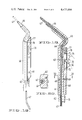
- FIG. 18 is an enlarged perspective view of the probe illustrated in FIGS. 1 and 17;
- FIG. 19 is a cross-sectional view of the probe showing its internal construction
- FIG. 20 is a cross-sectional view of the probe taken along line 20--20 of FIG. 19;
- FIG. 21 is a schematic block diagram of the microprocessor control and other electronics for the illustrated dispenser.
- the instrument illustrated in FIG. 1 is designed for actuation of two precision metering syringes.
- the invention also is useful in the form of a single syringe shown in FIG. 17 or more than two syringes with appropriate valving and actuator changes which will be apparent from a consideration of the following description.
- the illustrated instrument includes one or more precision metering syringes 1 arranged for drawing sample by means of probe 2 from a test tube 3, for example, or for dispensing sample or reagent-diluted sample into test tube 3', shown in hidden lines in FIGS. 1 and 17.
- the instrument is capable of withdrawing reagent from a reservoir, such as from beaker 4, and then using it to dilute a sample or otherwise to be dispensed from the probe 2.
- Each metering syringe 1 mounts upon a syringe actuator, referred to generally as 5, in FIG. 2 at its rod end and is in fluid-tight communication with valve means 6 in FIG. 2.
- the syringe actuator 5, valve means 6 and its valve actuator, referred to generally as 7, mount upon a rigid frame 8.
- a housing 9 of chemical resistent material encloses the working components of the instrument apart from the metering syringes which are open for observation and ease of removal and replacement.
- a keyboard 10 for local microprocessor control mounts on the housing 9 on the front of the instrument adjacent to the metering syringes.
- Each metering syringe as is more particularly shown in FIGS. 14-16, comprises a precision ground glass cylinder 15 and a piston 17 carried on a piston rod 16 reciprocable within the cylinder.
- a connecting flange and seat 18 seals upon the blind end of the cylinder.
- the seat fits within a recess in the valve means 6 that mounts upon the frame 8.
- the connecting flange 18 is clamped to the valve means 6 by clamp 22 and set-screw 23.
- the end of the piston rod 16 remote from piston 17 carries a mounting flange 19 made from magnetic material.
- the mounting flange 19 carries on its periphery an o-ring 20 with which to secure to the flange a centering sleeve 21.
- the centering sleeve centers the mounting flange 19 upon the end of an externally threaded lead-screw nut 25 over which the sleeve fits.
- the nut 25 carries a permanent magnet 26 which holds the flange 19 of magnetic material firmly to the top of the lead-screw nut centered thereon by sleeve 21.
- the sleeve 21 sealed by o-ring 20 to mounting flange 19 also functions as an open reservoir to contain leaks or provide spill protection should a fragile glass syringe break, or fracture.
- the external thread 27 on the lead-screw nut 25 threads upon corresponding threads 28 formed on the internal surface of lead-screw sleeve 29 which is rotably mounted in ball bearings 30 upon frame 8.
- the sleeve 29 is rotated by a toothed belt gear 31 and drive belt 32 by servo motor drive means 33 shown in FIG. 2.
- the lead-screw nut 25 is restrained from rotation relative to this sleeve 29 by the pair of brackets 34 mounted at one end upon the frame 8 as shown in FIG. 7 and passing through slots 35 formed in the lead-screw nut 25.
- the brackets are secured at the bottom ends also to the frame 8 by means of a slotted plate 36 which fits over the free end of each bracket and is screwed to the frame as is illustrated in FIG. 5.
- each metering syringe mounted in fluid communication with the blind end of each metering syringe is more particularly shown in FIGS. 8-11.
- Each includes a valve body 40 having a generally planar valve seat 41 bored with four ports 42, 43, 44 and 45 as illustrated in FIG. 10.
- the illustrated ports are in diametrically opposed pairs and each is equidistant from the rotational axis of a mating rotor 46.
- the spring-loaded rotor 46 has a replaceable seating face 47 having a fluid communication groove 48 on its valving face which communicates pairs of the ports 42,44 or 43,45 with one another in a programmed selection sequence by valve actuator means 7.
- the valve actuator may be a gearhead motor or the illustrated drive motor 49 geared to a drive shaft 50 that is biased by spring 51, ball 52 and sleeve 53 against the rotor 46 to hold the rotor in fluid-tight seating relationship with the valve seat 41.
- the pin 54 carried on drive shaft 50 mates with a recess 55 in the sleeve 53 and pin 56 on the sleeve mates with recess 57 in rotor 46 to enable the actuator means 7 to rotate the groove 48 into selected communication among the valve port pairs 42,44 or 43,45.
- the hand held probe 2 may carry electrical switches for actuating the delivery and aspiration cycles by energizing the valve actuator 7.
- the probe also may include indicating means showing the instantaneous status of the sequential mode of operation.
- the probe handle clamps to chemically inert tubing communicating it with the valve means 6 for one or several of the metering syringes.
- the tubing is bundled with electric conductors connecting the probe switches, microprocessor and valve actuating means.
- the particular hand-held probe 2 illustrated in FIGS. 1 and 17 is shown in more detail in FIGS. 18-20.
- It comprises a handle 60 formed of an elongated bar of tubular or rectangular cross-section material, such as plastic, having a longitudinal circular bore 61 in the embodiment shown.
- a tube holder 62 fits within the bore preferrably in an interference fit.
- the tube holder is generally tubular in shape with internal bore 63 and at the one end has a goose-neck configuration with a pair of reverse curves 64, 65.
- the tube holder 62 ends beyond the goose-neck in a nose portion 66.
- Ther tube holder 62 carries within it Teflon flexible pipette tubing 67 frequently used in pipetting which communicates with the valve means 6.
- the tubing 67 trains through the internal bore 63 of holder 62.
- the reverse curves at 64 and 65 provide interference or frictional engagement of the tubing 67 against the interior walls of the bore 63 and hold the tubing 67 firmly within tube holder 62 during normal operation.
- tubing 67 can easily be replaced by pulling it out of the tube holder and inserting another piece of Teflon pipette tubing.
- the tube holder may be secured within handle 60 by an annular groove 68 around its periphery and a set screw 69 as shown in FIG. 20. This arrangement permits the operator to twist the tube holder within handle 60 to provide any 360° orientation for the nose portion 66 as the operator sees fit. The interference fit holds the selected orientation.
- a pair of pressure switches 71, 72 mount in handle 60 adjacent to a push button 73 pivoted at 74 by the pressure of the thumb 75 of the operator into contact with one or the other of pressure switches 71,72.
- Appropriate electrical conductors 76 connect the probe switches 71,72 to the microprocessor and electronic valve acuating means mounted on the dispenser frame.
- the probe 2 also may include indicating means such as light emitting diodes 77,78 to indicate the instantaneous state of the dispener's sequential mode of operation. For example, LED 77 may light to indicate that the probe is ready to dispense sample or reagent and/or LED 78 may light to indicate the probe is ready to draw in sample or reagent.
- Operation of the illustrated dispenser is automated by a local microprocessor control using keyboard 10.
- the dispenser operation also can be controlled by a programmed remote computer or a local preprogrammed ROM cartridge for specific dedicated service.
- the computers control the stroke and speed and sense the instantaneous position of each piston 17 in the metering syringes so that those parameters can be varied upon a command inputed through the keyboard 10 or remote computer interface.
- Various modes of operation may be selected and preprogrammed into the illustrated microprocessor including the basic liquid transfers of drawing fluid into each syringe from the reagent reservoir, dispensing fluid from the syringe into the reagent reservoir, drawing fluid into the syringe from the sample probe tubing or dispensing fluid from the syringe into the sample probe tubing.
- Various modes of operation are obtainable including a dispense mode wherein a measured volume of liquid is drawn into a syringe from the reagent reservoir and then dispensed.
- a measured volume of liquid is drawn from the reagent reservoir and then one or more separate samples are aspirated into the sample probe tubing with air gaps separating one sample from another and from the reagent. Then the total content of the syringe may be dispensed back out through the sample probe tubing.
- Various wash, purge and other modes can also be programmed into the microprocessor.
- the microprocessor and electronic control for the described dispenser is illustrated schematically in FIG. 21. It includes microprocessor 80 with power supply 81.
- a bi-directional system bus 82 interconnects the microprocessor 80 with a random access memory 83, a programmed memory 84, bit input-output circuitry 85 for the probe switches, valve actuator and syringe actuator and interconnects an internal timer 86.
- a hybrid servo control circuit 87 is provided for each syringe motor 33.
- Keyboard-display interface circuitry 88 connects the keyboard and display 10 to the microprocessor 80 and has audible alarm 89.
- the system bus 82 also may interconnect the microprocessor 80 with a universal synchronous/asynchronous receiver transmitter (USART) and interface circuit 90 for connection with other devices such as an external computer control of perhaps a local preprogrammed cartridge memory for dedicated service.
- USBART universal synchronous/asynchronous receiver transmitter
- Each servo control circuit 87 is responsive to syringe piston velocity, direction and position and accurately positions, relative to one another, the lead-screw nut 25 and lead-screw sleeve 29 which drive each piston rod 16 as illustrated in FIG. 5.
- the hybrid servo system shown in FIG. 21 includes the bi-directional variable speed DC servo motor 33 shown in FIGS. 2, 3.
- a shaft encoder 91 which by reference to FIG. 2, includes slotted disc 92 on the motor shaft and a pair of optoelectric sensing means 93,94 arranged in phase quadrature that sense the presence of the one-hundred-fifty-five equally spaced slots 95 on disc 92.
- Each opto-electric sensing means can be a light coupled LED and a corresponding phototransistor, for example, to digitally encode syringe piston position, direction of movement and velocity as the rotating disc 92 interrupts the coupling.
- the encoder 91 supplies two trains of pulses in phase quadrature to tachometer converter 96 to control velocity and direction of motor rotation.
- the encoder 91 also supplies the pulses to position counter 97. It accumulates the pulse count the total of which is representative of the instantaneous piston location from a "home" position.
- the tachometer converter 96 and a velocity control DAC 99 each supply an analog output to error amplifier 98 which operates in velocity or position mode. Its output adjusts velocity and position by driving a pulse-width modulation motor driver 99a for the variable speed DC motor 33.
- the microprocessor 80 controls the hybrid servo 87 with eight output lines and receives information from the servo with five input lines.
- Five of the microprocessor output lines at 100 comprise a five-bit velocity command to DAC 99 of the servo which converts this command to a command analog current.
- the other output line at 100 selects the sign of the velocity command to control polarity of the motor driver 99a and, thus, the direction of motor rotation.
- Another output line at 101 selects the velocity or position mode for servo operation.
- Another output line, not shown, acts as a chip enable for the servo motor driver 99a.
- Four of the input lines at 102 comprise a four-bit position word input to the microprocessor from the position counter 97.
- a fifth microprocessor input line 103 is the home position sensor input which indicates that the syringe piston 17 is at "zero" volume or its "home” position within cylinder 15.
- the hybrid servo system can operate in two modes, i.e. a velocity mode or position mode.
- the servo starts out in velocity mode as the microprocessor outputs an increasingly larger five-bit velocity command word to the velocity digital-to-analog converter 99 along with a directional sign bit at 100.
- the time between successive velocity commands is variable to provide a variable acceleration characteristic in the converter output voltage. This parameter is keyed to various other system parameters such as currently programmed speed, current syringe size, probe tip size and fluid viscosity.
- the servo responds by accelerating syringe motor 33 to the commanded velocity and in the programmed direction.
- the position counter 97 While the motor 33 is in motion the position counter 97 accumulates counts and is periodically polled by the microprocessor 80. In this way the microprocessor keeps track of the instantaneous position of the piston 17, lead screw nut 25 and sleeve 29. As components approach their desired destination, the microprocessor causes the syringe motor 33 to decelerate by outputing successively smaller command words to DAC 99. The point at which each command outputs is determined by a variable lookup table in the software. Each entry in the table represents the number of position counts remaining in the current stroke and the position in the table represents the velocity DAC command appropriate for that number of counts to be sent to DAC 99. The microprocessor periodically compares the number of counts remaining with the table entry for the current velocity DAC command.
- the velocity DAC command is not changed. If the table entry is greater than or equal to the number of position counts remaining, the velocity DAC word is decremented by one and a comparison is made with the next table entry until one is found which is less than the number of counts. This process is then repeated until the piston terminal position is reached.
- This strategy controls piston velocity to optimize liquid delivery performance by minimizing undesirable effects such as liquid cavitation, frothing, splashing and denaturation.
- the microprocessor When the piston and lead-screw elements reach their desired position the microprocessor outputs a zero velocity word and switches the servo to position mode. This stops the syringe motor and locks it in place with an electronic detenting action. Should the encoder 91 supply a pulse to tachometer converter 96 in this position mode, error amplifier 98 is directed to supply a countering output to hold the piston position.
- the "soft home” detector 104 for the described dispenser includes another optically-coupled LED-phototransistor sensor 112 shown in FIGS. 6,7 which has its optical coupling interrupted by flag 113 mounted upon a flexure 114 secured to the frame 8 at the "soft home” position when abutment screw 115 on the lead-screw nut 25 moves the flag 113 upwardly to interrupt the optical coupling.
- the screw 115 permits adjustment of a precise "soft home” position short of the absolute or “hard” end of the piston stroke.
- the valve motor 49 may be a permanent magnet synchronous motor drive in one direction with AC current from a secondary winding of the power transformer in power supply 81. It is controlled by the microprocessor 80 through opto-electric valve position encoder 105 and a triac.
- the valve position encoder 105 consists of a pair of sensors that are optically-coupled light emitting diodes and phototransistors 106 shown in FIGS. 2 and 3. They sense the presence of one of two differently positioned sets of slots 107, 108 on disc 109 that is attached to the drive saft 50 for valve rotor 46. One set of slots is on the disc periphery in one diametrically opposed pair, as at 107 shown in FIG.
- valve controller 110 that interfaces with microprocessor 80.
- the microprocessor 80 turns on valve motor 49, which rotates the valve rotor 46 in one direction, and then polls the status of the valve position detector until the desired valve position is reached.
- the operator initially presses the mode key and then may select one of the modes on the other keys by pressing for example, the dispense, pipette, transfer, etc. key to select the desired mode. If the dispense mode has been selected, the letters DP appear in the "mode” display and the current value for the amount of reagent to be dispensed appears in the "reagent" display. The operator may press the "enter” button to accept the displayed regent quantity or enter a new value in RAM 83 by depressing appropriate numeric keys and then entering its value which also appears on the "reagent” display. Upon entering the new value, the indicator LED 78 for intake on the probe 2 is energized and the displayed amount of reagent then can be drawn into the syringe by pressing the push button 73 on the probe to actuate switch 72.
- the microprocessor then enables the syringe actuator motor 33 in the down stroke direction. Its speed is accelerated in accord with the program stored in ROM 84 relative to instantaneous stroke position accumulated in position counter 97. The measured volume of reagent is drawn into the syringe from the reagent vessel 4. The microprocessor decelerates and then stops the motor 33 at the selected stroke volume. The dispense LED 77 lights and depression of push button 73 to actuate switch 71 dispenses reagent to pipette tubing 67 at probe 2 with the piston 17 returning to the soft home position. The microprocessor disables the motor drive when that position is detected by the soft home detector 104.
- valve rotor 46 Corresponding positioning of valve rotor 46 is accomplished by the microprocessor to switch the fluid communicating groove 48, for example, to the intake position shown for the right-hand syringe of FIG. 12 to connect the syringe port 43 with reagent intake port 45 to draw reagent into the syringe.
- valve motor 49 switches the the groove 48 to communicate the syringe discharge port 42 to port 44 communicating with pipette tubing 67 as is shown in FIG. 13 for the righthand syringe.
- pipette and other modes can be similarly entered in the keyboard to draw in reagent as previously described.
- the operator selects a volume for each of the reagent and the desired number of samples by depressing the appropriate mode and digit keys and enters those values which appear in the reagent and sample displays along with a numeral to identify each particular sample.
- the microprocessor enables the motor drive 99a, the syringe draws in the entered amount of reagent and stops.
- the valve switches to dispense position and the piston moves down to draw an air gap into the end of tubing 67 from atmosphere to separate reagent from the first sample and the valve returns to intake position.
- the operator then places the probe in the sample reservoir, depresses the button 72,73 to draw sample into the probe.
- the operator repeats the sample take up for others that may be entered on the keyboard each time with an air gap between them.
- the operator then places the probe in position to dispense the entire contents of the pipette tubing and depresses the dispense button 71 to do so as described above.
Abstract
Description
______________________________________
microprocessor (80)
               Intel 8085
RAM (83), bit I/o (85)
               Intel 8156
and timer (86)
ROM (84)       Intel 2716 or 2732
keyboard/display (88)
               Intel 8279
USART (90)     Intel 8251A with RS232C inter-
               face
______________________________________
Claims (5)
Priority Applications (2)
| Application Number | Priority Date | Filing Date | Title |
|---|---|---|---|
| US06/297,956 US4475666A (en) | 1981-08-31 | 1981-08-31 | Automated liquid dispenser control |
| EP82106587A EP0070571A3 (en) | 1981-07-21 | 1982-07-21 | Automated liquid dispenser control |
Applications Claiming Priority (1)
| Application Number | Priority Date | Filing Date | Title |
|---|---|---|---|
| US06/297,956 US4475666A (en) | 1981-08-31 | 1981-08-31 | Automated liquid dispenser control |
Publications (1)
| Publication Number | Publication Date |
|---|---|
| US4475666A true US4475666A (en) | 1984-10-09 |
Family
ID=23148416
Family Applications (1)
| Application Number | Title | Priority Date | Filing Date |
|---|---|---|---|
| US06/297,956 Expired - Lifetime US4475666A (en) | 1981-07-21 | 1981-08-31 | Automated liquid dispenser control |
Country Status (1)
| Country | Link |
|---|---|
| US (1) | US4475666A (en) |
Cited By (127)
| Publication number | Priority date | Publication date | Assignee | Title |
|---|---|---|---|---|
| US4586546A (en) * | 1984-10-23 | 1986-05-06 | Cetus Corporation | Liquid handling device and method |
| WO1986002626A1 (en) * | 1984-10-23 | 1986-05-09 | Donald Earl Burg | Snap-in cartridge diluter |
| US4598840A (en) * | 1983-10-11 | 1986-07-08 | Burg Donald E | Snap-in cartridge diluter |
| US4633413A (en) * | 1983-07-28 | 1986-12-30 | Cavro Scientific Instruments | Digital dilution apparatus and method |
| US4634431A (en) * | 1976-11-12 | 1987-01-06 | Whitney Douglass G | Syringe injector |
| US4671123A (en) * | 1984-02-16 | 1987-06-09 | Rainin Instrument Co., Inc. | Methods and apparatus for pipetting and/or titrating liquids using a hand held self-contained automated pipette |
| US4702674A (en) * | 1985-10-04 | 1987-10-27 | Dosapro Milton Roy | Method of accurately setting the flow rate of a variable-flow metering pump, and a metering pump employing the method |
| US4702393A (en) * | 1985-02-07 | 1987-10-27 | Hyperion, Inc. | Compensating diluter/dispenser |
| US4718576A (en) * | 1985-12-23 | 1988-01-12 | Oximetrix, Inc. | Fluid infusion pumping apparatus |
| US4760939A (en) * | 1985-05-04 | 1988-08-02 | Jencons (Scientific) Limited | Liquid dosing device with digital display |
| US4790823A (en) * | 1986-02-14 | 1988-12-13 | Societe Civile De Recherches Mesalyse | Apparatus for injecting or withdrawing substances |
| US4812724A (en) * | 1984-11-13 | 1989-03-14 | Liebel-Flarsheim Corporation | Injector control |
| US4821586A (en) * | 1988-02-25 | 1989-04-18 | Medical Laboratory Automation, Inc. | Programmable pipette |
| US4854324A (en) * | 1984-01-31 | 1989-08-08 | Medrad, Inc. | Processor-controlled angiographic injector device |
| US4869397A (en) * | 1987-06-24 | 1989-09-26 | Liquipak International, Inc. | Adjustable fill motor assembly |
| US4883199A (en) * | 1987-07-28 | 1989-11-28 | Graco Inc. | Fluid dispensing device |
| US4921133A (en) * | 1987-11-06 | 1990-05-01 | Minnesota Mining And Manufacturing Company | Method and apparatus for precision pumping, ratioing and dispensing of work fluids |
| US4934564A (en) * | 1989-03-23 | 1990-06-19 | Eastman Kodak Company | Drop jet metering method and system |
| US4950134A (en) * | 1988-12-27 | 1990-08-21 | Cybor Corporation | Precision liquid dispenser |
| US4952205A (en) * | 1987-04-04 | 1990-08-28 | B. Braun Melsungen Ag | Pressure infusion device |
| US4957226A (en) * | 1987-06-05 | 1990-09-18 | Wells Manufacturing | Automatic food dispensing method, apparatus and utensil |
| US4964533A (en) * | 1985-03-18 | 1990-10-23 | Isco, Inc. | Pumping system |
| US4967606A (en) * | 1988-04-29 | 1990-11-06 | Caveo Scientific Instruments, Inc. | Method and apparatus for pipetting liquids |
| US4976161A (en) * | 1988-04-15 | 1990-12-11 | Przedsiebiorstwo Polonijno-Zagraniczne Plastomed | Fluid dispensing device |
| US4976696A (en) * | 1987-08-10 | 1990-12-11 | Becton, Dickinson And Company | Syringe pump and the like for delivering medication |
| US5012845A (en) * | 1988-08-18 | 1991-05-07 | Dynatech Precision Sampling Corporation | Fluid injector |
| US5027978A (en) * | 1989-08-24 | 1991-07-02 | Minnesota Mining And Manufacturing Company | Method and apparatus for precision pumping, ratioing, and dispensing of work fluid(s) |
| US5047012A (en) * | 1989-02-01 | 1991-09-10 | Richard Wolf, Gmbh | Motorized syringe with multiple port manifold |
| US5076093A (en) * | 1988-08-19 | 1991-12-31 | Jones Jr William C | Flow volume calibrator |
| US5100699A (en) * | 1989-08-24 | 1992-03-31 | Minnesota Mining And Manufacturing Company | Method and apparatus for precision pumping, ratioing, and dispensing of work fluid(s) |
| US5228594A (en) * | 1990-11-30 | 1993-07-20 | Aeroquip Corporation | Metered liquid dispensing system |
| US5238654A (en) * | 1992-06-01 | 1993-08-24 | Spectra-Physics Analytical, Inc. | Syringe drive with lead screw mechanism |
| US5336467A (en) * | 1989-11-22 | 1994-08-09 | Vettest S.A. | Chemical analyzer |
| US5490765A (en) * | 1993-05-17 | 1996-02-13 | Cybor Corporation | Dual stage pump system with pre-stressed diaphragms and reservoir |
| US5527161A (en) * | 1992-02-13 | 1996-06-18 | Cybor Corporation | Filtering and dispensing system |
| US5558249A (en) * | 1993-05-05 | 1996-09-24 | E. I. Du Pont De Nemours And Company | Precision liquid addition device |
| US5662612A (en) * | 1993-11-24 | 1997-09-02 | Liebel Flarsheim Company | Controlling plunger drives for fluid injections in animals |
| US5687779A (en) * | 1992-09-17 | 1997-11-18 | Tetra Laval Holdings & Finance S.A. | Packaging machine system for filling primary and secondary products into a container |
| US5695464A (en) * | 1993-12-29 | 1997-12-09 | Zambon Group Spa | Method of injection controlled by an infusion pump |
| US5755692A (en) * | 1994-09-28 | 1998-05-26 | Manicom; Anthony William | Method and apparatus for administering a drug to a patient |
| US5800397A (en) * | 1995-04-20 | 1998-09-01 | Invasatec, Inc. | Angiographic system with automatic high/low pressure switching |
| US5882343A (en) * | 1995-04-20 | 1999-03-16 | Invasatec, Inc. | Dual port syringe |
| US5896804A (en) * | 1996-10-29 | 1999-04-27 | Toa Medical Electronics Co., Ltd. | Syringe pump |
| US5916197A (en) * | 1997-02-14 | 1999-06-29 | Medrad, Inc. | Injection system, pump system for use therein and method of use of pumping system |
| US5921437A (en) * | 1997-06-23 | 1999-07-13 | Takachi; Ken | Dispenser apparatus |
| US5927349A (en) * | 1996-12-09 | 1999-07-27 | Baxter International Inc. | Compounding assembly for nutritional fluids |
| US5997502A (en) * | 1992-08-17 | 1999-12-07 | Medrad, Inc. | Front loading medical injector and syringe for use therewith |
| US6099502A (en) * | 1995-04-20 | 2000-08-08 | Acist Medical Systems, Inc. | Dual port syringe |
| WO2000051738A1 (en) * | 1999-03-05 | 2000-09-08 | Rainin Instrument Co., Inc. | Improved battery powered microprocessor controlled hand portable electronic pipette |
| US6199603B1 (en) | 1998-08-14 | 2001-03-13 | Baxter International Inc. | Compounding assembly for nutritional fluids |
| US6221045B1 (en) | 1995-04-20 | 2001-04-24 | Acist Medical Systems, Inc. | Angiographic injector system with automatic high/low pressure switching |
| US6254832B1 (en) * | 1999-03-05 | 2001-07-03 | Rainin Instrument Co., Inc. | Battery powered microprocessor controlled hand portable electronic pipette |
| US6285155B1 (en) | 1999-10-29 | 2001-09-04 | Abbott Laboratories | Pseudo half-step motor drive method and apparatus |
| US6370947B1 (en) * | 1998-09-08 | 2002-04-16 | International Business Machines Corporation | Substrate surface analysis |
| GB2368526A (en) * | 2000-08-16 | 2002-05-08 | Smiths Group Plc | Syringe pump with motor speed sensor |
| US6387077B1 (en) * | 2000-10-13 | 2002-05-14 | Mallinckrodt Inc. | Apparatus and method for providing a suspended agent |
| US6402718B1 (en) | 1992-08-17 | 2002-06-11 | Medrad, Inc. | Front-loading medical injector and syringe for use therewith |
| US6499365B1 (en) * | 1998-11-02 | 2002-12-31 | Eppendorf Ag | Electronic metering device |
| US6537244B2 (en) | 1999-01-19 | 2003-03-25 | Assistive Technology Products, Inc. | Methods and apparatus for delivering fluids |
| US6626862B1 (en) | 2000-04-04 | 2003-09-30 | Acist Medical Systems, Inc. | Fluid management and component detection system |
| US20030198722A1 (en) * | 2001-11-16 | 2003-10-23 | Johnston Joseph H. | Automatic poultry injection delivery apparatus |
| US20030201282A1 (en) * | 2001-12-19 | 2003-10-30 | Floyd Timothy H. | Systems and methods for producing and dispensing automobile appearance care products |
| US6652489B2 (en) | 2000-02-07 | 2003-11-25 | Medrad, Inc. | Front-loading medical injector and syringes, syringe interfaces, syringe adapters and syringe plungers for use therewith |
| US6656157B1 (en) | 1995-04-20 | 2003-12-02 | Acist Medical Systems, Inc. | Infinitely refillable syringe |
| US20040060946A1 (en) * | 2001-12-19 | 2004-04-01 | Floyd Timothy H. | Apparatus with selected features for producing and dispensing automobile appearance care products |
| US20040065674A1 (en) * | 2001-12-19 | 2004-04-08 | Floyd Timothy H | Apparatus and methods for a customer to produce and dispense automobile appearance care products |
| US20040065681A1 (en) * | 2001-12-19 | 2004-04-08 | Floyd Timothy H | Apparatus in selected housings for producing and dispensing automobile appearance care products |
| US20040065682A1 (en) * | 2001-12-19 | 2004-04-08 | Floyd Timothy H. | Apparatus for producing and dispensing selected amounts of automobile appearance care products |
| US20040065675A1 (en) * | 2001-12-19 | 2004-04-08 | Floyd Timothy H. | Apparatus for producing and dispensing automobile appearance care products |
| US20040074318A1 (en) * | 2002-07-31 | 2004-04-22 | Drummond Scientific Company | Foot-operated pipette dispenser |
| US20040084478A1 (en) * | 2001-12-19 | 2004-05-06 | Floyd Timothy H. | Apparatus and methods for producing and dispensing automobile appearance care products charged to a customer on selected bases |
| US20040144736A1 (en) * | 2001-12-28 | 2004-07-29 | Koganei Corporation | A Chemical Liquid Supply Apparatus and A Chemical Liquid Supply Method |
| US20040206778A1 (en) * | 2001-12-19 | 2004-10-21 | Floyd Timothy H | Apparatus for producing and dispensing selected automobile appearance care products |
| US20050150901A1 (en) * | 2004-01-14 | 2005-07-14 | International Business Machines Corporation | Real Time Usage Monitor and Method for Detecting Entrapped Air |
| US20050175472A1 (en) * | 2001-12-27 | 2005-08-11 | Koganei Corporation | Liquid medicine supplying device and method for venting air from liquid medicine supplying device |
| US20050205616A1 (en) * | 2002-01-15 | 2005-09-22 | Engel Harold J | Pump |
| US6958053B1 (en) | 1999-11-24 | 2005-10-25 | Medrad, Inc. | Injector providing drive member advancement and engagement with syringe plunger, and method of connecting a syringe to an injector |
| US20050262951A1 (en) * | 2004-05-27 | 2005-12-01 | Richard Cote | Hand held pipette |
| US20060039824A1 (en) * | 1999-05-07 | 2006-02-23 | Takehiko Onuma | Automatic analyzer |
| US20060104866A1 (en) * | 2000-06-26 | 2006-05-18 | Vistalab Technologies, Inc. | Automatic pipette identification and detipping |
| US7273591B2 (en) | 2003-08-12 | 2007-09-25 | Idexx Laboratories, Inc. | Slide cartridge and reagent test slides for use with a chemical analyzer, and chemical analyzer for same |
| WO2007127389A2 (en) | 2006-04-27 | 2007-11-08 | Drummond Scientific Company | Method and apparatus for controlling fluid flow |
| US7416704B2 (en) * | 2000-06-26 | 2008-08-26 | Vistalab Technologies, Inc. | Handheld pipette |
| US7419478B1 (en) | 2003-06-25 | 2008-09-02 | Medrad, Inc. | Front-loading syringe for medical injector having a flexible syringe retaining ring |
| US20080236301A1 (en) * | 2005-06-09 | 2008-10-02 | Olympus Corporation | Dispensing apparatus, dispensing method, and analyzer |
| US7553294B2 (en) | 2002-05-30 | 2009-06-30 | Medrad, Inc. | Syringe plunger sensing mechanism for a medical injector |
| USD620602S1 (en) | 2008-01-03 | 2010-07-27 | Vistalab Technologies, Inc. | Pipette |
| US20110152681A1 (en) * | 2009-12-21 | 2011-06-23 | Reilly David M | Pumping devices, systems and methods for use with medical fluids including compensation for variations in pressure or flow rate |
| WO2011089394A3 (en) * | 2010-01-22 | 2011-10-06 | Ucl Business Plc | Method and apparatus for providing hydration fluid |
| US20130253668A1 (en) * | 2010-11-30 | 2013-09-26 | Lsis Co., Ltd. | Positioning apparatus and plc system using same |
| US8585989B2 (en) | 2003-12-04 | 2013-11-19 | Idexx Laboratories, Inc. | Retaining clip for reagent test slides |
| US20140110317A1 (en) * | 2012-10-23 | 2014-04-24 | Spinesmith Partners, L.P. | Automated device for point-of-care cell processing |
| US8944780B2 (en) | 2011-03-25 | 2015-02-03 | Bayer Medical Care Inc. | Pumping devices, systems including multiple pistons and methods for use with medical fluids |
| US9108047B2 (en) | 2010-06-04 | 2015-08-18 | Bayer Medical Care Inc. | System and method for planning and monitoring multi-dose radiopharmaceutical usage on radiopharmaceutical injectors |
| US9116129B2 (en) | 2007-05-08 | 2015-08-25 | Idexx Laboratories, Inc. | Chemical analyzer |
| US9480797B1 (en) | 2015-10-28 | 2016-11-01 | Bayer Healthcare Llc | System and method for syringe plunger engagement with an injector |
| US9649436B2 (en) | 2011-09-21 | 2017-05-16 | Bayer Healthcare Llc | Assembly method for a fluid pump device for a continuous multi-fluid delivery system |
| US9694131B2 (en) | 2003-11-25 | 2017-07-04 | Bayer Healthcare Llc | Medical injector system |
| US9744305B2 (en) | 2012-09-28 | 2017-08-29 | Bayer Healthcare Llc | Quick release plunger |
| US9797916B2 (en) | 2014-01-10 | 2017-10-24 | Idexx Laboratories, Inc. | Chemical analyzer |
| US9844622B2 (en) | 2000-07-10 | 2017-12-19 | Bayer Healthcare Llc | Syringes for medical injector systems |
| US9855390B2 (en) | 2006-03-15 | 2018-01-02 | Bayer Healthcare Llc | Plunger covers and plungers for use in syringes |
| US9995611B2 (en) | 2012-03-30 | 2018-06-12 | Icu Medical, Inc. | Air detection system and method for detecting air in a pump of an infusion system |
| US10022498B2 (en) | 2011-12-16 | 2018-07-17 | Icu Medical, Inc. | System for monitoring and delivering medication to a patient and method of using the same to minimize the risks associated with automated therapy |
| US10046112B2 (en) | 2013-05-24 | 2018-08-14 | Icu Medical, Inc. | Multi-sensor infusion system for detecting air or an occlusion in the infusion system |
| US10166328B2 (en) | 2013-05-29 | 2019-01-01 | Icu Medical, Inc. | Infusion system which utilizes one or more sensors and additional information to make an air determination regarding the infusion system |
| USD847985S1 (en) | 2007-03-14 | 2019-05-07 | Bayer Healthcare Llc | Syringe plunger cover |
| US10342917B2 (en) | 2014-02-28 | 2019-07-09 | Icu Medical, Inc. | Infusion system and method which utilizes dual wavelength optical air-in-line detection |
| US10430761B2 (en) | 2011-08-19 | 2019-10-01 | Icu Medical, Inc. | Systems and methods for a graphical interface including a graphical representation of medical data |
| US10463788B2 (en) | 2012-07-31 | 2019-11-05 | Icu Medical, Inc. | Patient care system for critical medications |
| US10507319B2 (en) | 2015-01-09 | 2019-12-17 | Bayer Healthcare Llc | Multiple fluid delivery system with multi-use disposable set and features thereof |
| US10596316B2 (en) | 2013-05-29 | 2020-03-24 | Icu Medical, Inc. | Infusion system and method of use which prevents over-saturation of an analog-to-digital converter |
| US10635784B2 (en) | 2007-12-18 | 2020-04-28 | Icu Medical, Inc. | User interface improvements for medical devices |
| US10656894B2 (en) | 2017-12-27 | 2020-05-19 | Icu Medical, Inc. | Synchronized display of screen content on networked devices |
| US10806852B2 (en) | 2014-03-19 | 2020-10-20 | Bayer Healthcare Llc | System for syringe engagement to an injector |
| US10850024B2 (en) | 2015-03-02 | 2020-12-01 | Icu Medical, Inc. | Infusion system, device, and method having advanced infusion features |
| CN112229697A (en) * | 2020-09-17 | 2021-01-15 | 北部湾大学 | Novel quantitative liquid injection device |
| US11135360B1 (en) | 2020-12-07 | 2021-10-05 | Icu Medical, Inc. | Concurrent infusion with common line auto flush |
| USD942005S1 (en) | 2007-03-14 | 2022-01-25 | Bayer Healthcare Llc | Orange syringe plunger cover |
| US11246985B2 (en) | 2016-05-13 | 2022-02-15 | Icu Medical, Inc. | Infusion pump system and method with common line auto flush |
| US11278671B2 (en) | 2019-12-04 | 2022-03-22 | Icu Medical, Inc. | Infusion pump with safety sequence keypad |
| US11324888B2 (en) | 2016-06-10 | 2022-05-10 | Icu Medical, Inc. | Acoustic flow sensor for continuous medication flow measurements and feedback control of infusion |
| US11344668B2 (en) | 2014-12-19 | 2022-05-31 | Icu Medical, Inc. | Infusion system with concurrent TPN/insulin infusion |
| US11344673B2 (en) | 2014-05-29 | 2022-05-31 | Icu Medical, Inc. | Infusion system and pump with configurable closed loop delivery rate catch-up |
| USD1002840S1 (en) | 2007-03-14 | 2023-10-24 | Bayer Healthcare Llc | Syringe plunger |
| US11883636B2 (en) | 2018-02-27 | 2024-01-30 | Bayer Healthcare Llc | Syringe plunger engagement mechanism |
| US11883361B2 (en) | 2020-07-21 | 2024-01-30 | Icu Medical, Inc. | Fluid transfer devices and methods of use |
Citations (6)
| Publication number | Priority date | Publication date | Assignee | Title |
|---|---|---|---|---|
| US3173575A (en) * | 1961-01-10 | 1965-03-16 | Sandoz Ag | Method and apparatus for measuring liquids |
| US3701345A (en) * | 1970-09-29 | 1972-10-31 | Medrad Inc | Angiographic injector equipment |
| US3751642A (en) * | 1971-11-17 | 1973-08-07 | D Todd | Quantity and price computer system |
| US3756456A (en) * | 1972-05-22 | 1973-09-04 | Graco Inc | Apparatus and method for a metering system |
| US4346742A (en) * | 1980-06-02 | 1982-08-31 | P.M. America, Inc. | Method for diluting a liquid test sample and computer controlld diluting apparatus |
| US4387374A (en) * | 1977-03-30 | 1983-06-07 | Raytheon Company | Range mark position control employing optical encoding |
-
1981
- 1981-08-31 US US06/297,956 patent/US4475666A/en not_active Expired - Lifetime
Patent Citations (6)
| Publication number | Priority date | Publication date | Assignee | Title |
|---|---|---|---|---|
| US3173575A (en) * | 1961-01-10 | 1965-03-16 | Sandoz Ag | Method and apparatus for measuring liquids |
| US3701345A (en) * | 1970-09-29 | 1972-10-31 | Medrad Inc | Angiographic injector equipment |
| US3751642A (en) * | 1971-11-17 | 1973-08-07 | D Todd | Quantity and price computer system |
| US3756456A (en) * | 1972-05-22 | 1973-09-04 | Graco Inc | Apparatus and method for a metering system |
| US4387374A (en) * | 1977-03-30 | 1983-06-07 | Raytheon Company | Range mark position control employing optical encoding |
| US4346742A (en) * | 1980-06-02 | 1982-08-31 | P.M. America, Inc. | Method for diluting a liquid test sample and computer controlld diluting apparatus |
Cited By (204)
| Publication number | Priority date | Publication date | Assignee | Title |
|---|---|---|---|---|
| US4634431A (en) * | 1976-11-12 | 1987-01-06 | Whitney Douglass G | Syringe injector |
| US4633413A (en) * | 1983-07-28 | 1986-12-30 | Cavro Scientific Instruments | Digital dilution apparatus and method |
| US4598840A (en) * | 1983-10-11 | 1986-07-08 | Burg Donald E | Snap-in cartridge diluter |
| US4854324A (en) * | 1984-01-31 | 1989-08-08 | Medrad, Inc. | Processor-controlled angiographic injector device |
| US4671123A (en) * | 1984-02-16 | 1987-06-09 | Rainin Instrument Co., Inc. | Methods and apparatus for pipetting and/or titrating liquids using a hand held self-contained automated pipette |
| US4905526A (en) * | 1984-02-16 | 1990-03-06 | Rainin Instrument Co., Inc. | Portable automated pipette for accurately pipetting and/or titrating liquids |
| WO1986002626A1 (en) * | 1984-10-23 | 1986-05-09 | Donald Earl Burg | Snap-in cartridge diluter |
| US4586546A (en) * | 1984-10-23 | 1986-05-06 | Cetus Corporation | Liquid handling device and method |
| US4812724A (en) * | 1984-11-13 | 1989-03-14 | Liebel-Flarsheim Corporation | Injector control |
| US4702393A (en) * | 1985-02-07 | 1987-10-27 | Hyperion, Inc. | Compensating diluter/dispenser |
| US4964533A (en) * | 1985-03-18 | 1990-10-23 | Isco, Inc. | Pumping system |
| US4760939A (en) * | 1985-05-04 | 1988-08-02 | Jencons (Scientific) Limited | Liquid dosing device with digital display |
| US4815632A (en) * | 1985-05-04 | 1989-03-28 | Jencons (Scientific) Limited | Liquid dosing device with digital display |
| US4702674A (en) * | 1985-10-04 | 1987-10-27 | Dosapro Milton Roy | Method of accurately setting the flow rate of a variable-flow metering pump, and a metering pump employing the method |
| US4718576A (en) * | 1985-12-23 | 1988-01-12 | Oximetrix, Inc. | Fluid infusion pumping apparatus |
| US4790823A (en) * | 1986-02-14 | 1988-12-13 | Societe Civile De Recherches Mesalyse | Apparatus for injecting or withdrawing substances |
| US4952205A (en) * | 1987-04-04 | 1990-08-28 | B. Braun Melsungen Ag | Pressure infusion device |
| US4957226A (en) * | 1987-06-05 | 1990-09-18 | Wells Manufacturing | Automatic food dispensing method, apparatus and utensil |
| US4869397A (en) * | 1987-06-24 | 1989-09-26 | Liquipak International, Inc. | Adjustable fill motor assembly |
| US4883199A (en) * | 1987-07-28 | 1989-11-28 | Graco Inc. | Fluid dispensing device |
| US4976696A (en) * | 1987-08-10 | 1990-12-11 | Becton, Dickinson And Company | Syringe pump and the like for delivering medication |
| US4921133A (en) * | 1987-11-06 | 1990-05-01 | Minnesota Mining And Manufacturing Company | Method and apparatus for precision pumping, ratioing and dispensing of work fluids |
| US4821586A (en) * | 1988-02-25 | 1989-04-18 | Medical Laboratory Automation, Inc. | Programmable pipette |
| US4976161A (en) * | 1988-04-15 | 1990-12-11 | Przedsiebiorstwo Polonijno-Zagraniczne Plastomed | Fluid dispensing device |
| US4967606A (en) * | 1988-04-29 | 1990-11-06 | Caveo Scientific Instruments, Inc. | Method and apparatus for pipetting liquids |
| US5012845A (en) * | 1988-08-18 | 1991-05-07 | Dynatech Precision Sampling Corporation | Fluid injector |
| US5076093A (en) * | 1988-08-19 | 1991-12-31 | Jones Jr William C | Flow volume calibrator |
| US4950134A (en) * | 1988-12-27 | 1990-08-21 | Cybor Corporation | Precision liquid dispenser |
| US5047012A (en) * | 1989-02-01 | 1991-09-10 | Richard Wolf, Gmbh | Motorized syringe with multiple port manifold |
| US4934564A (en) * | 1989-03-23 | 1990-06-19 | Eastman Kodak Company | Drop jet metering method and system |
| US5027978A (en) * | 1989-08-24 | 1991-07-02 | Minnesota Mining And Manufacturing Company | Method and apparatus for precision pumping, ratioing, and dispensing of work fluid(s) |
| US5100699A (en) * | 1989-08-24 | 1992-03-31 | Minnesota Mining And Manufacturing Company | Method and apparatus for precision pumping, ratioing, and dispensing of work fluid(s) |
| US5336467A (en) * | 1989-11-22 | 1994-08-09 | Vettest S.A. | Chemical analyzer |
| US5228594A (en) * | 1990-11-30 | 1993-07-20 | Aeroquip Corporation | Metered liquid dispensing system |
| ES2063607A2 (en) * | 1990-11-30 | 1995-01-01 | Aeroquip Ag | Metered liquid dispensing system |
| US5527161A (en) * | 1992-02-13 | 1996-06-18 | Cybor Corporation | Filtering and dispensing system |
| US5238654A (en) * | 1992-06-01 | 1993-08-24 | Spectra-Physics Analytical, Inc. | Syringe drive with lead screw mechanism |
| US6402717B1 (en) | 1992-08-17 | 2002-06-11 | Medrad, Inc. | Front-loading medical injector and syringe for use therewith |
| US5997502A (en) * | 1992-08-17 | 1999-12-07 | Medrad, Inc. | Front loading medical injector and syringe for use therewith |
| US6808513B2 (en) | 1992-08-17 | 2004-10-26 | Medrad, Inc. | Front loading medical injector and syringe for use therewith |
| US6733478B2 (en) | 1992-08-17 | 2004-05-11 | Medrad, Inc. | System and method for providing information from a syringe to an injector |
| US7081105B2 (en) | 1992-08-17 | 2006-07-25 | Medrad, Inc. | Injector system having a front loading pressure jacket assembly |
| US6562008B1 (en) | 1992-08-17 | 2003-05-13 | Medrad, Inc. | Front loading medical injector and syringe for use therewith |
| US6475192B1 (en) | 1992-08-17 | 2002-11-05 | Medrad, Inc. | System and method for providing information from a syringe to an injector |
| US6402718B1 (en) | 1992-08-17 | 2002-06-11 | Medrad, Inc. | Front-loading medical injector and syringe for use therewith |
| US6090064A (en) * | 1992-08-17 | 2000-07-18 | Medrad, Inc. | Front loading medical injector and syringe for use therewith |
| US5687779A (en) * | 1992-09-17 | 1997-11-18 | Tetra Laval Holdings & Finance S.A. | Packaging machine system for filling primary and secondary products into a container |
| US5558249A (en) * | 1993-05-05 | 1996-09-24 | E. I. Du Pont De Nemours And Company | Precision liquid addition device |
| US5490765A (en) * | 1993-05-17 | 1996-02-13 | Cybor Corporation | Dual stage pump system with pre-stressed diaphragms and reservoir |
| US7794429B2 (en) | 1993-11-24 | 2010-09-14 | Liebel-Flarsheim Co. | Controlling plunger drives for fluid injections in animals |
| US5662612A (en) * | 1993-11-24 | 1997-09-02 | Liebel Flarsheim Company | Controlling plunger drives for fluid injections in animals |
| US5928197A (en) * | 1993-11-24 | 1999-07-27 | Liebel-Flarsheim Company | Controlling plunger drives for fluid injections in animals |
| US20080195048A1 (en) * | 1993-11-24 | 2008-08-14 | Liebel-Flarsheim Company | Controlling Plunger Drives for Fluid Injections in Animals |
| US7824374B2 (en) | 1993-11-24 | 2010-11-02 | Liebel-Flarsheim Co. | Controlling plunger drives for fluid injections in animals |
| US20080167615A1 (en) * | 1993-11-24 | 2008-07-10 | Liebel-Flarsheim Company | Controlling Plunger Drives for Fluid Injections in Animals |
| US5681286A (en) * | 1993-11-24 | 1997-10-28 | Liebel Flarsheim Company | Controlling plunger drives for fluid injections in animals |
| US5695464A (en) * | 1993-12-29 | 1997-12-09 | Zambon Group Spa | Method of injection controlled by an infusion pump |
| US5755692A (en) * | 1994-09-28 | 1998-05-26 | Manicom; Anthony William | Method and apparatus for administering a drug to a patient |
| US6221045B1 (en) | 1995-04-20 | 2001-04-24 | Acist Medical Systems, Inc. | Angiographic injector system with automatic high/low pressure switching |
| US6656157B1 (en) | 1995-04-20 | 2003-12-02 | Acist Medical Systems, Inc. | Infinitely refillable syringe |
| US6344030B1 (en) | 1995-04-20 | 2002-02-05 | Acist Medical Systems, Inc. | Random speed change injector |
| US5800397A (en) * | 1995-04-20 | 1998-09-01 | Invasatec, Inc. | Angiographic system with automatic high/low pressure switching |
| US6099502A (en) * | 1995-04-20 | 2000-08-08 | Acist Medical Systems, Inc. | Dual port syringe |
| US5882343A (en) * | 1995-04-20 | 1999-03-16 | Invasatec, Inc. | Dual port syringe |
| US5896804A (en) * | 1996-10-29 | 1999-04-27 | Toa Medical Electronics Co., Ltd. | Syringe pump |
| US6202711B1 (en) | 1996-12-09 | 2001-03-20 | Baxter International Inc. | Compounding assembly for nutritional fluids |
| US5927349A (en) * | 1996-12-09 | 1999-07-27 | Baxter International Inc. | Compounding assembly for nutritional fluids |
| US6197000B1 (en) | 1997-02-14 | 2001-03-06 | Medrad, Inc. | Injection system, pump system for use therein and method of use of pumping system |
| US5916197A (en) * | 1997-02-14 | 1999-06-29 | Medrad, Inc. | Injection system, pump system for use therein and method of use of pumping system |
| US5921437A (en) * | 1997-06-23 | 1999-07-13 | Takachi; Ken | Dispenser apparatus |
| US6199603B1 (en) | 1998-08-14 | 2001-03-13 | Baxter International Inc. | Compounding assembly for nutritional fluids |
| US6370947B1 (en) * | 1998-09-08 | 2002-04-16 | International Business Machines Corporation | Substrate surface analysis |
| US6499365B1 (en) * | 1998-11-02 | 2002-12-31 | Eppendorf Ag | Electronic metering device |
| US6537244B2 (en) | 1999-01-19 | 2003-03-25 | Assistive Technology Products, Inc. | Methods and apparatus for delivering fluids |
| US6752779B2 (en) | 1999-01-19 | 2004-06-22 | Assistive Technology Products, Inc. | Methods and apparatus for delivering fluids |
| US6254832B1 (en) * | 1999-03-05 | 2001-07-03 | Rainin Instrument Co., Inc. | Battery powered microprocessor controlled hand portable electronic pipette |
| WO2000051738A1 (en) * | 1999-03-05 | 2000-09-08 | Rainin Instrument Co., Inc. | Improved battery powered microprocessor controlled hand portable electronic pipette |
| US20080286872A1 (en) * | 1999-05-07 | 2008-11-20 | Takehiko Onuma | Automatic analyzer |
| US8580198B2 (en) | 1999-05-07 | 2013-11-12 | Kabushiki Kaisha Toshiba | Automatic analyzer |
| US8912008B2 (en) | 1999-05-07 | 2014-12-16 | Kabushiki Kaisha Toshiba | Automatic analyzer |
| US20060039824A1 (en) * | 1999-05-07 | 2006-02-23 | Takehiko Onuma | Automatic analyzer |
| US6285155B1 (en) | 1999-10-29 | 2001-09-04 | Abbott Laboratories | Pseudo half-step motor drive method and apparatus |
| US7465290B2 (en) | 1999-11-24 | 2008-12-16 | Medrad, Inc. | Injector system including an injector drive member that automatically advances and engages a syringe plunger |
| US6958053B1 (en) | 1999-11-24 | 2005-10-25 | Medrad, Inc. | Injector providing drive member advancement and engagement with syringe plunger, and method of connecting a syringe to an injector |
| US7029459B2 (en) | 1999-11-24 | 2006-04-18 | Medrad, Inc. | Injector system including a powered loading device for connecting a syringe to an injector |
| US7540856B2 (en) | 2000-02-07 | 2009-06-02 | Medrad, Inc. | Front-loading medical injector adapted to releasably engage a syringe regardless of the orientation of the syringe with respect to the injector |
| US6652489B2 (en) | 2000-02-07 | 2003-11-25 | Medrad, Inc. | Front-loading medical injector and syringes, syringe interfaces, syringe adapters and syringe plungers for use therewith |
| US8721596B2 (en) | 2000-02-07 | 2014-05-13 | Bayer Medical Care Inc. | Front-loading syringe adapted to releasably engage a medical injector regardless of the orientation of the syringe with respect to the injector |
| US9636452B2 (en) | 2000-02-07 | 2017-05-02 | Bayer Healthcare Llc | Front-loading medical injector adapted to releasably engage a syringe regardless of the orientation of the syringe with respect to the injector |
| US6626862B1 (en) | 2000-04-04 | 2003-09-30 | Acist Medical Systems, Inc. | Fluid management and component detection system |
| US20060104866A1 (en) * | 2000-06-26 | 2006-05-18 | Vistalab Technologies, Inc. | Automatic pipette identification and detipping |
| US8114362B2 (en) | 2000-06-26 | 2012-02-14 | Vistalab Technologies, Inc. | Automatic pipette identification |
| US7416704B2 (en) * | 2000-06-26 | 2008-08-26 | Vistalab Technologies, Inc. | Handheld pipette |
| US9844622B2 (en) | 2000-07-10 | 2017-12-19 | Bayer Healthcare Llc | Syringes for medical injector systems |
| GB2368526A (en) * | 2000-08-16 | 2002-05-08 | Smiths Group Plc | Syringe pump with motor speed sensor |
| US6966895B2 (en) | 2000-08-16 | 2005-11-22 | Smiths Group Plc | Syringe pumps |
| GB2368526B (en) * | 2000-08-16 | 2004-04-14 | Smiths Group Plc | Syringe pumps |
| US6387077B1 (en) * | 2000-10-13 | 2002-05-14 | Mallinckrodt Inc. | Apparatus and method for providing a suspended agent |
| US6789467B2 (en) * | 2001-11-16 | 2004-09-14 | Merial Limited | Automatic poultry injection delivery apparatus |
| US20030198722A1 (en) * | 2001-11-16 | 2003-10-23 | Johnston Joseph H. | Automatic poultry injection delivery apparatus |
| US20040065681A1 (en) * | 2001-12-19 | 2004-04-08 | Floyd Timothy H | Apparatus in selected housings for producing and dispensing automobile appearance care products |
| US20040065675A1 (en) * | 2001-12-19 | 2004-04-08 | Floyd Timothy H. | Apparatus for producing and dispensing automobile appearance care products |
| US20040084478A1 (en) * | 2001-12-19 | 2004-05-06 | Floyd Timothy H. | Apparatus and methods for producing and dispensing automobile appearance care products charged to a customer on selected bases |
| US20040065674A1 (en) * | 2001-12-19 | 2004-04-08 | Floyd Timothy H | Apparatus and methods for a customer to produce and dispense automobile appearance care products |
| US20040206778A1 (en) * | 2001-12-19 | 2004-10-21 | Floyd Timothy H | Apparatus for producing and dispensing selected automobile appearance care products |
| US20040060946A1 (en) * | 2001-12-19 | 2004-04-01 | Floyd Timothy H. | Apparatus with selected features for producing and dispensing automobile appearance care products |
| US6988637B2 (en) | 2001-12-19 | 2006-01-24 | Auto Wax Company, Inc. | Apparatus and methods for a customer to produce and dispense automobile appearance care products |
| US6978911B2 (en) | 2001-12-19 | 2005-12-27 | Auto Wax Company, Inc. | Apparatus and methods for producing and dispensing automobile appearance care products charged to a customer on a selected bases |
| US20040065682A1 (en) * | 2001-12-19 | 2004-04-08 | Floyd Timothy H. | Apparatus for producing and dispensing selected amounts of automobile appearance care products |
| US20030201282A1 (en) * | 2001-12-19 | 2003-10-30 | Floyd Timothy H. | Systems and methods for producing and dispensing automobile appearance care products |
| US20050175472A1 (en) * | 2001-12-27 | 2005-08-11 | Koganei Corporation | Liquid medicine supplying device and method for venting air from liquid medicine supplying device |
| US7594801B2 (en) | 2001-12-27 | 2009-09-29 | Koganei Corporation | Chemical liquid apparatus and deaerating method |
| US7708880B2 (en) * | 2001-12-28 | 2010-05-04 | Koganel Corporation | Chemical liquid supply apparatus and a chemical liquid supply method |
| US20040144736A1 (en) * | 2001-12-28 | 2004-07-29 | Koganei Corporation | A Chemical Liquid Supply Apparatus and A Chemical Liquid Supply Method |
| US7726516B2 (en) * | 2002-01-15 | 2010-06-01 | Engel Harold J | Pump |
| US20050205616A1 (en) * | 2002-01-15 | 2005-09-22 | Engel Harold J | Pump |
| US8574200B2 (en) | 2002-05-30 | 2013-11-05 | Medrad, Inc. | Dual syringe injector system |
| US7553294B2 (en) | 2002-05-30 | 2009-06-30 | Medrad, Inc. | Syringe plunger sensing mechanism for a medical injector |
| US20090312632A1 (en) * | 2002-05-30 | 2009-12-17 | Medrad, Inc. | Syringe plunger sensing mechanism for a medical injector |
| US8133203B2 (en) | 2002-05-30 | 2012-03-13 | Medrad, Inc. | Method of injecting fluids from a dual syringe injector system |
| US20040074318A1 (en) * | 2002-07-31 | 2004-04-22 | Drummond Scientific Company | Foot-operated pipette dispenser |
| US6997068B2 (en) * | 2002-07-31 | 2006-02-14 | Drummond Scientific Company | Foot-operated pipette dispenser |
| US7419478B1 (en) | 2003-06-25 | 2008-09-02 | Medrad, Inc. | Front-loading syringe for medical injector having a flexible syringe retaining ring |
| US8287823B2 (en) | 2003-08-12 | 2012-10-16 | Idexx Laboratories, Inc. | Slide cartridge and reagent test slides for use with a chemical analyzer, and chemical analyzer for same |
| US7273591B2 (en) | 2003-08-12 | 2007-09-25 | Idexx Laboratories, Inc. | Slide cartridge and reagent test slides for use with a chemical analyzer, and chemical analyzer for same |
| US10894124B2 (en) | 2003-11-25 | 2021-01-19 | Bayer Healthcare Llc | Medical injector system |
| US11596735B2 (en) | 2003-11-25 | 2023-03-07 | Bayer Healthcare Llc | Medical injector system |
| US9694131B2 (en) | 2003-11-25 | 2017-07-04 | Bayer Healthcare Llc | Medical injector system |
| US10434249B2 (en) | 2003-11-25 | 2019-10-08 | Bayer Healthcare Llc | Medical injector system |
| US8585989B2 (en) | 2003-12-04 | 2013-11-19 | Idexx Laboratories, Inc. | Retaining clip for reagent test slides |
| US20050150901A1 (en) * | 2004-01-14 | 2005-07-14 | International Business Machines Corporation | Real Time Usage Monitor and Method for Detecting Entrapped Air |
| US7350423B2 (en) * | 2004-01-14 | 2008-04-01 | International Business Machines Corporation | Real time usage monitor and method for detecting entrapped air |
| US7284454B2 (en) * | 2004-05-27 | 2007-10-23 | Matrix Technologies Corporation | Hand held pipette |
| AU2005249912B2 (en) * | 2004-05-27 | 2010-05-20 | Matrix Technologies Corporation | Hand-held pipette |
| US20050262951A1 (en) * | 2004-05-27 | 2005-12-01 | Richard Cote | Hand held pipette |
| US7748281B2 (en) * | 2005-06-09 | 2010-07-06 | Beckman Coulter, Inc. | Dispensing apparatus, dispensing method, and analyzer |
| US20080236301A1 (en) * | 2005-06-09 | 2008-10-02 | Olympus Corporation | Dispensing apparatus, dispensing method, and analyzer |
| EP1890158A4 (en) * | 2005-06-09 | 2015-03-11 | Beckman Coulter Inc | Dispensing device, dispensing method, and analyzer |
| US10668221B2 (en) | 2006-03-15 | 2020-06-02 | Bayer Healthcare Llc | Plunger covers and plungers for use in syringes |
| US9855390B2 (en) | 2006-03-15 | 2018-01-02 | Bayer Healthcare Llc | Plunger covers and plungers for use in syringes |
| EP2016286A4 (en) * | 2006-04-27 | 2012-07-18 | Drummond Scient Co | Method and apparatus for controlling fluid flow |
| WO2007127389A2 (en) | 2006-04-27 | 2007-11-08 | Drummond Scientific Company | Method and apparatus for controlling fluid flow |
| EP2016286A2 (en) * | 2006-04-27 | 2009-01-21 | Drummond Scientific Company | Method and apparatus for controlling fluid flow |
| USD942005S1 (en) | 2007-03-14 | 2022-01-25 | Bayer Healthcare Llc | Orange syringe plunger cover |
| USD847985S1 (en) | 2007-03-14 | 2019-05-07 | Bayer Healthcare Llc | Syringe plunger cover |
| USD1002840S1 (en) | 2007-03-14 | 2023-10-24 | Bayer Healthcare Llc | Syringe plunger |
| US9116129B2 (en) | 2007-05-08 | 2015-08-25 | Idexx Laboratories, Inc. | Chemical analyzer |
| US9823109B2 (en) | 2007-05-08 | 2017-11-21 | Idexx Laboratories, Inc. | Chemical analyzer |
| US10635784B2 (en) | 2007-12-18 | 2020-04-28 | Icu Medical, Inc. | User interface improvements for medical devices |
| USD620602S1 (en) | 2008-01-03 | 2010-07-27 | Vistalab Technologies, Inc. | Pipette |
| US9480791B2 (en) | 2009-12-21 | 2016-11-01 | Bayer Healthcare Llc | Pumping devices, systems and methods for use with medical fluids including compensation for variations in pressure or flow rate |
| US20110152681A1 (en) * | 2009-12-21 | 2011-06-23 | Reilly David M | Pumping devices, systems and methods for use with medical fluids including compensation for variations in pressure or flow rate |
| CN102869332A (en) * | 2010-01-22 | 2013-01-09 | Ucl商业有限公司 | Method and apparatus for providing hydration fluid |
| US9522261B2 (en) | 2010-01-22 | 2016-12-20 | Hugh E Montgomery | Method and apparatus for providing hydration fluid |
| WO2011089394A3 (en) * | 2010-01-22 | 2011-10-06 | Ucl Business Plc | Method and apparatus for providing hydration fluid |
| US9463335B2 (en) | 2010-06-04 | 2016-10-11 | Bayer Healthcare Llc | System and method for planning and monitoring multi-dose radiopharmaceutical usage on radiopharmaceutical injectors |
| US9108047B2 (en) | 2010-06-04 | 2015-08-18 | Bayer Medical Care Inc. | System and method for planning and monitoring multi-dose radiopharmaceutical usage on radiopharmaceutical injectors |
| US9880525B2 (en) * | 2010-11-30 | 2018-01-30 | Lsis Co., Ltd. | Positioning apparatus and PLC system using same |
| US20130253668A1 (en) * | 2010-11-30 | 2013-09-26 | Lsis Co., Ltd. | Positioning apparatus and plc system using same |
| US8944780B2 (en) | 2011-03-25 | 2015-02-03 | Bayer Medical Care Inc. | Pumping devices, systems including multiple pistons and methods for use with medical fluids |
| US11004035B2 (en) | 2011-08-19 | 2021-05-11 | Icu Medical, Inc. | Systems and methods for a graphical interface including a graphical representation of medical data |
| US11599854B2 (en) | 2011-08-19 | 2023-03-07 | Icu Medical, Inc. | Systems and methods for a graphical interface including a graphical representation of medical data |
| US10430761B2 (en) | 2011-08-19 | 2019-10-01 | Icu Medical, Inc. | Systems and methods for a graphical interface including a graphical representation of medical data |
| US9649436B2 (en) | 2011-09-21 | 2017-05-16 | Bayer Healthcare Llc | Assembly method for a fluid pump device for a continuous multi-fluid delivery system |
| US10022498B2 (en) | 2011-12-16 | 2018-07-17 | Icu Medical, Inc. | System for monitoring and delivering medication to a patient and method of using the same to minimize the risks associated with automated therapy |
| US11376361B2 (en) | 2011-12-16 | 2022-07-05 | Icu Medical, Inc. | System for monitoring and delivering medication to a patient and method of using the same to minimize the risks associated with automated therapy |
| US11933650B2 (en) | 2012-03-30 | 2024-03-19 | Icu Medical, Inc. | Air detection system and method for detecting air in a pump of an infusion system |
| US10578474B2 (en) | 2012-03-30 | 2020-03-03 | Icu Medical, Inc. | Air detection system and method for detecting air in a pump of an infusion system |
| US9995611B2 (en) | 2012-03-30 | 2018-06-12 | Icu Medical, Inc. | Air detection system and method for detecting air in a pump of an infusion system |
| US10463788B2 (en) | 2012-07-31 | 2019-11-05 | Icu Medical, Inc. | Patient care system for critical medications |
| US11623042B2 (en) | 2012-07-31 | 2023-04-11 | Icu Medical, Inc. | Patient care system for critical medications |
| US10286152B2 (en) | 2012-09-28 | 2019-05-14 | Bayer Healthcare Llc | Quick release plunger |
| US9744305B2 (en) | 2012-09-28 | 2017-08-29 | Bayer Healthcare Llc | Quick release plunger |
| US10493194B2 (en) * | 2012-10-23 | 2019-12-03 | Spinesmith Partners, L.P. | Automated device for point-of-care cell processing |
| US20140110317A1 (en) * | 2012-10-23 | 2014-04-24 | Spinesmith Partners, L.P. | Automated device for point-of-care cell processing |
| US10874793B2 (en) | 2013-05-24 | 2020-12-29 | Icu Medical, Inc. | Multi-sensor infusion system for detecting air or an occlusion in the infusion system |
| US10046112B2 (en) | 2013-05-24 | 2018-08-14 | Icu Medical, Inc. | Multi-sensor infusion system for detecting air or an occlusion in the infusion system |
| US11596737B2 (en) | 2013-05-29 | 2023-03-07 | Icu Medical, Inc. | Infusion system and method of use which prevents over-saturation of an analog-to-digital converter |
| US10596316B2 (en) | 2013-05-29 | 2020-03-24 | Icu Medical, Inc. | Infusion system and method of use which prevents over-saturation of an analog-to-digital converter |
| US11433177B2 (en) | 2013-05-29 | 2022-09-06 | Icu Medical, Inc. | Infusion system which utilizes one or more sensors and additional information to make an air determination regarding the infusion system |
| US10166328B2 (en) | 2013-05-29 | 2019-01-01 | Icu Medical, Inc. | Infusion system which utilizes one or more sensors and additional information to make an air determination regarding the infusion system |
| US9797916B2 (en) | 2014-01-10 | 2017-10-24 | Idexx Laboratories, Inc. | Chemical analyzer |
| US10342917B2 (en) | 2014-02-28 | 2019-07-09 | Icu Medical, Inc. | Infusion system and method which utilizes dual wavelength optical air-in-line detection |
| US11383029B2 (en) | 2014-03-19 | 2022-07-12 | Bayer Healthcare Llc | System for syringe engagement to an injector |
| US10806852B2 (en) | 2014-03-19 | 2020-10-20 | Bayer Healthcare Llc | System for syringe engagement to an injector |
| US11103637B2 (en) | 2014-03-19 | 2021-08-31 | Bayer Healthcare Llc | System for syringe engagement to an injector |
| US11344673B2 (en) | 2014-05-29 | 2022-05-31 | Icu Medical, Inc. | Infusion system and pump with configurable closed loop delivery rate catch-up |
| US11344668B2 (en) | 2014-12-19 | 2022-05-31 | Icu Medical, Inc. | Infusion system with concurrent TPN/insulin infusion |
| US10507319B2 (en) | 2015-01-09 | 2019-12-17 | Bayer Healthcare Llc | Multiple fluid delivery system with multi-use disposable set and features thereof |
| US11491318B2 (en) | 2015-01-09 | 2022-11-08 | Bayer Healthcare Llc | Multiple fluid delivery system with multi-use disposable set and features thereof |
| US10850024B2 (en) | 2015-03-02 | 2020-12-01 | Icu Medical, Inc. | Infusion system, device, and method having advanced infusion features |
| US10512721B2 (en) | 2015-10-28 | 2019-12-24 | Bayer Healthcare Llc | System and method for syringe plunger engagement with an injector |
| US11547794B2 (en) | 2015-10-28 | 2023-01-10 | Bayer Healthcare Llc | System and method for syringe plunger engagement with an injector |
| US9480797B1 (en) | 2015-10-28 | 2016-11-01 | Bayer Healthcare Llc | System and method for syringe plunger engagement with an injector |
| US11246985B2 (en) | 2016-05-13 | 2022-02-15 | Icu Medical, Inc. | Infusion pump system and method with common line auto flush |
| US11324888B2 (en) | 2016-06-10 | 2022-05-10 | Icu Medical, Inc. | Acoustic flow sensor for continuous medication flow measurements and feedback control of infusion |
| US11029911B2 (en) | 2017-12-27 | 2021-06-08 | Icu Medical, Inc. | Synchronized display of screen content on networked devices |
| US10656894B2 (en) | 2017-12-27 | 2020-05-19 | Icu Medical, Inc. | Synchronized display of screen content on networked devices |
| US11868161B2 (en) | 2017-12-27 | 2024-01-09 | Icu Medical, Inc. | Synchronized display of screen content on networked devices |
| US11883636B2 (en) | 2018-02-27 | 2024-01-30 | Bayer Healthcare Llc | Syringe plunger engagement mechanism |
| US11278671B2 (en) | 2019-12-04 | 2022-03-22 | Icu Medical, Inc. | Infusion pump with safety sequence keypad |
| US11883361B2 (en) | 2020-07-21 | 2024-01-30 | Icu Medical, Inc. | Fluid transfer devices and methods of use |
| CN112229697A (en) * | 2020-09-17 | 2021-01-15 | 北部湾大学 | Novel quantitative liquid injection device |
| US11135360B1 (en) | 2020-12-07 | 2021-10-05 | Icu Medical, Inc. | Concurrent infusion with common line auto flush |
Similar Documents
| Publication | Publication Date | Title |
|---|---|---|
| US4475666A (en) | Automated liquid dispenser control | |
| US4528161A (en) | Probe for automated liquid dispenser | |
| US4896270A (en) | Computer controlled pipetting system | |
| US4821586A (en) | Programmable pipette | |
| US4223558A (en) | Pipetting and diluting apparatus | |
| EP2288442B1 (en) | Multi-channel pipettor with repositionable tips | |
| US5765722A (en) | Electronically controlled, positive-displacement fluid dispenser | |
| EP0070571A2 (en) | Automated liquid dispenser control | |
| EP0576967B1 (en) | Motor-driven pipette | |
| US7788986B2 (en) | Hybrid manual-electronic pipette | |
| CA1293709C (en) | Methods and apparatus for pipetting and/or titrating liquids using a self-contained automated pipette | |
| EP0062251B1 (en) | Automatic pipettor | |
| US4346742A (en) | Method for diluting a liquid test sample and computer controlld diluting apparatus | |
| CA2117929A1 (en) | Automatic pipetting apparatus | |
| US5090255A (en) | Programmable pipet apparatus | |
| US4598840A (en) | Snap-in cartridge diluter | |
| US4250755A (en) | Pipette | |
| US5892161A (en) | Transducer assembly for an electronically monitored mechanical pipette | |
| US6019004A (en) | Detachable pipette barrel | |
| US6170343B1 (en) | Electronically monitored mechanical pipette | |
| US20060096349A1 (en) | Method of pipette calibration | |
| EP0250095A2 (en) | Improvements in or relating to liquid dispensers | |
| EP0923720A1 (en) | Electronically monitored mechanical pipette | |
| CA1163250A (en) | Automatic pipettor employing an adjustable volume delivery pump | |
| US4476999A (en) | Automated liquid dispenser |
Legal Events
| Date | Code | Title | Description |
|---|---|---|---|
| AS | Assignment |
Owner name: SCIENTIFIC MANUFACTURING INDUSTRIES, INC., A COR Free format text: ASSIGNMENT OF ASSIGNORS INTEREST.;ASSIGNORS:BILBREY, ROBERT A.;KOBALL, BRUCE R.;LORAM, JOHN S. H.;REEL/FRAME:003924/0717 Effective date: 19810827 |
|
| AS | Assignment |
Owner name: SMI ACQUISITION CORPORATION, A DE CORP. Free format text: ASSIGNMENT OF ASSIGNORS INTEREST.;ASSIGNOR:SCIENTIFIC MANUFACTURING INDUSTRIES,;REEL/FRAME:004149/0597 Effective date: 19830701 |
|
| AS | Assignment |
Owner name: AMERICAN HOSPITAL SUPPLY CORPORATION, Free format text: ASSIGNMENT OF ASSIGNORS INTEREST. EFFECTIVE DATE JULY 3,1983;ASSIGNOR:SMI ACQISITION CORPORATION;REEL/FRAME:004277/0228 Effective date: 19840622 |
|
| STCF | Information on status: patent grant |
Free format text: PATENTED CASE |
|
| FEPP | Fee payment procedure |
Free format text: PAYOR NUMBER ASSIGNED (ORIGINAL EVENT CODE: ASPN); ENTITY STATUS OF PATENT OWNER: LARGE ENTITY |
|
| AS | Assignment |
Owner name: BAXTER TRAVENOL LABORATORIES, INC. A CORP. OF DE Free format text: MERGER;ASSIGNOR:AMERICAN HOSPITAL SUPPLY CORPORATION INTO;REEL/FRAME:004760/0345 Effective date: 19870126 |
|
| FPAY | Fee payment |
Year of fee payment: 4 |
|
| AS | Assignment |
Owner name: BAXTER INTERNATIONAL INC. Free format text: CHANGE OF NAME;ASSIGNOR:BAXTER TRAVENOL LABORATORIES, INC., A CORP. OF DE;REEL/FRAME:005050/0870 Effective date: 19880518 |
|
| AS | Assignment |
Owner name: BAXTER HEALTHCARE CORPORATION, A CORP. OF DE Free format text: ASSIGNMENT OF ASSIGNORS INTEREST.;ASSIGNOR:BAXTER INTERNATIONAL INC., A CORP. OF DE;REEL/FRAME:005622/0729 Effective date: 19900831 Owner name: BAXTER DIAGNOSTICS INC. Free format text: ASSIGNMENT OF ASSIGNORS INTEREST.;ASSIGNOR:BAXTER HEALTHCARE CORPORATION;REEL/FRAME:005712/0396 Effective date: 19900831 |
|
| FPAY | Fee payment |
Year of fee payment: 8 |
|
| AS | Assignment |
Owner name: BANKERS TRUST COMPANY, NEW YORK Free format text: ASSIGNMENT OF SECURITY INTEREST;ASSIGNORS:DIAGNOSTICS HOLDING, INC.;DADE INTERNATIONAL INC.;BARTELS, INC.;AND OTHERS;REEL/FRAME:007297/0204 Effective date: 19941220 |
|
| AS | Assignment |
Owner name: DADE INTERNATIONAL INC., ILLINOIS Free format text: ASSIGNMENT OF ASSIGNORS INTEREST;ASSIGNOR:BAXTER DIAGNOSTICS INC.;REEL/FRAME:007272/0149 Effective date: 19941219 |
|
| FEPP | Fee payment procedure |
Free format text: PAYER NUMBER DE-ASSIGNED (ORIGINAL EVENT CODE: RMPN); ENTITY STATUS OF PATENT OWNER: LARGE ENTITY Free format text: PAYOR NUMBER ASSIGNED (ORIGINAL EVENT CODE: ASPN); ENTITY STATUS OF PATENT OWNER: LARGE ENTITY |
|
| FPAY | Fee payment |
Year of fee payment: 12 |
|
| REMI | Maintenance fee reminder mailed | ||
| AS | Assignment |
Owner name: BADE BEHRING INC., ILLINOIS Free format text: CHANGE OF NAME;ASSIGNOR:DADE INTERNATIONAL INC.;REEL/FRAME:009297/0425 Effective date: 19980101 Owner name: DADE BEHRING INC., ILLINOIS Free format text: CHANGE OF NAME;ASSIGNOR:DADE INTERNATIONAL INC.;REEL/FRAME:009328/0921 Effective date: 19980101 |
|
| AS | Assignment |
Owner name: DADE BEHRING INC., ILLINOIS Free format text: CHANGE OF NAME;ASSIGNOR:DADE INTERNATIONAL INC.;REEL/FRAME:009267/0071 Effective date: 19980101 |
|
| AS | Assignment |
Owner name: DADE BEHRING INC., ILLINOIS Free format text: CHANGE OF NAME;ASSIGNOR:DADE INTERNATIONAL INC.;REEL/FRAME:009405/0428 Effective date: 19980101 |
|
| AS | Assignment |
Owner name: BANKERS TRUST COMPANY, NEW YORK Free format text: SECURITY AGREEMENT;ASSIGNOR:DADE BEHRING INC.;REEL/FRAME:010231/0085 Effective date: 19990629 |
|
| AS | Assignment |
Owner name: DEUTSCHE BANK AG, NEW YORK Free format text: SECURITY INTEREST;ASSIGNOR:DADE BEHRING INC.;REEL/FRAME:013484/0739 Effective date: 20021003 |
|
| AS | Assignment |
Owner name: CHIMERA RESEARCH AND CHEMICAL INC., ILLINOIS Free format text: PATENT RELEASE;ASSIGNOR:DEUTSCHE BANK TRUST COMPANY AMERICAS;REEL/FRAME:013821/0108 Effective date: 20021003 |
|
| AS | Assignment |
Owner name: DADE BEHRING INC., ILLINOIS Free format text: RELEASE OF SECURITY INTEREST FOR PATENTS;ASSIGNOR:DEUTSCHE BANK AG, NEW YORK BRANCH;REEL/FRAME:015972/0363 Effective date: 20050426 |