US4490853A - Matrix character reading system - Google Patents
Matrix character reading system Download PDFInfo
- Publication number
- US4490853A US4490853A US06/331,946 US33194681A US4490853A US 4490853 A US4490853 A US 4490853A US 33194681 A US33194681 A US 33194681A US 4490853 A US4490853 A US 4490853A
- Authority
- US
- United States
- Prior art keywords
- character
- binary
- signals
- signal
- data bits
- Prior art date
- Legal status (The legal status is an assumption and is not a legal conclusion. Google has not performed a legal analysis and makes no representation as to the accuracy of the status listed.)
- Expired - Lifetime
Links
Images


Classifications
-
- G—PHYSICS
- G06—COMPUTING; CALCULATING OR COUNTING
- G06V—IMAGE OR VIDEO RECOGNITION OR UNDERSTANDING
- G06V30/00—Character recognition; Recognising digital ink; Document-oriented image-based pattern recognition
- G06V30/10—Character recognition
- G06V30/22—Character recognition characterised by the type of writing
- G06V30/224—Character recognition characterised by the type of writing of printed characters having additional code marks or containing code marks
- G06V30/2253—Recognition of characters printed with magnetic ink
-
- G—PHYSICS
- G06—COMPUTING; CALCULATING OR COUNTING
- G06V—IMAGE OR VIDEO RECOGNITION OR UNDERSTANDING
- G06V10/00—Arrangements for image or video recognition or understanding
- G06V10/10—Image acquisition
-
- G—PHYSICS
- G06—COMPUTING; CALCULATING OR COUNTING
- G06V—IMAGE OR VIDEO RECOGNITION OR UNDERSTANDING
- G06V10/00—Arrangements for image or video recognition or understanding
- G06V10/20—Image preprocessing
-
- G—PHYSICS
- G06—COMPUTING; CALCULATING OR COUNTING
- G06V—IMAGE OR VIDEO RECOGNITION OR UNDERSTANDING
- G06V10/00—Arrangements for image or video recognition or understanding
- G06V10/20—Image preprocessing
- G06V10/24—Aligning, centring, orientation detection or correction of the image
-
- G—PHYSICS
- G06—COMPUTING; CALCULATING OR COUNTING
- G06V—IMAGE OR VIDEO RECOGNITION OR UNDERSTANDING
- G06V10/00—Arrangements for image or video recognition or understanding
- G06V10/20—Image preprocessing
- G06V10/28—Quantising the image, e.g. histogram thresholding for discrimination between background and foreground patterns
Definitions
- the present invention relates to the field of machine recognition of magnetically printed characters on a document, and more particularly to a document reader system in which a multiple-gap magnetic read head is used in reading magnetized characters embodied in the form of E-13B character font printed on a document.
- a single analog input waveform is obtained by passing the characters to be sensed, normally printed on a document, beneath a magnetic read head at least as wide as the height of the characters and having a single flux gap.
- the signal generated by the read head is a derivative waveform representing the rate of change of magnetic flux transversing the head as the characters are scanned. Since the distrubution of ink, and thus flux, associated with each different character is unique, the waveform derived for each different character uniquely identifies that character.
- multiple-gap magnetic read heads have been proposed in which multiple waveforms are produced.
- the single-gap read head produces an analog waveform as a result of the D.C. magnetization of the channels to be read
- the multiple-gap read head produces a magnetic image of the character as a result of the A.C. magnetization of the character.
- Problems found in using a single-gap read head lie in determining from the information generated the start of the character wherein ink particles are encountered adjacent the character due to poor printing conditions.
- the pigments of the magnetic ink used in the printing operation may not have been uniformly dispersed throughout the character, which produces information not capable of being used in the recognition process.
- a character recognition system in which a multi-channel read head generates a plurality of analog waveforms which form an image of the character read.
- the analog signals are first digitized and rectified after which static and dynamic threshold values are applied to provide a multi-column binary bit map of the character in which a logical "one" represents a spot of ink and a logical "zero" a blank space.
- Each column is then examined for the start of the character and the end of the character.
- the leading edge of a character is considered to occur if in two separate channels or rows of data across the columns, there is not found two consecutive zeros in the first seven bits of data in each channel or that the first and seventh bits are not both zeros.
- the end of the character is detected by searching for an adjacent clear band whose width is based on the width of the character detected. This information is used in locating the character in the data generated during a recognition process operation.
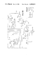
- FIG. 1 shows a block diagram of the character reading system making up the present invention
- FIG. 2 is a schematic diagram of the analog signals of FIG. 3 which have been thresholded
- FIG. 3 is a schematic diagram of the analog signals generated by the multi-channel read head forming an image of the characters read;
- FIG. 4 is a schematic diagram of the print specifications required in the printing of a number of standard E-13B characters
- FIGS. 5A-5D inclusive taken together, disclose a block diagram of the circuits for detecting the start and the end of a character
- FIGS. 7A and 7B taken together disclose the logic circuits for generating the sequencing signals used in the present invention
- FIG. 8 is a diagram of the logic circuits including the tri-state buffers found in the buffer unit of FIG. 5B;
- FIGS. 9A-9C inclusive are diagrams of the logic circuits found in the delay and buffer unit of FIG. 5B;
- FIG. 10 is a diagram showing the manner in which FIGS. 9A-9C inclusive are arranged to form the block diagram
- FIGS. 11A and 11B taken together, disclose the logic circuits found in the multiplexing unit of FIG. 5B;
- FIG. 12 is a diagram of a portion of the logic circuits found in the threshold logic unit of FIG. 5C;
- FIGS. 13A-13D inclusive are diagrams of the logic circuits found in the peak value detector of FIG. 5C;
- FIG. 14 is a diagram showing the manner in which FIGS. 13A-13D inclusive are arranged to form the block diagram
- FIGS. 15A-15C inclusive are diagrams of the logic circuits found in the threshold logic unit of FIG. 5C showing the comparators used in comparing the threshold value with the value of the data read by the multichannel read head;
- FIG. 16 is a diagram showing the manner in which FIGS. 15A-15C inclusive are arranged to form the block diagram
- FIGS. 17A-17D inclusive taken together, form a diagram of a portion of the logic circuits found in the character start unit of FIG. 5C;
- FIG. 18, on the sheet containing FIG. 17A, is a diagram showing the manner in which FIGS. 17A-17D inclusive are arranged to form the block diagram;
- FIGS. 19A and 19B taken together, form a diagram of the logic circuits of the lookup tables used in determining whether incoming data is a spot of ink or a blank;
- FIG. 20 is a diagram of the logic circuits used in the character start unit of FIG. 5D;
- FIGS. 21A and 21B taken together, disclose the pre-character start flip-flop unit and the character start flip-flop unit of FIG. 5D;
- FIGS. 22A-22D inclusive taken together, form a diagram of the logic circuits used in the character end detection logic unit of FIG. 5D;
- FIG. 23 is a diagram showing the manner in which FIGS. 22A-22D inclusive are arranged to form the block diagram
- FIGS. 24A and 24B taken together, form a diagram of further logic circuits used in the character end detection logic unit of FIG. 5D to generate signals indicating the location of the end of the character;
- FIG. 25 is a diagram of a logic circuit for generating various control signals used in the operation of the character recognition system
- FIG. 26 is a diagram of a logic circuit for generating the character start signal
- FIG. 27 is a diagram showing various waveforms used in the character recognition system of the present invention.
- FIGS. 28A-28C taken together form a diagram of the logic circuits for delaying the data and inserting start and end of character markers in the data bit stream;
- FIG. 29 is a diagram showing the manner in which FIGS. 28A-28C inclusive are arranged to form the block diagram.
- FIG. 1 there is shown a block diagram of the character recognition system which includes a multi-channel magnetic read head 20 positioned adjacent the path of movement of a document 22 having characters printed thereon in magnetic ink. While the preferred characters in the present embodiment are printed in the form of the E-13B character font which is well-known in the art and which has been adopted by the American Bankers Association for use with banking checks in this country, it is obvious that the recognition system of the present invention can be used with any character font which produces an image of the character read when scanned by the read head 20.
- the read head 20 consists of thirty magnetic pick-up channels in which every tenth channel is multiplexed to output ten channels of discrete analog signals 24 (FIG. 3) over bus 26 upon movement of the document 22 past the read head 20.
- an image of the character read is formed by the analog signals 24 in which the character is seven channels high.
- Each analog signal 24 corresponds to the time derivative of the change of flux of the magnetized ink.
- Each of the analog signals 24 outputted by the read head 20 is amplified by an amplifier 30 and transmitted over bus 32 to a plurality of A/D converters 34 which samples the analog signals at a 98 KHz. rate by clock signals received from the clock generator 36.
- the digitized signals are transmitted over bus 38 to a rectifier unit 40 which outputs both positive and negative rectified signals over bus 44 to a thresholding logic unit 46 which applies a static threshold value to the digitized signals.
- the fixed threshold value is selected to have a signal level slightly above the background noise to separate the magnetic ink information from the background noise.
- the resulting rows of thresholded data signals 42 (FIG. 2) are then transmitted over bus 48 to character start logic unit 50 which examines the data to locate the start of the character read.
- the character start logic unit 50 upon finding a character start, will generate a pre-character signal PCS over line 52 putting the thresholding logic unit 46 in a mode to examine the same data received over bus 44 using a dynamic threshold value based on the peak value of the analog signals received from the rectifier 40.
- the thresholded data signals 42 (FIG. 2) are again transmitted to the character start logic unit 50 which determines the final start of the character read from the data received, together with the end of the character.
- These signals which are represented by binary bits are transmitted over bus 56 to an image extraction logic unit 58 for use in processing the data.
- the binary data representing the thresholded data signals 42 (FIG. 2) transmitted over bus 56 are processed by the image extraction logic unit 58 which examines every seven bits of the received data 42. If it finds a zero bit surrounded by one bits, the logic unit will fill in a one bit at that location and then determine if each of the seven bits comprises an ink spot represented by a one bit or a blank spot represented by a zero bit.
- the resulting reduced 14 ⁇ 10 bit map of the scanned character is transmitted over bus 62 to an unfolding logic unit 64 which examines the 14 ⁇ 10 bit map to locate and identify the location of the top portion of the scanned character within the bit map. Details of the construction of the image extraction logic unit 58 and the unfolding logic unit 64 are disclosed in the previously-referenced Nally et al. copending application, Ser. No. 331,936.
- the processed 14 ⁇ 10 bit map outputted by the unfolding logic unit 64 is transmitted over bus 66 to a feature matching logic unit 68 which matches known character templates to the bit map appearing on bus 66.
- the logic unit 68 will generate data and control signals over line 70 for storage in a buffer memory unit 72 identifying the template having the closest match to the received character bit map.
- the data is then transmitted to a central processing unit 74 for processing of the data. Details of the construction of the feature matching logic unit 68 are disclosed in the previously-referenced Nally et al. co-pending application, Ser. No. 331,935.
- FIGS. 5A-5D inclusive there is disclosed a block diagram of the logic circuits for determining the start and the end of the character read by the read head 20 (FIG. 1).
- the read head 20 will output one of ten analog signals 24 (FIG. 3) over each of the lines 76 to a pre-amplifier and band pass filter 30 which amplifies the signal and transmits the signals to an A/D converter 34.
- the A/D converter 34 will sample the analog signals at a 98 KHz. rate and output the digitized analog signals over line 78 to a rectification logic unit 40 (FIG. 5B) for rectifying the signals which includes converting the negative signal levels to a positive signal level.
- the rectification logic unit 40 is operated to process five channels at a time. Thus, the upper five channels are processed first followed by the lower five channels.
- the binary bits of each channel outputted by the rectification logic units 40 are transmitted over lines 80 to a buffer unit 82, a seven bit delay and buffer unit 84 and a multiplexing unit 86.
- the buffer unit 82 will output the five channels of data bits over lines 88 to the threshold logic unit 60 (FIG. 5C) which applies a fixed or static threshold to the incoming data bit to eliminate as much background noise as possible and then outputs the thresholded data bits over lines 90 to a plurality of serial-in-parallel-out register units 92.
- the register units 92 will output in parallel form the data bits of each channel over lines 94 to a character start lookup table unit 96 which examines the first seven bits of data appearing in a number of adjacent channels to determine whether the incoming data constitutes the start of a character.
- the lookup table unit 96 Upon finding a character start, the lookup table unit 96 will set a pre-character start flip-flop 98 which outputs a precharacter start signal PCS over line 52 enabling a window generator unit 102 (FIG. 5C) to operate a peak value detector unit 104 which detects the maximum peak value in each window of data bits outputted by the multiplexing unit 86 (FIG. 5B).
- the peak value that is detected representing the maximum ink intensity of the character in that window is transmitted over line 106 to the threshold logic unit 60 which generates a dynamic threshold value based on the peak value.
- the new dynamic threshold value is then applied to the data bits outputted by the delay unit 84 (FIG. 5B) which delays the incoming data bits appearing on line 80 by seven bits.
- the data bits thus processed with the new threshold value are then transmitted through the serial-in-parallel-out register units 92 to the table lookup unit 96 which again determines the character start based on the data bits received.
- the pre-character signal PCS also enables a window counter 108 to count each window in the channel containing seven bits of data after the pre-character start signal has become active (FIG. 5D).
- the counter 108 will set a character start flip-flop 110 after the appearance of the second window of data, the flip-flop outputting a character start signal START appearing on line 116 which enables the character end detection logic unit 112.
- a character end signal CHEND is transmitted over line 114, which together with the character start signal appearing on line 116 are transmitted to a character delay logic unit 100 which receives the data bits over lines 94 from the registers 92 (FIG. 5C).
- the logic unit 100 will output the data together with the character start signal START and the character end signal STOP to the feature or image extraction logic unit 58 (FIG. 1) for use by the unit in reducing the data bits to a 14 ⁇ 10 bit map in the manner described previously.
- a 7442 decoder logic unit 120 which receives the output count of a counter (not shown) over lines 122 through drivers 123.
- the decoding unit 120 will output sequencing signals SS0-SS8 inclusive over lines 124a-124l inclusive (FIG. 7A) for controlling the logic units used in processing the generated data bits.
- a 74LS74 flip-flop 121 (FIG. 7B) clocked by the buffer write multiplex signal BWTR1 appearing on line 123. The signal is used to multiplex the first five channels and then the second five channels of data. Clocking of the flip-flop 121 outputs the channel select signals CISEL1 over line 125a and CISEL2 over line 125b.
- the buffer unit comprises five 74LS244 buffer logic circuits 126a-126e inclusive (FIG. 8) which buffers five channels of rectified data bits outputted by the rectifying logic units 40 (FIG. 5B) over lines 80.
- the data bits are outputted by the buffer unit 82 over lines 88 to the threshold logic unit 60 (FIG. 5C) where a fixed threshold value is initially applied to the data.
- the rectified data bits are also inputted over lines 80 to five 3351 FIFO registers 130a-130e inclusive (FIGS.
- the delayed data bits are outputted to the buffers 132a-132e inclusive (FIGS. 9A and 9C) when enabled by the pre-character start signal PCS appearing on line 52 in a manner to be described more fully hereinafter.
- the FIFO registers 130a-130e inclusive are sequentially enabled by the sequence signals SS0 and SS2 appearing on lines 124a and 124c respectively together with the clock signals CLK1 (FIG. 27a) appearing on line 137 and CLK4 (FIG. 27d) appearing on line 139, the latter signal clocking a 74LS393 counter 136 (FIG.
- the OR gate 142 also receives a signal from AND gate 144 derived from the sequencing signals SS0 and SS2.
- the output signal of AND gate 144 is transmitted through the OR gate 146 which also receives a signal from a 74LS74 flip-flop 148 which is clocked by the output count of a 74LS393 counter 150 enabled by the sequencing signals SS5 appearing on line 124f upon reaching a count of five.
- the output signals of the counter 150 are ANDed by the AND gate 152 which clocks the flip-flop 148 whose Q output signal is transmitted through the OR gates 146 and 142. These signals enable the output function of the registers 130a-130e inclusive.
- the outputted data bits of the buffers 132a-132e inclusive are transmitted over the lines 88 to the threshold logic unit 60 (FIG. 5c) where the dynamic threshold values are applied.
- the flip-flops 136 and 148 are reset by the system reset signal BRST appearing on line 155.
- the signals are outputted from a 74LS244 buffer logic unit 157 (FIG. 25) which outputs the buffer signals CLK1, CLK3 (FIGS. 27a and c), the character end signal BCHEND, the system reset signal BRST, the precharacter start signal BPCS, the buffer write signal BWRTR and the bank switch signal BANKSW. These signals are used in controlling the operation of various logic circuits as will be described more fully hereinafter.
- the reset signal BRST appearing on line 155 is gated through the AND gate 159 by the character end signal BCHEND appearing on line 360 and is outputted over line 163 for resetting the flip-flop 148 in addition to other logic circuits of the system.
- FIGS. 11A and 11B there is shown the logic circuits in the multiplexing unit 86 (FIG. 5B) comprising a plurality of 74LS244 buffers 156a-156e inclusive which receive the rectified data bits over lines 80.
- Each of the buffer units is sequentially enabled by the channel select signals CHANNEL 1-5 inclusive appearing on lines 158 for outputting over lines 160 the seven data bits comprising each window in each of the channels to the peak value detector unit 104 (FIG. 5C) to determine the peak value of each of the windows.
- the seven binary bits appearing on lines 160 are parallel loaded into a 74LS273 latch member 162 (FIG. 13A) and also into a pair of 74LS85 comparator members 164 and 166 (FIG.
- the peak value stored in latch 162 is outputted over lines 168 to a pair of 74LS85 comparators 178 and 180 (FIG. 13B) which compare the seven bits comprising the peak value level of the current window with the peak value level of the previous window which has been stored in the latch member 170 (FIG. 13c).
- the peak value is transmitted through a 74LS244 buffer member 174 and over lines 176 to the comparators 178 and 180.
- a 74LS74 flip-flop 182 which receives a high signal over its D input line 184 from the comparator member 178, is clocked by a signal over line 186 which is derived from the output signal of the window generator 102 (FIG. 5C) comprising a 74LS393 counter 188 (FIG. 13D) clocked by two of the sequenced signals SS1 appearing on line 124b.
- a 74LS393 counter 188 (FIG. 13D) clocked by two of the sequenced signals SS1 appearing on line 124b.
- an AND gate 192 Upon the counter 188 reaching a count of 7, an AND gate 192 will output a high signal over line 194 to the OR gate 196, line 198 and AND gate 200 whose output signal over line 186 will clock the flip-flop member 182.
- the AND gate 200 is enabled by the clock signal CLK3 (FIG. 27c) appearing on line 201 and the sequence control signal SS5 appearing on line 124g.
- either the peak value of the current window or the previous window is outputted over lines 176 from the latch member 204 (FIG. 13C) to a second 74LS273 latch member 206 which is clocked by the high signal appearing on line 198 and transmitted through the AND gate 208 when enabled by the sequence control signal SS6 appearing on line 124d (FIG. 13D).
- the latch member 206 will output the selected seven data bits comprising the peak value to a 2716 EPROM member 209 which will generate a fixed or static threshold value over the output lines 212.
- the EPROM member 209 when in a dynamic threshold mode, is programmed to divide the value of the inputted seven data bits representing the peak value of each window by a constant such as 6 or 8 representing an ink intensity value to produce a dynamic threshold value.
- the fixed threshold value and the dynamic threshold value are outputted over lines 212 to a 74LS244 buffer 214 (FIG. 12) which outputs the threshold values over lines 215.
- a 74LS42 decoder 216 which, in response to the output count of a 74LS39 counter 218, will output over lines 158 the channel select control signals CHANNEL 1-CHANNEL 5 inclusive which sequentially enables the buffer members 156a-156e inclusive (FIGS. 11A and 11B) to output the seven bits which comprise the current window for each of the CHANNELS 1-5 inclusive over lines 160 to the latch member 162 (FIG. 13A).
- the counter 218 is reset by the Q output signal of a 74LS74 flip-flop member 220 which is reset by a high signal appearing on the output line 222 of the decoder 216 and which is transmitted through the AND gate 224 to the clear input of the flip-flop 220.
- the latch member 162 (FIG. 13A) is reset by the Q output signal of a 74LS74 flip-flop 226 when clocked by the signal SS8 (FIG. 7A) transmitted through the AND gate 228 over line 124j.
- the threshold value for each of the windows of each channel appearing on lines 215 is transmitted to a plurality of 74LS85 comparators 230a-230j inclusive (FIGS. 15A-15C inclusive) which compare the threshold values to the signal levels in each window for all ten channels appearing on lines 158.
- the data bits outputted by the buffers 126a-126e inclusive are compared to a fixed threshold value while after the generation of the signal, the same data bits outputted from the buffers 132a-132e (FIGS. 9A and 9C) which are delayed seven bit times is compared to a dynamic threshold value based on the peak value of the data bits appearing in the first window.
- the comparators 230a-230j When the value of the data bits appearing on the input lines 88 exceeds the threshold value appearing on lines 215, the comparators 230a-230j will output a high signal on lines 232 which is inputted into the D input of the 74LS74 flip-flops 234a-234e (FIGS. 15A-15C inclusive.
- the flip-flops when clocked by the timing signal WRTR1 appearing on line 236, will output a signal over lines 90 which is inverted by the inverters 240 and then transmitted to a plurality of 74LS164 serial-in-parallel-out registers 242a-242j (FIGS.
- the EPROM members 250a-250e inclusive find that the seven bits in the first window do not contain two consecutive blank bits, a high signal will appear on lines 252 which is latched in the 74LS273 latch members 254a and 254b (FIG. 20).
- the latch member 254a will store the results for each window processed in channels 1-5 while latch 254b will store the results for channels 6-10.
- the signals stored in latch 254a are clocked out over lines 256 to a 2708L EPROM 258 by the sequence control signal SS2 (FIG. 27e) which appears on line 124c. This signal is inverted by the inverter 262 and clocked through the AND gate 264a by the clock signal CLK3 (FIG. 27c) appearing on line 201.
- the signals stored in latch 254b are clocked by the sequence control signal SS4 (FIG. 27e) appearing on line 124e and which is clocked through the AND gate 264 b.
- the signals appearing on lines 252 are also inputted into a NOR gate 270 (FIG. 19A) whose output signal is inverted by the inverter 272 and inputted into the D input of a pair of 74LS74 flip-flops 274 and 276 (FIG. 19B).
- the flip-flop 274 is clocked by the sequence control signal SS2 (FIG. 27e) appearing on line 124c to clock the signals of the upper five channels.
- the flip-flop 276 is clocked by the sequence control signal SS4 appearing on line 124e to latch the signals of the lower five channels.
- the OR gate 280 will output a high signal I/B over line 284, while if the signal represents a blank spot, the signal I/B will be low. As will be described more fully hereinafter, the signal I/B is used in determining the end of character signal.
- the EPROM 258 (FIG. 20), comprising a lookup table, will compare the windows in each of the ten channels. If the corresponding windows in two channels are indicated to comprise an ink spot, a high signal will appear on the output line 286 of the EPROM member 258 indicating the start of a character. This signal is inputted into the J input of the pre-character flip-flop 98 (FIGS. 5D and 21A) which, when clocked by the sequence control signal SS5 appearing on line 124f, will output the pre-character start signal PCS (FIG. 27e) over line 52. As described previously, the signal PCS will enable the EPROM member 209 (FIG.
- the clocking of the flip-flop 98 (FIG. 21A) by the sequence control signal SS5 appearing on line 124f results in the Q output signal clocking a second 74LS107 flip-flop 290 (FIG. 21B) whose Q output signal over line 292 enables the 74LS293 window counter 108 (FIG. 5D) thereby initiating a new counting operation.
- a high signal appearing on line 286 will go low at the start of the operation of the counter 108 as a result of the clocking of a flip-flop 294 (FIG. 21A) by the precharacter start signal PCS appearing on line 52.
- the flip-flop 294 will output the clear signals BCLRI over line 296 and BCLR2 over line 298, clearing the serial-in-parallel-out registers 242a-242f inclusive (FIGS. 17A-17D inclusive) resulting in the output signal of the EPROM 258 (FIG. 20) appearing on line 286 going low. If the counter 108 reaches a count of 7 which corresponds to the number of bits in the first window, the AND gate 300 will be enabled to output a high signal over line 302 to clock the flip-flop 110. If at this time, a high signal has appeared on line 286 indicating the presence of a character start, the flip-flop 110 will output the character start signal CS over line 116 to the character delay logic unit 100 (FIG. 5D).
- the counter 108 will continue counting up to 14 at which time, the output count signals of the counter 108 enables the AND gates 304 and 306 to preset the flip-flop 110 to output the character start signal CS over line 116 and the signal CS over line 295. It will be seen that this logic circuit will establish the character start in the second window when the character start is not found in the first window processed.
- the signal CS appearing on the Q output line 295 of flip-flop 110 (FIG. 21B) is inputted into the character end detection logic unit 112 (FIG. 5D) which includes an OR gate 308 (FIG. 22A).
- the OR gate 308 also receives the output signal of a 74LS121 multivibrator member 310, which signal (FIG. 27i) goes high when a transition occurs between an ink spot and a blank spot representing the end of a black bar portion of a character.
- the number of bits of the right hand amount character indicated generally by the numeral 309 may comprise three bars 311 whose width may vary between 13 mils and 26 mils.
- the output of the OR gate 308 (FIG. 22A) is connected to the clear input of a pair of 74LS193 counters 312 and 314 (FIG. 22B).
- the counters 312 and 314 when enabled by the appearance of the character start signal CS on line 295 will count the width of the character read represented by the clock pulses CLK3 (FIG. 27c) appearing on line 201 and transmitted through a NAND gate 316.
- the output count of the counters 312 and 314 are inputted over lines 318 to a pair of 74LS283 adders 320 and 322 (FIG. 22B) which accumulate the input count to produce on output lines 324 the total bit width of the character being scanned or the blank space between the characters.
- the output lines 324 of the adders 320 and 322 are connected to a 74LS273 latch member 326 which is clocked by the signal BLNK (FIG. 27i) outputted over line 329 of a 74LS74 flip-flop 330 (FIG. 22A).
- the flip-flop 330 receives over line 284 the signal I/B (FIG. 19B) indicating whether the binary bit being examined is an ink spot (1) or a blank spot (0).
- the flip-flop 330 is clocked by the clock signals CLK3 (FIG. 27c) appearing on line 201 and transmitted through the AND gate 332 by the sequence control signal SS4 (FIG. 27e) appearing on line 124e (FIG. 7A).
- the flip-flop 330 is also enabled by the character start signal CS appearing on line 116.
- the signal I/B goes from high to low indicating the end of a black bar of a character
- the signal BLNK appearing on the output line 328 of the flip-flop 330 will go high, clocking the latch member 326 which latches the width of the black bar appearing on the output lines 324 of the adders 320 and 322.
- the changing of the voltage level of the signal I/B also enables the flip-flop 330 to output the low signal BLNK over line 329 which enables the multi-vibrator member 310 to output a high signal through the OR gate 308 which clears the counters 312 and 314.
- the counters 312 and 314 will now start counting the width of the blank space the total of which is outputted over lines 324 by the adders 320 and 322 (FIG. 22B).
- the counter will again be cleared and start another count representing the width of the black bar.
- the width of the black bar being scanned will also be outputted over lines 334 for use in generating marker signals indicating the end of the character scanned.
- the data signals representing the total width of the black bar appearing on lines 324 is inputted into a 2708 EPROM member 336 (FIG. 22D) which, in response to the value of the input data representing the width of the character appearing on lines 324, will output over lines 338 a value representing the number of blank columns or bits which must follow the transition from ink to blank to have a valid end of character condition.
- a 2708 EPROM member 336 FIG. 22D
- the width of the first black bar 311 of the amount character 309 will be 26 mils before the occurrence of the blank space 313 comprising 13 mils wide.
- the data signals stored in the latch member 340 are outputted over lines 348 (FIG. 22D) to a pair of 74LS85 comparators 350 and 351 (FIG. 22C) which compares the blank width requirements for an end of character condition with the output of the counters 312 and 314 (FIG. 22B) which at this time are counting the blank columns being scanned. If the output count appearing on lines 318 representing the width of the blank space exceeds the value appearing on lines 348, a high signal will appear on line 352 of the comparator 350 which signal is gated by the AND gate 354.
- the AND gate 354 is enabled by the signal BLNK appearing on line 328.
- the AND gate 356 is enabled by the character start signal CS (FIG. 27g) appearing on line 116.
- the output signal of the AND gate 356 is inputted into the D input of a 74LS74 flip-flop 358.
- the flip-flop 358 is clocked by the signal CLK3 (FIG. 27c) appearing on line 201 and the sequence control signal SS6 appearing on line 124l (FIG. 7A). Clocking of the flip-flop 358 results in the outputting of the end of character signal CH END (FIG. 27k) appearing on line 114 which, after being delayed by the character delay logic circuit 100 (FIG. 5D), is transmitted to the image extraction logic unit 58 (FIG. 1).
- the inverted character end signal CH END appearing on the output line 360 of the flip-flop 358 will disable the flip-flop 110 (FIG. 21B) from outputting the character start signal CS.
- the data bits appearing on lines 334 (FIG. 22A) representing the width of the character being scanned is transmitted to a 74LS273 latch member 362 (FIG. 24B) which is clocked by the signal CH END appearing on line 116.
- the value of the character width stored in the latch member 362 is loaded into a pair of 74LS193 counter members 364 and 366 (FIG. 24B) by a signal (FIG. 27m) appearing on lines 365 and which are clocked by the clock signals CLK2 (FIG. 27b) and CLK4 (FIG. 27d) appearing on lines 368 and 139 respectively.
- CLK2 FIG. 27b
- CLK4 FIG. 27d
- the OR gate 376 through the OR gate 376 to the clock input of the counter member 364.
- the counter members 364 and 366 will count down from the value of the character width inputted into the counters from the latch member 362. Upon reaching a count of 0, the counter 366 will output a high signal over line 378 which is inverted by the inverter 380 to clock a 74LS74 flip-flop 382.
- the Q output signal of the flip-flop 382 is gated through an OR gate 384 to a 74LS193 counter 386 (FIG.
- the maximum width between the characters is 125 mils.
- a start of character marker in addition to the end of character marker is inserted in the data bits.
- the signal will clock a flip-flop (not shown) which outputs a pair of start of character marker signals STMK1 and STMK2 over lines 394 and 396 respectively into the OR gates 398a-398j inclusive (FIGS. 28A-28C inclusive) which also receive the delayed data bits SHD 1 -SHD 10 inclusive outputted by the shift registers 392a-392e over lines 400.
- the data bits representing the character scanned are outputted from the OR gates 391a-391j over lines 402 which comprise the bus 56 (FIG. 1) to the image extraction logic unit 58 in response to the clock signals SS5 appearing on lines 124g of the end of character marker signals CEMK1 and CEMK2 appearing on lines 388 and 390 and inputted into the OR gates 391a-391j inclusive, which will also result in the data being transmitted to the image extraction logic unit 58.
- FIG. 26 there is shown the logic circuit for outputting the delayed character start signal START to the image extraction unit 58.
- a 74LS74 flip-flop 406 which is clocked by the character start signal CS appearing on line 295. Clocking of the flip-flop 406 outputs a high signal over line 408 which clocks a second 74LS74 flip-flop 410 whose Q output signal appearing on line 412 enables a 74LS393 counter 414.
- a high signal will be outputted over line 416 to a NOR gate 418 which outputs the low character start signal START over line 420 to the image extraction unit 58 (FIG. 1).
- the flip-flop 406 will be clocked to output a high signal over the Q output line 422 which clocks a 74LS74 flip-flop 424.
- the clocking of the flip-flop 424 results in the operation of a second 74LS393 counter 426 (FIG. 26) which enables the NOR gate 418 to output the character start signal START over line 420 upon reaching a count of 128.
- the logic circuit elements are reset by system reset signal RST appearing on line 155 and the sequence control signal SS3 appearing on line 124d (FIG. 7A).
- the rectified data bits representing each channel of the read head 20 is inputted into the comparators 230a-230f (FIGS. 15A-15C inclusive) which applies a fixed threshold value to each seven bits of data comprising a window.
- the threshold data is then inputted into an EPROM member 258 (FIG. 20) which examines the data bits to determine if a character start requirement is met. If the corresponding windows in any of two channels are found to contain ink spots, the flip-flop 98 (FIG. 21A) will output a pre-character start signal PCS which controls the EPROM member 209 (FIG. 13C) to generate a dynamic threshold value based upon the maximum peak values found in the first window of each channel.
- the pre-character start signal PCS will enable the buffer members 132a-132e inclusive (FIGS. 9A and 9C) to output the delayed first windows of each channel to the peak value detector unit 104 (FIG. 5C) which generates values representing the peak value in each of the first windows of each channel.
- the EPROM member 209 (FIG. 13C) will divide the peak values found by a constant to output a dynamic threshold value which is then applied to the data bits found in each of the first windows by the comparators 230a-230f inclusive. The threshold values are then transmitted to the EPROM member 258 (FIG. 20) which again applies the character start requirements to the received data.
- the character start flip-flop 110 (FIG. 21B) will output the character start signal CS. If the requirements are not met during the processing of the first windows, the window counter 108 upon reaching a count of 14 representing the second window will preset the character start flip-flop 110 to output the character start signals CS and CS. Once this occurs, the accumulated width of the character is transmitted to the EPROM member 336 (FIG. 22D) which generates a value representing the blank spaces which must follow the end of the character. If the blank spaces are sensed, the flip-flop 358 (FIG. 22C) is then operated to generate the character end signal CHEND. Marker signals are then inserted in the data bits being outputted to the image extraction logic circuit 58 indicating the start and end of the character.
- the integrated circuit networks having a numerical designation disclosed herein are commercially available from the Texas Instruments Corporation of Dallas, Tex.
Abstract
Description
Claims (17)
Priority Applications (7)
| Application Number | Priority Date | Filing Date | Title |
|---|---|---|---|
| US06/331,946 US4490853A (en) | 1981-12-17 | 1981-12-17 | Matrix character reading system |
| CA000416910A CA1175147A (en) | 1981-12-17 | 1982-12-02 | Matrix character reading system |
| DE8383900323T DE3275879D1 (en) | 1981-12-17 | 1982-12-14 | Method and system for timing during character recognition |
| DE198383900323T DE98284T1 (en) | 1981-12-17 | 1982-12-14 | METHOD AND SYSTEM FOR SYNCHRONIZING DURING LICENSE PLATE RECOGNITION. |
| EP83900323A EP0098284B1 (en) | 1981-12-17 | 1982-12-14 | Method and system for timing during character recognition |
| PCT/US1982/001763 WO1983002185A1 (en) | 1981-12-17 | 1982-12-14 | Method and system for timing during character recognition |
| JP83500428A JPS58502118A (en) | 1981-12-17 | 1982-12-14 | Character reading method and system |
Applications Claiming Priority (1)
| Application Number | Priority Date | Filing Date | Title |
|---|---|---|---|
| US06/331,946 US4490853A (en) | 1981-12-17 | 1981-12-17 | Matrix character reading system |
Publications (1)
| Publication Number | Publication Date |
|---|---|
| US4490853A true US4490853A (en) | 1984-12-25 |
Family
ID=23296036
Family Applications (1)
| Application Number | Title | Priority Date | Filing Date |
|---|---|---|---|
| US06/331,946 Expired - Lifetime US4490853A (en) | 1981-12-17 | 1981-12-17 | Matrix character reading system |
Country Status (6)
| Country | Link |
|---|---|
| US (1) | US4490853A (en) |
| EP (1) | EP0098284B1 (en) |
| JP (1) | JPS58502118A (en) |
| CA (1) | CA1175147A (en) |
| DE (2) | DE3275879D1 (en) |
| WO (1) | WO1983002185A1 (en) |
Cited By (5)
| Publication number | Priority date | Publication date | Assignee | Title |
|---|---|---|---|---|
| US4724307A (en) * | 1986-04-29 | 1988-02-09 | Gtech Corporation | Marked card reader |
| US5416308A (en) * | 1991-08-29 | 1995-05-16 | Video Lottery Technologies, Inc. | Transaction document reader |
| US5982943A (en) * | 1992-09-14 | 1999-11-09 | Startek Eng. Inc. | Method for determining background or object pixel for digitizing image data |
| USRE38419E1 (en) | 1986-05-13 | 2004-02-10 | Ncr Corporation | Computer interface device |
| US7139591B2 (en) | 1993-10-13 | 2006-11-21 | Dataquill Limited | Hand held telecommunications and data entry device |
Citations (5)
| Publication number | Priority date | Publication date | Assignee | Title |
|---|---|---|---|---|
| US3526876A (en) * | 1965-10-24 | 1970-09-01 | Ibm | Character separation apparatus for character recognition machines |
| US3535682A (en) * | 1965-12-10 | 1970-10-20 | Lundy Electronics & Syst Inc | Waveform recognition system |
| US3992697A (en) * | 1974-12-27 | 1976-11-16 | Scan-Data Corporation | Character recognition system utilizing feature extraction |
| US4206442A (en) * | 1974-07-03 | 1980-06-03 | Nippon Electric Co., Ltd. | Letter segmenting apparatus for OCR comprising multi-level segmentor operable when binary segmenting fails |
| US4277776A (en) * | 1979-10-01 | 1981-07-07 | Ncr Canada Ltd - Ncr Canada Ltee | Magnetic ink character recognition apparatus |
Family Cites Families (9)
| Publication number | Priority date | Publication date | Assignee | Title |
|---|---|---|---|---|
| NL128938C (en) * | 1957-12-23 | |||
| US3382482A (en) * | 1961-10-17 | 1968-05-07 | Character Recognition Corp | Character recognition system |
| BE637372A (en) * | 1962-09-24 | |||
| US3528058A (en) * | 1966-05-27 | 1970-09-08 | Ibm | Character recognition system |
| US3987411A (en) * | 1975-08-11 | 1976-10-19 | Burroughs Corporation | Character recognition system employing extraneous and required peak detection with variable threshold controlled timing |
| US4058706A (en) * | 1976-04-23 | 1977-11-15 | Recognition Equipment Incorporated | MICR data lift system |
| DE3070672D1 (en) * | 1979-10-01 | 1985-06-27 | Ncr Canada | Character recognition apparatus and method, using waveform analysis |
| AU533978B2 (en) * | 1979-11-16 | 1983-12-22 | Tokyo Electric Co. Ltd. | Character reader |
| US4420742A (en) * | 1980-05-09 | 1983-12-13 | Hitachi, Ltd. | Scan signal processing system |
-
1981
- 1981-12-17 US US06/331,946 patent/US4490853A/en not_active Expired - Lifetime
-
1982
- 1982-12-02 CA CA000416910A patent/CA1175147A/en not_active Expired
- 1982-12-14 JP JP83500428A patent/JPS58502118A/en active Pending
- 1982-12-14 WO PCT/US1982/001763 patent/WO1983002185A1/en active IP Right Grant
- 1982-12-14 DE DE8383900323T patent/DE3275879D1/en not_active Expired
- 1982-12-14 EP EP83900323A patent/EP0098284B1/en not_active Expired
- 1982-12-14 DE DE198383900323T patent/DE98284T1/en active Pending
Patent Citations (5)
| Publication number | Priority date | Publication date | Assignee | Title |
|---|---|---|---|---|
| US3526876A (en) * | 1965-10-24 | 1970-09-01 | Ibm | Character separation apparatus for character recognition machines |
| US3535682A (en) * | 1965-12-10 | 1970-10-20 | Lundy Electronics & Syst Inc | Waveform recognition system |
| US4206442A (en) * | 1974-07-03 | 1980-06-03 | Nippon Electric Co., Ltd. | Letter segmenting apparatus for OCR comprising multi-level segmentor operable when binary segmenting fails |
| US3992697A (en) * | 1974-12-27 | 1976-11-16 | Scan-Data Corporation | Character recognition system utilizing feature extraction |
| US4277776A (en) * | 1979-10-01 | 1981-07-07 | Ncr Canada Ltd - Ncr Canada Ltee | Magnetic ink character recognition apparatus |
Cited By (8)
| Publication number | Priority date | Publication date | Assignee | Title |
|---|---|---|---|---|
| US4724307A (en) * | 1986-04-29 | 1988-02-09 | Gtech Corporation | Marked card reader |
| USRE38419E1 (en) | 1986-05-13 | 2004-02-10 | Ncr Corporation | Computer interface device |
| US5416308A (en) * | 1991-08-29 | 1995-05-16 | Video Lottery Technologies, Inc. | Transaction document reader |
| US5982943A (en) * | 1992-09-14 | 1999-11-09 | Startek Eng. Inc. | Method for determining background or object pixel for digitizing image data |
| US7139591B2 (en) | 1993-10-13 | 2006-11-21 | Dataquill Limited | Hand held telecommunications and data entry device |
| US7505785B2 (en) | 1993-10-13 | 2009-03-17 | Dataquill Limited | Data entry systems |
| US7920898B2 (en) | 1993-10-13 | 2011-04-05 | Dataquill Limited | Data entry systems |
| US8290538B2 (en) | 1993-10-13 | 2012-10-16 | Dataquill Limited | Data entry systems |
Also Published As
| Publication number | Publication date |
|---|---|
| EP0098284A1 (en) | 1984-01-18 |
| WO1983002185A1 (en) | 1983-06-23 |
| CA1175147A (en) | 1984-09-25 |
| DE3275879D1 (en) | 1987-04-30 |
| DE98284T1 (en) | 1984-05-10 |
| JPS58502118A (en) | 1983-12-08 |
| EP0098284B1 (en) | 1987-03-25 |
Similar Documents
| Publication | Publication Date | Title |
|---|---|---|
| US4143356A (en) | Character recognition apparatus | |
| EP0096066B1 (en) | Method and system for processing data signals representing an unknown character | |
| US4148010A (en) | Magnetic ink character reader system | |
| US5134663A (en) | Center line magnetic ink character recognition system | |
| EP0120080B1 (en) | Method and system for identifying documents | |
| CA1119725A (en) | Magnetic ink character recognition waveform analyzer | |
| US4277775A (en) | Character recognition system | |
| US3634823A (en) | An optical character recognition arrangement | |
| US4490853A (en) | Matrix character reading system | |
| US5026974A (en) | Method for recognizing the leading edge of a character in E13B font | |
| US3177469A (en) | Character recognition | |
| US4490850A (en) | Matrix character recognition | |
| US4845348A (en) | Method and apparatus for reading bar code magnetic ink characters | |
| US3879707A (en) | Character recognition system for bar coded characters | |
| US4277776A (en) | Magnetic ink character recognition apparatus | |
| JPH07182448A (en) | Character recognition method | |
| Shinjo et al. | A recursive analysis for form cell recognition | |
| EP0451252B1 (en) | Ratio detection character recognition apparatus | |
| US3851309A (en) | Character recognition apparatus | |
| Chandran et al. | Structure recognition and information extraction from tabular documents | |
| US6464147B1 (en) | Dual gap read head for magnetic ink character recognition | |
| JPH1125214A (en) | Device for identifying picture | |
| JP3160458B2 (en) | Character reading device and character reading method | |
| US3320588A (en) | Character reader | |
| JPH07160810A (en) | Character recognizing device |
Legal Events
| Date | Code | Title | Description |
|---|---|---|---|
| AS | Assignment |
Owner name: NCR CANADA LTD - NCR CANADA LTEE, MISSISSAUGA, ONT Free format text: ASSIGNMENT OF ASSIGNORS INTEREST.;ASSIGNORS:NALLY, ROBERT B.;VANCE, ERIC J.;LEUNG, PATRICK C.;AND OTHERS;REEL/FRAME:003969/0352 Effective date: 19811209 |
|
| AS | Assignment |
Owner name: NCR CORPORATION, 1700 S. PATTERSON BLVD. DAYTON, O Free format text: ASSIGNMENT OF ASSIGNORS INTEREST.;ASSIGNOR:NCR CANADA LTD- NCR CANADA LTEE, A CORP. OF CANADA;REEL/FRAME:004044/0881 Effective date: 19820924 Owner name: NCR CORPORATION, A CORP. OF MD, OHIO Free format text: ASSIGNMENT OF ASSIGNORS INTEREST;ASSIGNOR:NCR CANADA LTD- NCR CANADA LTEE, A CORP. OF CANADA;REEL/FRAME:004044/0881 Effective date: 19820924 |
|
| STCF | Information on status: patent grant |
Free format text: PATENTED CASE |
|
| AS | Assignment |
Owner name: NCR CANADA LTD - NCR CANADA LTEE MISSISSAUGA, ONT Free format text: ASSIGNMENT OF ASSIGNORS INTEREST.;ASSIGNOR:NCR CORPORATION;REEL/FRAME:004425/0385 Effective date: 19850626 |
|
| FPAY | Fee payment |
Year of fee payment: 4 |
|
| FPAY | Fee payment |
Year of fee payment: 8 |
|
| FPAY | Fee payment |
Year of fee payment: 12 |