US4499111A - Process for continuously determining the moisture content of spoilable grain products - Google Patents
Process for continuously determining the moisture content of spoilable grain products Download PDFInfo
- Publication number
- US4499111A US4499111A US06/392,137 US39213782A US4499111A US 4499111 A US4499111 A US 4499111A US 39213782 A US39213782 A US 39213782A US 4499111 A US4499111 A US 4499111A
- Authority
- US
- United States
- Prior art keywords
- product
- measuring
- measuring section
- accordance
- product stream
- Prior art date
- Legal status (The legal status is an assumption and is not a legal conclusion. Google has not performed a legal analysis and makes no representation as to the accuracy of the status listed.)
- Expired - Lifetime
Links
Images


Classifications
-
- G—PHYSICS
- G01—MEASURING; TESTING
- G01N—INVESTIGATING OR ANALYSING MATERIALS BY DETERMINING THEIR CHEMICAL OR PHYSICAL PROPERTIES
- G01N33/00—Investigating or analysing materials by specific methods not covered by groups G01N1/00 - G01N31/00
- G01N33/02—Food
- G01N33/10—Starch-containing substances, e.g. dough
-
- G—PHYSICS
- G01—MEASURING; TESTING
- G01N—INVESTIGATING OR ANALYSING MATERIALS BY DETERMINING THEIR CHEMICAL OR PHYSICAL PROPERTIES
- G01N27/00—Investigating or analysing materials by the use of electric, electrochemical, or magnetic means
- G01N27/02—Investigating or analysing materials by the use of electric, electrochemical, or magnetic means by investigating impedance
- G01N27/22—Investigating or analysing materials by the use of electric, electrochemical, or magnetic means by investigating impedance by investigating capacitance
- G01N27/223—Investigating or analysing materials by the use of electric, electrochemical, or magnetic means by investigating impedance by investigating capacitance for determining moisture content, e.g. humidity
Definitions
- the invention concerns a process for continuously determining the moisture content of a spoilable foodstuff, in particular, of grain and processed products of the latter (referred to as "product"), which is moved along a production line as a product stream and passed, at least in part, through a measuring section.
- the invention also concerns a device, especially for carrying out the invention process, for continuously determining the moisture content of spoilable foodstuffs, in particular, grain and processed products of the latter, as it is moved through a measuring housing.
- the good itself is to be found in two extreme conditions, namely on the one hand at rest, stored in silos, and on the other hand in flow from processing stage to processing stage. It is particularly difficult to obtain exact material values in a continually moving product, and therefore in practice, the laboratory method performed on samples has been used for determination of the exact value.
- Manipulation of the sample taking mechanism is awkward, particularly for large silo cells, since to the extent possible, samples must be drawn from various places within the silo, while within silos very high pressures and compressions are usual.
- a further difficulty lies in the fact that the product moisture can vary between relatively wide extreme values, which has a direct influence on the product dry volume, and also, for example, the density and electrical conductivity.
- the grain is removed by a mechanism from a product stream in a batch or quasi-continuous operation, and poured in a certain weighed quantity into a measurement container.
- the measurement container is in part constituted as a condenser, and a measurement is made by determination of an electrical value in the form of the capacitance of the condenser constituted by the container with the product, and in evaluation is converted to the quantity of water present in the sample.
- This instrument reflects the actual water content of the measurement sample, but it is questionable with this method, whether the measurement values are representative of the entire product stream.
- the product throughput must be received in a subsequent continuously operating weighing system, and the necessary supplemental water quantity computed and added. Although this system is employed relatively frequently in practice, it may often be insufficient for the requirements in a mill. If the moistures or water contents produced are namely determined by an exact laboratory method, for example, in a drying oven, variations in the relative moisture content of frequently up to half a percent, and sometimes up to one percent are discovered.
- the electrical measurement method here described has the particular failing that the values determined are very much type dependent. To exclude this factor, calibration must be performed for each grain type before beginning measurement. For transparent reasons, this calibration is useless in the case of a mixing of more than one type, if the mixing ratio itself is not precisely known or precisely defined.
- measuring processes have not found any substantive application in the milling filed. Measuring processes with microwaves, gamma-rays and the like are not being considered due to the risks inherent in the rays. Other measuring processes on the other hand are suitable for dead materials, textiles, paper, sand and the like and are precluded from grain which is a living substance, since the measuring results are totally unusable.
- a part of the invention is to overcome the known deficiency in the state of the art, in particular to find a new process for determination of physical quantities, in which the values determined for as large as possible a quantity of product and to as high as possible a precision are made available.
- the process should render unnecessary any constant recalibration both with respect to special grain types, and with respect to short and long term behavior.
- the solution is to be simple and economical to manufacture, and be operable even by personnel with little training.
- the solution provided by the invention is distinguished by the fact that a pourable average of the product stream is created continuously within the measuring section, and the product moisture content of this product average is measured electrically on a continuous basis.
- the solution provided by the invention is distinguished by the fact that the measuring housing has a capacitor as a continuous-flow measuring section and a device for continuously controlling the creation of a pourable product average.
- the new invention establishes a new branch for automation of mill operation.
- the new process permits the moisture content of the product to be determined with considerably higher accuracy, and on the other, it makes possible the elimination of moisture as a source of problems, for example, in the exact measurement of flow rates or levels.
- the invention suggests first of all that a product average be produced in place of the awkward process employed to date of taking samples and evaluating them individually. In this process the product average should be constantly reformed in a continuous, trickling flow with simultaneous electrical measurement of the product.
- the quantity of product measured may actually lie within range from a few percent of the entire quantity of product up to 100 percent, according to the particular situation.
- the fact has been disregarded that the shape and the composition of the measurement sample are just as important as the measuring process itself. With poor sampling, even the best measuring method is rendered unusable.
- Practice has shown that measurement values obtained according to the principles of the invention even lie within the mean error of the best laboratory methods; moisture content is therefore obviously determined more effectively than in all methods previously used.
- the invention also makes possible a large number of particularly advantageous design elaborations.
- a relatively large quantity of product for example, five to ten liters, may be determined with a single measuring process.
- an average of the product stream is produced in the measuring section with respect to time, such that a constant percentage of the product stream is scanned for the determination of moisture content. To extend this concept, this percentage may also be present. In this manner, as mentioned in the beginning, it is possible with unknown mistures to measure a substantially larger proportion of the product, and therefore for the measuring reliability to be increased.
- the movement of the product be retarded in the measuring section in a manner that is free of pressure, that is, occurring by means of gravity alone; that it trickle, as it were, through the measuring section as in an egg timer or hourglass; and that the moisture content be measured during this process.
- a first partial flow of product prefferably passed through the measuring section and a second partial flow through a bypass, each by gravitational force, and to be retarded simultaneously in their downward movement in the section of a measuring housing formed by the measuring section and the bypass, in particular, to be delayed to different degrees in the measuring section and the bypass.
- the two partial flows prefferably be created on the overflow principle and to be reunited beneath the measuring section in such a manner that a controlled backlog in the measuring section is created in the area where the two partial flows are brought together.
- the outlet port from the measuring section can be designed as a presetable gate valve in order to bring about the passage of a certain desired percentage of the product through the measuring section.
- the movement of the product in the bypass is controlled according to another idea, for the purpose of maintaining a constant level in the bypass to ensure a constant product backlog in the measuring section.
- the capacitance in the measuring section designed as a measuring capacitor is preferably measured directly, and the values obtained delivered to an electronic evaluator for the determination of the moisture content of the product. It is preferable for the measurement capacitor to be charged to a certain voltage in a first phase, and in a second phase for a reference capacitor to be connected to the measuring capacitor, the measuring capacitor to be discharged into the reference capacitor, and the voltage obtained in this manner to be measured over the reference capacitor and delivered to the electronic evaluator, the two phases being repeated in a cyclical manner, the reference capacitor being discharged during the first phase and the voltage across the reference capacitor being delivered to a reservoir at the end of the second phase. In the reservoir a mean value may also be formed from several measured values for determining the moisture content of the product. Another possible elaboration is for the product to be weighted in the measuring section and and the instantaneous weight value to be determined during the electrical measurement, the product stream in the measuring section being controlled in such a manner that the measuring section remains essentially full at all times.
- the amount of water lacking--relative to a desired moisture content value-- may be determined to the same degree of accuracy in a computer, and a subsequent device for moistening the product may be immediately adjusted.
- the product supply ducts in the measurement housing run essentially in a vertical direction.
- the device used to continously control the product average prefferably has a level-regulating mechanism.
- a bypass is assigned to the measuring section to divert a portion of the product stream, as well as a regulating mechanism for the purpose of adjusting the product in the bypass to a constant level and the product in the measuring section to bring about continuous averaging.
- Simple construction is achieved by placing the measuring section and the bypass immediately adjacent to each other and connecting them by means of an overflow duct and a common product outlet, and also by the fact that the product inlet of the measuring chamber discharges essentially directly above the measuring section, and the product may be guided, flowing freely, through the overflow duct into the bypass.
- the invention device To retard the product it is also advisable for the invention device to have a throughput-regulating mechanism at the product outlet that is controlled by a level sensor located in the regulating duct, or bypass.
- the level sensor is preferably executed as a membrane located on the side of the regulating duct, which is preferably connected by pneumatic actuating elements to the overflow-regulating mechanism.
- Manual actuators are also provided for opening and closing the throughput-regulating mechanism, so that the entire device may be emptied when required.
- the invention device is provided with a throughput measuring mechanism, which determines its instantaneous throughput for the purpose of computing the amount of water to be added.
- the invention device it is also possible to install the invention device directly beneath a storage container, such that the delivery output of the storage container may be regulated by the invention device itself.
- the device it is preferable for the device to have a throughput regulating loop, with a flow rate regulating mechanism and a throughput measuring instrument, in which the electronic evaluator serves as a comparator for comparing the actual value, supplied by the throughput measuring instrument, to the desired value, supplied by a corresponding desired value control unit, and adjusts the flow rate regulating mechanism to maintain the desired value.
- the two last-named applications make possible ideal conditions for continuously measuring the flow rate of the product. In both cases the continuous flow rate measuring device receives a constant stream of product without spurious air disruptions, as a result of the enclosed product column created by the backlog.
- a subsequent device for wetting or drying the grain can be controlled reliably and very accurately by an electronic evaluator and a second computer, which has not been possible previously in practice.
- Another possible elaboration is to design the capacitor arrangement as a balance receptacle, or to support it on pressure pickups, so that the balance signal can be processed to determine the settled apparent density of the product within the measuring section.
- measuring section is designed within a measuring chamber in the measurement housing.
- a vertical section of the outer wall of the measuring chamber is designed as a first capacitor plate, and a second capacitor plate is located inside the measuring chamber.
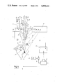
- FIG. 1 shows a measurement of moisture content and control of flow rate through a measuring section; directly under a silo;
- FIG. 2 is a diagrammatic representation of electrical measuring process
- FIG. 3 shows positioning of individual switches in temporal course according to FIG. 2;
- FIG. 4 is a principle diagram for control and regulation of a grain wetting device
- FIG. 5 shows an application of solution shown in FIG. 4 in a mill or a cleaning room
- FIG. 6 shows a measurement of moisture content and throughput directly in product
- FIG. 7 is a schematic representation of averaging in measuring chamber.
- FIG. 1 shows a principle representation of a device 56 positioned beneath a compartment 70 of a silo for continuously determining the moisture content of grain, in which the movement of the grain occurs essentially as a result of gravitational force and the shape of device 56 alone.
- Device 56 exhibits a measuring housing 16 adjacent to the outlet of silo compartment 70 that tapers at its downstream end to a product outlet 23. Following product outlet 23 downstream is a throughput control loop 71.
- the measurement housing 17 is designed and constructed in such a way that the longitudinal axes of the regulating duct 22 and the measuring chamber 1 run essentially vertically, or in the direction of the earth's gravitational field, and the bulk material trickles through them, as it were, in a manner similar to that of sand in an hourglass.
- the measuring chamber 1 has a bulk material measuring duct, or measuring section 1', that is designed as a capacitor for capacitively measuring the moisture content of the grain. As illustrated on an enlarged scale in FIG. 6, an inner wall of the measuring chamber 1 is designed as a first capacitor plate 4, and a second capacitor plate 5 is positioned inside the chamber. Under the measuring chamber 1 is a bulk material temperature sensor 6. Beneath the product outlet 23 is a throughput measuring device 7. The measured values are converted partly in a converter 8 and an electronic evaluator 9 into the desired parameter. The initial values of bulk material temperature sensor 6, throughput measuring device 7, and converter 8 are delivered by signal conductor 6', 7', or 8' to the electronic evaluator 9.
- the solution illustrated in FIG. 1 is in principle the basis for measuring the moisture content of grain and may be employed-supplemented with the above-mentioned throughput, measuring device 7 and a (second) computer 10 (see FIG. 6 )--directly for controlling wetting, that is, for influencing the moisture content of the grain in the direction of a certain value.
- FIG. 2 is a conceptual representation of the new measurement process.
- a measurement container 84 configured as a condenser, analogous to the measurement container 1 of FIG. 1, the capacitance is measured.
- FIGS. 3 and 4 For the description of the performance of the measurement, reference will be made at the same time to FIGS. 3 and 4 as well.
- FIG. 3 shows the individual switch positions of the switches I-IV in FIG. 2 during the measurement, and the trace of the voltage U 1 .
- the measurement condenser C x is charged to a particular voltage U ref .
- the reference condenser C ref is discharged.
- Switches I and III are closed.
- Switches II and IV are opened (position as in FIG. 2).
- the voltage U 1 is still zero in the initial phase.
- the charge of the measurement condenser C x is transferred to the reference condenser C ref .
- the switch II is closed for this purpose, and the switches I, III and IV are opened.
- the voltage U 1 rises until the measurement condenser is fully discharged. This charge transfer is effected by means of the operational amplifier 83.
- the voltage of U+ is transferred to an analog memory 87.
- the switch IV is closed, and the switches I-III opened.
- This phased charging and discharging of the measurement and reference condensers C x and C ref is controlled by preference by the cycle of the power supply frequency.
- FIG. 4 is represented an application of the invention for measurement and control of the water content of a pourable goods.
- the apparatus displays a measurement container 1 with a throughput regulating mechanism 17, and a regulation and control loop 18, which includes an evaluation circuit 9 and a wetting apparatus 19.
- the measurement section 16 has an inlet 20, opening essentially vertically above the measurement container 1. Parallel to the measurement container 1 runs a regulating channel 22. The regulating channel 22 and the measurement contain 1 flow together in the region above the product outlet 23. The product outlet 23 is controlled by means of a throughput regulating mechanism 17, in which a level detector 24 is included in the form of a membrane 25 in the side of the regulating channel 22.
- a strut 26 is pivoted on a joint 34, and a pneumatic regulator valve 32 is connected with the strut 26.
- the pneumatic regulator valve 32 is actuated, producing an air pressure in a duct 29.
- This air pressure operates a pressure cylinder 30, which in turn controls the gate 31 at the product outlet 23.
- the same pressure present in the duct 29 also enters a pressure chamber 28 and acts on a membrane 27.
- the pressure serves as a compensating pressure against the product pressure.
- regulating channel 22 In the regulating channel 22 are also manual actuating means for the opening and closing of the throughput regulating mechanism 17.
- a screw 33 and the strut 26 permit actuation of the pneumatic regulator valve 32, and thus completely open or close the gate 31.
- a moisture deficiency value can be determined.
- the moisture deficiency value is passed as a control quantity to a regulator 40, which controls a motor 41 which conveys the computed quantity of water lacking into the product stream.
- the water quantity delivered is echoed by a check post 43.
- FIG. 5 shows the basic plan of an installation with the new measurement apparatus.
- the raw product is drawn from storage bins 50 through special outlets 51, which hinder separation, an approximate outlet rate is established by means of a gate 52, and is fed through a bucket wheel sluice 53 and a pneumatic barrow train 54 supplied with air from the blower 55, into the moisture measurement apparatus 56.
- the details of construction of the measurement container 1 are represented in FIG. 4.
- the wetting apparatus 19' in the preferred solution has a closed housing with a rapidly turning intensive wetting rotor.
- the water content of the grain is determined in the measurement container 1, and regulated in an open or direct control loop by means of the evaluation circuit 9 and the wetting apparatus 19'.
- the wetted grain is conveyed into standing bins 60.
- the grain can be removed from the standing bins 60 after an appropriate number of hours, to be conveyed through another pneumatic transport 61 into an intensive setting apparatus 19", where a small additional quantity of water is added.
- an intensive setting apparatus 19 where a small additional quantity of water is added.
- a few tenths of a percent of water is applied as a water film on the grain, and after a working period in standing bins 63, the grain is transferred directly to the rolling carriages 64.
- FIG. 6 shows a particularly advantageous example of realization built on the basic elements of FIGS. 1, 2 and 3. The corresponding parts are therefore labelled with the same reference numbers.
- the control mechanism 91 includes a level sensor 92 and an adjusting gate 93.
- the signals from the level sensor 92 are processed by a control unit 94.
- control mechanism 91 The purpose of the control mechanism 91 is for the product to be passed with retardation through the measurement section 1' or the measurement container 1.
- the solution in FIG. 6 can be employed in such a way that the entire goods stream is passed through the measurement section 1'.
- the total throughput quantity through the measurement section need not be changed in this application.
- the control mechanism 91 serves merely to impede the product movement to a greater or lesser extent, so that the measurement container 1 is constantly filled with the goods. To ensure filling, by means of the control mechanism 91, through regulation of the opening of the adjusting gate 93, the level of the goods is maintained within a constant range 95.
- FIG. 6 shows the further possibility of the determination of the weight of the goods by a weighing mechanism, consisting of a pressure sensor or scale 2 and a corresponding support pivot 3.
- the measurement container 1 is simultaneously configured as a weighing container.
- the weighing container can be used both as a continuous throughput scale, or as a batch scale, depending on the position of the adjusting gate 93.
- FIG. 7 shows in somewhat enlarged scale the continuous averaging of the product in the measuring section 1' within measuring chamber 1 shown in FIG. 1 and FIG. 4.
- This continuous averaging that is, continuous formation of a constantly representative cross section of the bulk material flowing through intake 20, undergoes constant self-adjustment in the invention device 56.
- composition of the product that is, the individual components of the product, vary over time.
- a charge-type or batch-type variation is represented.
- the influence of the averaging may be achieved in exactly the same manner if this variation is gradual.
- the product is fed in at the intake 20 and moves downward by means of gravity alone in regulating duct 22 and measuring chamber 1 or measuring section 1', respectively.
- movement of the product is retarded by the gate valve 31, so that the various product components c, d, and e to h come to lie upon one another in layers.
- Product component a is still located within the intake 20, and product component b is about to be divided into the two paths (regulating duct 22 and measuring section 1').
- Product component i is leaving regulating duct 22 in the vicinity of gate valve 31. Even though the product is piled up to the height of the membrane 25, a high rate of flow results in regulating duct 22, corresponding to its throughput capacity and the cross section of the regulating duct.
- Circumstances are different in measuring section 1'.
- the downward movement of the product brought about by the force of gravity is retarded to a much greater extent by the shape of the measuring chamber 1, in particular, by the cross-sectional proportions in the electrical measurement area, that is, in the area of measuring section 1', and in the area of the constricted outlet aperture of measuring chamber 1. Consequently, product components e, f, g, h, i, and k are still located in measuring section 1', but no longer, in contrast, in regulating duct 22 laterally adjacent to measuring section 1'.
- the actual product content in measuring section 1' can have an order of magnitude from five liters up to twenty liters and more.
- Electrical measurement in accordance with FIG. 7 therefore encompasses a product section (average) of product components e to k.
- the effective measurement in this way lags somewhat behind the product stream, which offers another advantage, however, especially with the product section, since the addition of water than may be necessary--until it is effective in subsequent equipment--requires a certain amount of time.
- the aperture "S" and the overall throughput capacity of product through the gate valve 31 can be determined relative to each other such that either the greatest possible precision in the addition of water or optimal wetting of the product is achieved, and in this manner advantage may be taken of all the benefits of forward regulation (control) of the addition of moisture, which is preferably applied here.
- the result of the foregoing descriptions is that the invention actually produces a substantial improvement in the measuring of moisture content and control of the required addition of water.
- the electrical measuring process in particular, the capacitive measuring process, has the advantage that the entire content of the measuring section, for example, five to twenty liters, is measured continuously.
- the five to twenty liters cited represents an average of 50, 100 or more liters of grain flowing through the measuring mechanism, due to the retardation of product described in measuring section 1'. This means that the moisture content measurement constantly misses grain on the order of magnitude of a sack and therefore offers representative results.
Abstract
Description
Claims (15)
Priority Applications (1)
| Application Number | Priority Date | Filing Date | Title |
|---|---|---|---|
| US06/392,137 US4499111A (en) | 1982-02-17 | 1982-06-25 | Process for continuously determining the moisture content of spoilable grain products |
Applications Claiming Priority (2)
| Application Number | Priority Date | Filing Date | Title |
|---|---|---|---|
| US06/355,596 US4547725A (en) | 1980-06-30 | 1980-12-05 | Method and apparatus for the continuous determination of moisture pourable food |
| US06/392,137 US4499111A (en) | 1982-02-17 | 1982-06-25 | Process for continuously determining the moisture content of spoilable grain products |
Related Parent Applications (1)
| Application Number | Title | Priority Date | Filing Date |
|---|---|---|---|
| US06/355,596 Continuation-In-Part US4547725A (en) | 1980-06-30 | 1980-12-05 | Method and apparatus for the continuous determination of moisture pourable food |
Related Child Applications (1)
| Application Number | Title | Priority Date | Filing Date |
|---|---|---|---|
| US06/557,612 Division US4590795A (en) | 1980-06-30 | 1983-12-02 | Process and device for continuously determining the moisture content of spoilable foodstuffs |
Publications (1)
| Publication Number | Publication Date |
|---|---|
| US4499111A true US4499111A (en) | 1985-02-12 |
Family
ID=26998916
Family Applications (1)
| Application Number | Title | Priority Date | Filing Date |
|---|---|---|---|
| US06/392,137 Expired - Lifetime US4499111A (en) | 1982-02-17 | 1982-06-25 | Process for continuously determining the moisture content of spoilable grain products |
Country Status (1)
| Country | Link |
|---|---|
| US (1) | US4499111A (en) |
Cited By (18)
| Publication number | Priority date | Publication date | Assignee | Title |
|---|---|---|---|---|
| US4698190A (en) * | 1985-09-02 | 1987-10-06 | Kabushiki Kaisha Okawaraseisakusho | Method and apparatus of controlling granulation of moisture-absorbing powder material |
| US4812741A (en) * | 1987-02-10 | 1989-03-14 | Stowell Dennis E | Baler-mounted continuous moisture monitoring system |
| US4896795A (en) * | 1988-01-15 | 1990-01-30 | Ediger Randall J | Grain moisture sensor |
| US4929885A (en) * | 1988-11-08 | 1990-05-29 | Troxler Electronic Laboratories, Inc. | Apparatus for measuring ground moisture content of soil |
| FR2643985A1 (en) * | 1989-03-03 | 1990-09-07 | Serdia | APPARATUS FOR CONTINUOUSLY MEASURING THE SUBSTANCES OF A GRANULAR, PULVERULENT OR VISCOUS PRODUCT |
| US4994286A (en) * | 1988-05-09 | 1991-02-19 | Agrichem, Inc. | Grain conditioning method |
| US4993316A (en) * | 1988-05-09 | 1991-02-19 | Agrichem, Inc. | Seed grain conditioning apparatus |
| US5092819A (en) * | 1990-05-17 | 1992-03-03 | Schroeder Michael J | Method and apparatus for qualitatively measuring characteristics of grain to be harvested |
| US5133982A (en) * | 1991-09-25 | 1992-07-28 | Panhandle Fluid Process, Inc. | Method and apparatus for conditioning a grain flow |
| US5194275A (en) * | 1992-08-13 | 1993-03-16 | Agrichem, Inc. | Grain processing apparatus |
| US5253512A (en) * | 1991-06-13 | 1993-10-19 | Star Partners | Moisture meter for granular or powdered products, and method for measuring the degree of moisture |
| US5347468A (en) * | 1992-10-02 | 1994-09-13 | Sartec Corporation | Computerized grain delivery system |
| US5351558A (en) * | 1991-02-25 | 1994-10-04 | Claas Ohg | Device for measuring bulk flow |
| EP0851223A1 (en) * | 1996-12-27 | 1998-07-01 | Ebbe Busch Larsen | Sensor for the measurement of moisture in a flow of material |
| EP0938838A1 (en) * | 1998-02-25 | 1999-09-01 | New Holland Belgium N.V. | Sensor apparatus with butterfly valve for maintaining packing density of moving material |
| US6388453B1 (en) | 1999-01-25 | 2002-05-14 | Bryan D. Greer | Swept-frequency dielectric moisture and density sensor |
| US6440475B1 (en) | 1999-09-14 | 2002-08-27 | Sartec Corporation | Grain moisture measuring apparatus and method |
| CN112345559A (en) * | 2019-08-06 | 2021-02-09 | 中国农业机械化科学研究院 | Online grain moisture detection device and detection method of combine harvester |
Citations (6)
| Publication number | Priority date | Publication date | Assignee | Title |
|---|---|---|---|---|
| US3370360A (en) * | 1966-11-18 | 1968-02-27 | Thomas R. Smith | Apparatus for analyzing moisture content |
| US3566260A (en) * | 1968-09-30 | 1971-02-23 | Cargill Inc | Method and apparatus for measuring the moisture content of a particulate material including material flow control |
| US3886447A (en) * | 1972-05-17 | 1975-05-27 | Iwatsu Electric Co Ltd | Capacitance-voltage converter |
| SU621998A1 (en) * | 1977-03-04 | 1978-08-30 | Специальное Конструкторское Бюро По Проектированию Приборов И Средств Автоматизации | Capacitive humidity sensor |
| US4168466A (en) * | 1977-10-21 | 1979-09-18 | Agridustrial Electronics, Inc. | Moisture tester |
| US4266188A (en) * | 1979-11-30 | 1981-05-05 | Mobil Oil Corporation | Method and apparatus for measuring a component in a flow stream |
-
1982
- 1982-06-25 US US06/392,137 patent/US4499111A/en not_active Expired - Lifetime
Patent Citations (6)
| Publication number | Priority date | Publication date | Assignee | Title |
|---|---|---|---|---|
| US3370360A (en) * | 1966-11-18 | 1968-02-27 | Thomas R. Smith | Apparatus for analyzing moisture content |
| US3566260A (en) * | 1968-09-30 | 1971-02-23 | Cargill Inc | Method and apparatus for measuring the moisture content of a particulate material including material flow control |
| US3886447A (en) * | 1972-05-17 | 1975-05-27 | Iwatsu Electric Co Ltd | Capacitance-voltage converter |
| SU621998A1 (en) * | 1977-03-04 | 1978-08-30 | Специальное Конструкторское Бюро По Проектированию Приборов И Средств Автоматизации | Capacitive humidity sensor |
| US4168466A (en) * | 1977-10-21 | 1979-09-18 | Agridustrial Electronics, Inc. | Moisture tester |
| US4266188A (en) * | 1979-11-30 | 1981-05-05 | Mobil Oil Corporation | Method and apparatus for measuring a component in a flow stream |
Cited By (20)
| Publication number | Priority date | Publication date | Assignee | Title |
|---|---|---|---|---|
| US4698190A (en) * | 1985-09-02 | 1987-10-06 | Kabushiki Kaisha Okawaraseisakusho | Method and apparatus of controlling granulation of moisture-absorbing powder material |
| US4812741A (en) * | 1987-02-10 | 1989-03-14 | Stowell Dennis E | Baler-mounted continuous moisture monitoring system |
| US4896795A (en) * | 1988-01-15 | 1990-01-30 | Ediger Randall J | Grain moisture sensor |
| US4994286A (en) * | 1988-05-09 | 1991-02-19 | Agrichem, Inc. | Grain conditioning method |
| US4993316A (en) * | 1988-05-09 | 1991-02-19 | Agrichem, Inc. | Seed grain conditioning apparatus |
| US4929885A (en) * | 1988-11-08 | 1990-05-29 | Troxler Electronic Laboratories, Inc. | Apparatus for measuring ground moisture content of soil |
| AU610812B2 (en) * | 1988-11-08 | 1991-05-23 | Troxler Electronic Laboratories, Inc. | Apparatus for measuring ground moisture content of soil |
| FR2643985A1 (en) * | 1989-03-03 | 1990-09-07 | Serdia | APPARATUS FOR CONTINUOUSLY MEASURING THE SUBSTANCES OF A GRANULAR, PULVERULENT OR VISCOUS PRODUCT |
| EP0389320A1 (en) * | 1989-03-03 | 1990-09-26 | Dolige Developpement Industriel D.D.I., Societe Anonyme | Apparatus for measuring continuously the substance contents of a granular, powdery or viscous product |
| US5092819A (en) * | 1990-05-17 | 1992-03-03 | Schroeder Michael J | Method and apparatus for qualitatively measuring characteristics of grain to be harvested |
| US5351558A (en) * | 1991-02-25 | 1994-10-04 | Claas Ohg | Device for measuring bulk flow |
| US5253512A (en) * | 1991-06-13 | 1993-10-19 | Star Partners | Moisture meter for granular or powdered products, and method for measuring the degree of moisture |
| US5133982A (en) * | 1991-09-25 | 1992-07-28 | Panhandle Fluid Process, Inc. | Method and apparatus for conditioning a grain flow |
| US5194275A (en) * | 1992-08-13 | 1993-03-16 | Agrichem, Inc. | Grain processing apparatus |
| US5347468A (en) * | 1992-10-02 | 1994-09-13 | Sartec Corporation | Computerized grain delivery system |
| EP0851223A1 (en) * | 1996-12-27 | 1998-07-01 | Ebbe Busch Larsen | Sensor for the measurement of moisture in a flow of material |
| EP0938838A1 (en) * | 1998-02-25 | 1999-09-01 | New Holland Belgium N.V. | Sensor apparatus with butterfly valve for maintaining packing density of moving material |
| US6388453B1 (en) | 1999-01-25 | 2002-05-14 | Bryan D. Greer | Swept-frequency dielectric moisture and density sensor |
| US6440475B1 (en) | 1999-09-14 | 2002-08-27 | Sartec Corporation | Grain moisture measuring apparatus and method |
| CN112345559A (en) * | 2019-08-06 | 2021-02-09 | 中国农业机械化科学研究院 | Online grain moisture detection device and detection method of combine harvester |
Similar Documents
| Publication | Publication Date | Title |
|---|---|---|
| US4499111A (en) | Process for continuously determining the moisture content of spoilable grain products | |
| US4590795A (en) | Process and device for continuously determining the moisture content of spoilable foodstuffs | |
| US4547725A (en) | Method and apparatus for the continuous determination of moisture pourable food | |
| KR910005301B1 (en) | Apparatus for automatic registration of a continuous bulck material flow by means of a run-through weighting device | |
| EP0034459B1 (en) | Cereal grain moisture content measuring apparatus | |
| US5148943A (en) | Method and apparatus for metering and blending different material ingredients | |
| US4742228A (en) | Infrared measuring apparatus and process for the continuous quantitative determination of individual components of flour or other groundable food products | |
| JPH06307916A (en) | Method and equipment for determining quantity of pulverulent substance | |
| EP0824963B1 (en) | Method and apparatus for controlling water addition to grains | |
| US6672342B2 (en) | Apparatus for controlling the discharge of flowable material | |
| CN107572016B (en) | Vertical multiple groups part material blanking device and its controller | |
| MXPA97006051A (en) | Method and device for controlling the addition of water to gra | |
| US3566260A (en) | Method and apparatus for measuring the moisture content of a particulate material including material flow control | |
| CZ290176B6 (en) | Method for continuously regulating water content in bulk material and apparatus for making the same | |
| DE3760316D1 (en) | Balance for measuring the mass flow at the entrance of an extrusion device | |
| JPS6148845B2 (en) | ||
| JPS5841256B2 (en) | Packer scale for fine powder and granules | |
| JPS62295833A (en) | Measuring conveyer for grains | |
| JPS6314776B2 (en) | ||
| KR100491635B1 (en) | Measuring system for supplying a fixed quantity | |
| JP2004045116A (en) | Apparatus for measuring moisture of carbon black and manufacturing equipment | |
| JPS61172051A (en) | Density stabilizing apparatus of particulate moisture measuring apparatus | |
| Davies et al. | In-line density-compensated moisture measurement in free-flowing bulk solids with an off-the-shelf capacitance level probe | |
| JPH06148051A (en) | Method for measuring surface water ratio of aggregate in concrete batcher plant, measuring container device and aggregate sampling device used therefor | |
| GB2119104A (en) | Weighing fluent material |
Legal Events
| Date | Code | Title | Description |
|---|---|---|---|
| AS | Assignment |
Owner name: BEBRUDER BUHLER AG CH-9240 UZWIL SWITZERLAND A COR Free format text: ASSIGNMENT OF ASSIGNORS INTEREST.;ASSIGNORS:OETIKER, HANS;KUMMER, EMANUEL;REEL/FRAME:004025/0906 Effective date: 19820616 |
|
| STCF | Information on status: patent grant |
Free format text: PATENTED CASE |
|
| FPAY | Fee payment |
Year of fee payment: 4 |
|
| AS | Assignment |
Owner name: BUEHLER AG. Free format text: CHANGE OF NAME;ASSIGNOR:GEBRUEDER BUEHLER AG;REEL/FRAME:005285/0253 Effective date: 19900302 |
|
| FEPP | Fee payment procedure |
Free format text: PAYOR NUMBER ASSIGNED (ORIGINAL EVENT CODE: ASPN); ENTITY STATUS OF PATENT OWNER: LARGE ENTITY |
|
| FPAY | Fee payment |
Year of fee payment: 8 |
|
| FEPP | Fee payment procedure |
Free format text: PAYOR NUMBER ASSIGNED (ORIGINAL EVENT CODE: ASPN); ENTITY STATUS OF PATENT OWNER: LARGE ENTITY Free format text: PAYER NUMBER DE-ASSIGNED (ORIGINAL EVENT CODE: RMPN); ENTITY STATUS OF PATENT OWNER: LARGE ENTITY |
|
| FPAY | Fee payment |
Year of fee payment: 12 |