US4506258A - System for detecting low liquid level and probe therefor - Google Patents
System for detecting low liquid level and probe therefor Download PDFInfo
- Publication number
- US4506258A US4506258A US06/380,429 US38042982A US4506258A US 4506258 A US4506258 A US 4506258A US 38042982 A US38042982 A US 38042982A US 4506258 A US4506258 A US 4506258A
- Authority
- US
- United States
- Prior art keywords
- wire
- probe
- circuit
- improvement
- receptacle
- Prior art date
- Legal status (The legal status is an assumption and is not a legal conclusion. Google has not performed a legal analysis and makes no representation as to the accuracy of the status listed.)
- Expired - Fee Related
Links
- 239000000523 sample Substances 0.000 title claims abstract description 117
- 239000007788 liquid Substances 0.000 title claims abstract description 57
- 239000003990 capacitor Substances 0.000 claims abstract description 61
- 230000006872 improvement Effects 0.000 claims description 31
- 230000000903 blocking effect Effects 0.000 claims description 4
- 239000004020 conductor Substances 0.000 claims 2
- 238000001514 detection method Methods 0.000 abstract description 5
- 239000003921 oil Substances 0.000 description 27
- 230000007423 decrease Effects 0.000 description 9
- 230000004048 modification Effects 0.000 description 8
- 238000012986 modification Methods 0.000 description 8
- 230000003068 static effect Effects 0.000 description 8
- 238000005070 sampling Methods 0.000 description 7
- 230000008859 change Effects 0.000 description 6
- 238000010586 diagram Methods 0.000 description 5
- 238000012544 monitoring process Methods 0.000 description 5
- 238000010438 heat treatment Methods 0.000 description 3
- 239000002184 metal Substances 0.000 description 3
- 229910052751 metal Inorganic materials 0.000 description 3
- PXHVJJICTQNCMI-UHFFFAOYSA-N Nickel Chemical compound [Ni] PXHVJJICTQNCMI-UHFFFAOYSA-N 0.000 description 2
- XUIMIQQOPSSXEZ-UHFFFAOYSA-N Silicon Chemical compound [Si] XUIMIQQOPSSXEZ-UHFFFAOYSA-N 0.000 description 2
- 229910045601 alloy Inorganic materials 0.000 description 2
- 239000000956 alloy Substances 0.000 description 2
- 230000005540 biological transmission Effects 0.000 description 2
- 239000012530 fluid Substances 0.000 description 2
- 238000005259 measurement Methods 0.000 description 2
- 229910052710 silicon Inorganic materials 0.000 description 2
- 239000010703 silicon Substances 0.000 description 2
- 238000012360 testing method Methods 0.000 description 2
- 229910000640 Fe alloy Inorganic materials 0.000 description 1
- 229910000990 Ni alloy Inorganic materials 0.000 description 1
- 230000009471 action Effects 0.000 description 1
- 230000002411 adverse Effects 0.000 description 1
- 238000013019 agitation Methods 0.000 description 1
- 230000000740 bleeding effect Effects 0.000 description 1
- 230000003247 decreasing effect Effects 0.000 description 1
- 238000013461 design Methods 0.000 description 1
- 238000007599 discharging Methods 0.000 description 1
- 210000005069 ears Anatomy 0.000 description 1
- 238000009413 insulation Methods 0.000 description 1
- 230000000670 limiting effect Effects 0.000 description 1
- 239000000463 material Substances 0.000 description 1
- 230000036961 partial effect Effects 0.000 description 1
- 230000000737 periodic effect Effects 0.000 description 1
- 230000001105 regulatory effect Effects 0.000 description 1
- 230000003252 repetitive effect Effects 0.000 description 1
- 230000000087 stabilizing effect Effects 0.000 description 1
- 239000007858 starting material Substances 0.000 description 1
- 230000001052 transient effect Effects 0.000 description 1
Images


Classifications
-
- G—PHYSICS
- G01—MEASURING; TESTING
- G01F—MEASURING VOLUME, VOLUME FLOW, MASS FLOW OR LIQUID LEVEL; METERING BY VOLUME
- G01F23/00—Indicating or measuring liquid level or level of fluent solid material, e.g. indicating in terms of volume or indicating by means of an alarm
- G01F23/22—Indicating or measuring liquid level or level of fluent solid material, e.g. indicating in terms of volume or indicating by means of an alarm by measuring physical variables, other than linear dimensions, pressure or weight, dependent on the level to be measured, e.g. by difference of heat transfer of steam or water
- G01F23/24—Indicating or measuring liquid level or level of fluent solid material, e.g. indicating in terms of volume or indicating by means of an alarm by measuring physical variables, other than linear dimensions, pressure or weight, dependent on the level to be measured, e.g. by difference of heat transfer of steam or water by measuring variations of resistance of resistors due to contact with conductor fluid
- G01F23/246—Indicating or measuring liquid level or level of fluent solid material, e.g. indicating in terms of volume or indicating by means of an alarm by measuring physical variables, other than linear dimensions, pressure or weight, dependent on the level to be measured, e.g. by difference of heat transfer of steam or water by measuring variations of resistance of resistors due to contact with conductor fluid thermal devices
Definitions
- the present invention relates to the art of detecting liquid level and more particularly to a system for detecting low liquid level and a probe to be used therewith.
- the present invention is particularly applicable for detecting a low level of fluid in the various portions of a motor vehicle, such as the radiator, oil pan, transmission housing, differential, master brake cylinder, etc. and it will be described with particular reference thereto; however, it should be appreciated that the invention has much broader applications and may be used for detecting low level in various liquid containing receptacles.
- a reference level in the disclosed system decreases as the voltage decreases with an increase in voltage across the chip. If this measured voltage decreases to a greater extent than the reference voltage decreases, there is an indication that the chip is in air. This means low liquid level. If the chip is in oil, the decrease in voltage does not decrease to the continuously decreasing reference voltage. This indicates sufficient liquid level in the receptacle being monitored since the liquid around the chip dissipates any generated heat and keeps the chip cooled.
- This particular system has several limitations. First, this chip is difficult to assemble and regulate. The unit has a sharp demarcation. It will detect the absence of liquid at only the chip itself. This makes external adjustment of the probe very difficult and calibration of the system after assembly is not possible.
- the present invention provides a system and a probe for detecting low level of a liquid in a receptacle, such as the oil pan of a motor vehicle.
- This system is positive in operation, can be adjusted externally for different low level detection points and can be used at the start of an engine, before the oil is agitated, or during the operation of the engine, with minor modifications.
- an improvement in a system as defined above which improvement includes a detector having an input and an output and adapted to create a warning signal when the input reaches a preselected voltage.
- a control capacitor is connected between the input of the detector and a control point of a probe circuit.
- the probe circuit includes a positive temperature coefficient probe and a first switching device for applying a voltage across the circuit to cause a heating current to pass through the probe.
- a second switching means is provided for grounding the control capacitor for a preselected time so that the control capacitor is charged rapidly toward the voltage at the control point for a preselected short calibrating time.
- the basic switching means for the probe circuit itself is operated for a time period which is substantially longer than the calibrating time.
- the two switching means start at the same time and are coextensive during the calibrating time.
- the first switching means can be operated over a relatively long period of time such as 300-400 ms.
- the second switching means can be less than 10% of that value and be in the general range of 15-30 ms. Consequently, the measuring or control capacitor is rapidly charged for a short time and then charged gradually for a longer period of time. If the probe is in liquid, the capacitor charges to a voltage level proportional to the ambient temperature of the probe during the short initial or calibrating cycle. If the probe is out of the liquid, the voltage across the capacitor continues to increase as the resistance of the probe increases by current flow through the probe.
- the operating point for the detector can be adjusted to be at various positions along the probe. This probe does not require movement of the probe for minor adjustments in the liquid level to be monitored.
- the operating point is selected by design of the circuit and probe configuration.
- the primary object of the present invention is the provision of a system for detecting a low level of liquid in a receptacle, which system is solid-state, requires a relatively simple electrical circuit and can be adjusted without adjusting the probe within the receptacle itself.
- Another object of the present invention is the provision of a system of the type defined above, which system can be operated rapidly to make a detection before liquid in the receptacle is agitated and/or splashed by operation of the equipment being monitored.
- Yet another object of the present invention is the provision of a system as defined above, which system can be easily converted from a static, one-time operation device to a repetitive operation device with a minor amount of circuit modifications.
- Yet another object of the present invention is the provision of a system as defined above, which system can be easily multiplexed and/or constructed with parallel components to monitor low level conditions in more than one receptacle on a motor vehicle or other equipment being monitored by a single system.
- Still a further object of the present invention is the provision of a system as defined above, which system uses a probe employing positive temperature coefficient wire that is formed into a plurality of convolutions extending in the liquid level measuring direction, such as vertical, so that the desired low level to be detected can be adjusted without the need for adjusting the actual position of the probe within the receptacle.
- Yet another object of the present invention is the provision of a probe for use in a solid-state detector system of the type defined above, which probe includes convolutions of wire formed from positive temperature coefficient material and extending in the measuring direction, normally vertical, so that the change in the resistance of the wire is gradual over the length of the probe to allow for external adjustment to change the detected low level for the system.
- Still a further object of the present invention is the provision of a system as defined above, which system can preclude measurement of the liquid level for a time to allow for the liquid to become static.
- FIG. 1 is a partially cross-sectioned schematic view illustrating certain aspects of the present invention
- FIG. 2 is a graph showing certain features of the probe employed in accordance with the present invention.
- FIG. 3 is a schematic layout view of several probes used in various receptacles of a motor vehicle and controlled by a single monitoring circuit;
- FIG. 4 is a cross-sectional view showing a probe constructed in accordance with the present invention.
- FIG. 5 is a partially cross-sectioned view taken generally along line 5--5 of FIG. 4;
- FIG. 6 is a cross-sectional view taken generally along line 6--6 of FIG. 4;
- FIG. 7 is a cross-sectional view taken generally along line 7--7 of FIG. 4;
- FIG. 8 is a wiring diagram of one embodiment of the present invention.
- FIGS. 9 and 10 are graphs showing operating characteristics of the present invention, as illustrated in FIG. 8;
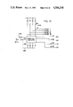
- FIG. 11 is a wiring diagram showing the preferred embodiment of the present invention.
- FIG. 11A is a schematic wiring diagram illustrating operating characteristics of the diagram shown in FIG. 11;
- FIG. 11B is a diagram similar to FIG. 11A depicting certain modifications in the circuit shown in FIG. 11 for converting the circuit from a dynamic operation to a static operation;
- FIG. 12 is a voltage graph of the circuit shown in FIG. 11;
- FIG. 13 is a partial view of an arrangement for monitoring several probes by sharing certain features of the circuit shown in FIG. 11;
- FIG. 14 is an enlarged cross-sectional view showing the preferred embodiment of the probe used in FIG. 11;
- FIG. 15 is a partially cross-sectioned view of the probe shown in FIG. 14 after it is rotated 90°.
- FIG. 1 shows a probe 10 constructed in accordance with one aspect of the invention.
- the probe which is best shown in FIGS. 3-4, 14 and 15, is mounted in a liquid receptacle illustrated as an oil pan 12 attached to the lower portion of internal engine block 14. Oil 16 in pan 12 has a level a when the engine is not operating.
- a coiled metal wire 20 is used to support probe 10 at a position in pan 12 by passing through access tube 30.
- a stop cap 32 is used to control the vertical position of probe 10.
- probe 10 includes a wire 60 formed from a positive temperature coefficient metal of the type well known in the art.
- Alloy 52 wire with a diameter approximately 3.0 mils is used.
- Alloy 52 is a nickel/iron alloy having a coefficient of approximately 3,000 PPM/C°.
- wire 60 is wrapped into elongated convolutions with legs 62a-62f which extend in a direction corresponding to the direction of change of the liquid level being sensed or monitored.
- both low and high levels are indicated.
- the liquid When probe 10 is submerged within oil 16, the liquid is above the convolutions formed by wire 60. This is the condition when sufficient oil is in the pan. If the oil level progresses downward along the convolutions of wire 60, the level of liquid or oil decreases to a value which indicates a need for additional oil. In FIG. 2, this position is illustrated as being below the wire 60; however, it can be anywhere along the wire. This feature of probe 10 allows it to be adjusted externally to control the actual low level detected by circuit 50. When a voltage is applied across leads 40, 42, current flows through wire 60. If the wire is completely submerged in liquid, the liquid dissipates the heat and maintains the temperature and thus the resistance of wire 60 relatively low.
- wire 60 As the oil level progresses downwardly, a greater portion of wire 60 is in air. This allows heating of the exposed wire and an increased effective resistance across leads 40, 42. As the oil level drops, the resistance continues increasing. Larger portions of wire 60 are in the air. Heat caused by current flow through the wire actually heats the wire. The sensed voltage across wire 60 is used to create a warning light when the level of the oil reaches a preselected lower position as detected by the effective resistance of wire 60 between leads 40, 42.
- probe 10 can be used in a plurality of reservoirs or receptacles in a motor vehicle.
- transmission pan 70 has a liquid 72 with a level b to be monitored by a probe connected to circuit 50.
- probe 10 can be used to measure the level c of fluid 82 in differential housing 80. All of these probes can be monitored by circuit 50 by multiplexing or using parallel components. The latter scheme is shown in FIG. 13.
- circuit 50 creates a signal in the detect circuit 52 which actuates one of the warning lights L1, L2 or L3.
- FIG. 3 is illustrative in nature and indicates that probe 10 can be used in several locations and can be monitored by a single control circuit.
- plastic insulation member 100 is releasably secured to plastic member 102 by two prongs 110, 112 fixed within member 100. These prongs are receivable by connector sleeves 114, 116 to form an electrical connection with leads 40, 42.
- the hard plastic support frame 120 with ends 122, 124 and an upper support bar 130 is secured onto or abuts member 100.
- Wire 60 is wrapped endwise around ends 122, 124 which are spaced from each other a distance of about 1.0 inch.
- Notches 132 receive wire 60 to form the convolutions and to maintain the wire convolutions spaced from each other.
- wire 60 The ends of wire 60 are wrapped around and soldered to prongs 110, 112 at joints 134, 136.
- a cylindrical metal casing 140 has two crimped ears 142, 144 to hold rigid frame 120 in the casing. Spaced holes 150 allow for release of air as the casing 140 fills with oil.
- the effective resistance across prongs 110, 112 changes according to the temperature of wire 60. This change in resistance is used in control circuit 50 in a manner to be discussed later.
- control circuit 50 is shown as a static circuit 200 where the level is measured only when the vehicle is first started. This is the most common mode of operation; however, a dynamic operation is possible wherein the level is monitored periodically.
- Circuit 200 includes a power supply 202 with a 8.2 volts Zener diode 203 for creating a control voltage V CC when the ignition switch 204 is closed. This voltage is usually 8.2 volts unless the battery voltage is lower than 8.2 volts.
- the main circuit includes a first switching means, shown as transistor 210. When this transistor is conducting, current flows through resistor 212, line 214 and wire 60. This current flow heats wire 60 in accordance with the amount of exposed wire.
- a one shot device 220 has an output 222 which is low for a cycle duration determined by values of C1, R1. In practice, this time duration is 200-500 milliseconds and is the measuring cycle for the control circuit.
- output 222 shifts to a logic zero, transistor 210 conducts to pass current through wire 60 of probe 10.
- the condition of the probe is detected or measured from control point 230 which is connected to ground through resistors 232, 234 and 236 by a circuit that includes main control capacitor 240.
- control capacitor 240 also C2 will be charged at a relatively slow rate which would be affected by the ambient temperature of wire 60 when transistor 210 is turned on.
- capacitor 240 is grounded during the initial part of the measuring cycle controlled by one shot device 220. Grounding of capacitor 240 through diode 242 is accomplished by a second one shot device 244 having an output 246. This output shifts to a logic zero, i.e. low voltage, for approximately 15-30 ms. As so far described, closing switch 204 creates voltage V CC which controls one shot devices 220, 244 to start a measuring or sampling cycle. Switching device or transistor 210 is switched immediately. In a like manner, capacitor 240 is immediately grounded through diode 242. After a short time (15-30 ms), diode 242 is reversed biased by a change in condition of output 246.
- Transistor 210 continues to conduct for the remainder of the measuring cycle, i.e. 200-500 ms. This allows capacitor 240 to be brought to the ambient condition of wire 60 before capacitor 240 is used to monitor the voltage and/or resistance of wire 60.
- This monitoring action is accomplished by a signal creating detector 250 having a transistor 252 coupled to the V CC voltage by resistor 254. The base of transistor 252 is connected to control point 253 so that the conduction of transistor 252 follows the voltage at this point. This voltage also corresponds with the voltage variations across wire 60 of probe 10.
- Schmidt trigger 256 is actuated. This causes holding or latch circuit 260 to be tripped by the signal on line 258.
- Reset line 264 is connected to the output 246 of one shot 244 for the purpose of resetting holding or latch circuit 260 at the start of each measuring cycle.
- warning light L1 is actuated by current passage through transistor 266.
- switch 204 In operation of the control circuit 200 shown in FIG. 8, when the vehicle is started, switch 204 is closed. This immediately creates voltage V CC corresponding to the battery voltage of the vehicle. This actuates Schmidt trigger 1A of one shot device 220 to cause a low voltage in output line 222. This low voltage is applied to the base of transistor 210 to cause a voltage across wire 60 so that a heating current flows through resistor 212 and wire 60. At the same time, capacitor C3 of one shot device 244 is pulled upward. This causes a low voltage or logic zero in output line 246. Thus, the main control capacitor 240 is grounded and charged rapidly through resistors 212, 232 to a voltage corresponding with the probe voltage.
- Resistors 212, 232 provide a low time constant and the rapid charging of capacitor 240. After a short time, such as 15-30 ms, Schmidt trigger 1B shifts to a high logic in output 246. This blocks current flow through diode 242 and places control capacitor 240 in a charging circuit including resistors 234, 236 having higher resistances. Consequently, capacitor 240 now has a relatively high time constant so that it is charged slowly and follows the voltage across probe 10. If wire 60 of probe 10 is within the liquid a sufficient amount, the wire does not heat beyond a preselected amount. This causes the voltage to stabilize and the voltage across capacitor 240 to also stabilize. This condition is shown generally in FIG. 9 wherein the voltage on capacitor 240 is plotted as a function of time.
- the upper dash line is a theshold voltage which will cause creation of a warning signal.
- Time t 1 represents the time at which one shot device 244 connects capacitor 240 to ground. As can be seen in FIG. 9, the voltage across capacitor 240 does not build up to a value exceeding the threshold voltage. No detection is made. This is the normal operating condition for the system. If sufficient amount of wire 60 is out of liquid to indicate a low level, capacitor 240 continues to charge after t 1 , as shown in FIG. 10. At a time t A , the capacitor voltage exceeds the threshold voltage and a warning signal is created.
- main probe circuit C includes a first switching means or transistor 300 and a resistor 302 having a low resistance. This causes a high current flow through wire 60 when 12 volts is applied by switch line SW and through diode D1. At the same time, the V CC voltage is created. This voltage is tied to an 8.2 volt value by Zener diode ZD1.
- Basic control capacitor 310 corresponds with previously discussed capacitor 240. This control capacitor is generally in series with resistors 312, 314 and 316. Resistor 316 is relatively large for the purpose of bleeding current from the system to prevent a gradual build up of voltage across capacitor 310 during continuous operation of the control circuit C.
- Control point B generally follows the voltage drop across wire 60 of probe 10 as previously described.
- the second switching means in circuit C is transistor 320 which is turned on for 15-20 milliseconds by timing circuit 330 at the beginning of a probe measuring cycle.
- Timer or timing circuit 330 corresponds generally to one shot 244 shown in FIG. 8 and includes input 332 and output 334.
- switch means 320 When the logic on line 334 goes high, switch means 320 is energized to ground capacitor 310.
- input 332 is connected to the output of an oscillator 340 which has an output line 342 that shifts to a logic one periodically. In practice, this shift occurs after about 15 seconds to create actuating pulses.
- switch 320 is turned on to ground control capacitor 310 so that the capacitor is charged to the ambient condition of probe 10.
- a pulse in output 342 also actuates a second timer 350 having an output 352. This timer corresponds with one shot device 220 of FIG. 8 and is used to control the total measuring or sampling cycle.
- an intermediate transient protecting transistor 360 is used in circuit C. Zener diode 362 and resistor 364 assures that transistor 360 is on during high voltage conditions. When transistor 360 is on, transistor 300 is off. During normal conditions, transistor 360 is biased OFF during the timing pulse in line 342. Consequently, transistor 300 is biased ON during this measuring or sampling cycle.
- the cycle duration is 300 milliseconds or over ten times the duration of the conducting period for transistor 320. It is noted that in this embodiment switching means or transistor 320 grounds capacitor 310 directly to circuit ground. This assures a rapid pull down of point B to provide the initial voltage on capacitor 310 at the start of a sampling or measuring cycle.
- Oscillator 340 causes a sampling of the voltage across wire 60 each 15 seconds by creating a pulse in line 342. During each sampling period or cycle, transistor 320 grounds capacitor 310 for approximately 15-20 milliseconds. At the same time, switching device 300 is passing current through probe 10. This main current flow lasts for 300 milliseconds. If a sufficient amount of the wire on the probe is in air, the voltage point B continues to rise after transistor 320 is turned off. When the voltage rises a sufficient amount to indicate a low level in the receptacle being monitored by probe 10, comparator 370 is toggled. This comparator has a non-inverting input 372 controlled by a fixed reference voltage, in practice about 500 mv.
- circuit C is a dynamic circuit that monitors the condition of probe 10 periodically during operation of the vehicle. This is accomplished by oscillator 340 creating starting pulses each 15 seconds. These starting pulses each create a measuring or sampling cycle by actuating one shot device 330 to ground capacitor 310 and to actuate one shot device 350 to apply voltage across probe 10. This concept of both one shot devices operated in unison by oscillator 340 is shown generally in FIG. 11A. The resulting voltage at point B is shown in the graph of FIG. 12. If the resistance across wire 60 indicates a sufficient liquid level in the receptacle being monitored, the voltage at point B never reaches a value sufficient to toggle holding circuit 380. This is shown at the left of FIG. 12. At the right of FIG.
- Holding circuit 380 could be various circuits; however, in practice a feedback circuit includes resistor R19 and diode D5. A noise suppressing capacitor CB is used with a clamping diode D7.
- the logic in line 392 is a high logic during the initial portion of the timing cycle to reset holding circuit 380 and maintain it reset until after initial charging of capacitor 310.
- an override circuit 396 which includes a one shot device to create a high blocking logic in line 394 for a substantial amount of time.
- This high logic in line 394 prevents operation of holding circuit 380 for a given interval which, in practice, is one minute.
- lamp L1 can not be operated because of low battery voltage that may occur when the starter of a vehicle is being operated.
- Circuit C can be modified from a dynamic circuit operating continuously as schematically illustrated in FIG. 11A to a static circuit by slight modifications as schematically represented in FIG. 11B.
- the static control circuit C' does not include overriding circuit 396.
- Resistor R23 of oscillator 340 is connected to voltage V CC through a forward bias diode 398. In this manner, oscillator 340 is converted to a one shot device.
- a resistor RX is placed at the position indicated as RX in FIG. 11. This causes capacitor C1 to discharge slowly.
- the device C' will not operate until a preselected period after the engine has been turned off. This allows the oil to drain back into the pan.
- the circuit will not operate until 2-3 minutes have elapsed.
- circuit C can be converted into a static circuit C'.
- a one shot device could be placed before one shot device 220 in FIG. 8. This additional one shot device would assure that the oil is in a static condition before starting the measuring cycle.
- the modified input circuit does not cause a delay.
- capacitor C1 has had time to discharge, an immediate pulse is provided to the input of one shot device 350.
- the modification to the input side of the circuit becomes a factor only when the engine has not been turned off a preselected amount of time determined by the discharge through resistor RX as shown in FIG. 11B. In that instance, the circuit does not create a measuring cycle that could give a misleading result.
- FIG. 13 there is a schematic circuit that uses several probes (I-IV). These probes can be monitored by the same circuit as shown in FIG. 11.
- each circuit shares components, such as one shot device 330. It is intended that such common use of the circuit components for the purpose of monitoring more than one probe 10 can be done as shown in FIG. 13.
- a multiplexing arrangement can be used by inputting information to a single circuit C from different probes on a time share basis to control different lights. This would be true multiplexing of the control system for several probes.
- a modified probe 400 is shown in FIGS. 14 and 15. This probe is the preferred embodiment.
- Probe 400 is similar to probe 10; however, it includes a threaded base 402 screwed into a threaded aperture 404 at the lower wall 406 of the receptacle to be monitored.
- Wrench receiving head 410 of base 402 supports outwardly extending leads 40, 42 extending from internal wire 60 generally as described with regard to probe 10.
- a gasket 412 seals aperture 404 after probe 400 has been installed within the receptacle.
- a nose 420 receives an upwardly extending sleeve 422 having outwardly directed holes 430 near nose 420.
- An internal plastic frame 440 is used to support wire 60 in a plurality of convolutions extending generally in the vertical direction. The ends of wire 60 are connected at junctions 442, 444 to complete an electrical circuit through prongs 460, 462 that are attached by standard connectors onto the ends of leads 40, 42.
- Sleeve 422 prevents splashing of oil onto
- FIGS. 8 and 11 Components of the circuit shown in FIGS. 8 and 11 can be interchanged to perform the same functions. Even though wire 60 is shown with its legs vertically, it can be mounted in the receptacle with the legs horizontal.
- the voltage graphs in FIGS. 9, 10 and 12 show that the control capacitors charge slightly after the ground condition is terminated; however, the ground is for a sufficient time to bring the capacitor rapidly to a voltage representing the ambient condition of the probe.
Abstract
Description
Claims (43)
Priority Applications (2)
| Application Number | Priority Date | Filing Date | Title |
|---|---|---|---|
| US06/380,429 US4506258A (en) | 1982-05-20 | 1982-05-20 | System for detecting low liquid level and probe therefor |
| US06/678,589 US4591839A (en) | 1982-05-20 | 1984-12-05 | System for detecting low liquid level and probe therefor |
Applications Claiming Priority (1)
| Application Number | Priority Date | Filing Date | Title |
|---|---|---|---|
| US06/380,429 US4506258A (en) | 1982-05-20 | 1982-05-20 | System for detecting low liquid level and probe therefor |
Related Child Applications (1)
| Application Number | Title | Priority Date | Filing Date |
|---|---|---|---|
| US06/678,589 Division US4591839A (en) | 1982-05-20 | 1984-12-05 | System for detecting low liquid level and probe therefor |
Publications (1)
| Publication Number | Publication Date |
|---|---|
| US4506258A true US4506258A (en) | 1985-03-19 |
Family
ID=23501131
Family Applications (1)
| Application Number | Title | Priority Date | Filing Date |
|---|---|---|---|
| US06/380,429 Expired - Fee Related US4506258A (en) | 1982-05-20 | 1982-05-20 | System for detecting low liquid level and probe therefor |
Country Status (1)
| Country | Link |
|---|---|
| US (1) | US4506258A (en) |
Cited By (20)
| Publication number | Priority date | Publication date | Assignee | Title |
|---|---|---|---|---|
| US4583085A (en) * | 1985-01-18 | 1986-04-15 | The Singer Company | Liquid level sensor assembly |
| US4654646A (en) * | 1985-02-22 | 1987-03-31 | Wickes Manufacturing Company | Modular liquid level sensor having integral electronics |
| US4771271A (en) * | 1987-03-11 | 1988-09-13 | Ford Motor Company | Silicon based low level liquid sensor having a fast response time |
| US4799047A (en) * | 1986-12-17 | 1989-01-17 | Nippondenso Co., Ltd. | Liquid level detecting and indicating system with coil type measuring device |
| US4988975A (en) * | 1987-12-14 | 1991-01-29 | Nap Kimbel A | Dip stick resistive liquid level detector with adjustable stop |
| US5057813A (en) * | 1989-05-25 | 1991-10-15 | Fuji Jukogyo Kabushiki Kaisha | Oil level sensor for an internal combustion engine |
| US5205172A (en) * | 1991-09-23 | 1993-04-27 | Doak Roni K | Electronic gauge for interface measurements |
| US5267474A (en) * | 1992-10-23 | 1993-12-07 | Kohler Co. | Liquid-level sensor |
| US6239709B1 (en) | 1999-02-18 | 2001-05-29 | Briggs & Stratton Corporation | Liquid level sensor for internal combustion engine |
| US6588270B1 (en) * | 1999-11-17 | 2003-07-08 | Mannesmann Vdo Ag | Filling level indicator for a washer fluid container |
| US6617968B1 (en) * | 2000-10-24 | 2003-09-09 | Dana Corporation | Capacitive oil level sensor for vehicular drive axles |
| US20060277992A1 (en) * | 2005-06-08 | 2006-12-14 | Calabrese Ronald V | Self-Calibrating Liquid Level Transmitter |
| EP2216610A1 (en) * | 2009-02-06 | 2010-08-11 | Cotherm | Thermosensitive sensor for hot water tank |
| CN101819055A (en) * | 2010-05-14 | 2010-09-01 | 浙江苏泊尔家电制造有限公司 | Liquid level detection device |
| CN101368838B (en) * | 2008-07-25 | 2011-10-05 | 陈建海 | Water level sensor for automobile and its control method |
| US20130030677A1 (en) * | 2010-03-09 | 2013-01-31 | Wacker Neuson Produktion GmbH & Co. KG | Drive system with an apparatus for interrupting the operation in the case of an imminent lack of operating medium |
| US20140091938A1 (en) * | 2012-07-09 | 2014-04-03 | David B. Nirenberg | Depth Guide System for Use With Watercraft Trailers, Lifts, and the Like |
| US20160084695A1 (en) * | 2014-09-23 | 2016-03-24 | Caterpillar Inc. | System and method of monitoring oil level in transmission system of machine |
| US20160377588A1 (en) * | 2015-06-29 | 2016-12-29 | Hella Kgaa Hueck & Co. | Sensor device for determining the evaporation pressure of a fluid, in particular of a fluidic fuel |
| US11614354B2 (en) | 2018-02-13 | 2023-03-28 | Renk America Llc | Dipstick and electronic fluid level sensor |
Citations (18)
| Publication number | Priority date | Publication date | Assignee | Title |
|---|---|---|---|---|
| US2337608A (en) * | 1942-04-18 | 1943-12-28 | Universal Oil Prod Co | Liquid level indicator |
| US2499575A (en) * | 1947-07-15 | 1950-03-07 | Bristol Company | Submersible electrical resistance thermometer |
| US2612047A (en) * | 1949-02-10 | 1952-09-30 | Anemostat Corp America | Probe device for fluid condition measuring apparatus |
| US2742634A (en) * | 1953-07-21 | 1956-04-17 | Republic Aviat Corp | Supervisory circuit for ambient condition detector |
| US2804517A (en) * | 1954-02-06 | 1957-08-27 | Jean Billarant | Oil level indicator |
| US2901740A (en) * | 1956-11-23 | 1959-08-25 | Specialties Dev Corp | Electrical network automatically responsive to a change in condition |
| US3350710A (en) * | 1964-04-28 | 1967-10-31 | Dipstix Ltd | Liquid level indicators |
| US3376568A (en) * | 1964-09-29 | 1968-04-02 | Gen Motors Corp | Transistor switching circuit |
| US3547145A (en) * | 1966-05-16 | 1970-12-15 | Walter Holzer | Apparatus for sensing levels in containers holding liquids |
| US3740740A (en) * | 1972-01-12 | 1973-06-19 | Us Army | Liquid cryogen detector |
| US3911744A (en) * | 1974-04-10 | 1975-10-14 | Liquidometer Corp | Liquid level gauging apparatus |
| US3943767A (en) * | 1974-07-22 | 1976-03-16 | American Magnetics, Inc. | Level detector system for cryogenic liquids |
| US4072053A (en) * | 1975-11-05 | 1978-02-07 | Anderson Stig Lennart | Apparatus for indicating liquid level in a receptacle |
| US4102191A (en) * | 1976-11-19 | 1978-07-25 | Harris Roger J | Digital fuel gauge |
| US4163391A (en) * | 1976-10-06 | 1979-08-07 | Jaeger | Device for checking the level of a liquid in a tank |
| US4185207A (en) * | 1977-08-15 | 1980-01-22 | Ab Svensk Nivakontroll | Amplifier system with alternate inputs |
| US4283719A (en) * | 1978-08-23 | 1981-08-11 | Lucas Industries Limited | Liquid level sensing circuit |
| US4361038A (en) * | 1980-12-01 | 1982-11-30 | General Dynamics Corporation | Liquid level sensor |
-
1982
- 1982-05-20 US US06/380,429 patent/US4506258A/en not_active Expired - Fee Related
Patent Citations (18)
| Publication number | Priority date | Publication date | Assignee | Title |
|---|---|---|---|---|
| US2337608A (en) * | 1942-04-18 | 1943-12-28 | Universal Oil Prod Co | Liquid level indicator |
| US2499575A (en) * | 1947-07-15 | 1950-03-07 | Bristol Company | Submersible electrical resistance thermometer |
| US2612047A (en) * | 1949-02-10 | 1952-09-30 | Anemostat Corp America | Probe device for fluid condition measuring apparatus |
| US2742634A (en) * | 1953-07-21 | 1956-04-17 | Republic Aviat Corp | Supervisory circuit for ambient condition detector |
| US2804517A (en) * | 1954-02-06 | 1957-08-27 | Jean Billarant | Oil level indicator |
| US2901740A (en) * | 1956-11-23 | 1959-08-25 | Specialties Dev Corp | Electrical network automatically responsive to a change in condition |
| US3350710A (en) * | 1964-04-28 | 1967-10-31 | Dipstix Ltd | Liquid level indicators |
| US3376568A (en) * | 1964-09-29 | 1968-04-02 | Gen Motors Corp | Transistor switching circuit |
| US3547145A (en) * | 1966-05-16 | 1970-12-15 | Walter Holzer | Apparatus for sensing levels in containers holding liquids |
| US3740740A (en) * | 1972-01-12 | 1973-06-19 | Us Army | Liquid cryogen detector |
| US3911744A (en) * | 1974-04-10 | 1975-10-14 | Liquidometer Corp | Liquid level gauging apparatus |
| US3943767A (en) * | 1974-07-22 | 1976-03-16 | American Magnetics, Inc. | Level detector system for cryogenic liquids |
| US4072053A (en) * | 1975-11-05 | 1978-02-07 | Anderson Stig Lennart | Apparatus for indicating liquid level in a receptacle |
| US4163391A (en) * | 1976-10-06 | 1979-08-07 | Jaeger | Device for checking the level of a liquid in a tank |
| US4102191A (en) * | 1976-11-19 | 1978-07-25 | Harris Roger J | Digital fuel gauge |
| US4185207A (en) * | 1977-08-15 | 1980-01-22 | Ab Svensk Nivakontroll | Amplifier system with alternate inputs |
| US4283719A (en) * | 1978-08-23 | 1981-08-11 | Lucas Industries Limited | Liquid level sensing circuit |
| US4361038A (en) * | 1980-12-01 | 1982-11-30 | General Dynamics Corporation | Liquid level sensor |
Non-Patent Citations (2)
| Title |
|---|
| Tarpley, R. W. et al., Solid State Automotive Liquid Level Sensing System, SAE publication 800127, pp. 97 100. * |
| Tarpley, R. W. et al., Solid-State Automotive Liquid Level Sensing System, SAE publication 800127, pp. 97-100. |
Cited By (30)
| Publication number | Priority date | Publication date | Assignee | Title |
|---|---|---|---|---|
| US4583085A (en) * | 1985-01-18 | 1986-04-15 | The Singer Company | Liquid level sensor assembly |
| US4654646A (en) * | 1985-02-22 | 1987-03-31 | Wickes Manufacturing Company | Modular liquid level sensor having integral electronics |
| US4799047A (en) * | 1986-12-17 | 1989-01-17 | Nippondenso Co., Ltd. | Liquid level detecting and indicating system with coil type measuring device |
| US4771271A (en) * | 1987-03-11 | 1988-09-13 | Ford Motor Company | Silicon based low level liquid sensor having a fast response time |
| US4988975A (en) * | 1987-12-14 | 1991-01-29 | Nap Kimbel A | Dip stick resistive liquid level detector with adjustable stop |
| WO1992010821A1 (en) * | 1987-12-14 | 1992-06-25 | Nap Kimbel A | Dip stick resistive liquid level detector with adjustable stop |
| US5057813A (en) * | 1989-05-25 | 1991-10-15 | Fuji Jukogyo Kabushiki Kaisha | Oil level sensor for an internal combustion engine |
| US5205172A (en) * | 1991-09-23 | 1993-04-27 | Doak Roni K | Electronic gauge for interface measurements |
| US5267474A (en) * | 1992-10-23 | 1993-12-07 | Kohler Co. | Liquid-level sensor |
| US6239709B1 (en) | 1999-02-18 | 2001-05-29 | Briggs & Stratton Corporation | Liquid level sensor for internal combustion engine |
| US6588270B1 (en) * | 1999-11-17 | 2003-07-08 | Mannesmann Vdo Ag | Filling level indicator for a washer fluid container |
| US6617968B1 (en) * | 2000-10-24 | 2003-09-09 | Dana Corporation | Capacitive oil level sensor for vehicular drive axles |
| US20070295056A1 (en) * | 2005-06-08 | 2007-12-27 | Calabrese Ronald V | Self-calibrating liquid level transmitter |
| US7284427B2 (en) | 2005-06-08 | 2007-10-23 | Lumenite Control Technology, Inc. | Self-calibrating liquid level transmitter |
| US20060277992A1 (en) * | 2005-06-08 | 2006-12-14 | Calabrese Ronald V | Self-Calibrating Liquid Level Transmitter |
| US7461550B2 (en) | 2005-06-08 | 2008-12-09 | Lumenite Control Technology, Inc. | Self-calibrating liquid level transmitter |
| US20090064757A1 (en) * | 2005-06-08 | 2009-03-12 | Lumenite Control Technology, Inc. | Self-calibrating liquid level transmitter |
| US7665358B2 (en) | 2005-06-08 | 2010-02-23 | Lumenite Control Technology, Inc. | Self-calibrating liquid level transmitter |
| CN101368838B (en) * | 2008-07-25 | 2011-10-05 | 陈建海 | Water level sensor for automobile and its control method |
| FR2942026A1 (en) * | 2009-02-06 | 2010-08-13 | Cotherm Sa | THERMOSENSIBLE SENSOR FOR HOT WATER STORAGE BALLOON |
| EP2216610A1 (en) * | 2009-02-06 | 2010-08-11 | Cotherm | Thermosensitive sensor for hot water tank |
| US20130030677A1 (en) * | 2010-03-09 | 2013-01-31 | Wacker Neuson Produktion GmbH & Co. KG | Drive system with an apparatus for interrupting the operation in the case of an imminent lack of operating medium |
| CN101819055A (en) * | 2010-05-14 | 2010-09-01 | 浙江苏泊尔家电制造有限公司 | Liquid level detection device |
| US20140091938A1 (en) * | 2012-07-09 | 2014-04-03 | David B. Nirenberg | Depth Guide System for Use With Watercraft Trailers, Lifts, and the Like |
| US9127940B2 (en) * | 2012-07-09 | 2015-09-08 | Lake Red Rock Llc | Depth guide system for use with watercraft trailers, lifts, and the like |
| US20160084695A1 (en) * | 2014-09-23 | 2016-03-24 | Caterpillar Inc. | System and method of monitoring oil level in transmission system of machine |
| US9593974B2 (en) * | 2014-09-23 | 2017-03-14 | Caterpillar Inc. | System and method of monitoring oil level in transmission system of machine |
| US20160377588A1 (en) * | 2015-06-29 | 2016-12-29 | Hella Kgaa Hueck & Co. | Sensor device for determining the evaporation pressure of a fluid, in particular of a fluidic fuel |
| CN106286029A (en) * | 2015-06-29 | 2017-01-04 | 赫拉胡克公司 | For determining the sensor device of the pressure for vaporization of fluid, especially fuel liquid |
| US11614354B2 (en) | 2018-02-13 | 2023-03-28 | Renk America Llc | Dipstick and electronic fluid level sensor |
Similar Documents
| Publication | Publication Date | Title |
|---|---|---|
| US4591839A (en) | System for detecting low liquid level and probe therefor | |
| US4506258A (en) | System for detecting low liquid level and probe therefor | |
| US4720997A (en) | Material level monitor | |
| US5521581A (en) | Fluid level and temperature monitor and alarm system for an automobile cooling system | |
| US5656771A (en) | Motor vehicle cooling system status indicator | |
| US4326199A (en) | Autoreferencing liquid level sensing apparatus and method | |
| US6477478B1 (en) | Method and apparatus for automotive and other testing | |
| US4476714A (en) | Engine oil level sensor | |
| EP0191348A2 (en) | An adaptive glow plug controller | |
| JPH02504562A (en) | Control and monitoring circuits especially for electrical seat heating means in motor vehicles | |
| US4988975A (en) | Dip stick resistive liquid level detector with adjustable stop | |
| KR960040771A (en) | Diagnostic Detection Device and Method for Hall Effect Digital Tooth Sensor | |
| US4221125A (en) | Apparatus and method for detecting the presence of a substance on a liquid surface | |
| US4450719A (en) | Air flow meter | |
| GB2353601A (en) | Automotive testing | |
| US4584554A (en) | Engine oil level detecting device | |
| DE4315519C2 (en) | Liquid level measuring device | |
| US4656464A (en) | Liquid level detector | |
| US4322713A (en) | Level monitoring methods and apparatus particularly for high-resistivity liquids | |
| US4283719A (en) | Liquid level sensing circuit | |
| US3350710A (en) | Liquid level indicators | |
| US5136275A (en) | Ground connection monitoring for airbag electrical igniter circuit | |
| US4702620A (en) | Methods of and apparatus for testing internal combustion engines by monitoring the cooling systems thereof | |
| CA1244108A (en) | Low liquid level sensing and warning circuit | |
| DE10209436A1 (en) | Device for detecting, monitoring, influencing electric iron operating state has power switch controlled by control unit to perform emergency or safety cut-off depending on iron operating state |
Legal Events
| Date | Code | Title | Description |
|---|---|---|---|
| AS | Assignment |
Owner name: GULF & WESTERN MANUFACTURING COMPANY 26261 EVERGRE Free format text: ASSIGNMENT OF ASSIGNORS INTEREST.;ASSIGNORS:CHARBONEAU, BEN J.;ZEROD, RICHARD D.;REEL/FRAME:004001/0376 Effective date: 19820517 Owner name: GULF & WESTERN MANUFACTURING COMPANY, A CORP. OF D Free format text: ASSIGNMENT OF ASSIGNORS INTEREST;ASSIGNORS:CHARBONEAU, BEN J.;ZEROD, RICHARD D.;REEL/FRAME:004001/0376 Effective date: 19820517 |
|
| AS | Assignment |
Owner name: WICKES MANUFACTURING COMPANY Free format text: CHANGE OF NAME;ASSIGNOR:GULF & WESTERN MANUFACTURING COMPANY;REEL/FRAME:004537/0697 Effective date: 19850926 |
|
| FEPP | Fee payment procedure |
Free format text: PAYOR NUMBER ASSIGNED (ORIGINAL EVENT CODE: ASPN); ENTITY STATUS OF PATENT OWNER: LARGE ENTITY |
|
| FPAY | Fee payment |
Year of fee payment: 4 |
|
| AS | Assignment |
Owner name: TRW INC., A CORP. OF OH, OHIO Free format text: ASSIGNMENT OF ASSIGNORS INTEREST.;ASSIGNOR:WICKES MANUFACTURING COMPANY;REEL/FRAME:005366/0975 Effective date: 19900402 |
|
| REMI | Maintenance fee reminder mailed | ||
| LAPS | Lapse for failure to pay maintenance fees | ||
| STCH | Information on status: patent discontinuation |
Free format text: PATENT EXPIRED DUE TO NONPAYMENT OF MAINTENANCE FEES UNDER 37 CFR 1.362 |