US4506359A - TASI Apparatus for use with systems having interregister multifrequency signalling - Google Patents
TASI Apparatus for use with systems having interregister multifrequency signalling Download PDFInfo
- Publication number
- US4506359A US4506359A US06/410,596 US41059682A US4506359A US 4506359 A US4506359 A US 4506359A US 41059682 A US41059682 A US 41059682A US 4506359 A US4506359 A US 4506359A
- Authority
- US
- United States
- Prior art keywords
- interregister
- delay
- signals
- transmission
- applying
- Prior art date
- Legal status (The legal status is an assumption and is not a legal conclusion. Google has not performed a legal analysis and makes no representation as to the accuracy of the status listed.)
- Expired - Fee Related
Links
Images


Classifications
-
- H—ELECTRICITY
- H04—ELECTRIC COMMUNICATION TECHNIQUE
- H04J—MULTIPLEX COMMUNICATION
- H04J3/00—Time-division multiplex systems
- H04J3/17—Time-division multiplex systems in which the transmission channel allotted to a first user may be taken away and re-allotted to a second user if the first user becomes inactive, e.g. TASI
Definitions
- the present invention relates to telecommunications apparatus generally and more particularly to time assignment speech interpolation apparatus
- Time Assignment Speech interpolation (TASI) communication systems have been known for approximately twenty years. Their function, stated in general terms, is to exploit the fact that during a normal telephone conversation, information is being transmitted only about 35% of the time. TASI communication systems serve to connect a speaker to a transmission line only during those portions of a conversation when speech is actually present. During the other portions of the conversation, the transmission line is connected to another speaker, currently speaking in another conversation. By using time assignment speech interpolation, a given number of transmission lines, such as 24, can usually carry about 48 simultaneous conversations.
- TASI system which has met with commercial success is currently manufactured by Electronics Corporation of Israel Ltd. and is described in Published European Patent Application No. 0025465 of Mar. 25, 1981 corresponding to application No. 79301917.5.
- Interregister multi frequency signalling is known as System R-2 line signalling in the CCITT standards and Socotel in the French system.
- the R 2 system operation is described in detail in Volume VI.3 of the CCITT standards, Orange Book, Section 2, Recommendations Q 411-Q 416, the contents of which are incorporated herein by reference as background source material.
- the R 2 system involves an in-band multifrequency code with forward and backward fully compelled signalling, for call set up control signals, i.e. interregister signalling.
- Line signalling is provided by out of band signalling such as E and M wire signalling and only indicates the change of states from one signalling state to another. For example, the transition from the "idle" state to the "seized” state is indicated by an out of band transition from TONE-OFF on the outgoing line and an unchanged TONE-ON status on the incoming line.
- a number of functions of time assignment speech interpolation systems are incompatible with interregister multifrequency signalling.
- the use of an Echo Suppressor during signalling has been found by applicants to at least partially block the interregister signalling due to the simultaneous presence of signals in both directions.
- Applicants have also been found that the provision of a 6 db attenuation as part of the echo suppression in the receiver interferes with signalling receipt in the R-2 signalling protocol.
- TASI apparatus acts to extend the time-out period assigned to fully compelled interregister multifrequency signalling in the R-2 protocol.
- the present invention seeks to provide apparatus for use with a TASI system for enabling it to function in a telephone network employing fully compelled interregister multifrequency signalling such as R-2.
- transmission apparatus at a first end of a transmission trunk link having a first plurality of communication channels, the transmission apparatus including apparatus for detecting signals on a second plurality of telephone communication lines and for assigning each telephone communication line on whch signals are present to an available one of the first plurality of communication channels and apparatus for applying a delay to the detected signals;
- receiving apparatus at a second end of the transmission link including apparatus for assigning each of the first plurality of communication channels carrying signals to a corresponding one of the second plurality of telephone communication lines in accordance with assignment information received from the transmission apparatus, echo suppression apparatus, attenuation apparatus and apparatus for applying a delay to the received signals;
- apparatus for disabling at least one of following in response to the sensed onset of interregister multifrequency signalling: the apparatus for applying a delay to the detected signals, the echo suppression apparatus, the attenuation apparatus and the apparatus for applying a delay to the received signals.
- the apparatus for disabling is operative in response to the sensed onset of interregister multifrequency signalling to disable all of the following apparatus for the duration of the multifrequency signalling: apparatus for applying a delay to the detected signals, the echo suppression apparatus, the attenuation apparatus and the apparatus for applying a delay to the received signals.
- apparatus for enabling TASI operation in a network employing interregister multifrequency signalling comprising:
- apparatus for disabling at least one or all of the following apparati in response to the sensed onset of interregister multifrequency signalling apparatus for applying a delay to the detected signals, echo suppression apparatus, attenuation apparatus and apparatus for applying a delay to the received signals.
- FIGS. 1a and 1b are block diagram illustrations of time assignment speech interpolation apparatus constructed and operative in accordance with a preferred embodiment of the present invention
- FIGS. 2a and 2b are block diagram illustrations of transmit speech flow circuitry forming part of the apparatus of FIGS. 1a and 1b;
- FIGS. 3a and 3b are block diagram illustrations of receive speech flow circuitry forming part of the circuitry of FIGS. 1a and 1b;
- FIGS. 4a and 4b are a timing diagram illustrating timing for the receive speech flow circuitry of FIGS. 3a and 3b;
- FIGS. 5A through 5K are schematic illustration of echo suppression circuitry forming part of the apparatus of FIGS. 1a and 1b;
- FIGS. 6A through 6M are schematic illustration of transmit speech flow circuitry illustrated in block diagram form in FIGS. 2a and 2b;
- FIGS. 7A through 7H are schematic illustration of receive speech flow circuitry illustrated in block diagram form in
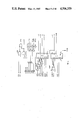
- FIG. 1 illustrates TASI circuitry suitable for use in telephone networks having fully compelled interregister multifrequency signalling constructed and operative in accordance with an embodiment of the present invention.
- the apparatus of FIG. 1 comprises an input circuit 10, which may be similar to the circuitry illustrated in FIG. 2A of the above cited published European Patent Application.
- Circuit 10 receives inputs from telephone communications lines which are typically dedicated to outgoing calls.
- the output of circuit 10 is supplied to transmit speech flow circuitry 12, which receives an input from an CPU 14 and provides an output to a transmit audio switch 16.
- Circuitry 12 will be described in detail hereinafter in connection with FIG. 2.
- Audio switch 16 receives an input from a message transmit circuit 18, which also receives an input from CPU 14.
- the output of audio switch 16 is supplied via an output circuit 20 to an available one of the communication channels in accordance with general TASI principles.
- the output of input circuit 10 is also supplied to speech detector circuitry 17 which receives an input from an echo suppressor 19. Both the echo suppressor and the speech detector interface with the CPU 14.
- CPU 14 also receives an input from a signal detector 21, which in turn receives an input from the M signalling wire via an input circuit 23. Activity on the M signalling wire indicates initiation of a call.
- the communication channels are coupled to an input circuit 22, which outputs to a receive speech flow circuit 24 which receives an input from a CPU 15.
- Receive speech flow circuit 24 will be described in detail hereinafter in connection with FIG. 3.
- the output of circuit 24 is supplied to a message receiver circuit 26, which outputs to the CPU 15.
- the output of circuit 24 is also supplied to a receive audio switch 28, which outputs to a -6b attenuation circuit 30.
- the attenuated signal is supplied via an output circuit 32 to remote telephone communication lines which are typically dedicated to incoming calls.
- CPU 15 also provides an enable output to attenuation circuit 30. Additionally CPU 15 provides an output to a receive signalling switch 34 which outputs to a signalling output circuit 36. The output of circuit 36 is coupled to the E signalling wire.
- circuitry shown in FIG. 1 on opposite mutually remote sides of a communication trunk containing a plurality of communication channels is identical and symmetric. For that reason, the receive circuitry on the outgoing side of the circuitry will not be described, since it is identical to the receive circuitry described in connection with the incoming side. Correspondingly, the transmit circuitry on the incoming side will not be described since it is identical to the transmit circuitry described in connection with the outgoing side.
- TASI may not incorporate a receive delay and may employ echo suppression apparatus which is external to the TASI apparatus.
- FIG. 2 illustrates in detailed block diagram illustration transmit speech flow circuitry 12.
- the circuitry of FIG. 2 is substantially identical in structure and function to that illustrated in FIG. 10 of the aforesaid European Patent Application and described therein, with the exception of the following portions which will now be described in detail.
- RAM 42 is operative to store a delay disable signal from the CPU bus for one or more specific telephone communication lines indicated by an address furnished by multiplexer 40.
- the multiplexer reads into the delay memory all zeros such that the contents of the signal which are read into the delay memory are read into a location in the delay memory which is next immediately read out to latch (131), without being sequenced through 384 stages which produces the delay.
- FIG. 3 illustrates receive speech flow circuitry 24.
- the circuitry of FIG. 3 is substantially identical in structure and function to that illustrated in FIG. 12 of the aforesaid published European Patent Application and described therein, with the exception of the following portions which will now be described in detail.
- Logic circuitry 50 receives the CMR 6 and BLRX timing signals respectively from a latch 99 and blank logic circuitry 97 forming part of receive control memory circuitry shown in FIG. 29b of the aforesaid Published European Patent Application 0025465 and provides an inverse receive delay disable signal to a timing selector 52.
- Timing selector 52 receives two timing signals, t A which is the normal timing signal for operation of a receive delay memory output latch (171) and t G which is a special timing signal employed in the presence of interregister multifrequency signalling.
- Timing selector 52 is operative in response to the signal received from logic circuitry 50 to determine whether to operate latch (171) on the basis of t A or t G .
- the output timing signal in either case, is applied as a latch clock signal to latch (171).
- Logic circuitry 50 is operative to cause timing selector 52 to apply the t G timing signal to latch (171) when interregister multifrequency signalling has been indicated for a given channel at a given time.
- the t G timing is operative to provide an extra clock pulse to latch (171) immediately following read in of information from that channel into the delay memory (157). In such a way, the information from that channel is passed to the latch with substantially no delay.
- t G timing signal may be appreciated from a consideration of FIG. 4 which includes a delay memory latch clock signal. Normally the clock pulse occurs at time t A t 8 , but when delay disable is indicated, it is shifted to t G t 8 so as to follow the delay memory write enable signal which occurs at t C .
- FIGS. 5-7 are schematic illustrations of various parts of the circuitry illustrating the detailed exemplary implementation of the invention in the ECI circuitry which is disclosed and claimed in the aforesaid published European Patent Application.
- FIG. 5 is a schematic illustration of echo suppression circuitry forming part of the apparatus of FIGS. 1a and 1b.
- FIG. 6 illustrates the apparatus shown in FIGS. 2a and 2b in schematic form, while FIG. 7 is a schematic illustration of part of the circuitry shown in block diagram form in FIGS. 3a and 3b.
- signal detector circuitry 21 is operative to detect a change in the status of the M signalling wire on an outgoing communication line from idle to seized.
- the status of the E wire on the outgoing side is then checked by the receive signalling switch 34 in order to indicate the status of the M wire on the incoming side. If the M wire on the incoming side remains in the idle state, outgoing the message transmit circuitry 18 transmits an assignment message to the incoming circuitry message receiver 26. The outgoing CPU 14 then decouples the communication line on which the status change from idle to seized from speech detector control and does the same with a selected communication channel. The incoming message transmit circuit 18 transmits an acknowledge message to the outgoing side.
- the outgoing side receives the acknowledge message at message receiver 26 and in response to CPU command, transmits a delay disable message to the incoming side.
- CPU 14 at the outgoing side is then operative to disable the transmit delay in circuitry 12, to disable the operation of echo suppressor 19 and to disable the 6 db attenuation circuitry 30.
- the incoming side Upon receipt of the delay disable message, the incoming side is operative to disable its receive delay in circuitry 24 and to commence a timing period of between four and eight seconds during which interregister multifrequency signalling takes place. The incoming side then sends an assignment message via its message transmit circuitry 18. The incoming CPU 15 then disables the corresponding communication line and communication channel from speech detector control.
- the outgoing side Upon receiving the assignment message, the outgoing side sends an acknowledge message via message transmit circuitry 14.
- the incoming side is operative upon receive of the acknowledge message to send a delay disable message to the outgoing side and then to disable on the incoming side the transmit delay in circuitry 12, the echo suppressor 19 and the 6 db attenuation circuitry.
- the outgoing side is operative in response to receipt of the delay disable message to disable the receive delay in the receive speech flow circuitry 24 on the outgoing side.
- the outgoing side CPU 14 then commences a timing period of between four and eight seconds during which interregister multifrequency signalling takes place. Following the commencement of this period, the CPU sends via the message transmit circuitry 18 a communication line idle signalling status message (LSD OFF) to the incoming side.
- LSD OFF communication line idle signalling status message
- the transmit and receive delays, the echo suppressor and the -6 db attenuation on both sides are all enabled to permit time assignment speech interpolation of the speech which follows established of a connection.
Abstract
TASI apparatus suitable for use with telephone networks employing interregister multifrequency signalling comprising transmission apparatus at a first end of a transmission trunk link having a first plurality of communication channels, the transmission apparatus including means for detecting signals on a second plurality of telephone communication lines on which signals are present to an available one of the first plurality of communication channels and means for applying a delay to the detected signals, receiving apparatus at a second end of the transmission link including means for assigning each of the first plurality of communication channels carrying signals to a corresponding one of the second plurality of telephone communication lines in accordance with assignment information received from the transmission apparatus, means for communicating messages including assignment information between the transmission apparatus and the receiving apparatus, means for sensing the onset of interregister multifrequency signalling on the second plurality of telephone communication lines, and means for disabling the means for applying a delay to the detected signals in response to the sensed onset of interregister multifrequency signalling.
Description
The present invention relates to telecommunications apparatus generally and more particularly to time assignment speech interpolation apparatus
Time Assignment Speech interpolation (TASI) communication systems have been known for approximately twenty years. Their function, stated in general terms, is to exploit the fact that during a normal telephone conversation, information is being transmitted only about 35% of the time. TASI communication systems serve to connect a speaker to a transmission line only during those portions of a conversation when speech is actually present. During the other portions of the conversation, the transmission line is connected to another speaker, currently speaking in another conversation. By using time assignment speech interpolation, a given number of transmission lines, such as 24, can usually carry about 48 simultaneous conversations.
A particularly effective TASI system which has met with commercial success is currently manufactured by Electronics Corporation of Israel Ltd. and is described in Published European Patent Application No. 0025465 of Mar. 25, 1981 corresponding to application No. 79301917.5.
All known TASI systems, including that manufactured by Electronics Corporation of Israel Ltd. cannot presently be used in telephone networks having fully compelled interregister multifrequency signalling.
Interregister multi frequency signalling is known as System R-2 line signalling in the CCITT standards and Socotel in the French system. The R 2 system operation is described in detail in Volume VI.3 of the CCITT standards, Orange Book, Section 2, Recommendations Q 411-Q 416, the contents of which are incorporated herein by reference as background source material. Briefly described, the R 2 system involves an in-band multifrequency code with forward and backward fully compelled signalling, for call set up control signals, i.e. interregister signalling. Line signalling is provided by out of band signalling such as E and M wire signalling and only indicates the change of states from one signalling state to another. For example, the transition from the "idle" state to the "seized" state is indicated by an out of band transition from TONE-OFF on the outgoing line and an unchanged TONE-ON status on the incoming line.
A number of functions of time assignment speech interpolation systems, such as the ECI system, are incompatible with interregister multifrequency signalling. The use of an Echo Suppressor during signalling has been found by applicants to at least partially block the interregister signalling due to the simultaneous presence of signals in both directions. Applicants have also been found that the provision of a 6 db attenuation as part of the echo suppression in the receiver interferes with signalling receipt in the R-2 signalling protocol.
Applicants have also found that the delay employed in TASI apparatus acts to extend the time-out period assigned to fully compelled interregister multifrequency signalling in the R-2 protocol.
The present invention seeks to provide apparatus for use with a TASI system for enabling it to function in a telephone network employing fully compelled interregister multifrequency signalling such as R-2.
There is thus provided in accordance with an embodiment of the present invention TASI apparatus suitable for use with telephone networks employing interregister multifrequency signalling comprising:
transmission apparatus at a first end of a transmission trunk link having a first plurality of communication channels, the transmission apparatus including apparatus for detecting signals on a second plurality of telephone communication lines and for assigning each telephone communication line on whch signals are present to an available one of the first plurality of communication channels and apparatus for applying a delay to the detected signals;
receiving apparatus at a second end of the transmission link including apparatus for assigning each of the first plurality of communication channels carrying signals to a corresponding one of the second plurality of telephone communication lines in accordance with assignment information received from the transmission apparatus, echo suppression apparatus, attenuation apparatus and apparatus for applying a delay to the received signals;
apparatus for communicating messages including assignment information between the transmission apparatus and the receiving apparatus;
apparatus for sensing the onset of interregister multifrequency signalling on the second plurality of telephone communication lines; and
apparatus for disabling at least one of following in response to the sensed onset of interregister multifrequency signalling: the apparatus for applying a delay to the detected signals, the echo suppression apparatus, the attenuation apparatus and the apparatus for applying a delay to the received signals.
Further in accordance with an embodiment of the present invention, the apparatus for disabling is operative in response to the sensed onset of interregister multifrequency signalling to disable all of the following apparatus for the duration of the multifrequency signalling: apparatus for applying a delay to the detected signals, the echo suppression apparatus, the attenuation apparatus and the apparatus for applying a delay to the received signals.
Additionally in accordance with an embodiment of the present invention there is provided for use with a TASI system including transmission, receiving and communicating apparatus as described hereinabove, apparatus for enabling TASI operation in a network employing interregister multifrequency signalling comprising:
apparatus for communicating messages including assignment information between the transmission apparatus and the receiving apparatus;
apparatus for sensing the onset of interregister multifrequency signalling on the second plurality of telephone communication lines; and
apparatus for disabling at least one or all of the following apparati in response to the sensed onset of interregister multifrequency signalling: apparatus for applying a delay to the detected signals, echo suppression apparatus, attenuation apparatus and apparatus for applying a delay to the received signals.
The present invention will be more fully understood and appreciated from the following detailed description taken in conjunction with the drawings in which:
FIGS. 1a and 1b are block diagram illustrations of time assignment speech interpolation apparatus constructed and operative in accordance with a preferred embodiment of the present invention;
FIGS. 2a and 2b are block diagram illustrations of transmit speech flow circuitry forming part of the apparatus of FIGS. 1a and 1b;
FIGS. 3a and 3b are block diagram illustrations of receive speech flow circuitry forming part of the circuitry of FIGS. 1a and 1b;
FIGS. 4a and 4b are a timing diagram illustrating timing for the receive speech flow circuitry of FIGS. 3a and 3b;
FIGS. 5A through 5K are schematic illustration of echo suppression circuitry forming part of the apparatus of FIGS. 1a and 1b;
FIGS. 6A through 6M are schematic illustration of transmit speech flow circuitry illustrated in block diagram form in FIGS. 2a and 2b; and
FIGS. 7A through 7H are schematic illustration of receive speech flow circuitry illustrated in block diagram form in
Reference is now made to FIG. 1 which illustrates TASI circuitry suitable for use in telephone networks having fully compelled interregister multifrequency signalling constructed and operative in accordance with an embodiment of the present invention. The apparatus of FIG. 1 comprises an input circuit 10, which may be similar to the circuitry illustrated in FIG. 2A of the above cited published European Patent Application. Circuit 10 receives inputs from telephone communications lines which are typically dedicated to outgoing calls. The output of circuit 10 is supplied to transmit speech flow circuitry 12, which receives an input from an CPU 14 and provides an output to a transmit audio switch 16. Circuitry 12 will be described in detail hereinafter in connection with FIG. 2. Audio switch 16 receives an input from a message transmit circuit 18, which also receives an input from CPU 14. The output of audio switch 16 is supplied via an output circuit 20 to an available one of the communication channels in accordance with general TASI principles.
The output of input circuit 10 is also supplied to speech detector circuitry 17 which receives an input from an echo suppressor 19. Both the echo suppressor and the speech detector interface with the CPU 14.
At a remote location, the communication channels are coupled to an input circuit 22, which outputs to a receive speech flow circuit 24 which receives an input from a CPU 15. Receive speech flow circuit 24 will be described in detail hereinafter in connection with FIG. 3. The output of circuit 24 is supplied to a message receiver circuit 26, which outputs to the CPU 15. The output of circuit 24 is also supplied to a receive audio switch 28, which outputs to a -6b attenuation circuit 30. The attenuated signal is supplied via an output circuit 32 to remote telephone communication lines which are typically dedicated to incoming calls.
It is appreciated that the circuitry shown in FIG. 1 on opposite mutually remote sides of a communication trunk containing a plurality of communication channels is identical and symmetric. For that reason, the receive circuitry on the outgoing side of the circuitry will not be described, since it is identical to the receive circuitry described in connection with the incoming side. Correspondingly, the transmit circuitry on the incoming side will not be described since it is identical to the transmit circuitry described in connection with the outgoing side.
It is appreciated that although the detailed construction of the various circuits illustrated in block form are not essential for an understanding and full disclosure of the present invention, these circuits are all described in detail and illustrated fully in the aforesaid published European Patent Application, the disclosure of which is incorporated herein by reference as non-essential disclosure.
It is noted that although the present invention is being described herein with particular reference to the ECI TASI apparatus as described in the aforesaid published European Patent Application, the invention is not limited to use with TASI apparatus of this design and construction. The generality of the invention is sufficient to enable it to be used with any known type of TASI apparatus, provided that suitable variations are made in the circuitry described herein to adapt it to the particular application. These adaptations are believed to be well within the scope of a person ordinarily skilled in the art in view of the disclosure contained herein and of the published materials available to such a person.
In this connection it is noted that other types of TASI may not incorporate a receive delay and may employ echo suppression apparatus which is external to the TASI apparatus.
Reference is now made to FIG. 2 which illustrates in detailed block diagram illustration transmit speech flow circuitry 12. The circuitry of FIG. 2 is substantially identical in structure and function to that illustrated in FIG. 10 of the aforesaid European Patent Application and described therein, with the exception of the following portions which will now be described in detail.
A 2/1 multiplexer 40 receives a 6 bit CAT 0-CAT 5 input which is the output of a sequence counter. and also receives from the CPU data bus a DB 0=DB 5 address input. Multiplexer 40 is operative to provide a six-bit output to a 48×1 RAM 42 at an A0-A5 input. RAM also receives a delay enable signal from the CPU data bus. RAM 42 provides a transmit delay disable output to the enable input of a 2/1 multiplexer 44. Multiplexer 44 has two nine-bit inputs, one which is permenently set at zero for all bits and the other one which is coupled to the output of a 384 counter 46.
Reference is now made to FIG. 3 which illustrates receive speech flow circuitry 24. The circuitry of FIG. 3 is substantially identical in structure and function to that illustrated in FIG. 12 of the aforesaid published European Patent Application and described therein, with the exception of the following portions which will now be described in detail.
The operation of the tG timing signal may be appreciated from a consideration of FIG. 4 which includes a delay memory latch clock signal. Normally the clock pulse occurs at time tA t8, but when delay disable is indicated, it is shifted to tG t8 so as to follow the delay memory write enable signal which occurs at tC.
Reference is now made to FIGS. 5-7 which are schematic illustrations of various parts of the circuitry illustrating the detailed exemplary implementation of the invention in the ECI circuitry which is disclosed and claimed in the aforesaid published European Patent Application.
FIG. 5 is a schematic illustration of echo suppression circuitry forming part of the apparatus of FIGS. 1a and 1b. FIG. 6 illustrates the apparatus shown in FIGS. 2a and 2b in schematic form, while FIG. 7 is a schematic illustration of part of the circuitry shown in block diagram form in FIGS. 3a and 3b.
A computer listing for the operation of the CPU in the presence of interregister multifrequency signalling is provided hereinbelow: ##SPC1##
The operation of the apparatus of the invention whose structure has been described hereinabove will now be described.
On the outgoing side, signal detector circuitry 21 is operative to detect a change in the status of the M signalling wire on an outgoing communication line from idle to seized.
The status of the E wire on the outgoing side is then checked by the receive signalling switch 34 in order to indicate the status of the M wire on the incoming side. If the M wire on the incoming side remains in the idle state, outgoing the message transmit circuitry 18 transmits an assignment message to the incoming circuitry message receiver 26. The outgoing CPU 14 then decouples the communication line on which the status change from idle to seized from speech detector control and does the same with a selected communication channel. The incoming message transmit circuit 18 transmits an acknowledge message to the outgoing side.
The outgoing side receives the acknowledge message at message receiver 26 and in response to CPU command, transmits a delay disable message to the incoming side. CPU 14 at the outgoing side is then operative to disable the transmit delay in circuitry 12, to disable the operation of echo suppressor 19 and to disable the 6 db attenuation circuitry 30.
Upon receipt of the delay disable message, the incoming side is operative to disable its receive delay in circuitry 24 and to commence a timing period of between four and eight seconds during which interregister multifrequency signalling takes place. The incoming side then sends an assignment message via its message transmit circuitry 18. The incoming CPU 15 then disables the corresponding communication line and communication channel from speech detector control.
Upon receiving the assignment message, the outgoing side sends an acknowledge message via message transmit circuitry 14. The incoming side is operative upon receive of the acknowledge message to send a delay disable message to the outgoing side and then to disable on the incoming side the transmit delay in circuitry 12, the echo suppressor 19 and the 6 db attenuation circuitry.
The outgoing side is operative in response to receipt of the delay disable message to disable the receive delay in the receive speech flow circuitry 24 on the outgoing side. The outgoing side CPU 14 then commences a timing period of between four and eight seconds during which interregister multifrequency signalling takes place. Following the commencement of this period, the CPU sends via the message transmit circuitry 18 a communication line idle signalling status message (LSD OFF) to the incoming side.
At the end of the timing period at both the incoming and outgoing sides, the transmit and receive delays, the echo suppressor and the -6 db attenuation on both sides are all enabled to permit time assignment speech interpolation of the speech which follows established of a connection.
It will be appreciated by persons skilled in the art that the invention is not limited to what has been particularly shown and described hereinabove. Rather the scope of the present invention is defined only by the claims which follow:
Claims (15)
1. TASI apparatus suitable for use with telephone networks employing interregister multifrequency signalling comprising:
transmission apparatus at a first end of a transmission trunk link having a first plurality of communication channels, said transmission apparatus including means for detecting signals on a second plurality of telephone communication lines and for assigning each telephone communication line on which signals are present to an available one of the first plurality of communication channels and means for applying a delay to the detected signal;
receiving apparatus at a second end of said transmission link including means for assigning each of said first plurality of communication channels carrying signals to a corresponding one of the second plurality of telephone communication lines in accordance with assignment information received from said transmission apparatus;
means for communicating messages including assignment information between said transmission apparatus and said receiving apparatus;
means for sensing the onset of interregister multifrequency signalling on said second plurality of telephone communication lines; and
means for disabling said means for applying a delay to the detected signals in response to the sensed onset of interregister multifrequency signalling.
2. In TASI apparatus including:
transmission apparatus at a first end of a transmission trunk link having a first plurality of communication channels, said transmission apparatus including means for detecting signals on a second plurality of telephone communication lines and for assigning each telephone communication line on which signals are present to an available one of the first plurality of communication channels and means for applying a delay to the detected signals;
receiving apparatus at a second end of said transmission link including means for assigning each of said first plurality of communication channels carrying signals to a corresponding one of the second plurality of telephone communication lines in accordance with assignment information received from said transmission apparatus; and
apparatus for communicating messages including assignment information between said transmission apparatus and said receiving apparatus;
apparatus for rendering TASI useful with telephone networks employing interregister multifrequency signalling comprising:
means for sensing the onset of interregister multifrequency signalling on said second plurality of telephone communication lines; and
means for disabling said means for applying a delay to the detected signals in response to the sensed onset of interregister multifrequency signalling.
3. Apparatus according to either of claims 1 and 2 and wherein said TASI apparatus also comprises means for applying a delay to said received signals and wherein said apparatus also comprises means for disabling said means for applying a delay to said received signals, in response to the sensed onset of interregister multifrequency signalling.
4. Apparatus according to claim 1 and wherein there is also provided in association with said TASI apparatus echo suppression means and attenuation means and wherein said apparatus also comprises means for disabling said echo suppression means and said attenuation means in response to the sensed onset of interregister multifrequency signalling.
5. Apparatus according to claim 2 and wherein there is also provided in association with said TASI apparatus echo suppression means and attenuation means and wherein said apparatus also comprises means for disabling said echo suppression means and said attenuation means in response to the sensed onset of interregister multifrequency signalling.
6. Apparatus according to claim 4 and wherein said echo suppression means and attenuation means forms part of said TASI apparatus.
7. Apparatus according to claim 5 and wherein said echo suppression means and attenuation means forms part of said TASI apparatus.
8. TASI apparatus suitable for use with telephone networks employing interregister multifrequency signalling comprising:
transmission apparatus at a first end of a transmission trunk link having a first plurality of communication channels, said transmission apparatus including means for detecting signals on a second plurality of telephone communication lines and for assigning each telephone communication line on which signals are present to an available one of the first plurality of communication channels and means for applying a delay to the detected signals;
receiving apparatus at a second end of said transmission link including means for assigning each of said first plurality of communication channels carrying signals to a corresponding one of the second plurality of telephone communication lines in accordance with assignment information received from said transmission apparatus, echo suppression means, attenuation means and means for applying a delay to said received signals,
means for communicating messages including assignment information between said transmission apparatus and said receiving apparatus;
means for sensing the onset of interregister multifrequency signalling on said second plurality of telephone communication lines; and
means for disabling at least one of the following group in response to the sensed onset of interregister multifrequency signalling, said group including said means for applying a delay to the detected signals, said echo suppression means, said attenuation means and said means for applying a delay to said received signals.
9. In TASI apparatus including:
transmission apparatus at a first end of a transmission trunk link having a first plurality of communication channels, said transmission apparatus including means for detecting signals on a second plurality of telephone communication lines and for assigning each telephone communication line on which signals are present to an available one of the first plurality of communication channels and means for applying a delay to the detected signals;
receiving apparatus at a second end of said transmission link including means for assigning each of said first plurality of communication channels carrying signals to a corresponding one of the second plurality of telephone communication lines in accordance with assignment information received from said transmission apparatus, echo suppression means, attenuation means and means for applying a delay to said received signals; and
apparatus for communicating messages including assignment information between said transmission apparatus and said receiving apparatus;
apparatus for rendering TASI apparatus useful with telephone networks employing interregister multifrequency signalling comprising:
means for sensing the onset of interregister multifrequency signalling on said second plurality of telephone communication lines; and
means for disabling at least one of the following group in response to the sensed onset of interregister multifrequency signalling, said group including said means for applying a delay to the detected signals, said echo suppression means, said attenuation means and said means for applying a delay to said received signals.
10. Apparatus according to either of the preceding claims 8 and 9 and wherein said means for disabling are operative for disabling at least two of said group.
11. Apparatus according to claim 8 and wherein said interregister multifrequency signalling comprises fully compelled interregister multifrequency signalling.
12. Apparatus according to either of claims 8 and 9 and wherein said means for disabling are operative for disabling said entire group.
13. Apparatus according to any of claims 1, 2 and 9 and wherein said means for disabling include means for disabling the means for applying a delay to the detected signals comprising means for disabling the operation of a delay memory for communication lines along with interregister multifrequency signalling is sensed to be imminent.
14. Apparatus according to any of claims 1, 2 and 9 and wherein said means for disabling includes means for disabling the means for applying a delay to the received signals comprising means for providing immediate readout of the contents of a delay memory into a latch before onset of the delay for communication channels along which interregister multifrequency signalling is sensed to be imminent.
15. Apparatus according to any of claims 1, 2 and 9 and wherein said TASI apparatus includes transmission and receiving apparatus at both ends of said transmission trunk link.
Applications Claiming Priority (2)
| Application Number | Priority Date | Filing Date | Title |
|---|---|---|---|
| IL63707A IL63707A (en) | 1981-09-01 | 1981-09-01 | Tasi apparatus for use with systems having interregister multifrequency signalling |
| IL63707 | 1981-09-01 |
Publications (1)
| Publication Number | Publication Date |
|---|---|
| US4506359A true US4506359A (en) | 1985-03-19 |
Family
ID=11052884
Family Applications (1)
| Application Number | Title | Priority Date | Filing Date |
|---|---|---|---|
| US06/410,596 Expired - Fee Related US4506359A (en) | 1981-09-01 | 1982-08-23 | TASI Apparatus for use with systems having interregister multifrequency signalling |
Country Status (3)
| Country | Link |
|---|---|
| US (1) | US4506359A (en) |
| CA (1) | CA1198233A (en) |
| IL (1) | IL63707A (en) |
Cited By (4)
| Publication number | Priority date | Publication date | Assignee | Title |
|---|---|---|---|---|
| US4611325A (en) * | 1984-12-21 | 1986-09-09 | Gte Communication Systems Corporation | DTMF receiver sense and control arrangement |
| US4621354A (en) * | 1984-12-21 | 1986-11-04 | Gte Communication Systems Corporation | DTMF receiver sense and control maintenance arrangement |
| US4747096A (en) * | 1985-04-17 | 1988-05-24 | Eci Telecom Limited | Combination TASI and ADPCM apparatus |
| US4782485A (en) * | 1985-08-23 | 1988-11-01 | Republic Telcom Systems Corporation | Multiplexed digital packet telephone system |
Citations (4)
| Publication number | Priority date | Publication date | Assignee | Title |
|---|---|---|---|---|
| US3046347A (en) * | 1959-02-25 | 1962-07-24 | Bell Telephone Labor Inc | Transmission control in a two way communication system |
| US3721767A (en) * | 1971-12-28 | 1973-03-20 | Bell Telephone Labor Inc | Delay compensation in multiplex transmission systems |
| US4153816A (en) * | 1977-12-23 | 1979-05-08 | Storage Technology Corporation | Time assignment speech interpolation communication system with variable delays |
| EP0049568A1 (en) * | 1980-10-03 | 1982-04-14 | Northern Telecom Limited | TASI system including an order wire |
-
1981
- 1981-09-01 IL IL63707A patent/IL63707A/en unknown
-
1982
- 1982-08-23 US US06/410,596 patent/US4506359A/en not_active Expired - Fee Related
- 1982-09-01 CA CA000410613A patent/CA1198233A/en not_active Expired
Patent Citations (4)
| Publication number | Priority date | Publication date | Assignee | Title |
|---|---|---|---|---|
| US3046347A (en) * | 1959-02-25 | 1962-07-24 | Bell Telephone Labor Inc | Transmission control in a two way communication system |
| US3721767A (en) * | 1971-12-28 | 1973-03-20 | Bell Telephone Labor Inc | Delay compensation in multiplex transmission systems |
| US4153816A (en) * | 1977-12-23 | 1979-05-08 | Storage Technology Corporation | Time assignment speech interpolation communication system with variable delays |
| EP0049568A1 (en) * | 1980-10-03 | 1982-04-14 | Northern Telecom Limited | TASI system including an order wire |
Cited By (4)
| Publication number | Priority date | Publication date | Assignee | Title |
|---|---|---|---|---|
| US4611325A (en) * | 1984-12-21 | 1986-09-09 | Gte Communication Systems Corporation | DTMF receiver sense and control arrangement |
| US4621354A (en) * | 1984-12-21 | 1986-11-04 | Gte Communication Systems Corporation | DTMF receiver sense and control maintenance arrangement |
| US4747096A (en) * | 1985-04-17 | 1988-05-24 | Eci Telecom Limited | Combination TASI and ADPCM apparatus |
| US4782485A (en) * | 1985-08-23 | 1988-11-01 | Republic Telcom Systems Corporation | Multiplexed digital packet telephone system |
Also Published As
| Publication number | Publication date |
|---|---|
| IL63707A0 (en) | 1983-02-23 |
| CA1198233A (en) | 1985-12-17 |
| IL63707A (en) | 1984-05-31 |
Similar Documents
| Publication | Publication Date | Title |
|---|---|---|
| US4403322A (en) | Voice signal converting device | |
| CA2062102C (en) | Remote maintenance method and device thereof in private branch exchange system | |
| US5208803A (en) | Circuit for testing digital lines | |
| US3783194A (en) | Data modem having a fast turn-around time over direct distance dialed networks | |
| JPH0667019B2 (en) | Switch control system | |
| US5014306A (en) | Voice and data telephone communication system and method | |
| EP0774197B1 (en) | Switching in a telecommunications service node | |
| US4167653A (en) | Adaptive speech signal detector | |
| EP0047590B1 (en) | Method of and apparatus for echo detection in voice channel signals | |
| US5309440A (en) | ISDN user-network interface system | |
| US4805171A (en) | Unitary PCM rate converter and multiframe buffer | |
| US4506359A (en) | TASI Apparatus for use with systems having interregister multifrequency signalling | |
| EP0565687B1 (en) | An arrangement for the control of an echo canceller | |
| US3906172A (en) | Digital echo suppressor | |
| US4333175A (en) | Telephone system using pulse code modulated subscriber lines | |
| EP0142304A1 (en) | Echo eliminator | |
| US4482997A (en) | Arrangement for reducing clipping in a digital conference arrangement | |
| JPH0710086B2 (en) | Method of receiving PB signal during conference call | |
| JPS59181892A (en) | Click noise eliminating system in time division exchange | |
| JPS6051820B2 (en) | Digital audio input method | |
| US7106754B1 (en) | Application programming interface for modem and ISDN processing | |
| KR910006318B1 (en) | Method for preventing calls from colliding | |
| JPS6364495A (en) | Subscriber interface incoming and outgoing call collision preventing system | |
| JPH0549079A (en) | Zero data conversion system | |
| JPH0385027A (en) | Control system for echo canceller |
Legal Events
| Date | Code | Title | Description |
|---|---|---|---|
| AS | Assignment |
Owner name: ELECTRONICS CORPORATION OF ISRAEL LTD.; 88 GIBOREI Free format text: ASSIGNMENT OF ASSIGNORS INTEREST.;ASSIGNORS:HENQUIN, TEODOR;BEN ZEEV, YA'ACOV;REEL/FRAME:004038/0517 Effective date: 19820816 |
|
| CC | Certificate of correction | ||
| FEPP | Fee payment procedure |
Free format text: PAYOR NUMBER ASSIGNED (ORIGINAL EVENT CODE: ASPN); ENTITY STATUS OF PATENT OWNER: LARGE ENTITY |
|
| FPAY | Fee payment |
Year of fee payment: 4 |
|
| REMI | Maintenance fee reminder mailed | ||
| LAPS | Lapse for failure to pay maintenance fees | ||
| STCH | Information on status: patent discontinuation |
Free format text: PATENT EXPIRED DUE TO NONPAYMENT OF MAINTENANCE FEES UNDER 37 CFR 1.362 |