US4553226A - Systems, apparatus and methods for measuring while drilling - Google Patents
Systems, apparatus and methods for measuring while drilling Download PDFInfo
- Publication number
- US4553226A US4553226A US06/389,247 US38924782A US4553226A US 4553226 A US4553226 A US 4553226A US 38924782 A US38924782 A US 38924782A US 4553226 A US4553226 A US 4553226A
- Authority
- US
- United States
- Prior art keywords
- valve
- drill string
- pressure
- passage
- pressure zone
- Prior art date
- Legal status (The legal status is an assumption and is not a legal conclusion. Google has not performed a legal analysis and makes no representation as to the accuracy of the status listed.)
- Expired - Lifetime
Links
Images


Classifications
-
- E—FIXED CONSTRUCTIONS
- E21—EARTH DRILLING; MINING
- E21B—EARTH DRILLING, e.g. DEEP DRILLING; OBTAINING OIL, GAS, WATER, SOLUBLE OR MELTABLE MATERIALS OR A SLURRY OF MINERALS FROM WELLS
- E21B47/00—Survey of boreholes or wells
- E21B47/12—Means for transmitting measuring-signals or control signals from the well to the surface, or from the surface to the well, e.g. for logging while drilling
- E21B47/14—Means for transmitting measuring-signals or control signals from the well to the surface, or from the surface to the well, e.g. for logging while drilling using acoustic waves
- E21B47/18—Means for transmitting measuring-signals or control signals from the well to the surface, or from the surface to the well, e.g. for logging while drilling using acoustic waves through the well fluid, e.g. mud pressure pulse telemetry
- E21B47/22—Means for transmitting measuring-signals or control signals from the well to the surface, or from the surface to the well, e.g. for logging while drilling using acoustic waves through the well fluid, e.g. mud pressure pulse telemetry by negative mud pulses using a pressure relieve valve between drill pipe and annulus
Definitions
- This invention generally pertains to logging while drilling apparatus, systems and methods and more particularly pertains to systems, apparatus, and methods utilizing mud pulsations for telemetry to transmit signals representing one or more downhole parameters to the earth's surface.
- 3,488,629 propose systems in which pulsed restrictions to the drilling mud flow produce pressure pulse signals at the earth's surface.
- Other related U.S. Pat. Nos. are 3,186,222, 3,315,224, 3,408,561, 3,732,728, 3,737,845, 3,949,354 and 4,001,774. All of the foregoing patents are specifically incorporated into this specification by reference.
- Drill bit and drill collar vibrations may be in the order of 50 g.
- the temperature is frequently as much as 400° F.
- the bottom hole pressure can be more than 15,000 psi.
- the drilling fluid flowing through the drill collars and drill bit is highly abrasive.
- the continued drilling time with a particular bit can be in the order of 100-300 hours and sometimes longer before it becomes necessary to change the drill bit.
- a downhole formation condition sensing and signal transmitting unit mounted near the drill bit must be capable of operating unattended for long periods of time without adjustment and with a continuing source of electrical power.
- the signal communication apparatus must be capable of transmitting a continuing usable signal or signals to the earth's surface after each additional joint of drill pipe is conventionally added to the drilling string as the drilled borehole is increased in depth.
- a general objective of the present invention is to provide a successful logging while drilling system of the type utilizing mud pulsations for telemetry to transmit signals representing one or more downhole parameters to the earth's surface.
- Another objective of the invention is the utilization of an existing large source of energy for the production of the mud pulsations.
- This invention is concerned with methods of logging while performing drilling operations.
- drilling boreholes in the earth it is common practice to suspend a bit on the end of a drill string and circulate drilling fluid down through the drill string and the bit while turning the bit and applying pressure thereto.
- the drilling fluid flows through a passage which includes a drill string and out the bit at the lower end thereof and upwardly through the annulus between the drill string and the borehole wall.
- a restriction within the fluid passage causes a pressure drop thus creating a high pressure zone and a low pressure zone therein.
- a drilling fluid bypass and a bypass valve therein provide fluid communication between the high pressure zone and the low pressure zone.
- a sensor means for generating a plurality of voltage changes representing the magnitude of a parameter to be measured; means employing an electronic timing circuit responsive to selected ones of said voltage changes for generating a plurality of secondary voltage changes; and electric means for actuating the bypass valve in accordance with selected ones of the secondary voltage changes, thereby generating pressure changes in the drilling fluid.
- an actuating means comprising an electronic timing circuit for causing actuations of the bypass valve and for establishing predetermined time intervals between successive actuations in response to selected ones of the voltage changes.
- the sensor means generates a series of relatively short signal pulses representative of the magnitude of a parameter to be measured and there is provided first means for producing two relatively long pulses in response to each of the short signal pulses, and second means operated responsive to the relatively long pulses for causing initiation of the opening of the bypass valve in response to one of the relatively long pulses and for causing initiation of the closing of the bypass valve in response to the other of the relatively long pulses, thereby generating pressure changes in the drilling fluid.
- FIG. 1 is a schematic illustration of a conventional rotary drilling rig showing apparatus of the present invention incorporated therein.
- FIG. 2A is a schematic illustration of a negative mud pressure pulse generator with its valve in the open position.
- FIG. 2B is a schematic illustration of the negative mud pressure pulse generator of FIG. 2A, with its valve in the closed position.
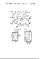
- FIG. 3A is a schematic illustration of a physical embodiment of the negative mud pressure pulse generator of FIGS. 2A and 2B, together with instrumentation and sensor sections in place in a drill string near the drill bit.
- FIG. 3B is a drawing of the negative mud pressure pulse generator of FIGS. 2A and 2B taken in proportional dimensions from an engineering assembly drawing used in actual manufacture of the device.
- FIG. 3C is a schematic diagram of a radioactivity type sensor and associated instrumentation.
- FIG. 3D is a schematic diagram of a temperature type sensor and associated instrumentation.
- FIG. 3E is a schematic diagram of typical instrumentation for controlling actuation of the valve of the negative mud pressure pulse generator.
- FIG. 4 is a schematic illustration showing typical aboveground equipment in accordance with a preferred embodiment of the invention, wherein the downhole parameter being sensed is radioactivity.
- FIG. 5 is a graphic illustration, in idealized form, showing certain wave forms and pulses and time relationships to aid in explanation of the signal extractor portion 102 of FIG. 4.
- FIG. 6 is a schematic block diagram showing component 105 of the signal extractor 102 of FIG. 4 in further detail.
- FIG. 7 is a schematic block diagram showing component 107 of the signal extractor 102 of FIG. 4 in further detail.
- FIG. 8 is a schematic block diagram showing another form of aboveground equipment that may be utilized.
- FIG. 9 is a schematic block diagram showing still another form of aboveground equipment that may be utilized.
- FIG. 10 is a schematic block diagram showing an alternate timing pulse generator that may be utilized.
- FIG. 11 is a schematic block diagram showing still another form of aboveground equipment that may be utilized.
- the mud volume inside the pipe is of the order of 5,000 gallons.
- the bulk elastic modulus for compressed drilling mud is 400,000
- discharging 0.5 gallons of fluid will cause a pressure drop of 40 psi, (if we consider the 5,000 gallons as being in a simple tank). It can be assumed, therefore, that discharging mud near the bottom of such drill pipe at the rate of 0.125 gallons/sec. will cause a signal of 10 psi/sec. at the surface.
- the system of the present invention has a number of important advantages:
- the rapid discharge at a rate of as little as 0.125 gallons/sec will generate a "sharp" pulse, that is a pulse containing a high rate of change of pressure, i.e., a high dp/dt index (e.g. 40).
- a high dp/dt index e.g. 40
- the rapid opening of the bypass valve will also minimize wear for the following reasons: When the bypass valve is closed, there obviously is no wear on the valve seat. When the valve is open (and the valve area is large compared to a restriction or restrictions following it), the valve will be exposed to low velocity fluid and, consequently, the wear will be mostly in the following restriction or restrictions which can be made expendable and of very non-errodable material such as boron carbide.
- Changing the orifice size can determine the flow rate in gallons per second. It was determined that flows larger than about 0.3 gallons per second produced little improvement in the signal. In comparing the signals from a depth of 5,012 feet, three different orifice sizes were tested, 0.509" diameter, 0.427" diameter and 0.268" diameter. It was determined that the 0.268" diameter orifice generated a signal at the surface nearly as intense as the one generated by the 0.509" diameter orifice.
- FIG. 1 there is schematically illustrated a typical drilling rig 10 including a mud circulating pump 12 connected to a discharge pipe 14, a standpipe 16, a high pressure flexible rotary hose 18, a swivel 20 and a drilling string 22, comprising the usual drill pipe and drill collars, and a jet type bit 26.
- the negative mud pressure pulse generator 28 is of a special design. It generates a series of programmed pulses and, each pulse consists of a short momentary reduction in mud pressure. In one embodiment, this is accomplished by means including a valve that momentarily opens a passageway between the inside and the outside of the drill collar 24, i.e., the valve controls a passageway between the inside of the drill collar 24 and the annulus 29 formed by the outside of the drill collar and the well bore.
- Aboveground equipment generally designated as 32, is connected to a pressure transducer 100, which in turn is connected to standpipe 16.
- the transducer 100 could be connected into the stationary portion of swivel 20, if desired.
- FIGS. 2A and 2B show the negative mud pressure pulse generator 28 in diagramatic form to facilitate explanation of its function and manner of operation.
- the negative mud pressure pulse generator comprises a valve inlet chamber 42, a valve outlet chamber 44, and a compensator chamber 72.
- the valve inlet chamber 42 is hydraulically connected via an inlet passageway 38 to the inside of the drill collar 24.
- the valve inlet chamber 42 is also hydraulically connected via a passageway 48 to the valve outlet chamber 44. Hydraulic flow through passageway 48 is controlled by the cooperation of a valve 36 with its seat 37.
- the valve outlet chamber 44 is hydraulically connected via an outlet passageway 51 to the annulus 29. Interposed in the outlet passageway 51 are first and second compensator orifices 52, 53.
- the chamber 40 between the orifices 52, 53 is hydraulically connected via a conduit 74 to the compensator chamber 72.
- the inlet chamber 42 communicates with compensator chamber 72 via a cylinder 49, which receives a compensating piston 50 that is connected to the valve 36 by means of a shaft 46.
- the valve 36 is also connected, by means of a shaft 47 (see FIGS. 3A and 3B) to an actuator device 54.
- FIG. 2B shows the valve 36 of the negative mud pressure pulse generator 28 in the "closed” condition.
- the striated part indicates “high” pressure and the blank part indicates “low” pressure.
- Pressure magnitudes, such as “high”, “low” and “intermediate” are relative pressures, i.e., the difference between the pressure at a given location and the annulus pressure which is here considered to be zero; the actual or real pressure would be equal to these magnitudes plus the hydrostatic head, which may be 10,000 psi or higher.
- the effective area of the valve 36 is made somewhat larger than the effective area of the piston 50 on the shaft side and, consequently, when the valve 36 is closed or nearly closed, the force on the shaft 46 is in the direction shown by the arrow in FIG. 2B and may be equal to about 1,000 ⁇ (a-a') where a is the effective area of the valve 36 and a' is the effective area of the compensating piston 50 on the shaft side.
- FIG. 2A shows the valve 36 in the "open" condition, i.e., permitting mud flow from valve inlet chamber 42 to valve outlet chamber 44 and via outlet passageway 51 to the annulus 29.
- the first and second compensator orifices 52 and 53 each provide a predetermined restriction to the mud flow and each causes a pressure drop. Consequently, the pressure inside the chamber 72 can be made to have any value between the maximum pressure inside chamber 44 and the minimum value at the exit of outlet passageway 51 which corresponds to the pressure inside the annulus 29.
- the striated part indicates “high” pressure and the blank part at the exit of outlet passageway 51 is “low” pressure.
- the mud encounters two restrictions to flow: orifice 52 and orifice 53, as a consequence of which, the pressure in the chamber 40 is intermediate between the "high” pressure indicated by the striated section and the "low” pressure at the exit of outlet passageway 51.
- This "intermediate” pressure is indicated by the stippled area in FIG. 2A.
- This "intermediate” pressure is originated in the chamber 40 between orifices 52 and 53 and communicates via conduit 74 to the compensator chamber 72.
- the pressure in this compensator chamber 72 can, consequently, be adjusted to any reasonable value between the "high” pressure in valve outlet chamber 44 and the "low” pressure at the exit of outlet passageway 51.
- the proportioning of the sizes of the orifices 52 and 53 therefore, controls the pressure in compensator chamber 72 and, consequently, the force on compensator piston 50. If the orifice 53 were the same size as orifice 52, then the pressure in chamber 40 (and compensator chamber 72) would be about midway between that of valve outlet chamber 44 and the annulus 29.
- orifice 53 As the size of orifice 53 is made larger than that of orifice 52, the pressure in compensator chamber 72 will be relatively decreased, and as the size of orifice 53 is made smaller than that of orifice 52, the pressure in compensator chamber 72 will be relatively increased. For example, if orifice 53 is made small compared to orifice 52, the pressure in compensator chamber 72 will be high and, therefore, the force on the head of piston 50 will be high and tend to close the valve 36. On the other hand, if orifice 53 is large compared to orifice 52, the pressure in chamber 72 will be low, thus, tending to allow the valve 36 to remain open. It is seen, therefore, that the force on the head of piston 50 can be adjusted between wide limits, thus, providing a means for adjusting the action of the valve 36.
- the force tending to close the valve 36 in FIG. 2B, and the force tending to open the valve 36 in FIG. 2A are determined by first and second independent parameters, i.e., the force tending to close the valve is derived from the effective area differences of the valve 36 and the rod side of compensator piston 50; whereas the force tending to open the valve is derived from the relative sizes of the orifices 52 and 53.
- the valve 36 can be made to open or close by the application of a small external mechanical force.
- valve 36 has a "bi-stable” action, i.e., the valve is “flipped” or “toggled” from the "open” to the “closed” position or vice versa.
- first said independent parameter is chosen so that when the valve is within the region of nearly closed to fully closed, a predominant force of predetermined magnitude in the valve "close” direction is applied and maintained; and the second said independent parameter is chosen so that when the valve is within the region of nearly open to fully open, a predominant force of predetermined magnitude in the valve "open” direction is applied and maintained.
- the negative mud pressure pulse generator 28 of the present invention utilizes existing energy derived from the mud pressure in such a manner so as to greatly reduce the amount of external energy required to operate the valve 36 and, in addition, to impart to the valve 36 a "bi-stable” or “toggle” action.
- FIG. 3A illustrates in schematic form a physical embodiment of the negative mud pressure pulse generator 28 and associated downhole equipment as it would be installed in the drilling apparatus of FIG. 1.
- the reference numerals that are applied in FIGS. 1, 2A and 2B refer to corresponding parts when applied to FIG. 3A.
- a sub 58 which is typically 63/4" O.D. and 3' long, supports an inner housing 56 by means of arms, or perforated or slotted support members (not shown).
- the inner housing 56 contains the negative mud pressure pulse generator 28 and carries at its lower end portion instrumentation sections 62, 66 and sensor section 64.
- the mud from inside the drill collar 24 passes around the housing 56 in the direction of the arrows.
- a filter 60 prevents mud solids from entering the housing.
- the valve 36 is shown to be operated by an actuating device 54. When the valve 36 is open, as shown in FIG. 2A, some mud is bypassed into the annulus 29. The bent arrows show the direction of this bypassed mud. The pressure that forces the mud into the annulus 29 is the pressure across the jets of bit 26. When valve 36 is closed, the bypass to the annulus 29 is closed.
- the floating piston 76 separates chamber 72 from an oil filled chamber 78.
- Actuating device 54 is mounted within an oil filled chamber 80.
- An equalizing passageway 82 connects chamber 78 with chamber 80.
- Passageway 82 is partially shown in dashed lines in FIG. 3A and is not shown in FIG. 3B since it is located in a different plane from the cross section shown.
- Numeral 68 represents a standard drill collar and numeral 69 a box-box sub.
- Section 66 is 23/8' in diameter and fits into a standard 15'63/4" O.D.-31/4" I.D. drill collar.
- the unit 30 is provided with special centralizer arms 70 which fit snugly into box-box sub 69.
- the centralizer arms 70 are designed to centralize the unit 30 while allowing free passage of mud.
- FIG. 3B bears the corresponding reference numerals of FIGS. 2A, 2B and 3A and shows the negative mud pressure pulse generator 28 in sufficient proportion and detail to illustrate to one skilled in the art its actual construction.
- the actuating device 54 comprises a pair of electrical solenoids arranged in opposition.
- the winding 55 of the upper solenoid is disposed to exert a force in the upward direction on its armature 57, while the winding 59 of the lower solenoid is disposed to exert a force in the downward direction on its armature 61.
- the armatures 57, 61 are loosely coupled to a mechanical linkage 63 that is fixed to the shaft 47 so that a "hammer” effect is achieved; i.e., when a solenoid winding is energized, its armature moves a short distance before picking up the load of shaft 47 with a hammer like impact.
- This "hammer” action has a beneficial effect upon the opening and closing operations of the valve 36.
- Suitable solenoids for this application are the Size 6EC, medium stroke, conical face, type manufactured by Ledex, Inc., of Dayton, Ohio.
- the orifices 52, 53 are made to have smaller opening areas than that of the passageway 48, so that the velocity of mud flow over the sealing surfaces of valve 36 and its seat 37 is significantly reduced when compared to the velocity of mud flow through the orifices 52, 53; thus, concentrating wear on the orifices 52, 53, which are made of wear resistant material (such as boron carbide) and which are also made readily replaceable in the "field", as indicated in FIG. 3B.
- valve 36 Because the negative mud pressure pulse generator 28 is exposed to severe vibration forces, the design must provide for stability of the valve 36 in both its open or closed position. The requisite stability is provided by the "hydraulic detent” or “bi-stable” action of the valve 36 which was previously herein described.
- the vertical acceleration encountered in drilling is more severe in the upward than in the downward direction.
- the drill bit and drill collars 24 are forced upwards, i.e., accelerated in the upward direction; but once the drill bit is raised upward and out of contact with the rock, there is little force other than the acceleration due to gravity that forces the drill bit and drill collars downwardly. Consequently, the acceleration upward can be several hundred g's but the acceleration downward is only of the order of 1 g.
- the valve 36 therefore, must be designed so that when in the closed position, high upwards acceleration tends to keep it closed, i.e., makes it seat better, and high downward acceleration (assumed to be small) tends to open the valve. This has been accomplished in the design, as can be seen from FIGS. 3A and 3B.
- the negative mud pressure pulse generator 28 of the present invention provides a very rapid action for the valve 36; i.e., the valve 36 can be made to open (or to close) with the application of the required 350 watts for only about 20 milliseconds.
- the amount of energy required to open (or close) the valve is, therefore, ##EQU1##
- the valve Assuming that the valve is operated once every four seconds, a single battery charge is able to operate the valve continuously for over one month. It is an important requirement in logging while drilling that the downhole apparatus be capable of operation unattended (i.e., without battery recharge) for at lease the length of time between "round trips", i.e., the time that a single bit can drill without replacement, the best bits last only about 100-300 hours and, therefore, the 30 day figure above is more than adequate.
- Drilling mud usually contains not only colloidal particles in suspension but also larger grains of sand and other particles.
- orifice 52 0.500" in diameter
- orifice 53 0.306" in diameter
- stroke of valve 36 0.125"
- diameter of piston 50 0.383"
- diameter of valve 36 at its seating surface 0.430"
- angle of seat 37 relative to axis of valve movement 60°
- diameter of opening at seat 37 or passageway 48 0.375"
- diameter of valve shaft 46, 47, 0.187 the following dimensions may be considered as typical: orifice 52, 0.500" in diameter; orifice 53, 0.306" in diameter; stroke of valve 36, 0.125"; diameter of piston 50, 0.383"; diameter of valve 36 at its seating surface, 0.430”; angle of seat 37 relative to axis of valve movement, 60°; diameter of opening at seat 37 or passageway 48, 0.375"; diameter of valve shaft 46, 47, 0.187".
- FIG. 3C illustrates a natural gamma ray sensor and its associated circuitry which in this example is of the analog type.
- FIG. 3D illustrates a temperature sensor which in this example is of the digital type. Either one of these sensors can be connected to the input terminal of the instrumentation illustrated by FIG. 3E which will be hereinafter described.
- a geiger counter 168 is provided with the conventional high voltage supply +HV.
- the geiger counter 168 generates pulses and is connected through a capacitor 169 to amplifier 171 which generates pulses at its output that correspond to those of the geiger counter 168.
- a scale of 1024 circuit 172 generates one output pulse for each 1024 geiger counter pulses and its output is shown as pulses having a separation t 1 .
- FIG. 3D illustrates the case of the temperature sensor.
- the temperature is sensed by a thermistor 173, i.e., a semiconductor that varies in resistance with temperature (it is provided with a suitable power supply, not shown) and it is assumed that the output of the thermister 173 is a DC voltage proportioned to temperature.
- the amplifier 174 amplifies this DC voltage and impresses it on an analog-to-digital convertor 175 which in turn generates a series of binary bytes, one after the other, each representative of a number proportional to the sensed temperature.
- the outputs of the power amplifiers 185, 186 are utilized to control energization of the windings of the "back-to-back" coupled solenoids (hereinabove described) to actuate the valve 36.
- winding 55 When winding 55 is energized the solenoid armature 57 (see FIG. 3B) is moved upwardly, pushing upwardly on shaft 47 to actuate valve 36 to the "open” position.
- winding 59 is energized, the solenoid armature 61 is moved downwardly, pulling downward on the shaft 47 to actuate the valve 36 to the "close” position.
- the magnitude of the downhole parameter is represented by electric pulses.
- the sequence of the pulses represents a code (binary or other) and this sequence represents the magnitude of the parameter.
- FIG. 3E illustrates how each single pulse of this code is processed to operate the valve 36.
- numeral 177 represents one such pulse which is narrow in time; being only a few microseconds long. This pulse 177 is impressed upon the circuitry contained in block 178.
- This block 178 contains a so called “one shot” univibrator and suitable inverting rectifying circuits well known in the electronics art and provides (in response to the single input pulse) two output pulses separated in time by t 1 (the first pulse is normally time coincident with the input pulse and the second appears later by an amount of time equal to t 1 ) as shown by pulses 179 and 180.
- These electric pulses 179, 180 are now impressed, respectively, upon the circuitry contained in blocks 181, 182.
- These two circuits are identical and are so called pulse lengthening circuits, also well known in the electronics art.
- Each input pulse is lengthened to provide output pulses 183 and 184.
- These pulses are respectively applied to the "Darlington" power amplifiers 185 and 186 (as manufactured by Lambda Mfg. Co. of Melville, N.Y., and sold under the type PMD16K100).
- the Darlington 185 is turned on for 20 milliseconds and then turned off. Then 500 milliseconds later the Darlington 186 is turned on for 20 milliseconds and then turned off.
- the valve 36 is opened for 500 milliseconds without requiring any energy during this period. Energy is required only during the short 20 millisecond periods that are required to actuate the valve 36 to the "open" or to the "close” position.
- the figures given above are for illustrative purposes only.
- valve 36 by making the action of the valve 36: (a) very fast and (b) bi-stable; very high pressures and volumes of mud can be valved without the necessity of employing large amounts of energy and as hereinabove described, relatively small energy batteries can operate the valve about one million times.
- the weight of the entire valve mechanism 36 of FIGS. 2A or 3A, including the solenoid armature 54, shaft 46 and piston 50 is approximately 9 ounces.
- the valve 36 has been designed to operate at a differential pressure of 1,600 psi and proportioned to operate at optimum performance, including the consequence that the force required to open and shut the valve 36 must exceed the force due to vertical acceleration of all the apparatus near the bit 26.
- FIG. 4 shows typical above ground equipment in accordance with a preferred embodiment of the invention, wherein the downhole parameter being sensed is the radioactivity of formations traversed by the bore while drilling is in progress.
- the corresponding portion of the logging equipment which is below the earth's surface has been previously described and shown in FIGS. 2A, 2B, and 3A-G.
- pressure transducer 100 connected to the standpipe 16 converts the variation of mud pressure within the standpipe into a varying electrical voltage.
- This voltage represents a mixture of two component signals: the useful, information carrying signal and the interferring signal.
- the information carrying signal is a succession of short, negative mud pressure pulses produced by the sudden opening and closing of the valve 36.
- the interferring signal is in the form of relatively slow and periodic pressure variations which are generated by the strokes of the mud pump 12. These mud pump signals tend to mask or obscure the information one desires to obtain by utilizing the short negative mud pressure pulses.
- One of the objectives of this invention is to recover, from the "contaminated" signal produced by the transducer, a "clean" signal which gives the desired information. This is accomplished by means of a signal extractor 102 which is applied to the output terminal 101 of the pressure transducer 100.
- the signal extractor eliminates the interferring effects and produces across its output terminal 108 a succession of pulses from which the information regarding the downhole parameter can be readily obtained.
- the signal extractor 102 is controlled in a predetermined manner by a succession of timing pulses obtained from a pulse generator 111 and applied to the control terminals 113, 114.
- the pulse generator 111 is mechanically driven by the mud pump 12 to produce an appropriate number of timing pulses per revolution of the pump.
- a chain drive transmission assembly 112 is provided for this purpose.
- the "clean" information carrying signal obtained from the extractor 102 is in the form of pulses derived from the actuation of valve 36 of generator 28.
- the relevant information is provided by the time intervals separating the pulses.
- a time-to-amplitude convertor 115 connected to the signal extractor output terminal 108 converts these pulses derived from the actuation of the valve 36 of generator 28 into signals having magnitudes representing the intervals therebetween.
- the convertor 115 is a well known electronic device and can be made up of components manufactured by the Burr-Brown company of Tuscon, Ariz., U.S.A.
- time-to-amplitude converters see: M. Bertolaccini and S. Cova, "Logic Design of High Precision Time to Pulse Height Converters", Nuclear Instruments and Methods 121 (1974), pp. 547-566, North Holland Publishing Co.
- the signals derived from the convertor 115 are in turn applied to the input terminal 109 of a reciprocation circuit 118.
- the reciprocation circuit 118 (as, for example, manufactured by Analog Devices, Inc. of Norwood, Mass.) produces output voltages which are the reciprocals of the input voltages. Thus, if a voltage of magnitude M is applied to reciprocation circuit 118, an output voltage having magnitude 1/M is obtained.
- These signals having magnitudes 1/M are in turn recorded on the chart of a recorder 120.
- the record chart of recorder 120 is moved in correlation with changing depth of the sensor unit 30 by a depth sensing device 121.
- the depth sensing device may be, for example, a modification or adaptation of equipment such as marketed by The Geolograph Medeavis Company of Oklahoma City, Okla., U.S.A.
- S(t) is the useful information carrying signal formed by the negative mud pressure pulses P 1 , P 2 , and P 3 aligned along the time axis t. [See FIG. 5 (axis A)].
- the times of arrival of these pulses which correspond to the times of actuation of the valve 36 of generator 28, are t 1 , t 2 and t 3 , respectively.
- the interfering signal produced by the mud pump 12 is represented in FIG. 5 (axis A) by a periodic but not necessarily sinusodal function N(t) having a period T. The length of the period is related to the speed of rotation of the pump.
- Axes A-E in FIG. 5 are positioned one below the other so that one can compare the signals in their time relationships one to another. Using these figures, we can now enumerate the instrumental steps which are involved in the operation of the signal extractor 102. These are as follows:
- S(t-T) and N(t-T) are, respectively, the displaced useful signal and displaced interfering signal. Both signals are shown in FIG. 5 (axis B).
- the signal S(t-T) is represented by pulses P 1 .sup.(a), P 2 .sup.(a) and P 3 .sup.(a) which have been obtained by displacing by an amount T the corresponding pulses P 1 , P 2 and P 3 in FIG. 5 (axis A).
- the signal N(t-T) in FIG. 5 (axis B) is shown to be in exact synchronism with N(t) in FIG. 5 (axis A). This is due to the periodicity of the signal.
- M(t) consists of impulses which occur in pairs. Each pair contains a negative and a positive pulse separated one from another by a time interval T.
- T time interval
- P 1 .sup.(d) coincides with P 1 .sup.(b) and P 1 .sup.(c)
- P 2 .sup.(d) coincides with P 2 .sup.(b) and P 2 .sup.(c)
- P 3 .sup.(d) coincides with P 3 .sup.(b) and P 3 .sup.(c)
- the times at which the pulses P 1 .sup.(d), P 2 .sup.(d) and P 3 .sup.(d) occur are t 1 +T, t 2 +T and t 3 +T.
- the pulses P 1 .sup.(d), P 2 .sup.(d) and P 3 .sup.(d) correspond to the pulses P 1 , P 2 and P 3 shown in FIG. 5 (axis A). Consequently, the pulses in FIG. 5 (axis E) also represent this useful function which now is S(t-T) since it has only been displaced by T. It is evident that the pulses in FIG. 5 (axis E) provide the information which we are seeking to obtain.
- the time interval between P 1 .sup.(d) and P 2 .sup.(d) is ⁇ 1
- the time interval between P 2 .sup.(d) and P 3 .sup.(d) is ⁇ 2 , etc.
- the quantities ⁇ 1 , ⁇ 2 , etc. are indicative of the radiation measured by the gamma ray detector.
- the component 105 receives at its input terminal 101 (which is the same as that of the signal extractor 102 of FIG. 4) the signal F(t). As shown in FIG. 6, this signal is transmitted through an amplifier 130 to the input terminal 131 of a delay network 132. The delay network delays F(t) by T, thus, producing at its output terminal 134 the signal F(t-T).
- This signal is a sum of two component signals S(t-T) and N(t-T) which are shown in FIG. 5 (axis B).
- the signal F(t-T) is applied to one input terminal 134 of a subtractor 135.
- the other input terminal 136 of the subtractor receives directly the signal F(t), which is transmitted from terminal 101 by means of conductor 137.
- the delay network 132 is provided with control terminal 113 which receives a signal controlling the delay T. It is important that the length of the delay T be the same as the period of mud pressure oscillations produced by the mud pump 12.
- the amount of the delay T is controlled by the timing impulses derived from pulse generator 111 shown also in FIG. 4 and applied via conductor 110 to the control terminal 113. It is noted that the delay T is the same as the period of oscillation of mud pressure produced in the successive strokes of the mud pump 12. Consequently, the frequency of these timing pulses must be controlled by the rotation of the pump.
- N 1 strokes per second.
- T 1/N 1 .
- the pulse generator 111 produces timing pulses at a relatively high rate N 2 , which is a multiple of N 1 .
- N 2 KN 1 , where K is a constant which has been chosen to be 512.
- K is a constant which has been chosen to be 512.
- the rate of pulsation of the mud pump 12 varies with time and, accordingly, N 2 will vary so as to insure that the delay produced by delay network 132 will always be equal to one period of the mud pressure oscillations produced by the mud pump 12.
- the delay network 132 which is controlled, as described above, may be a Reticon Model SAD-1024 Dual Analog Delay Line as marketed by Reticon Corporation, Sunnyvale, Calif., U.S.A.
- the instrumental steps herebefore described are the steps 1 and 2 performed by the component 105 of the signal extractor 102.
- the signal M(t) is now applied through conductor 140 to a delay network 141.
- This delay network is identical to that designated as 132 in FIG. 6. It receives, at its control terminal 114, the same control signal which was applied to the control terminal 113 of the delay network 105. Consequently, the amount of delay produced by delay network 141 is T and the signal appearing at the output of 141 is M(t-T) as shown in FIG. 5 (axis D).
- This output signal is transmitted through an amplifier 143 to one input terminal 145 of an AND gate 146.
- the undelayed signal M(t) is applied through the conductor 147 and amplifier 148 to the other input terminal 149 of the AND gate 146.
- pulses are transmitted to the time-to-amplitude convertor 115 to produce at the output of the time-to-amplitude convertor 115 signals of various magnitude such as ⁇ 1 , ⁇ 2 , ⁇ 3 , etc., that represent time intervals between the arrival of pulses.
- signals are in turn fed to and transformed by the reciprocation circuit 118 of FIG. 4 into other reciprocal signals having magnitudes 1/ ⁇ 1 , 1/ ⁇ 2 , 1/ ⁇ 3 , respectively.
- These reciprocal signals are recorded by recorder 120 of FIG. 4. It is apparent that the quantities 1/ ⁇ 1 , 1/ ⁇ 2 and 1/ ⁇ 3 represent the intensity of radioactivity of formations sensed by the sensor unit 30 at various depths in the borehole.
- FIG. 8 the output of the pressure transducer 100 is fed to an analog-to-digital convertor 103, the output of which is fed to a digital computer 104.
- the operations indicated in FIG. 8 are performed by the elements designated 122, 123, 124, 125 and 126 in the digital computer 104.
- Timing signals from a pulse generator 111 or 140 are introduced to the digital computer 104 in order to control the delays in accordance with the pump speed.
- the operations indicated in the dotted rectangle of FIG. 8 are performed mathematically in a sequence which may be flow charted.
- the output of the computer 104 is fed to a digital-to-analog converter 127, the output of which is fed to the recorder 120.
- FIG. 9 there is shown an arrangement similar in some respects to that of FIG. 4, but wherein the data to be obtained and recorded are the temperature at the location of sensor unit 30 of FIG. 1.
- these data, as presented to the signal extractor 102 are in digital form (see FIG. 3D).
- the signal extractor 102 of FIG. 9 is identical to that of FIG. 4, but the time-to-amplitude convertor 115 and the reciprocation circuit 118 of FIG. 4 are replaced by a digital-to-analog convertor 141.
- the output signals of an appropriate pulse generator will be applied to the control terminal 110 of the signal extractor 102.
- FIG. 10 illustrates such an alternate means.
- the signal extractor 102 of FIG. 4 is provided at its terminal 110 with pulses at a rate of 512 pulses per full pump stroke. It must be clearly understood that this rate must be rigorously sychronized with the pump strokes. All the "times" shown as T, t 1 , t 2 , etc. in FIG. 5 are not so-called “real time”, but are directly related to the speed of the mud pump 12 and rigorously, T, t 1 , t 2 , etc.
- component 145 is a VCO or "voltage controlled oscillator" which at its output 110 produces electric pulses the frequency of which is controlled by the DC voltage applied at its input terminal 108.
- Component 150 is a binary divider or scaler that divides the frequency of the pulses impressed on its input terminal 116 and generates output pulses at its output terminal 117 having a frequency equal to 1/512th of frequency of the input pulses.
- Component 119 is a phase comparator that compares two inputs (one from scaler output terminal 117 and one from the output terminal 130 of pressure transducer 100), and provides at its output terminal 128 a voltage which is zero volts DC when the two inputs 117 and 130 are exactly equal in phase; and provides a positive voltage when the input at 117 leads the input at 130 in phase; and a negative DC voltage when the input at 117 lags the input at 130 in phase.
- a battery 129 is provided to properly bias the VCO 145.
- the circuit 151, just described, is known as "phase locked loop". The operation is best explained by an example: Assume that the pump pulse frequency (pump stroke frequency) is 1 Hz and the VCO is generating 512 Hz.
- the output of the scaler 150 will then generate exactly 1 Hz.
- the 1 Hz from the scaler 150 and the 1 Hz from the pressure transducer 100 will then be exactly matched in frequency and phase and the output of the comparator at terminal 128 will be zero volts, and the VCO 145, when properly biased by battery 129, will generate exactly 512 pulses per stroke.
- the frequency at terminal 130 will than be somewhat greater than 1 Hz--i.e., 1+ ⁇ 1 Hz.
- the frequency at terminal 110 will always accurately follow the frequency of the mud pump 12 and will always be its 512th multiple.
- FIG. 11 A third arrangement that may be used for obtaining such timing pulses is illustrated by FIG. 11 and is based on "auto-correlation".
- the input terminal 154 of a correlator 152 is supplied by the output of the pressure transducer 100, and receives the function F(t) which contains the periodic signal N(t) and the function S(t) which may be considered a random function.
- the output of the pressure transducer 100 is also applied to the input terminal 101 of the signal extractor 102.
- the correlator 152 is adapted to produce across its output terminals the autocorrelation function of F(t) which is ##EQU2## Where the bar in the above expression indicates averaging over an appropriate period of time.
- the function ⁇ ff ( ⁇ ) can be expressed as ##EQU3##
- ⁇ nn ( ⁇ ) is periodic
- ⁇ ff ( ⁇ ) is also periodic and it has the period ⁇ .
- This function which is obtained in the output of the correlator 152 is in turn applied to a pulse multiplier 153 which produces a succession of timing pulses similar to those produced by the pulse generator 111 in FIG. 4 and which are applied to input terminal 110 of the signal extractor 102.
- the pulse multiplier 153 multiplies the frequency of the input pulses by a phase locked loop system similar to that of FIG. 10 or by any other conventional means.
- the remaining elements in FIG. 11 are the same as those in FIG. 4, except, of course, that the pulse generator 111 and its chain drive transmission assembly 112 are eliminated.
- the correllator 152 of FIG. 11 may be Model 3721A manufactured by Hewlett Packard Company of Palo Alto, Calif.
- the correllator 152 could also be one of the types described in the following references: A. E. Hastings and J. E. Meade "A Device for Computing Correlation Functions", Review of Scientific Instruments, Vol. 23, 1952, pp. 347-349; and F. E. Brooks, Jr. and H. W. Smith, "A Computer for Correlation Functions", Review of Scientific Instruments, Vol. 23, 1952, pp. 121-126.
- sensors for only two downhole parameters it is, however, to be understood that sensors for various other downhole parameters could be used as well. It is also to be understood that sensors for a plurality of downhole parameters may be used at the same time, in which case, conventional techniques would be employed (such as time sharing, multiplexing, or the like) to handle the data representing the plurality of parameters.
- a turbine or "mud motor” such as a Dynadrill, manufactured by Smith Industries, Inc., Houston, Tex.
- the drill string 31 of FIG. 1 is not rotated by the rotary table at the surface.
- the rotating action to turn the bit 26 is derived from such a mud motor, which usually is located immediately above the bit 26 in the drill string comprising elements 22, 24, 28, 30, of FIG. 1.
- a large pressure drop occurs across it (since the mud motor derives its power from the mud flow). This large pressure drop can be utilized to supply the pressure difference between the inside of the drill string and the annulus and, in such case, a "jet" type bit need not be employed.
- flow restriction means for purposes herein, applies to either a jet type bit, or a mud motor, or both.
- high pressure zone applies to the drilling fluid pressure on the upstream side of the "flow restriction means” and the term “low pressure zone” applies to the drilling fluid pressure on the downstream side of the "flow restriction means”.
- a plurality of mud pumps are employed on a single drilling rig and these pumps are not necessarily operated in synchronism.
- the periodic pressure curve of FIG. 5A would, in the practical case, not be a simple periodic function as shown by N(t) but would be the sum of three components, each component being periodic and having its own distinct period.
- each periodic component of the interfering mud pulse pressure signal can be separately nullified. Suitable interconnection will then produce a signal from which the interfering mud pump pressure signals are eliminated.
Abstract
Description
F(t)=S(t)+N(t) (1)
F(t-T)=S(t-T)+N(t-T) (2)
N(t-T)≡N(t) (3)
M(t)=F(t)-F(t-T) (4)
M(t)=S(t)-S(t-T) (5)
φ.sub.ff (τ)=φ.sub.nn (τ) (10)
Claims (4)
Priority Applications (1)
| Application Number | Priority Date | Filing Date | Title |
|---|---|---|---|
| US06/389,247 US4553226A (en) | 1980-01-10 | 1982-06-17 | Systems, apparatus and methods for measuring while drilling |
Applications Claiming Priority (2)
| Application Number | Priority Date | Filing Date | Title |
|---|---|---|---|
| US06/110,848 US4351037A (en) | 1977-12-05 | 1980-01-10 | Systems, apparatus and methods for measuring while drilling |
| US06/389,247 US4553226A (en) | 1980-01-10 | 1982-06-17 | Systems, apparatus and methods for measuring while drilling |
Related Parent Applications (1)
| Application Number | Title | Priority Date | Filing Date |
|---|---|---|---|
| US06/110,848 Continuation US4351037A (en) | 1977-12-05 | 1980-01-10 | Systems, apparatus and methods for measuring while drilling |
Publications (1)
| Publication Number | Publication Date |
|---|---|
| US4553226A true US4553226A (en) | 1985-11-12 |
Family
ID=26808437
Family Applications (1)
| Application Number | Title | Priority Date | Filing Date |
|---|---|---|---|
| US06/389,247 Expired - Lifetime US4553226A (en) | 1980-01-10 | 1982-06-17 | Systems, apparatus and methods for measuring while drilling |
Country Status (1)
| Country | Link |
|---|---|
| US (1) | US4553226A (en) |
Cited By (42)
| Publication number | Priority date | Publication date | Assignee | Title |
|---|---|---|---|---|
| US4694439A (en) * | 1985-07-18 | 1987-09-15 | Scientific Drilling International | Well information telemetry by variation of mud flow rate |
| US4703461A (en) * | 1986-03-31 | 1987-10-27 | Eastman Christensen Co. | Universal mud pulse telemetry system |
| US4774694A (en) * | 1981-12-15 | 1988-09-27 | Scientific Drilling International | Well information telemetry by variation of mud flow rate |
| US4821035A (en) * | 1984-05-01 | 1989-04-11 | Comdisco Resources, Inc. | Method and apparatus using a well casing for transmitting data up a well |
| US4845494A (en) * | 1984-05-01 | 1989-07-04 | Comdisco Resources, Inc. | Method and apparatus using casing and tubing for transmitting data up a well |
| US5160925A (en) * | 1991-04-17 | 1992-11-03 | Smith International, Inc. | Short hop communication link for downhole mwd system |
| US5390153A (en) * | 1977-12-05 | 1995-02-14 | Scherbatskoy; Serge A. | Measuring while drilling employing cascaded transmission systems |
| US5414673A (en) * | 1992-04-21 | 1995-05-09 | Scherbatskoy; Serge A. | Sonic measurement while drilling |
| US5473579A (en) * | 1993-10-25 | 1995-12-05 | Ronald L. Shaw | Well bore communication pulser |
| US5558153A (en) * | 1994-10-20 | 1996-09-24 | Baker Hughes Incorporated | Method & apparatus for actuating a downhole tool |
| US5806612A (en) * | 1996-02-28 | 1998-09-15 | Dmt-Gesellschaft Fur Forschung Und Prufung Mbh | Apparatus for the transmission of information in a drill string |
| US5983089A (en) * | 1994-09-26 | 1999-11-09 | Endgate Corporation | Slotline-mounted flip chip |
| US6016288A (en) * | 1994-12-05 | 2000-01-18 | Thomas Tools, Inc. | Servo-driven mud pulser |
| US20030209364A1 (en) * | 2002-05-13 | 2003-11-13 | Fadhel Rezgui | Method and device for determining the nature of a formation at the head of drilling tool |
| WO2009134578A2 (en) * | 2008-05-01 | 2009-11-05 | Schlumberger Canada Limited | Drilling system with drill string valves |
| US7658196B2 (en) | 2005-02-24 | 2010-02-09 | Ethicon Endo-Surgery, Inc. | System and method for determining implanted device orientation |
| US7775215B2 (en) | 2005-02-24 | 2010-08-17 | Ethicon Endo-Surgery, Inc. | System and method for determining implanted device positioning and obtaining pressure data |
| US7775966B2 (en) | 2005-02-24 | 2010-08-17 | Ethicon Endo-Surgery, Inc. | Non-invasive pressure measurement in a fluid adjustable restrictive device |
| US7844342B2 (en) | 2008-02-07 | 2010-11-30 | Ethicon Endo-Surgery, Inc. | Powering implantable restriction systems using light |
| US7927270B2 (en) | 2005-02-24 | 2011-04-19 | Ethicon Endo-Surgery, Inc. | External mechanical pressure sensor for gastric band pressure measurements |
| US8016744B2 (en) | 2005-02-24 | 2011-09-13 | Ethicon Endo-Surgery, Inc. | External pressure-based gastric band adjustment system and method |
| US8016745B2 (en) | 2005-02-24 | 2011-09-13 | Ethicon Endo-Surgery, Inc. | Monitoring of a food intake restriction device |
| US8034065B2 (en) | 2008-02-26 | 2011-10-11 | Ethicon Endo-Surgery, Inc. | Controlling pressure in adjustable restriction devices |
| US8057492B2 (en) | 2008-02-12 | 2011-11-15 | Ethicon Endo-Surgery, Inc. | Automatically adjusting band system with MEMS pump |
| US8066629B2 (en) | 2005-02-24 | 2011-11-29 | Ethicon Endo-Surgery, Inc. | Apparatus for adjustment and sensing of gastric band pressure |
| US8100870B2 (en) | 2007-12-14 | 2012-01-24 | Ethicon Endo-Surgery, Inc. | Adjustable height gastric restriction devices and methods |
| US8114345B2 (en) | 2008-02-08 | 2012-02-14 | Ethicon Endo-Surgery, Inc. | System and method of sterilizing an implantable medical device |
| US8142452B2 (en) | 2007-12-27 | 2012-03-27 | Ethicon Endo-Surgery, Inc. | Controlling pressure in adjustable restriction devices |
| US8152710B2 (en) | 2006-04-06 | 2012-04-10 | Ethicon Endo-Surgery, Inc. | Physiological parameter analysis for an implantable restriction device and a data logger |
| US8187162B2 (en) | 2008-03-06 | 2012-05-29 | Ethicon Endo-Surgery, Inc. | Reorientation port |
| US8187163B2 (en) | 2007-12-10 | 2012-05-29 | Ethicon Endo-Surgery, Inc. | Methods for implanting a gastric restriction device |
| US8192350B2 (en) | 2008-01-28 | 2012-06-05 | Ethicon Endo-Surgery, Inc. | Methods and devices for measuring impedance in a gastric restriction system |
| US8221439B2 (en) | 2008-02-07 | 2012-07-17 | Ethicon Endo-Surgery, Inc. | Powering implantable restriction systems using kinetic motion |
| US8233995B2 (en) | 2008-03-06 | 2012-07-31 | Ethicon Endo-Surgery, Inc. | System and method of aligning an implantable antenna |
| US8337389B2 (en) | 2008-01-28 | 2012-12-25 | Ethicon Endo-Surgery, Inc. | Methods and devices for diagnosing performance of a gastric restriction system |
| US8377079B2 (en) | 2007-12-27 | 2013-02-19 | Ethicon Endo-Surgery, Inc. | Constant force mechanisms for regulating restriction devices |
| US8591395B2 (en) | 2008-01-28 | 2013-11-26 | Ethicon Endo-Surgery, Inc. | Gastric restriction device data handling devices and methods |
| US8591532B2 (en) | 2008-02-12 | 2013-11-26 | Ethicon Endo-Sugery, Inc. | Automatically adjusting band system |
| US8870742B2 (en) | 2006-04-06 | 2014-10-28 | Ethicon Endo-Surgery, Inc. | GUI for an implantable restriction device and a data logger |
| CN107339095A (en) * | 2016-12-15 | 2017-11-10 | 天津同创达科石油科技有限公司 | Automatic depth survey system based on pneumatic rotary clasping device |
| US9828853B2 (en) | 2012-09-12 | 2017-11-28 | Halliburton Energy Services, Inc. | Apparatus and method for drilling fluid telemetry |
| US20200072046A1 (en) * | 2016-12-12 | 2020-03-05 | Tracto-Technik Gmbh & Co. Kg | Method and system for determining a soil class and use during determination of a soil class |
Citations (4)
| Publication number | Priority date | Publication date | Assignee | Title |
|---|---|---|---|---|
| US2380520A (en) * | 1942-04-24 | 1945-07-31 | Shell Dev | Borehole indicating apparatus |
| US2925251A (en) * | 1954-03-05 | 1960-02-16 | Jan J Arps | Earth well borehole drilling and logging system |
| US3711825A (en) * | 1970-07-30 | 1973-01-16 | Schlumberger Technology Corp | Data-signaling apparatus for well drilling tools |
| US3736558A (en) * | 1970-07-30 | 1973-05-29 | Schlumberger Technology Corp | Data-signaling apparatus for well drilling tools |
-
1982
- 1982-06-17 US US06/389,247 patent/US4553226A/en not_active Expired - Lifetime
Patent Citations (4)
| Publication number | Priority date | Publication date | Assignee | Title |
|---|---|---|---|---|
| US2380520A (en) * | 1942-04-24 | 1945-07-31 | Shell Dev | Borehole indicating apparatus |
| US2925251A (en) * | 1954-03-05 | 1960-02-16 | Jan J Arps | Earth well borehole drilling and logging system |
| US3711825A (en) * | 1970-07-30 | 1973-01-16 | Schlumberger Technology Corp | Data-signaling apparatus for well drilling tools |
| US3736558A (en) * | 1970-07-30 | 1973-05-29 | Schlumberger Technology Corp | Data-signaling apparatus for well drilling tools |
Cited By (47)
| Publication number | Priority date | Publication date | Assignee | Title |
|---|---|---|---|---|
| US5390153A (en) * | 1977-12-05 | 1995-02-14 | Scherbatskoy; Serge A. | Measuring while drilling employing cascaded transmission systems |
| US4774694A (en) * | 1981-12-15 | 1988-09-27 | Scientific Drilling International | Well information telemetry by variation of mud flow rate |
| US4821035A (en) * | 1984-05-01 | 1989-04-11 | Comdisco Resources, Inc. | Method and apparatus using a well casing for transmitting data up a well |
| US4845494A (en) * | 1984-05-01 | 1989-07-04 | Comdisco Resources, Inc. | Method and apparatus using casing and tubing for transmitting data up a well |
| US4694439A (en) * | 1985-07-18 | 1987-09-15 | Scientific Drilling International | Well information telemetry by variation of mud flow rate |
| US4703461A (en) * | 1986-03-31 | 1987-10-27 | Eastman Christensen Co. | Universal mud pulse telemetry system |
| US5160925A (en) * | 1991-04-17 | 1992-11-03 | Smith International, Inc. | Short hop communication link for downhole mwd system |
| DE4291022B4 (en) * | 1991-04-17 | 2007-06-14 | Halliburton Co., Duncan | Short distance transmission connection for a deep MWD system |
| US5414673A (en) * | 1992-04-21 | 1995-05-09 | Scherbatskoy; Serge A. | Sonic measurement while drilling |
| US5473579A (en) * | 1993-10-25 | 1995-12-05 | Ronald L. Shaw | Well bore communication pulser |
| US5983089A (en) * | 1994-09-26 | 1999-11-09 | Endgate Corporation | Slotline-mounted flip chip |
| US5558153A (en) * | 1994-10-20 | 1996-09-24 | Baker Hughes Incorporated | Method & apparatus for actuating a downhole tool |
| US6016288A (en) * | 1994-12-05 | 2000-01-18 | Thomas Tools, Inc. | Servo-driven mud pulser |
| US5806612A (en) * | 1996-02-28 | 1998-09-15 | Dmt-Gesellschaft Fur Forschung Und Prufung Mbh | Apparatus for the transmission of information in a drill string |
| US20030209364A1 (en) * | 2002-05-13 | 2003-11-13 | Fadhel Rezgui | Method and device for determining the nature of a formation at the head of drilling tool |
| US7927270B2 (en) | 2005-02-24 | 2011-04-19 | Ethicon Endo-Surgery, Inc. | External mechanical pressure sensor for gastric band pressure measurements |
| US8066629B2 (en) | 2005-02-24 | 2011-11-29 | Ethicon Endo-Surgery, Inc. | Apparatus for adjustment and sensing of gastric band pressure |
| US7658196B2 (en) | 2005-02-24 | 2010-02-09 | Ethicon Endo-Surgery, Inc. | System and method for determining implanted device orientation |
| US7775215B2 (en) | 2005-02-24 | 2010-08-17 | Ethicon Endo-Surgery, Inc. | System and method for determining implanted device positioning and obtaining pressure data |
| US7775966B2 (en) | 2005-02-24 | 2010-08-17 | Ethicon Endo-Surgery, Inc. | Non-invasive pressure measurement in a fluid adjustable restrictive device |
| US8016744B2 (en) | 2005-02-24 | 2011-09-13 | Ethicon Endo-Surgery, Inc. | External pressure-based gastric band adjustment system and method |
| US8016745B2 (en) | 2005-02-24 | 2011-09-13 | Ethicon Endo-Surgery, Inc. | Monitoring of a food intake restriction device |
| US8870742B2 (en) | 2006-04-06 | 2014-10-28 | Ethicon Endo-Surgery, Inc. | GUI for an implantable restriction device and a data logger |
| US8152710B2 (en) | 2006-04-06 | 2012-04-10 | Ethicon Endo-Surgery, Inc. | Physiological parameter analysis for an implantable restriction device and a data logger |
| US8187163B2 (en) | 2007-12-10 | 2012-05-29 | Ethicon Endo-Surgery, Inc. | Methods for implanting a gastric restriction device |
| US8100870B2 (en) | 2007-12-14 | 2012-01-24 | Ethicon Endo-Surgery, Inc. | Adjustable height gastric restriction devices and methods |
| US8142452B2 (en) | 2007-12-27 | 2012-03-27 | Ethicon Endo-Surgery, Inc. | Controlling pressure in adjustable restriction devices |
| US8377079B2 (en) | 2007-12-27 | 2013-02-19 | Ethicon Endo-Surgery, Inc. | Constant force mechanisms for regulating restriction devices |
| US8591395B2 (en) | 2008-01-28 | 2013-11-26 | Ethicon Endo-Surgery, Inc. | Gastric restriction device data handling devices and methods |
| US8192350B2 (en) | 2008-01-28 | 2012-06-05 | Ethicon Endo-Surgery, Inc. | Methods and devices for measuring impedance in a gastric restriction system |
| US8337389B2 (en) | 2008-01-28 | 2012-12-25 | Ethicon Endo-Surgery, Inc. | Methods and devices for diagnosing performance of a gastric restriction system |
| US7844342B2 (en) | 2008-02-07 | 2010-11-30 | Ethicon Endo-Surgery, Inc. | Powering implantable restriction systems using light |
| US8221439B2 (en) | 2008-02-07 | 2012-07-17 | Ethicon Endo-Surgery, Inc. | Powering implantable restriction systems using kinetic motion |
| US8114345B2 (en) | 2008-02-08 | 2012-02-14 | Ethicon Endo-Surgery, Inc. | System and method of sterilizing an implantable medical device |
| US8591532B2 (en) | 2008-02-12 | 2013-11-26 | Ethicon Endo-Sugery, Inc. | Automatically adjusting band system |
| US8057492B2 (en) | 2008-02-12 | 2011-11-15 | Ethicon Endo-Surgery, Inc. | Automatically adjusting band system with MEMS pump |
| US8034065B2 (en) | 2008-02-26 | 2011-10-11 | Ethicon Endo-Surgery, Inc. | Controlling pressure in adjustable restriction devices |
| US8187162B2 (en) | 2008-03-06 | 2012-05-29 | Ethicon Endo-Surgery, Inc. | Reorientation port |
| US8233995B2 (en) | 2008-03-06 | 2012-07-31 | Ethicon Endo-Surgery, Inc. | System and method of aligning an implantable antenna |
| US8307913B2 (en) | 2008-05-01 | 2012-11-13 | Schlumberger Technology Corporation | Drilling system with drill string valves |
| WO2009134578A2 (en) * | 2008-05-01 | 2009-11-05 | Schlumberger Canada Limited | Drilling system with drill string valves |
| US20090272580A1 (en) * | 2008-05-01 | 2009-11-05 | Schlumberger Technology Corporation | Drilling system with drill string valves |
| WO2009134578A3 (en) * | 2008-05-01 | 2010-03-18 | Schlumberger Canada Limited | Drilling system with drill string valves |
| US9828853B2 (en) | 2012-09-12 | 2017-11-28 | Halliburton Energy Services, Inc. | Apparatus and method for drilling fluid telemetry |
| US20200072046A1 (en) * | 2016-12-12 | 2020-03-05 | Tracto-Technik Gmbh & Co. Kg | Method and system for determining a soil class and use during determination of a soil class |
| CN107339095A (en) * | 2016-12-15 | 2017-11-10 | 天津同创达科石油科技有限公司 | Automatic depth survey system based on pneumatic rotary clasping device |
| CN107339095B (en) * | 2016-12-15 | 2020-11-06 | 天津同创达科石油科技有限公司 | Automatic well depth measuring system based on pneumatic spinner |
Similar Documents
| Publication | Publication Date | Title |
|---|---|---|
| US4553226A (en) | Systems, apparatus and methods for measuring while drilling | |
| US4351037A (en) | Systems, apparatus and methods for measuring while drilling | |
| CA1124228A (en) | Systems, apparatus and methods for measuring while drilling | |
| US5113379A (en) | Method and apparatus for communicating between spaced locations in a borehole | |
| US4692911A (en) | Methods and apparatus for reducing interfering effects in measurement while drilling operations | |
| US5390153A (en) | Measuring while drilling employing cascaded transmission systems | |
| US4532614A (en) | Wall bore electrical generator | |
| US5182730A (en) | Method and apparatus for transmitting information in a borehole employing signal discrimination | |
| US5079750A (en) | Method and apparatus for transmitting information in a borehole employing discrimination | |
| US3964556A (en) | Downhole signaling system | |
| US4689775A (en) | Direct radiator system and methods for measuring during drilling operations | |
| EA009114B1 (en) | A method for classifying data measured during drilling operations at a wellbore | |
| US4866680A (en) | Method and apparatus for transmitting information in a borehole employing signal discrimination | |
| US5150333A (en) | Method and apparatus for providing improved pressure pulse characteristics for measuring while drilling | |
| US20110149692A1 (en) | Method of Communication Using Improved Multi-Frequency Hydraulic Oscillator | |
| US20190100965A1 (en) | Down-Hole Vibrational Oscillator | |
| US4839870A (en) | Pressure pulse generator system for measuring while drilling | |
| CA2771344C (en) | Sparker-type wellbore seismic energy source having controllable depth-independent frequency | |
| US7382686B2 (en) | Drilling signalling system | |
| GB2096372A (en) | Logging a borehole while drilling | |
| US20040240320A1 (en) | Seismic energy source for use during wellbore drilling | |
| US6697298B1 (en) | High efficiency acoustic transmitting system and method | |
| GB2096373A (en) | Systems and methods for logging a borehole while drilling | |
| US5414673A (en) | Sonic measurement while drilling | |
| US4520665A (en) | System for detecting a native reservoir fluid in a well bore |
Legal Events
| Date | Code | Title | Description |
|---|---|---|---|
| STCF | Information on status: patent grant |
Free format text: PATENTED CASE |
|
| AS | Assignment |
Owner name: SCHERBATSKOY, TIMOTHY D., CO-TRUSTEES OF THE SCHER Free format text: ASSIGNMENT OF ASSIGNORS INTEREST.;ASSIGNOR:SCHERBATSKOY, SERGE A.;REEL/FRAME:004675/0035 Effective date: 19870216 Owner name: SCHERBATSKOY, SERGE A. Free format text: ASSIGNMENT OF ASSIGNORS INTEREST.;ASSIGNOR:SCHERBATSKOY, SERGE A.;REEL/FRAME:004675/0035 Effective date: 19870216 |
|
| AS | Assignment |
Owner name: SCHERBATSKOY FAMILY TRUST, P.O. BOX 653, KNICKERBO Free format text: ASSIGNMENT OF ASSIGNORS INTEREST.;ASSIGNOR:GEARHART INDUSTRIES, INC.,;REEL/FRAME:004751/0641 Effective date: 19870729 |
|
| FEPP | Fee payment procedure |
Free format text: PAYOR NUMBER ASSIGNED (ORIGINAL EVENT CODE: ASPN); ENTITY STATUS OF PATENT OWNER: LARGE ENTITY |
|
| FPAY | Fee payment |
Year of fee payment: 4 |
|
| FEPP | Fee payment procedure |
Free format text: PAYOR NUMBER ASSIGNED (ORIGINAL EVENT CODE: ASPN); ENTITY STATUS OF PATENT OWNER: LARGE ENTITY Free format text: PAYER NUMBER DE-ASSIGNED (ORIGINAL EVENT CODE: RMPN); ENTITY STATUS OF PATENT OWNER: LARGE ENTITY |
|
| FPAY | Fee payment |
Year of fee payment: 8 |
|
| FPAY | Fee payment |
Year of fee payment: 12 |