US4562500A - Mechanism for latching magnetic disk memory head/arm assembly in parking zone - Google Patents
Mechanism for latching magnetic disk memory head/arm assembly in parking zone Download PDFInfo
- Publication number
- US4562500A US4562500A US06/497,873 US49787383A US4562500A US 4562500 A US4562500 A US 4562500A US 49787383 A US49787383 A US 49787383A US 4562500 A US4562500 A US 4562500A
- Authority
- US
- United States
- Prior art keywords
- head
- arm assembly
- pawl
- latch plate
- assembly
- Prior art date
- Legal status (The legal status is an assumption and is not a legal conclusion. Google has not performed a legal analysis and makes no representation as to the accuracy of the status listed.)
- Expired - Fee Related
Links
Images


Classifications
-
- G—PHYSICS
- G11—INFORMATION STORAGE
- G11B—INFORMATION STORAGE BASED ON RELATIVE MOVEMENT BETWEEN RECORD CARRIER AND TRANSDUCER
- G11B5/00—Recording by magnetisation or demagnetisation of a record carrier; Reproducing by magnetic means; Record carriers therefor
- G11B5/48—Disposition or mounting of heads or head supports relative to record carriers ; arrangements of heads, e.g. for scanning the record carrier to increase the relative speed
- G11B5/54—Disposition or mounting of heads or head supports relative to record carriers ; arrangements of heads, e.g. for scanning the record carrier to increase the relative speed with provision for moving the head into or out of its operative position or across tracks
Definitions
- This invention reltes generally to magnetic disk memories and more particularly to a mechanism for releasably latching the head/arm assembly of such memories when the heads are in the landing or parking zone.
- the read/write heads are maintained out of contact with their respective disk surfaces, the air flow induced by the rapidly rotating disks being sufficient to support the heads which, in effect, are flown at a small distance from the disk surfaces.
- a part of each disk is dedicated as a parking or landing zone within which the heads may be safely brought into contact with the disk surfaces.
- the parking zone, or track is typically located radially inward of the data tracks and it is common practice to latch the head/arm assembly in the parking position to protect the disk surfaces and the integrity of the recorded data during handling and shipping of the disk memory.
- the heads are held in the parking zone by a permanent magnet. Because of the range of the magnetic field, however, the heads, when operating in the read/write mode, cannot be brought too close to the parking zone where their motion can be influenced by the latch magnet field. This constraint places a limit on the number of data tracks.
- Another head latching arrangement utilizes a solenoid-operated mechanism in which the solenoid is energized to unlatch the heads. Although failsafe, this approach requires additional power constantly applied to the solenoid during the normal operation of the disk memory.
- the present invention provides a mechanism for latching the read/write heads in the parking or landing zone that requires no additional electrical power and permits the heads to operate in the read/write mode at small distances from the parking zone.
- the pivoted head/arm assembly of a magnetic disk memory carries a rearwardly projecting latching pawl in the form of a leaf spring cantilevered from the lowermost head arm.
- the pawl cooperates with a latch plate pivotally mounted on the base of the disk memory chassis.
- One end of the latch plate is biased against a stop by an extension spring while the other end of the latch arm has a step defining a small abutment surface which, when engaged by the tip of the pawl, latches the head/arm assembly. Unlatching is achieved by energizing the head/arm assembly actuator which applies sufficient torque to retract the assembly and pivot the latch arm against the bias of the extension spring. Only a minute displacement of the head/arm assembly is required before the tip of the pawl clears the small abutment surface on the latch plate to release the head/arm assembly.
- the latch plate step has a corner, remote from the abutment surface, which, during the unlatching sequence, engages and deflects the spring pawl to accelerate the disengagement of the pawl tip from the abutment surface.
- the head/arm assembly is driven toward the parking zone.
- the pawl engages the stepped end of the latch plate and is initially deflected thereby.
- the flexed pawl snaps into the step just as the head/arm assembly contacts its inner limit stop thereby arresting the motion of the assembly. Only a light force is required to latch the head/arm assembly in comparison to that required for unlatching.
- the unlatching force may be 20 to 25 times greater than the force necessary to effect latching.
- the geometry of the latching mechanism of the present invention can be easily controlled to allow the head/arm assembly to operate in the read/write mode within extremely small distances from the parking zone to maximize the area of the disk surface dedicated to data storage. Moreover, no additional power is required to operate the latching mechanism beyond that normally utilized to actuate the head/arm assembly.
- FIG. 1 is a somewhat schematic, top plan view of a magnetic disk memory with the cover removed and showing the head/arm assembly latched in the parking position by a releasable latching mechanism according to the present invention
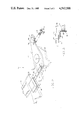
- FIG. 2 is an enlarged, perspective view of the latching mechanism shown in FIG. 1;
- FIG. 3 is a cross-section view of a portion of the latching mechanism as seen along a vertical plane defined by the line 3--3 in FIG. 2;
- FIGS. 4-7 are plan views of the latching mechanism showing the unlatched sequence thereof.
- FIG. 1 there is shown, somewhat schematically, a magnetic disk memory including, generally, an integrally cast housing 10 having an internal mounting surface or base 12.
- the housing encloses a plurality of magnetic disks 14 and an associated head/arm assembly 16 mounted to pivot on the base plate 12 about an axis 18.
- the disks are carried by a spindle 20 driven by a motor 22 beneath the housing base, while the head/arm assembly is actuated relative to the disks by a moving coil motor 24.
- the housing 10 is sealed by a cover (not shown, for clarity) to define a contamination-free enclosure or "clean chamber".
- the head/arm assembly 16 includes a series of stacked arms 26 carrying identical flying head structures 28 pairs of which cooperate with the opposite faces of the magnetic disks in a manner well known in the art. See, for example, U.S. Pat. application Ser. No. 308,277, filed Oct. 5, 1981 and assigned to the present assignee.
- the travel of the head/arm assembly 16 is limited by inner and outer stops 30 and 32, respectively, mounted on the base 12.
- the stops are positioned to be engaged by a post 34 projecting from the undersurface of the lowermost head arm 26.
- the head/arm assembly is shown at its inner limit with the post 34 against the stop 30.
- the heads 28 are in their respective parking zones.
- the head/arm assembly is held in that position by a latch mechanism 40 which is the subject of the present invention.
- the latch mechanism 40 includes, generally, a spring pawl 42 and a latch plate 44.
- the pawl 42 is basically a leaf spring cantilevered from the undersurface of the lowermost head arm and projecting rearwardly therefrom.
- the fixed end of the spring pawl has a horizontal projection 48 secured to the lower head arm 26 by an attachment plate 50 while the free end of the pawl includes a horizontal flange 54 forming a stiffened, L-shaped section 55. Between the stiffened section 55 and the fixed end 48 is a vertical flex section 56 allowing the pawl to be deflected through a small horizontal arc.
- a tab 58 at the outer extremity of the pawl is folded back towards the flange 54 at an acute angle to define a vertical edge or tip 60.
- the latch plate 44 is mounted on the base 12 to pivot about the axis 62.
- the latch plate has inner and outer ends 64 and 66, respectively.
- An extension spring 68 having one end 70 fixed to the base 12 and its other end 72 attached to the latch plate urges the outer end of the plate into engagement with a stop 74.
- the inner end 64 of the latch plate is provided with a step defining a small abutment surface 76 adapted to be engaged by the tip 60 of the pawl.
- the step also defines a corner 78 on the latch plate which corner is located a predetermined distance from the abutment 76 and is positioned to engage the stiffened section 55 during unlatching.
- the latch plate 44 may be mounted directly on the base 12.
- the plate 44 and extension spring 68 are attached to the electronics access cover 80 which, in turn, is secured to the base 12 by screws 82 passing through slotted openings in the cover 80. Final adjustment of the position of the latch plate relative to the pawl 42 is thereby facilitated.
- FIGS. 4-7 The sequence of operation of the latch mechanism from the latched state to the unlatched state is shown in FIGS. 4-7.
- the stiffened section 55 of the spring pawl is seated within the step on the latch plate 44.
- Motion of the head/arm assembly is arrested by the inner limit stop 30 (see FIG. 1) and the latch plate abutment surface 76 against which the tip 60 of the pawl bears.
- the moving coil motor 24 is energized to retract the assembly, that is, to rotate it clockwise about the pivot 18 as shown by the arrows in FIGS. 4-7. Initially, this action causes the latch plate to rotate counterclockwise away from its stop (FIGS. 4-5) as a result of the force applied by the pawl to the abutment surface 76 which force is sufficient to overcome the bias imposed by the extension spring 68.
- the assembly To latch the head/arm assembly, the assembly is driven toward the parking zone. At a small distance therefrom, the pawl engages the inner end 64 of the latch plate and is deflected thereby. During the final travel of the head/arm assembly, the flexed pawl snaps into the step just as the assembly contacts the inner limit stop 30. In the latching sequence, the latch arm, of course, does not pivot.
- the described configurations of the latch plate and spring pawl permit the heads to be operated in the read/write mode very close to the parking zone thereby maximizing the disk surface area available for data storage.
- the heads can be operated within about 0.015-0.20 inch (0.381-0.508 mm) of the parking zone.
- the particular geometry of the components--for example, the depth and length of the latch plate step and the lengths of the latch plate moment arms--as well as the spring constants of the extension spring and pawl are determinative of the specific magnitudes of the forces required to latch and unlatch the head/arm assembly.
- the force required to unlatch the assembly greatly exceeds that needed for latching; for example, the ratio of those forces may be of the order of 20 or 25 to 1.
Abstract
Description
Claims (3)
Priority Applications (1)
| Application Number | Priority Date | Filing Date | Title |
|---|---|---|---|
| US06/497,873 US4562500A (en) | 1983-05-25 | 1983-05-25 | Mechanism for latching magnetic disk memory head/arm assembly in parking zone |
Applications Claiming Priority (1)
| Application Number | Priority Date | Filing Date | Title |
|---|---|---|---|
| US06/497,873 US4562500A (en) | 1983-05-25 | 1983-05-25 | Mechanism for latching magnetic disk memory head/arm assembly in parking zone |
Publications (1)
| Publication Number | Publication Date |
|---|---|
| US4562500A true US4562500A (en) | 1985-12-31 |
Family
ID=23978660
Family Applications (1)
| Application Number | Title | Priority Date | Filing Date |
|---|---|---|---|
| US06/497,873 Expired - Fee Related US4562500A (en) | 1983-05-25 | 1983-05-25 | Mechanism for latching magnetic disk memory head/arm assembly in parking zone |
Country Status (1)
| Country | Link |
|---|---|
| US (1) | US4562500A (en) |
Cited By (69)
| Publication number | Priority date | Publication date | Assignee | Title |
|---|---|---|---|---|
| US4635151A (en) * | 1985-01-25 | 1987-01-06 | Priam Corporation | Rotary actuator having preloaded spring crash stop |
| US4647997A (en) * | 1985-04-29 | 1987-03-03 | Plus Development Corporation | Aerodynamic latch for disk file actuator |
| WO1987001853A1 (en) * | 1985-09-23 | 1987-03-26 | Lapine Technology | Head load mechanism |
| US4654735A (en) * | 1984-11-13 | 1987-03-31 | Ampex Corporation | Latch for head positioning actuator for disc files |
| WO1987002497A1 (en) * | 1985-10-17 | 1987-04-23 | Xebec Development Partners, Ltd. | Transducer positioning mechanism |
| US4692829A (en) * | 1985-09-13 | 1987-09-08 | Quantum Corporation | Magnetically biased aerodynamically released integral safety latch for rigid disk drive |
| US4706142A (en) * | 1984-11-12 | 1987-11-10 | Kabushiki Kaisha Toshiba | Magnetic disk apparatus |
| US4710834A (en) * | 1984-06-26 | 1987-12-01 | Siemens Aktiengesellschaft | Apparatus for positioning a magnetic disk read head with pulse operated detent magnet |
| EP0255240A2 (en) * | 1986-06-30 | 1988-02-03 | Kabushiki Kaisha Toshiba | Magnetic disk device using metallic film disk as data recording medium |
| US4725907A (en) * | 1984-10-19 | 1988-02-16 | Seagate Technology | Carriage latch for a disc drive incorporating inertial lock-up |
| US4742410A (en) * | 1983-12-16 | 1988-05-03 | Josephine County Technology, Inc. | Disk drive system with head protection mechanism |
| US4751595A (en) * | 1984-09-19 | 1988-06-14 | Victor Company Of Japan, Ltd. | Disk drive unit with power-off head parking and locking mechanism |
| US4764831A (en) * | 1985-08-07 | 1988-08-16 | Apple Computer, Inc. | Apparatus and method for retaining a head arm of a disk drive assembly |
| WO1988009552A1 (en) * | 1987-05-29 | 1988-12-01 | Conner Peripherals, Inc. | Latch mechanism for disk drives |
| US4796130A (en) * | 1985-11-30 | 1989-01-03 | Kabushiki Kaisha Toshiba | Carriage lock mechanism of a magnetic recording/reproduction apparatus |
| US4807071A (en) * | 1984-03-12 | 1989-02-21 | Matsushita Electric Industrial Co., Ltd. | Mechanism for preventing damage to the magnetic head and medium of a magnetic recording/reproducing apparatus during transport |
| US4881139A (en) * | 1985-01-25 | 1989-11-14 | Priam Corporation | Latch mechanism for rotary actuator and the like |
| US4903157A (en) * | 1988-03-30 | 1990-02-20 | Miniscribe Corporation | Electromagnet-actuated head latching apparatus |
| US5003422A (en) * | 1988-07-29 | 1991-03-26 | Microscience International Corp. | Magnetic head locking mechanism |
| US5012371A (en) * | 1989-02-22 | 1991-04-30 | Miniscribe Corporation | Disk drive crash stop/actuator latch |
| US5023736A (en) * | 1989-05-22 | 1991-06-11 | Miniscribe Corporation | Magnetic latch for disk drive actuator |
| US5029026A (en) * | 1987-05-29 | 1991-07-02 | Conner Peripherals, Inc. | Disk drive architecture |
| US5043834A (en) * | 1989-02-28 | 1991-08-27 | International Business Machines Corporation | Actuator locking system of disk unit |
| EP0445146A1 (en) * | 1988-11-10 | 1991-09-11 | Conner Peripherals Inc | Voice coil activated disk drive parking device with magnetic bias. |
| US5117318A (en) * | 1988-09-16 | 1992-05-26 | Siemens Aktiengesellschaft | Rotational positioner latch for a magnetic disc storage |
| US5189576A (en) * | 1990-12-19 | 1993-02-23 | Integral Peripherals, Inc. | Rotary inertial latch for disk drive actuator |
| US5216662A (en) * | 1987-05-29 | 1993-06-01 | Conner Peripherals, Inc. | Latch mechanism for disk drives |
| US5296986A (en) * | 1990-12-19 | 1994-03-22 | Integral Peripherals, Inc. | Rotary intertial latch for disk drive actuator to protect against rotational shock force |
| US5363261A (en) * | 1993-11-10 | 1994-11-08 | International Business Machines Corporation | Disk drive actuator latch |
| US5377065A (en) * | 1990-12-19 | 1994-12-27 | Integral Peripherals, Inc. | Miniature hard disk drive for portable computer having a rotary inertial latch for disk drive actuator |
| US5404257A (en) * | 1990-12-19 | 1995-04-04 | Integral Peripherals, Inc. | Rotary inertial latch for disk drive actuator |
| EP0686301A4 (en) * | 1992-11-13 | 1995-07-31 | Maxtor Corp | Locking assembly for the actuator arm of a hard disk drive |
| US5452161A (en) * | 1994-01-21 | 1995-09-19 | Quantum Corp. | Flexible vane latch apparatus for a disk drive |
| US5477403A (en) * | 1992-01-24 | 1995-12-19 | Hewlett-Packard Company | Disk drive having a crash stop detent actuator latch |
| US5579189A (en) * | 1991-09-25 | 1996-11-26 | Integral Peripherals, Inc. | Microminiature hard disk drive |
| WO1997006528A1 (en) * | 1995-08-03 | 1997-02-20 | Syquest Technology, Inc. | Method and apparatus for launching and retracting read-write heads from the medium of a disk drive |
| US5636090A (en) * | 1994-10-17 | 1997-06-03 | International Business Machines Corporation | Tilt limiting inertial actuator latch for a data storage system |
| EP0779611A2 (en) | 1995-12-13 | 1997-06-18 | International Business Machines Corporation | Multiple zone data storage system and method |
| US5668683A (en) * | 1996-05-07 | 1997-09-16 | Quantum Corporation | Counter balanced rotary airlock actuator latch assembly for disk drive |
| US5715118A (en) * | 1996-05-07 | 1998-02-03 | Quantum Corporation | Air actuated latching mechanism rotationally resistant to rotational shock force |
| US5717548A (en) * | 1996-03-04 | 1998-02-10 | Seagate Technology, Inc. | Voice coil actuated bi-stable latch assembly |
| US5729399A (en) * | 1995-12-13 | 1998-03-17 | International Business Machines Corporation | Contact start/stop disk drive with minimized head-disk wear in textured landing zone |
| US5734527A (en) * | 1996-10-07 | 1998-03-31 | International Business Machines Corporation | Disk drive magnetic actuator latch mechanism having a latch lever with magnetic members on each end thereof for latching and unlatching the actuator using voice coil motor magnet |
| US5815350A (en) * | 1997-04-01 | 1998-09-29 | Western Digital Corporation | Head disk assembly with actuator latch vibration damper |
| US6028745A (en) * | 1997-10-06 | 2000-02-22 | Samsung Electronics Co., Ltd. | Head restraint device for disk drive |
| US6091587A (en) * | 1997-08-29 | 2000-07-18 | Iomega Corporation | Inertial latch mechanism for restraining components in a disk drive |
| US6118636A (en) * | 1997-08-29 | 2000-09-12 | Iomega Corporation | Inertial latch mechanism with opposing latch members |
| US6310747B1 (en) | 1991-09-25 | 2001-10-30 | Mobile Storage Technology, Inc. | Method for reducing external signal interference with signals in a computer disk storage system |
| US6417986B1 (en) | 1998-11-16 | 2002-07-09 | Samsung Electronics Co., Ltd. | Impact guard for limiting hard disk movement |
| US6417994B1 (en) | 1999-04-22 | 2002-07-09 | Samsung Electronics, Co., Ltd. | Swage plate with protruded walls to increase retention torque in hard disk applications |
| US6446517B1 (en) | 2000-11-20 | 2002-09-10 | Samsung Electronics Company | Controlled particle deposition in drives and on media for thermal asperity studies |
| US6496362B2 (en) | 2001-05-14 | 2002-12-17 | Iomega Corporation | Method and apparatus for protecting a hard disk drive from shock |
| US6501614B1 (en) | 1999-08-19 | 2002-12-31 | Samsung Electronics Co., Ltd. | Acoustic insulator for controlling noise generated in a mass storage device |
| US6549372B1 (en) | 1998-12-15 | 2003-04-15 | Samsung Electronics Co., Ltd | Device for limiting head movement within a hard disk drive |
| US6590738B2 (en) | 2001-03-01 | 2003-07-08 | Samsung Electronics Co., Ltd. | Particle removal device in a hard disk drive |
| US6624979B1 (en) | 2000-06-09 | 2003-09-23 | Iomega Corporation | Method and apparatus for parking and releasing a magnetic head |
| US6628474B1 (en) | 2000-06-09 | 2003-09-30 | Iomega Corporation | Method and apparatus for electrostatic discharge protection in a removable cartridge |
| US6633445B1 (en) | 2000-06-09 | 2003-10-14 | Iomega Corporation | Method and apparatus for electrically coupling components in a removable cartridge |
| US6674604B1 (en) | 1999-06-30 | 2004-01-06 | Seagate Technology Llc | AC unlatch using grey code detection with zone partitioning |
| US6704161B1 (en) | 1998-11-06 | 2004-03-09 | Samsung Electronics Co. Ltd. | Shock protection skin bumper for a hard disk drive |
| US6717762B1 (en) | 2000-06-09 | 2004-04-06 | Iomega Corporation | Method and apparatus for making a drive compatible with a removable cartridge |
| US6744597B2 (en) | 1999-10-29 | 2004-06-01 | Samsung Electronics Co., Ltd. | Dynamic absorber for an actuator arm in a disk drive |
| US6762908B2 (en) | 2001-06-18 | 2004-07-13 | Samsung Electronics Co., Ltd. | Air razor and disk limiter for a hard disk drive |
| US6779067B2 (en) | 2001-05-14 | 2004-08-17 | Iomega Corporation | Method and apparatus for providing extended functionality for a bus |
| US6781782B2 (en) | 2000-12-21 | 2004-08-24 | Iomega Corporation | Method and apparatus for saving calibration parameters for a removable cartridge |
| US6901525B2 (en) | 2001-05-25 | 2005-05-31 | Iomega Corporation | Method and apparatus for managing power consumption on a bus |
| US6947252B2 (en) | 2000-05-10 | 2005-09-20 | Samsung Electronics Co., Ltd. | Wave stringer for controlling acoustic noise and shock vibration in a storage device |
| US8488280B1 (en) | 2010-06-30 | 2013-07-16 | Western Digital Technologies, Inc. | Disk drive actuator latch including an integrally formed engagement portion that engages and limits rotation of a disk drive actuator |
| US9099153B2 (en) | 2013-04-03 | 2015-08-04 | Western Digital Technologies, Inc. | Storage device with a cover supporting portion |
Citations (6)
| Publication number | Priority date | Publication date | Assignee | Title |
|---|---|---|---|---|
| US3518651A (en) * | 1969-03-10 | 1970-06-30 | Singer Co | Homing control for flying head of magnetic surface storage system |
| US4139874A (en) * | 1976-09-24 | 1979-02-13 | Tokyo Shibaura Electric Co., Ltd. | Magnetic disc recording and/or reproducing apparatus with means to damp and lock disk rotation |
| US4164769A (en) * | 1978-04-24 | 1979-08-14 | Data General Corporation | Cross band coupling for stepper-motor-driven, rigid magnetic disc |
| US4188648A (en) * | 1978-09-05 | 1980-02-12 | Memorex Corporation | Data security apparatus for magnetic recording disc drive |
| US4331989A (en) * | 1980-05-15 | 1982-05-25 | Priam Corporation | Magnetic disc file having dual lock mechanism |
| US4484241A (en) * | 1982-05-17 | 1984-11-20 | International Business Machines Corporation | Automatic lock for head-carriage assembly in a disk file |
-
1983
- 1983-05-25 US US06/497,873 patent/US4562500A/en not_active Expired - Fee Related
Patent Citations (6)
| Publication number | Priority date | Publication date | Assignee | Title |
|---|---|---|---|---|
| US3518651A (en) * | 1969-03-10 | 1970-06-30 | Singer Co | Homing control for flying head of magnetic surface storage system |
| US4139874A (en) * | 1976-09-24 | 1979-02-13 | Tokyo Shibaura Electric Co., Ltd. | Magnetic disc recording and/or reproducing apparatus with means to damp and lock disk rotation |
| US4164769A (en) * | 1978-04-24 | 1979-08-14 | Data General Corporation | Cross band coupling for stepper-motor-driven, rigid magnetic disc |
| US4188648A (en) * | 1978-09-05 | 1980-02-12 | Memorex Corporation | Data security apparatus for magnetic recording disc drive |
| US4331989A (en) * | 1980-05-15 | 1982-05-25 | Priam Corporation | Magnetic disc file having dual lock mechanism |
| US4484241A (en) * | 1982-05-17 | 1984-11-20 | International Business Machines Corporation | Automatic lock for head-carriage assembly in a disk file |
Cited By (83)
| Publication number | Priority date | Publication date | Assignee | Title |
|---|---|---|---|---|
| US4742410A (en) * | 1983-12-16 | 1988-05-03 | Josephine County Technology, Inc. | Disk drive system with head protection mechanism |
| US4807071A (en) * | 1984-03-12 | 1989-02-21 | Matsushita Electric Industrial Co., Ltd. | Mechanism for preventing damage to the magnetic head and medium of a magnetic recording/reproducing apparatus during transport |
| US4710834A (en) * | 1984-06-26 | 1987-12-01 | Siemens Aktiengesellschaft | Apparatus for positioning a magnetic disk read head with pulse operated detent magnet |
| US4751595A (en) * | 1984-09-19 | 1988-06-14 | Victor Company Of Japan, Ltd. | Disk drive unit with power-off head parking and locking mechanism |
| US4725907A (en) * | 1984-10-19 | 1988-02-16 | Seagate Technology | Carriage latch for a disc drive incorporating inertial lock-up |
| US4706142A (en) * | 1984-11-12 | 1987-11-10 | Kabushiki Kaisha Toshiba | Magnetic disk apparatus |
| US4654735A (en) * | 1984-11-13 | 1987-03-31 | Ampex Corporation | Latch for head positioning actuator for disc files |
| US4881139A (en) * | 1985-01-25 | 1989-11-14 | Priam Corporation | Latch mechanism for rotary actuator and the like |
| US4635151A (en) * | 1985-01-25 | 1987-01-06 | Priam Corporation | Rotary actuator having preloaded spring crash stop |
| US4647997A (en) * | 1985-04-29 | 1987-03-03 | Plus Development Corporation | Aerodynamic latch for disk file actuator |
| US4764831A (en) * | 1985-08-07 | 1988-08-16 | Apple Computer, Inc. | Apparatus and method for retaining a head arm of a disk drive assembly |
| US4692829A (en) * | 1985-09-13 | 1987-09-08 | Quantum Corporation | Magnetically biased aerodynamically released integral safety latch for rigid disk drive |
| WO1987001853A1 (en) * | 1985-09-23 | 1987-03-26 | Lapine Technology | Head load mechanism |
| US4703376A (en) * | 1985-09-23 | 1987-10-27 | Lapine Technology | Apparatus for loading and retracting magnetic head in a disk drive |
| WO1987002497A1 (en) * | 1985-10-17 | 1987-04-23 | Xebec Development Partners, Ltd. | Transducer positioning mechanism |
| GB2189643A (en) * | 1985-10-17 | 1987-10-28 | Xebec Dev Partners Ltd | Transducer positioning mechanism |
| US4686595A (en) * | 1985-10-17 | 1987-08-11 | Xebec Development Partners, Ltd. | Apparatus for repositioning a transducer in the absence of electrical current to a drive system |
| US4796130A (en) * | 1985-11-30 | 1989-01-03 | Kabushiki Kaisha Toshiba | Carriage lock mechanism of a magnetic recording/reproduction apparatus |
| EP0255240A3 (en) * | 1986-06-30 | 1989-08-09 | Kabushiki Kaisha Toshiba | Magnetic disk device using metallic film disk as data recording medium |
| EP0255240A2 (en) * | 1986-06-30 | 1988-02-03 | Kabushiki Kaisha Toshiba | Magnetic disk device using metallic film disk as data recording medium |
| WO1988009552A1 (en) * | 1987-05-29 | 1988-12-01 | Conner Peripherals, Inc. | Latch mechanism for disk drives |
| US5216662A (en) * | 1987-05-29 | 1993-06-01 | Conner Peripherals, Inc. | Latch mechanism for disk drives |
| US5029026A (en) * | 1987-05-29 | 1991-07-02 | Conner Peripherals, Inc. | Disk drive architecture |
| US4903157A (en) * | 1988-03-30 | 1990-02-20 | Miniscribe Corporation | Electromagnet-actuated head latching apparatus |
| US5003422A (en) * | 1988-07-29 | 1991-03-26 | Microscience International Corp. | Magnetic head locking mechanism |
| US5117318A (en) * | 1988-09-16 | 1992-05-26 | Siemens Aktiengesellschaft | Rotational positioner latch for a magnetic disc storage |
| EP0445146B1 (en) * | 1988-11-10 | 1995-03-01 | Conner Peripherals, Inc. | Voice coil activated disk drive parking device with magnetic bias |
| EP0445146A1 (en) * | 1988-11-10 | 1991-09-11 | Conner Peripherals Inc | Voice coil activated disk drive parking device with magnetic bias. |
| US5012371A (en) * | 1989-02-22 | 1991-04-30 | Miniscribe Corporation | Disk drive crash stop/actuator latch |
| US5043834A (en) * | 1989-02-28 | 1991-08-27 | International Business Machines Corporation | Actuator locking system of disk unit |
| US5023736A (en) * | 1989-05-22 | 1991-06-11 | Miniscribe Corporation | Magnetic latch for disk drive actuator |
| EP0563267A1 (en) * | 1990-12-19 | 1993-10-06 | Integral Peripherals, Inc. | Rotary inertial latch for disk drive actuator |
| EP0563267A4 (en) * | 1990-12-19 | 1993-11-18 | Integral Peripherals, Inc. | Rotary inertial latch for disk drive actuator |
| US5296986A (en) * | 1990-12-19 | 1994-03-22 | Integral Peripherals, Inc. | Rotary intertial latch for disk drive actuator to protect against rotational shock force |
| US5377065A (en) * | 1990-12-19 | 1994-12-27 | Integral Peripherals, Inc. | Miniature hard disk drive for portable computer having a rotary inertial latch for disk drive actuator |
| US5189576A (en) * | 1990-12-19 | 1993-02-23 | Integral Peripherals, Inc. | Rotary inertial latch for disk drive actuator |
| US5404257A (en) * | 1990-12-19 | 1995-04-04 | Integral Peripherals, Inc. | Rotary inertial latch for disk drive actuator |
| US5448433A (en) * | 1990-12-19 | 1995-09-05 | Integral Peripherals | Disk drive information storage device with baseplate and cover having overlapping edge portions to provide protection from electromagnetic interference |
| US6310747B1 (en) | 1991-09-25 | 2001-10-30 | Mobile Storage Technology, Inc. | Method for reducing external signal interference with signals in a computer disk storage system |
| US5579189A (en) * | 1991-09-25 | 1996-11-26 | Integral Peripherals, Inc. | Microminiature hard disk drive |
| US5477403A (en) * | 1992-01-24 | 1995-12-19 | Hewlett-Packard Company | Disk drive having a crash stop detent actuator latch |
| EP0686301A1 (en) * | 1992-11-13 | 1995-12-13 | Maxtor Corporation | Locking assembly for the actuator arm of a hard disk drive |
| EP0686301A4 (en) * | 1992-11-13 | 1995-07-31 | Maxtor Corp | Locking assembly for the actuator arm of a hard disk drive |
| US5363261A (en) * | 1993-11-10 | 1994-11-08 | International Business Machines Corporation | Disk drive actuator latch |
| US5452161A (en) * | 1994-01-21 | 1995-09-19 | Quantum Corp. | Flexible vane latch apparatus for a disk drive |
| US5636090A (en) * | 1994-10-17 | 1997-06-03 | International Business Machines Corporation | Tilt limiting inertial actuator latch for a data storage system |
| WO1997006528A1 (en) * | 1995-08-03 | 1997-02-20 | Syquest Technology, Inc. | Method and apparatus for launching and retracting read-write heads from the medium of a disk drive |
| US5798884A (en) * | 1995-12-13 | 1998-08-25 | International Business Machines Corporation | Multiple zone data storage system and method |
| EP0779611A2 (en) | 1995-12-13 | 1997-06-18 | International Business Machines Corporation | Multiple zone data storage system and method |
| US6501624B1 (en) | 1995-12-13 | 2002-12-31 | International Business Machines Corporation | Multiple zone data storage system and method |
| US5729399A (en) * | 1995-12-13 | 1998-03-17 | International Business Machines Corporation | Contact start/stop disk drive with minimized head-disk wear in textured landing zone |
| US5717548A (en) * | 1996-03-04 | 1998-02-10 | Seagate Technology, Inc. | Voice coil actuated bi-stable latch assembly |
| US5859751A (en) * | 1996-05-07 | 1999-01-12 | Quantum Corporation | Air actuated latching mechanism rotationally resistant to rotational shock force |
| US5715118A (en) * | 1996-05-07 | 1998-02-03 | Quantum Corporation | Air actuated latching mechanism rotationally resistant to rotational shock force |
| US5668683A (en) * | 1996-05-07 | 1997-09-16 | Quantum Corporation | Counter balanced rotary airlock actuator latch assembly for disk drive |
| US5734527A (en) * | 1996-10-07 | 1998-03-31 | International Business Machines Corporation | Disk drive magnetic actuator latch mechanism having a latch lever with magnetic members on each end thereof for latching and unlatching the actuator using voice coil motor magnet |
| US5815350A (en) * | 1997-04-01 | 1998-09-29 | Western Digital Corporation | Head disk assembly with actuator latch vibration damper |
| US6091587A (en) * | 1997-08-29 | 2000-07-18 | Iomega Corporation | Inertial latch mechanism for restraining components in a disk drive |
| US6118636A (en) * | 1997-08-29 | 2000-09-12 | Iomega Corporation | Inertial latch mechanism with opposing latch members |
| US6028745A (en) * | 1997-10-06 | 2000-02-22 | Samsung Electronics Co., Ltd. | Head restraint device for disk drive |
| US6704161B1 (en) | 1998-11-06 | 2004-03-09 | Samsung Electronics Co. Ltd. | Shock protection skin bumper for a hard disk drive |
| US6417986B1 (en) | 1998-11-16 | 2002-07-09 | Samsung Electronics Co., Ltd. | Impact guard for limiting hard disk movement |
| US6549372B1 (en) | 1998-12-15 | 2003-04-15 | Samsung Electronics Co., Ltd | Device for limiting head movement within a hard disk drive |
| US6417994B1 (en) | 1999-04-22 | 2002-07-09 | Samsung Electronics, Co., Ltd. | Swage plate with protruded walls to increase retention torque in hard disk applications |
| US6674604B1 (en) | 1999-06-30 | 2004-01-06 | Seagate Technology Llc | AC unlatch using grey code detection with zone partitioning |
| US6501614B1 (en) | 1999-08-19 | 2002-12-31 | Samsung Electronics Co., Ltd. | Acoustic insulator for controlling noise generated in a mass storage device |
| US6744597B2 (en) | 1999-10-29 | 2004-06-01 | Samsung Electronics Co., Ltd. | Dynamic absorber for an actuator arm in a disk drive |
| US6947252B2 (en) | 2000-05-10 | 2005-09-20 | Samsung Electronics Co., Ltd. | Wave stringer for controlling acoustic noise and shock vibration in a storage device |
| US6717762B1 (en) | 2000-06-09 | 2004-04-06 | Iomega Corporation | Method and apparatus for making a drive compatible with a removable cartridge |
| US6628474B1 (en) | 2000-06-09 | 2003-09-30 | Iomega Corporation | Method and apparatus for electrostatic discharge protection in a removable cartridge |
| US6624979B1 (en) | 2000-06-09 | 2003-09-23 | Iomega Corporation | Method and apparatus for parking and releasing a magnetic head |
| US6633445B1 (en) | 2000-06-09 | 2003-10-14 | Iomega Corporation | Method and apparatus for electrically coupling components in a removable cartridge |
| US6446517B1 (en) | 2000-11-20 | 2002-09-10 | Samsung Electronics Company | Controlled particle deposition in drives and on media for thermal asperity studies |
| US6781782B2 (en) | 2000-12-21 | 2004-08-24 | Iomega Corporation | Method and apparatus for saving calibration parameters for a removable cartridge |
| US6590738B2 (en) | 2001-03-01 | 2003-07-08 | Samsung Electronics Co., Ltd. | Particle removal device in a hard disk drive |
| US6779067B2 (en) | 2001-05-14 | 2004-08-17 | Iomega Corporation | Method and apparatus for providing extended functionality for a bus |
| US6496362B2 (en) | 2001-05-14 | 2002-12-17 | Iomega Corporation | Method and apparatus for protecting a hard disk drive from shock |
| US6901525B2 (en) | 2001-05-25 | 2005-05-31 | Iomega Corporation | Method and apparatus for managing power consumption on a bus |
| USRE41495E1 (en) | 2001-05-25 | 2010-08-10 | Baker William P | Method and apparatus for managing power consumption on a bus |
| US6762908B2 (en) | 2001-06-18 | 2004-07-13 | Samsung Electronics Co., Ltd. | Air razor and disk limiter for a hard disk drive |
| US8488280B1 (en) | 2010-06-30 | 2013-07-16 | Western Digital Technologies, Inc. | Disk drive actuator latch including an integrally formed engagement portion that engages and limits rotation of a disk drive actuator |
| US9099153B2 (en) | 2013-04-03 | 2015-08-04 | Western Digital Technologies, Inc. | Storage device with a cover supporting portion |
| US9305599B2 (en) | 2013-04-03 | 2016-04-05 | Western Digital Technologies, Inc. | Storage device with a cover supporting portion |
Similar Documents
| Publication | Publication Date | Title |
|---|---|---|
| US4562500A (en) | Mechanism for latching magnetic disk memory head/arm assembly in parking zone | |
| EP0473719B1 (en) | Magnetic latch for disk drive actuator | |
| US4647997A (en) | Aerodynamic latch for disk file actuator | |
| US5734527A (en) | Disk drive magnetic actuator latch mechanism having a latch lever with magnetic members on each end thereof for latching and unlatching the actuator using voice coil motor magnet | |
| US5363261A (en) | Disk drive actuator latch | |
| US5319511A (en) | Aerodynamic actuator latch with magnetic return spring for hard disk drive | |
| US5691860A (en) | Self sealing structure for a removable disk hard disk drive | |
| US5623384A (en) | Landing zone inertial latch | |
| US4654735A (en) | Latch for head positioning actuator for disc files | |
| JPH06259898A (en) | Actuator for driving rotary disk | |
| US5668683A (en) | Counter balanced rotary airlock actuator latch assembly for disk drive | |
| US5768058A (en) | Crash stop airlock mechanism | |
| HK1013171A1 (en) | Disc drive with latch system for the transducer arm | |
| KR19980701412A (en) | PRESSURE DIFFERENTIAL LATCH FOR A DISK DRIVE | |
| US5012371A (en) | Disk drive crash stop/actuator latch | |
| WO1997050080A9 (en) | Crash stop airlock mechanism | |
| US6535359B1 (en) | Inertial latch for mobile and small disc drives | |
| US5715118A (en) | Air actuated latching mechanism rotationally resistant to rotational shock force | |
| KR20020079569A (en) | Pawl latch for ramp loading hard disk drives | |
| US5477403A (en) | Disk drive having a crash stop detent actuator latch | |
| US5717548A (en) | Voice coil actuated bi-stable latch assembly | |
| US5513055A (en) | Motor support assembly for a disk drive | |
| KR20010005850A (en) | Air-flow actuated latch | |
| US6731469B2 (en) | Integral inertial latch design | |
| US20030086208A1 (en) | Bi-stable inertial air latch |
Legal Events
| Date | Code | Title | Description |
|---|---|---|---|
| AS | Assignment |
Owner name: TANDON CORPORATION, A CORP. OF CA. Free format text: ASSIGNMENT OF ASSIGNORS INTEREST.;ASSIGNOR:BYGDNES, PERRY A.;REEL/FRAME:004134/0585 Effective date: 19830513 |
|
| AS | Assignment |
Owner name: WESTERN DIGITAL (SINGAPORE) PTE LTD., A SINGAPORE Free format text: ASSIGNMENT OF ASSIGNORS INTEREST.;ASSIGNOR:TANDON CORPORATION;REEL/FRAME:004864/0053 Effective date: 19880303 Owner name: WESTERN DIGITAL (SINGAPORE) PTE LTD.,SINGAPORE Free format text: ASSIGNMENT OF ASSIGNORS INTEREST;ASSIGNOR:TANDON CORPORATION;REEL/FRAME:004864/0053 Effective date: 19880303 |
|
| REMI | Maintenance fee reminder mailed | ||
| LAPS | Lapse for failure to pay maintenance fees | ||
| STCH | Information on status: patent discontinuation |
Free format text: PATENT EXPIRED DUE TO NONPAYMENT OF MAINTENANCE FEES UNDER 37 CFR 1.362 |
|
| FP | Expired due to failure to pay maintenance fee |
Effective date: 19891231 |
|
| AS | Assignment |
Owner name: BANK OF AMERICA NATIONAL TRUST AND SAVINGS ASSOCIA Free format text: SECURITY INTEREST;ASSIGNOR:WESTERN DIGITAL CORPORATION, A CORP. OF DE;REEL/FRAME:005926/0103 Effective date: 19911031 |