US4580260A - Analog subscriber carrier system terminal with automatic gain and slope correction - Google Patents
Analog subscriber carrier system terminal with automatic gain and slope correction Download PDFInfo
- Publication number
- US4580260A US4580260A US06/606,803 US60680384A US4580260A US 4580260 A US4580260 A US 4580260A US 60680384 A US60680384 A US 60680384A US 4580260 A US4580260 A US 4580260A
- Authority
- US
- United States
- Prior art keywords
- slope
- gain
- controlling
- output
- transmission path
- Prior art date
- Legal status (The legal status is an assumption and is not a legal conclusion. Google has not performed a legal analysis and makes no representation as to the accuracy of the status listed.)
- Expired - Fee Related
Links
Images


Classifications
-
- H—ELECTRICITY
- H04—ELECTRIC COMMUNICATION TECHNIQUE
- H04B—TRANSMISSION
- H04B3/00—Line transmission systems
- H04B3/02—Details
- H04B3/04—Control of transmission; Equalising
- H04B3/10—Control of transmission; Equalising by pilot signal
Definitions
- This invention relates to FDM (frequency division multiplexed) subscriber carrier systems used in telecommunications and, more particularly, to analog terminals which automatically adapt to various changes in cable characteristics. Further, the gain and slope correction for both directions of transmission are obtained by cross-regulation as the pilot signals are only transmitted in the high frequency band.
- the carrier modulation employed in analog carrier systems is typically double sideband (DSB-AM) or single sideband (SSB-AM).
- Single-sideband modulation occupies far less bandwidth than DSB-AM for the same number of channels, but it has the disadvantage of being more sensitive to changes in gain or attenuation versus frequency (i.e. slope) in the transmission path.
- Fixed equalizers have often been used to compensate for this (frequency roll-off) slope characteristic, and most are manually adjustable so that cable length variations in spacing between end terminals may be accommodated.
- attenuation characteristics of insulated cables as a result of temperature and weather conditions.
- variable gain amplifier would be sufficient to compensate for the gain variation.
- the frequency slope of the commonly used transmission cables also changes with variations in ambient conditions.
- the slope equalization characteristic also be varied for the overall gain versus frequency characteristic to remain flat.
- the frequency band is pre-equalized.
- the amount of gain and slope correction that is needed must be based upon the level of the incoming (high frequency path) pilots. With minor variations the gain and slope settings are often adjusted to the same values as those in the other direction. Such an adjustment is a compromise and thus errors are introduced. Some of these errors may be manually adjusted during initial alignment using switched equalizer networks which are included for this purpose. However, the accuracy of regulation is poor particularly when changes in temperature are considered.
- the frequency response should be flat to within ⁇ 0.25 dB for each channel for cable losses of 35 dB ⁇ 5 dB and for cable gauges of 19, 22, 24 and 26 which are operating in ambient temperature conditions of from -40° C. to +65° C. Further, no manual adjustment should be necessary. It is an object of this invention to provide a subscriber carrier system having improved gain stability over a wide range of ambient temperatures.
- Prior art carrier systems also have the disadvantage that if one or both system pilots fail, the gain and slope amplifier settings often are increased to the maximum possible levels which usually interrupts transmission. It is a further object of this invention to provide a subscriber carrier system where the gain and slope amplifier settings are stored in memory, so that system pilot failures will not result in an interruption of transmission.
- An analog subscriber carrier duplex remote terminal is disclosed with two amplifiers in each transmission path.
- a gain amplifier sets the levels to a predetermined value, and a slope amplifier corrects for undesirable frequency slope. Because there are only two system pilots and both are communicated in only one direction, the gain and slope settings of the return direction are accurately determined by an encoder which optimizes the proper level settings by using theoretical and empirical transmission characteristics which are stored or coded in the encoder.
- the encoder is an 8-bit microprocessor that calculates the proper level settings from the detected pilots.
- FIG. 1 is a block diagram illustrating the basic elements of a subscriber carrier remote terminal
- FIG. 2A is a frequency allocation diagram showing the channel positioning for the low frequency (remote terminal to central office) direction of transmission;
- FIG. 2B is a frequency allocation diagram showing the channel positioning for the high frequency (central office to remote terminal) direction of transmission.
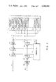
- FIG. 3 is a block diagram of a remote terminal in a subscriber carrier system which employs an embodiment of the instant invention
- FIG. 4 is a block diagram which illustrates one technique by which the cable characteristic predictor encoder and timing (80) may be effectuated.
- FIG. 5 is a timing diagram which illustrates the timing sequence for the switches (S1), (S2), (S3) and (S4) of FIGS. 3 and 4.
- two frequency bands are used to carry the multiplexed channels: one upper band (88 kHz-160 kHz) and one lower band (12 kHz-68 kHz), such as shown in FIG. 2.
- the upper band is usually used in the central office to remote terminal direction, and the lower band in the reverse direction.
- the upper band could include ten channels with a channel spacing as shown in FIG. 2B plus the low frequency pilot 20 as well as the high frequency pilot 22.
- a remote terminal shown generally in FIG. 1, accepts the high frequency band channels and the two pilots and adjusts the gain and slope equalization amplifiers 24 and 26 so as to provide an output signal at the proper levels for transmission along path 10 to a channel bank 7.
- the received FDM channel signals on output path 10 are fed to the individual receiver channel units, shown generally as 7A, 7C, 7E, and 7S, which are all connected to the same path 10.
- Channel filters (not shown) would pick off the appropriate signals associated with a particular channel for further demodulation and processing to forward them to subscriber drops.
- the individual channel signals are processed and stacked in the lower frequency band for transmission to the central office.
- Each of the transmit channel units (7B, 7D, 7F, and 7T) are bridged onto path 14.
- the transmit signals must be pre-equalized, by gain and slope networks or amplifiers 130 and 118.
- a cross-regulation is employed to provide the approximate gain and slope equalization condition for amplifiers 118 and 130. If the prediction for the pre-equalization at the terminal is correct, the level at the output of each carrier channel will be substantially the same and will be very close to the standard level desired.
- the cross-regulation employed in prior art carrier systems is a compromise and does not always provide the appropriate pre-equalization condition.
- One arrangement by which the predicted pre-equalization condition closely approximates the desired value is shown in FIG. 3.
- FIG. 3 it may be seen that the input and output paths are numbered in accordance with FIG. 1. This was done to provide a basis for orientation of FIG. 3 with the overall subscriber carrier system. It is to be understood that the manner in which the cross-regulation is derived in order to provide a very precise prediction for the pre-equalization is quite different from that employed in prior art systems.
- the high frequency channels including the pilots 20 and 22 are applied to the input of gain amplifier 24, then to slope correction amplifier 26, then to line amplifier 28 and then via junction 30 to output path 10.
- the corrected line signals are applied via path 32 and junction 34 to the inputs of attenuators 36 and 38, respectively.
- the attenuator 36 is selected to provide a predetermined amplitude at the output of the low frequency pick off filter 40 when the low frequency pilot is at the proper level at output 10.
- the attenuation of attenuator 38 is selected so as to provide the same predetermined amplitude for the high frequency pilot which appears at the output of the high frequency pick off filter 42 when this pilot is at the proper level at output 10.
- the low frequency and high frequency pilots are applied via paths 44 and 46, respectively, to contacts 48 and 50 of switch 54.
- the wiper arm 52 of switch 54 is connected to contact 48 by the S1 pulse and to contact 50 by the S2 pulse (shown in FIG. 5).
- a window detector 62 recognizes four DC amplitude conditions. First are those amplitudes below a threshold level. Second are those amplitudes within the "window" between the low threshold level and the high threshold level. (Those levels which appear within the window indicate an area of normal operation, i.e., no change.) Third there are those amplitude levels that are above the high threshold level.
- the adjustment range of the repeater covers a ⁇ 5 dB range about 35 dB of line loss.
- a DC reference point is set in the window detector corresponding to greater than 40 dB of line loss.
- the window detector in order to accommodate the four different DC amplitude conditions, uses a two digit binary coded output signal.
- window detector 62 converts the amplitude of the DC signal on path 60 into a binary coded signal on path 64 which is applied via wiper contact 66 of switch 72 to either contact 68 or 70.
- the timing of the connection of the wiper contact 66 to either contact 68 or 70 is such as to put the binary code on path 74 for the low frequency pilot and on path 76 for the high frequency pilot.
- These two binary coded signals represent the status of the low frequency and high frequency pilots following gain and slope correction.
- the cable characteristic predictor encoder and timing circuit 80 use the pilot status signals on paths 74 and 76 to identify the cable characteristics of the transmission path and to predict the low frequency response needed to set the gain and slope amplifiers in the station to central office path.
- a reference voltage is applied via resistor 94 to the other input of operational amplifier 92 and to the emitter of current source 96.
- the periodic closing of switch 88 refreshes storage capacitor 90 and thus maintains the value of the control voltage from one sample period to the next.
- the control voltage is applied to current source 96 to control the gain of amplifier 24.
- the next control voltage signal is applied to slope amplifier 26.
- the control voltage from digital to analog converter 84 is applied via switch 98 to the input of operational amplifier 102 as well as to the storage capacitor 100.
- a reference voltage is applied via resistor 104 to the other input of operational amplifier 102 and to the emitter of current source 106.
- the collector of current source 106 is applied to the slope amplifier 26 in order to provide appropriate correction for the gain v. frequency characteristic.
- One way in which the gain (attenuation) with frequency may be adjusted is to vary the Q of the network in the amplifier circuit as is well known.
- gain and slope correction is provided in a manner similar to that disclosed for the high frequency direction of transmission.
- gain and slope correction is provided in a manner similar to that disclosed for the high frequency direction of transmission.
- a more complex and very accurate technique is used instead of simply setting the gain and slope of amplifiers 130 and 118 to be the same as the amplifier settings of the other direction.
- a more complex and very accurate technique is used. In order to arrive at more precise gain and slope settings, it was necessary to emulate (first theoretically then empirically) the transmission characteristics of various cables over a range of temperature variations.
- ⁇ c (2 ⁇ ) 125 kHz
- ⁇ z (2 ⁇ )f z
- f z is the zero frequency of the cable response function G(S).
- ⁇ o (2 ⁇ ) 100 kHz
- ⁇ 1 (2 ⁇ ) 125 kHz
- the high group gain microprocessor code is solely a function of high group gain setting GH (which is derived from the low frequency pilot), and the high group slope microprocessor code is solely a function of high group slope setting SH (which is derived from the high frequency pilot).
- the high group gain microprocessor code CGH and the high group slope microprocessor codes CSH are derived.
- the required values for the low frequency gain and slope are obtained solely from the two system pilots received in the high frequency direction.
- the microprocessor issues a set of commands to the four current sources 96, 106, 116, and 128. Each presets all the line amplifiers to some nominal level (35 dB of gain with 6 dB of slope over 88-160 kHz). Then the pilot levels are examined so that the proper high group gain and slope settings (CGH and CSH) can be determined. If the pilot levels are too high the microprocessor changes the coded current setting to reduce the high group gain setting of amp 24. Once the detected pilot levels are in the proper "window,” the microprocessor sets the high group slope (CSH) at output 82 by varying the slope and comparing the detected pilot levels. Once the two pilots are within a predetermined amplitude of each other, the microprocessor maintains that current drain to the high group amplifiers. So in the high group direction there is no involved computation of levels or values for the determination of the gain and slope settings.
- CGH and CSH high group gain and slope settings
- the digital microprocessor codes for the high group gains and slope settings are stored in the microprocessor.
- the microprocessor then computes the required values for CSL and CGL from the equations (6) and (7), which are simply functions of CGH and CSH.
- the microprocessor is often the better alternative to two ROM devices to implement this function.
- equations 4, 5, 6 and 7 may be used to derive the predictions for the low frequency group gain and slope.
- a discrete circuit could be implemented to perform the "calculations" of equations 4, 5, 6, and 7.
- these four equations may be expressed differently by converting to the same log base 2 and taking the antilog of equations 4 and 5. (Note log 2 N ⁇ 3.32 log 10 N).
- the numerical constants, 11.3, 9, etc. may be implemented as simply DC voltages as shown in FIG. 4. Similarly the subtraction of terms may be performed by differential amplifiers (148, 160, and 162).
- the encoder 136 performs the antilog function (Alog 2 N) to obtain the required 8-bit word which goes to the D/A converter 84.
- the Converter and Storage units 132 and 138 convert the two bit codes from the window detector to a DC voltage.
- the code for the high frequency pilot is applied via path 76 to the input of converter and storage 138 and thence via path 140 to switch 141 at pulse time S2 to encoder 136 where it is converted into a binary code and sent as a parallel byte along path 82.
- the control of the gain and slope of the high frequency path is effected as is described in FIG. 3.
- the equations 6b and 7b are solved for log(CSL) and log(CGL).
- the signal on path 150 represents log(CGL).
- switch 152 closes in the appropriate time interval to apply log(CGL) to the encoder 136 which extracts the desired code for the low frequency gain setting.
- the code for the low frequency slope setting is derived through the two subtractors 160 and 162, switch 163, and encoder 136.
- the use of the storage capacitors 90, 100, 110 and 122 as shown in FIG. 3 provide the control signal during the time when the associated switch is open.
- the microprocessor just continues to recharge the capacitors (refresh) whenever the associated switch is open in order to hold the output signals constant.
- the capacitors controlling the current sources will not be refreshed, and therefore, the amplifiers will seek a maximum gain setting.
Abstract
Description
______________________________________ Bit 1Bit 2 Status ______________________________________ 1 1 Withinwindow 1 0 Above window 0 1 Below window 0 0 No pilots ______________________________________
log.sub.10 (CGH)=3.4-0.94log.sub.10 (GH) (4)
log.sub.10 (CSH)=2.7-2.56log.sub.10 (SH) (5)
CSL=Alog.sub.2 (85/256+log.sub.2 (CGH))-Alog.sub.2 (log.sub.2 (CSH)-241/256)+12 (6)
CGL=Alog.sub.2 (12+163/256-log.sub.2 (CGH)) (7)
CGH=Alog(11.3-0.94log(GH)) (4a)
CSH=Alog(9-2.56log(SH)) (5a)
CSL=Alog(85/256+log(CGH))-Alog(log(CSH)-241/256)+12 (6a)
CGL=Alog(12+163/256-log(CGH)) (7a)
log(CGH)=11.3-0.94log(GH) (4b)
log(CSH)=9-2.56log(SH) (5b)
log(CSH)=log(CGH)-log(CSH)=log12+326/256 (6b)
log(CGL)=12+163/256-log(CGH) (7b)
Claims (4)
Priority Applications (1)
| Application Number | Priority Date | Filing Date | Title |
|---|---|---|---|
| US06/606,803 US4580260A (en) | 1984-05-03 | 1984-05-03 | Analog subscriber carrier system terminal with automatic gain and slope correction |
Applications Claiming Priority (1)
| Application Number | Priority Date | Filing Date | Title |
|---|---|---|---|
| US06/606,803 US4580260A (en) | 1984-05-03 | 1984-05-03 | Analog subscriber carrier system terminal with automatic gain and slope correction |
Publications (1)
| Publication Number | Publication Date |
|---|---|
| US4580260A true US4580260A (en) | 1986-04-01 |
Family
ID=24429532
Family Applications (1)
| Application Number | Title | Priority Date | Filing Date |
|---|---|---|---|
| US06/606,803 Expired - Fee Related US4580260A (en) | 1984-05-03 | 1984-05-03 | Analog subscriber carrier system terminal with automatic gain and slope correction |
Country Status (1)
| Country | Link |
|---|---|
| US (1) | US4580260A (en) |
Cited By (7)
| Publication number | Priority date | Publication date | Assignee | Title |
|---|---|---|---|---|
| US5724344A (en) * | 1996-04-02 | 1998-03-03 | Beck; William Federick | Amplifier using a single forward pilot signal to control forward and return automatic slope circuits therein |
| US20030066088A1 (en) * | 1997-12-26 | 2003-04-03 | Samsung Electronics Co., Ltd. | Bidirectional trunk amplifier and cable modem for cable hybrid fiber and coax network which utilizes an upstream pilot signal |
| US20040151237A1 (en) * | 2000-05-31 | 2004-08-05 | Bitrage, Inc. | Satellite communications system |
| US6823001B1 (en) | 2000-05-31 | 2004-11-23 | Bitrage, Inc. | Dual stage communication processor |
| US7149242B1 (en) | 2000-05-31 | 2006-12-12 | Bitrage, Inc. | Communications system for improving transmission rates and transmission distances of data signals across communications links |
| US20110194616A1 (en) * | 2008-10-01 | 2011-08-11 | Nxp B.V. | Embedded video compression for hybrid contents |
| US10218544B1 (en) * | 2017-12-07 | 2019-02-26 | Global Technology Inc. | Adjustable electric control equalization circuit of cable television networks |
Citations (5)
| Publication number | Priority date | Publication date | Assignee | Title |
|---|---|---|---|---|
| US2300415A (en) * | 1941-04-26 | 1942-11-03 | Bell Telephone Labor Inc | Transmission control |
| US2758281A (en) * | 1951-05-21 | 1956-08-07 | Ericsson Telefon Ab L M | Variable attenuation correcting electric impedance network |
| US4087639A (en) * | 1977-01-28 | 1978-05-02 | Reliance Telecommunication Electronics Company | Amplitude modulated telephone carrier systems |
| US4136267A (en) * | 1976-04-06 | 1979-01-23 | International Standard Electric Corporation | Transmission systems |
| US4281408A (en) * | 1978-06-08 | 1981-07-28 | U.S. Philips Corporation | Digital signal processing arrangement for controlling the level of a frequency-division multiplex signal |
-
1984
- 1984-05-03 US US06/606,803 patent/US4580260A/en not_active Expired - Fee Related
Patent Citations (5)
| Publication number | Priority date | Publication date | Assignee | Title |
|---|---|---|---|---|
| US2300415A (en) * | 1941-04-26 | 1942-11-03 | Bell Telephone Labor Inc | Transmission control |
| US2758281A (en) * | 1951-05-21 | 1956-08-07 | Ericsson Telefon Ab L M | Variable attenuation correcting electric impedance network |
| US4136267A (en) * | 1976-04-06 | 1979-01-23 | International Standard Electric Corporation | Transmission systems |
| US4087639A (en) * | 1977-01-28 | 1978-05-02 | Reliance Telecommunication Electronics Company | Amplitude modulated telephone carrier systems |
| US4281408A (en) * | 1978-06-08 | 1981-07-28 | U.S. Philips Corporation | Digital signal processing arrangement for controlling the level of a frequency-division multiplex signal |
Cited By (7)
| Publication number | Priority date | Publication date | Assignee | Title |
|---|---|---|---|---|
| US5724344A (en) * | 1996-04-02 | 1998-03-03 | Beck; William Federick | Amplifier using a single forward pilot signal to control forward and return automatic slope circuits therein |
| US20030066088A1 (en) * | 1997-12-26 | 2003-04-03 | Samsung Electronics Co., Ltd. | Bidirectional trunk amplifier and cable modem for cable hybrid fiber and coax network which utilizes an upstream pilot signal |
| US20040151237A1 (en) * | 2000-05-31 | 2004-08-05 | Bitrage, Inc. | Satellite communications system |
| US6823001B1 (en) | 2000-05-31 | 2004-11-23 | Bitrage, Inc. | Dual stage communication processor |
| US7149242B1 (en) | 2000-05-31 | 2006-12-12 | Bitrage, Inc. | Communications system for improving transmission rates and transmission distances of data signals across communications links |
| US20110194616A1 (en) * | 2008-10-01 | 2011-08-11 | Nxp B.V. | Embedded video compression for hybrid contents |
| US10218544B1 (en) * | 2017-12-07 | 2019-02-26 | Global Technology Inc. | Adjustable electric control equalization circuit of cable television networks |
Similar Documents
| Publication | Publication Date | Title |
|---|---|---|
| US4583220A (en) | Analog subscriber carrier system repeater with automatic gain and slope correction | |
| US4254305A (en) | Current limited subscriber line feed circuit | |
| US3962637A (en) | Ultrafast adaptive digital modem | |
| US4797898A (en) | Method and apparatus for equalization of data transmission system | |
| US4096362A (en) | Automatic cable balancing network | |
| US5796778A (en) | Receiver circuit having adaptive equalizer with characteristics determined by signal envelope measurement and method therefor | |
| KR100191738B1 (en) | Equalizer with line length detection | |
| US5194822A (en) | Automatic gain control method and device for a variable gain amplifier and application thereof to controlling the gain of a tuner, in particular for a videocommunication network | |
| US4580260A (en) | Analog subscriber carrier system terminal with automatic gain and slope correction | |
| US4996497A (en) | Cable compensation circuit | |
| KR20030047902A (en) | Programmable gain amplifier for use in a data network | |
| US5960333A (en) | Circuitry and method for power calibration | |
| US4201959A (en) | Automatic equalization system | |
| US4281408A (en) | Digital signal processing arrangement for controlling the level of a frequency-division multiplex signal | |
| EP0092570B1 (en) | Method of providing adaptive echo cancellation in transmission of digital information in duplex, and apparatus for performing the method | |
| WO1984001641A1 (en) | Adaptive filter including controlled tap gain coefficient drift | |
| US4178569A (en) | Hybrid for two-wire full-duplex transmission of digital signals | |
| US2231538A (en) | Transmission control | |
| US4087639A (en) | Amplitude modulated telephone carrier systems | |
| US4910768A (en) | Automatic balancing circuit for longitudinal transmission system | |
| US2876283A (en) | Transmission regulation | |
| US4028644A (en) | System equalization for repeatered submarine cable system | |
| US2920281A (en) | Noise suppressor | |
| US3368167A (en) | Apparatus for equalizing a transmission system | |
| US4899365A (en) | Apparatus and method for adaptive amplitude equalization |
Legal Events
| Date | Code | Title | Description |
|---|---|---|---|
| AS | Assignment |
Owner name: GTE COMMUNICATION SYSTEMS CORPORATION Free format text: ASSIGNMENT OF ASSIGNORS INTEREST.;ASSIGNORS:BLACKBURN, TOM L.;FARRELL, DAVID J.;REEL/FRAME:004296/0673 Effective date: 19840426 |
|
| AS | Assignment |
Owner name: AG COMMUNICATION SYSTEMS CORPORATION, 2500 W. UTOP Free format text: ASSIGNMENT OF ASSIGNORS INTEREST.;ASSIGNOR:GTE COMMUNICATION SYSTEMS CORPORATION;REEL/FRAME:005060/0501 Effective date: 19881228 |
|
| FPAY | Fee payment |
Year of fee payment: 4 |
|
| FEPP | Fee payment procedure |
Free format text: PAYOR NUMBER ASSIGNED (ORIGINAL EVENT CODE: ASPN); ENTITY STATUS OF PATENT OWNER: LARGE ENTITY |
|
| FEPP | Fee payment procedure |
Free format text: PAYOR NUMBER ASSIGNED (ORIGINAL EVENT CODE: ASPN); ENTITY STATUS OF PATENT OWNER: LARGE ENTITY Free format text: PAYER NUMBER DE-ASSIGNED (ORIGINAL EVENT CODE: RMPN); ENTITY STATUS OF PATENT OWNER: LARGE ENTITY |
|
| FPAY | Fee payment |
Year of fee payment: 8 |
|
| REMI | Maintenance fee reminder mailed | ||
| LAPS | Lapse for failure to pay maintenance fees | ||
| FP | Lapsed due to failure to pay maintenance fee |
Effective date: 19980401 |
|
| STCH | Information on status: patent discontinuation |
Free format text: PATENT EXPIRED DUE TO NONPAYMENT OF MAINTENANCE FEES UNDER 37 CFR 1.362 |