US4596436A - Electrical connector housing assembly comprising housing frame containing housing modules - Google Patents
Electrical connector housing assembly comprising housing frame containing housing modules Download PDFInfo
- Publication number
- US4596436A US4596436A US06/715,432 US71543285A US4596436A US 4596436 A US4596436 A US 4596436A US 71543285 A US71543285 A US 71543285A US 4596436 A US4596436 A US 4596436A
- Authority
- US
- United States
- Prior art keywords
- module
- frame
- modules
- electrical connector
- housing assembly
- Prior art date
- Legal status (The legal status is an assumption and is not a legal conclusion. Google has not performed a legal analysis and makes no representation as to the accuracy of the status listed.)
- Expired - Fee Related
Links
Images


Classifications
-
- H—ELECTRICITY
- H01—ELECTRIC ELEMENTS
- H01R—ELECTRICALLY-CONDUCTIVE CONNECTIONS; STRUCTURAL ASSOCIATIONS OF A PLURALITY OF MUTUALLY-INSULATED ELECTRICAL CONNECTING ELEMENTS; COUPLING DEVICES; CURRENT COLLECTORS
- H01R13/00—Details of coupling devices of the kinds covered by groups H01R12/70 or H01R24/00 - H01R33/00
- H01R13/64—Means for preventing incorrect coupling
-
- H—ELECTRICITY
- H01—ELECTRIC ELEMENTS
- H01R—ELECTRICALLY-CONDUCTIVE CONNECTIONS; STRUCTURAL ASSOCIATIONS OF A PLURALITY OF MUTUALLY-INSULATED ELECTRICAL CONNECTING ELEMENTS; COUPLING DEVICES; CURRENT COLLECTORS
- H01R13/00—Details of coupling devices of the kinds covered by groups H01R12/70 or H01R24/00 - H01R33/00
- H01R13/62—Means for facilitating engagement or disengagement of coupling parts or for holding them in engagement
- H01R13/639—Additional means for holding or locking coupling parts together, after engagement, e.g. separate keylock, retainer strap
Definitions
- This invention relates to electrical connector assemblies of the type comprising a frame which contains a plurality of connector modules, each of which has electrical terminals therein.
- the invention particularly is concerned with improved retaining means for retaining the modules in the frame and for retaining the contact terminals in the modules.
- the invention also relates to module keying systems for keying the individual modules to particular module-receiving openings in the frame.
- electrical connector refers to a housing containing a plurality of electrical contact terminals which is intended to be coupled or mated to a complementary electrical connector to form a connector assembly.
- One type of electrical connector is in the form of a housing assembly which consists of a frame or shell having one or more module-receiving openings in which is positioned a connector module.
- Housing assemblies of this type are being used to an increasing extend in electrical harnesses and have advantages over conventional connector housings under some circumstances.
- the housing frame or shell can be of a standard configuration and size and the individual modules can be designed to accommodate different types or sizes of terminals so that standardization is achieved of the exterior dimensions and shape of the housing while permitting the use of many different types of terminals in the housing.
- harnesses can be manufactured by producing individual modules containing all of the types of terminals required in the harness and the individual modules can then be brought together in a standard type of housing frame.
- Connector housing assemlbies of the type comprising a frame and modules require a system for removably retaining the individual modules in the frame in a positive manner which nonetheless permits removal of the individual modules for servicing or repair.
- the present invention is directed to the achievement of an improved module-retaining means for retaining individual connector modules in a housing frame of a connector housing assembly.
- the invention is directed to the achievement of an improved retaining system for retaining individual contact terminals in their cavities in an electrical connector. Terminals are frequently retained in the cavities of an electrical connector by means of lances or tangs on the terminals which engage shoulders in the cavities.
- lances or tangs on the terminals which engage shoulders in the cavities.
- the lances are somewhat flimsy and can be damaged during normal handling prior to their being placed in the connector and the terminals may be removed if a tensile force is applied to the wire to which the terminal is crimped.
- the invention comprises an electrical connector housing assembly of the type comprising a housing frame and at leat one housing module of insulating material contained in the frame.
- the housing assembly has a mating face, a rear face which is directed oppositely with respect to the mating face, and external wall portions which extend from the mating face to the rear face.
- At least one module-receiving opening extends through the housing from the rear face to the mating face and a housing module is contained in the opening.
- the module has a module mating face, a module rear face, and module external wall portions.
- At least one contact-receiving cavity extends through the module and a contact terminal is contained in the cavity.
- the connector housing assembly is particularly characterized in that a removable locking key extends into the external wall portions of the frame, into the module-receiving opening, and through the module.
- the locking key also extends through the contact-receiving cavity in the module.
- the locking key and the module have opposed module-retaining surface portions which prevent removal of the module from the frame.
- the locking key and the terminal have opposed contact-retaining surface portions which prevent removal of the terminal from the terminal-receiving cavity.
- the external wall portions of the frame comprise first and second oppositely facing frame sidewalls and oppositely facing frame endwalls, and the locking key extends into the frame from the first frame sidewall.
- a plurality of module-receiving openings may be provided in the frame with the openings in side-by-side relationship in a row which is between the frame endwalls, and a locking key may then be provided for each of the module-receiving openings, the locking keys extending into the frame from one of the frame sidewalls.
- one or more of the modules has at least two contact-receiving cavities extending therethrough, each of the cavities having a contact terminal therein, and the locking key extends through all of the contact-receiving cavities.
- Each of the terminals and the locking key have opposed contact-retaining surface portions for retaining the terminals in the cavities.
- the module has internal wall portions which are between the contact-receiving cavities and the locking key extends through the internal wall portions and projects into each of the cavities.
- two modules are contained in at least one of the module-receiving openings and the locking key extends through both of the modules and through the contact-receiving cavitives in both of the modules.
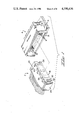
- FIG. 1 is a perspective view showing a connector housing assembly in accordance with the invention and a complementary connector housing assembly.
- FIG. 2 is a perspective view showing a connector housing assembly having the modules and the locking keys exploded from the frame member.
- FIG. 3 is a top plan view of the housing assembly.
- FIG. 4 is a view looking in the direction of the arrows 4--4 of FIG. 3.
- FIG. 5 is a view looking in the direction of the arrows 5--5 of FIG. 4 but showing modules contained in the module-receiving openings of the frame.
- FIGS. 6 and 7 are views looking in the direction of the arrows 6--6 and 7--7 of FIG. 3.
- FIGS. 8 and 9 are views looking in the direction of the arrows 8--8 and 9--9 of FIG. 2 and showing the rearward faces of two of the modules which are contained in the frame.
- FIGS. 1 and 2 An electrical connector housing assembly 2 in accordance with the invention, FIGS. 1 and 2, is intended to be coupled to a complementary connector housing 4 which is mounted on a circuit board 6.
- the complementary connector housing 4 contains a plurality of small contact pins 8 and larger contact pins 10 which extend forwardly from its mating face 12.
- a hood 14 surround the mating face 12, FIG. 5, and the connector housing assembly 2 is dimensioned to be received in this hood when the two connector assemblies are coupled to each other.
- the housing assembly 2 has a mating face 16, a housing assembly rear face 18, upper and lower housing assembly sidewalls 20, 22, and oppositely facing housing assembly endwalls 24.
- the housing assembly is composed of a housing frame 26 which contains one module 28 and a plurality of associated pairs of modules 30, 32.
- Module-receiving openings 34 extend through the frame and re dimensioned to receive a pair of modules 30, 32 and a single module-retaining opening 35 is provided for the module 28.
- the module 28 has upper and lower module sidewalls 36, 38 and oppositely facing module endwals 40.
- Spaced-apart ribs are provided on the lower module sidewalls as shown at 39 and are received in spaced-apart channels 41 on the floor of the module-receiving opening. These channels have inner ends which are spaced from the mating face thereby to provide a forward stop for the module when it is inserted into the module-receiving opening 35.
- Terminal-receiving cavities 46 extend through the module 28 between the mating face 42 and the rear face 44 thereof.
- the disclosed embodiment has three such terminals intended to be mated with the three contact pins in the complementary housing 4.
- Each of the terminals has a crimp portion 50 by means of which is secured to a wire, an intermediate collar 52, and a socket portion 54 which is adjacent to the mating face. It will be noted that the socket has rearwardly extending lances, see FIG. 5, which will retain the terminal in the cavity. However, and as will be described below, in accordance with the present invention an additional and more reliable terminal-retaining system is provided.
- the module 28 has a vertically extending internal wall 56 which is between the cavities and an opening 58 is provided in the upper sidewall 36 which extends into this internal wall 56.
- An opening 60 is provided in the upper or first frame sidewall in alignment with the opening 58.
- the openings 58, 60 are dimensioned to receive a locking key 62 which has a head 64 that is received in the enlarged upper end of the opening 60 when the key is assembled to the frame and the module, see FIG. 6.
- the key and the internal wall of the module have a projection and recess as shown at 66, to retain the key in the openings when it is assembled to the module and the frame. As will be apparent from FIG.
- the key can be removed by inserting the blade of a screwdriver or the like beneath the head 64 and raising the key upwardly.
- the key serves as a retainer for the terminals in the cavities 46 as shown in FIG. 5.
- the key has portions 68 which project into the terminal-receiving cavities and which are behind the collars 52 of the terminals so the terminals cannot be withdrawn from the cavities. Forward motion of the terminals is of course prevented by the constricted intermediate portions of the cavities.
- the key 62 also serves to retain the module in the module-receiving opening by virtue of the opposed shoulder surfaces shown in FIG. 6 at 94 and 95, between the shell and the key and the inner wall of the module and the key.
- the modules 30, 32 are similar to each other and are substantial mirror images of each other, and the same reference numerals will therefore be used to identify the same structural features of the two modules.
- the module 30 and the module 32 have terminal-receiving cavities 70 which extend through the module from the mating face 71 to the rear face 73 thereof.
- the terminals 72 in the cavities see FIG. 5, have socket portions 74 and intermediate portions 76 which define shoulders that cooperate with the locking keys 88. It will be noted that these terminals also have lances for retention purposes although the locking key 88 serves as a more positive and reliable retaining means as will be described.
- Each of the modules 30, 32 has an endwall 78 and an endwall 80.
- the endwalls 78 are against each other and aligned recesses 82 in these endwalls define an opening extending downwardly through the pair of modules which receive the locking key as illustrated in FIGS. 5 and 7.
- the key-receiving recess extends entirely through the pair of modules 30, 32 from the top sidewalls 84 of the modules to the bottom sidewalls 85 thereof.
- An opening 86 is provided in the shell for the key 88 which has an enlarged upper end 90.
- the opening is also enlarged at the upper end, as shown in FIG. 7, so that the key can be removed as previously described.
- a detect system is shown at 92 in FIG. 7 to retain the key in the modules.
- the key prevents removal of the modules from the module-receiving opening by virtue of the face that the key and the modules have opposed shoulder surfaces as shown at 98 in FIG. 7.
- the key functions as a retainer for the terminals in that it has portions 96 which project into the terminal-receiving cavities of the modules 30, 32 ad which are behind the intermediate portions 36 of the terminals.
- the disclosed embodiment has a positioning or locating keying system on the modules 30, 32 and on the opposed walls 106, 108 of the module-receiving openings 34.
- This locating keying system comprises projections 100 on the module 30 and a recess 104 on the opening wall 106.
- a projection 102 is provided on the module 32 and an opening 110 is provided in the wall 108.
- these openings for the projections of the modules are located at different positions on the walls of the openings so that a given module can be inserted into only one of the positions available to it in the housing frame.
- Connector assembly housings in accordance with the invention offer particular advantages in many circumstances where harnesses are produced by the assembly to each other of harness subassemblies.
- each of the modules 30, 32 and the module 28 may be manufactured with suitable automatic and semiautomatic machinery.
- the modules can then be brought together at a central point and assembled to the frame, and because of the position keying system of the modules, an individual module 30 or 32 can be assembled to the frame only in a precisely predetermined location.
- the module 28 need not have such a position keying system since it is the only module in the frame 26. However, a similar position keying system can be provided where more than one module 28 is contained in the frame.
- the locking keys serve to ensure that the terminals will be retained in their terminal-receiving cavities in the modules.
- the finished connector assembly can be inspected merely by noting whether the modules are in place and the locking keys are inserted into the openings in the frame member.
- the locking keys clearly cannot be inserted unless all of the terminals have been properly inserted into the cavities and all of the modules have been properly inserted into the frame.
- the locking keys can be individually removed if desired for purposes of servicing or repair.
Abstract
Description
Claims (14)
Priority Applications (2)
| Application Number | Priority Date | Filing Date | Title |
|---|---|---|---|
| US06/715,432 US4596436A (en) | 1985-03-25 | 1985-03-25 | Electrical connector housing assembly comprising housing frame containing housing modules |
| DE19863609684 DE3609684A1 (en) | 1985-03-25 | 1986-03-21 | HOUSING ARRANGEMENT FOR ELECTRICAL CONNECTORS |
Applications Claiming Priority (1)
| Application Number | Priority Date | Filing Date | Title |
|---|---|---|---|
| US06/715,432 US4596436A (en) | 1985-03-25 | 1985-03-25 | Electrical connector housing assembly comprising housing frame containing housing modules |
Publications (1)
| Publication Number | Publication Date |
|---|---|
| US4596436A true US4596436A (en) | 1986-06-24 |
Family
ID=24874028
Family Applications (1)
| Application Number | Title | Priority Date | Filing Date |
|---|---|---|---|
| US06/715,432 Expired - Fee Related US4596436A (en) | 1985-03-25 | 1985-03-25 | Electrical connector housing assembly comprising housing frame containing housing modules |
Country Status (2)
| Country | Link |
|---|---|
| US (1) | US4596436A (en) |
| DE (1) | DE3609684A1 (en) |
Cited By (52)
| Publication number | Priority date | Publication date | Assignee | Title |
|---|---|---|---|---|
| US4682839A (en) * | 1986-01-30 | 1987-07-28 | Crane Electronics, Inc. | Multi-row modular electrical connector |
| US4780090A (en) * | 1986-06-25 | 1988-10-25 | Yazaki Corporation | Ultra multi-pole connector |
| US4840568A (en) * | 1987-03-31 | 1989-06-20 | Adc Telecommunications, Inc. | Jack assembly |
| DE3900091A1 (en) * | 1988-01-04 | 1989-07-13 | Prestolite Wire Corp | CABLE CONNECTION SYSTEM |
| EP0357375A2 (en) * | 1988-08-31 | 1990-03-07 | Molex Incorporated | Modular drawer connector |
| US4923310A (en) * | 1988-07-27 | 1990-05-08 | Daiichi Denshi Kogyo Kabushiki Kaisha | Distributing connector |
| EP0383444A2 (en) * | 1989-02-11 | 1990-08-22 | The Whitaker Corporation | Connector holder |
| US5114360A (en) * | 1988-10-12 | 1992-05-19 | Trw Daut & Rietz Gmbh & Co. Kg | Electrical coupling device |
| EP0495505A2 (en) * | 1991-01-18 | 1992-07-22 | The Whitaker Corporation | Connector and method for variable polarization |
| FR2673050A1 (en) * | 1991-02-15 | 1992-08-21 | Francelco Sa | PLUGGABLE ELECTRICAL CONNECTION BLOCK AND CONNECTOR INCORPORATING SUCH A BLOCK. |
| US5147226A (en) * | 1991-01-25 | 1992-09-15 | Amp Incorporated | Connector assembly and keyed alignment assist shroud therefor |
| US5171161A (en) * | 1991-05-09 | 1992-12-15 | Molex Incorporated | Electrical connector assemblies |
| US5187645A (en) * | 1991-06-07 | 1993-02-16 | Ergo Computing, Inc. | Portable computer with docking connector for peripheral devices |
| US5211586A (en) * | 1990-01-10 | 1993-05-18 | Robert Bosch Gmbh | Power strip |
| FR2688351A1 (en) * | 1992-03-05 | 1993-09-10 | Labinal | Electrical connector |
| US5366388A (en) * | 1990-06-27 | 1994-11-22 | Digital Equipment Corporation | Wiring distribution system and devices for building wiring |
| US5393242A (en) * | 1993-12-17 | 1995-02-28 | Electro-Wire Products Inc. | Modular connector assembly |
| US5417590A (en) * | 1992-12-02 | 1995-05-23 | Molex Incorporated | Plug and socket electrical connector system |
| US5443403A (en) * | 1993-03-10 | 1995-08-22 | The Whitaker Corporation | Composite electrical connector assembly with snap-in housing |
| US5882225A (en) * | 1995-02-08 | 1999-03-16 | Berg Technology, Inc. | Jack connector device |
| US5902155A (en) * | 1997-08-28 | 1999-05-11 | Molex Incorporated | Electrical connector assembly |
| US6193563B1 (en) | 1998-05-29 | 2001-02-27 | Molex Incorporated | Modular electrical connector assembly |
| US6227894B1 (en) * | 1997-09-03 | 2001-05-08 | Nec Corporation | Insertion and withdrawal connector apparatus, structure of remote controlling engagement and separation thereof, and connecting frame block structure for insertion and withdrawal connector apparatus or the like |
| EP1248126A1 (en) * | 2001-11-10 | 2002-10-09 | Agilent Technologies, Inc. (a Delaware corporation) | Adapter for multiple cable holders |
| US6464537B1 (en) | 1999-12-29 | 2002-10-15 | Berg Technology, Inc. | High speed card edge connectors |
| US6500030B2 (en) * | 2000-02-16 | 2002-12-31 | Delphi Technologies | Plug connector |
| US20030211785A1 (en) * | 2002-05-08 | 2003-11-13 | Sumitomo Wiring Systems, Ltd. | Split-type connector assembly and method of assembling it |
| US20050176308A1 (en) * | 2000-07-17 | 2005-08-11 | Tyco Electronics Corporation | Connector and receptacle containing a physical security feature |
| US20050191010A1 (en) * | 2001-07-17 | 2005-09-01 | Tyco Electronics Corporation | Connector and receptacle containing a physical security feature |
| US20060063436A1 (en) * | 2000-07-17 | 2006-03-23 | Tyco Electronics Corporation | Connector and receptacle containing a physical security feature |
| US20060140543A1 (en) * | 2004-12-29 | 2006-06-29 | Tyco Electronics Corporation | Connector and receptacle containing a physical security feature |
| US20060178029A1 (en) * | 2005-02-04 | 2006-08-10 | Tyco Electronics Corporation | Electrical connector assembly having at least two keying arrangements |
| US20060189185A1 (en) * | 2005-02-24 | 2006-08-24 | Tyco Electronics Corporation | Stackable modular general purpose rectangular connector |
| US20060199441A1 (en) * | 2005-03-07 | 2006-09-07 | Industria Lombarda Materiale Elettrico I.L.M.E. S.P.A. | Electrical connector element for conductors with crimped contacts |
| US20080090433A1 (en) * | 2006-10-11 | 2008-04-17 | Adam Murano | Secure fiber optic network keyed connector assembly |
| US20090004922A1 (en) * | 2007-06-28 | 2009-01-01 | Daugherty James D | Electrical connection system having wafer connectors |
| US7540667B2 (en) | 2007-08-01 | 2009-06-02 | Ortronics, Inc. | Positional differentiating connector assembly |
| US20090177070A1 (en) * | 2003-10-06 | 2009-07-09 | Tyco Electronics Corporation | Catheter tip electrode assembly and method for fabricating same |
| US20100041266A1 (en) * | 2008-08-15 | 2010-02-18 | Data Mark M | Power connector with integrated signal connector |
| US20110058774A1 (en) * | 2000-07-17 | 2011-03-10 | Tyco Electronics Corporation | Connector System with Physical Security Feature |
| US20110104951A1 (en) * | 2009-11-04 | 2011-05-05 | Sumitomo Wiring Systems, Ltd. | Connector |
| CN102122777A (en) * | 2009-12-02 | 2011-07-13 | 现代自动车株式会社 | Connector assembly for vehicle |
| EP2442410A1 (en) * | 2010-10-15 | 2012-04-18 | United Technologies Corporation | Electrical connector |
| CN102986315A (en) * | 2010-06-25 | 2013-03-20 | 大陆汽车有限公司 | Electrical assembly for a motor vehicle that is suitable for contacting with a connector |
| US20130122742A1 (en) * | 2011-11-10 | 2013-05-16 | Yen-Lin Lin | Angle panel |
| US8807843B2 (en) | 2000-07-17 | 2014-08-19 | Tyco Electronics Corporation | Connector system with physical security feature |
| USD740282S1 (en) * | 2013-10-22 | 2015-10-06 | Western Digital Technologies, Inc. | Storage device |
| US9768553B2 (en) * | 2015-12-21 | 2017-09-19 | Intel Corporation | Spring connector for electronic devices |
| US10027050B2 (en) * | 2016-12-15 | 2018-07-17 | Lear Corporation | Inner housing for electrical connector terminal cavity |
| USD837211S1 (en) | 2014-10-29 | 2019-01-01 | Western Digital Technologies, Inc. | Storage device |
| US20190081427A1 (en) * | 2017-09-11 | 2019-03-14 | Yazaki Corporation | Connector |
| US11205869B2 (en) * | 2019-09-18 | 2021-12-21 | Hyundai Motor Company | Connector and manufacturing method thereof |
Families Citing this family (12)
| Publication number | Priority date | Publication date | Assignee | Title |
|---|---|---|---|---|
| US4713014A (en) * | 1986-12-23 | 1987-12-15 | Hughes Aircraft Company | Quick-release multi-module terminating assembly |
| DE8701689U1 (en) * | 1987-02-04 | 1987-07-02 | Nixdorf Computer Ag, 4790 Paderborn, De | |
| DE8804091U1 (en) * | 1988-03-25 | 1988-05-26 | Grote & Hartmann Gmbh & Co Kg, 5600 Wuppertal, De | |
| DE4001104A1 (en) * | 1990-01-17 | 1991-07-18 | Weidmueller C A Gmbh Co | Plug connector for PCB - is flexible enough to allow interchanging of connection arrangement and connected elements |
| DE9104069U1 (en) * | 1991-04-04 | 1991-06-20 | Buderus Heiztechnik Gmbh, 6330 Wetzlar, De | |
| DE9316725U1 (en) * | 1993-07-20 | 1994-01-05 | Siemens Ag | Contact device |
| DE19530335B4 (en) * | 1995-08-17 | 2005-03-24 | The Whitaker Corp., Wilmington | plug assembly |
| DE19608500A1 (en) * | 1996-03-05 | 1997-09-11 | Whitaker Corp | Modular plug for electrical contact or optical fibre connection |
| DE29608673U1 (en) * | 1996-05-14 | 1996-08-08 | Delphi Automotive Systems Gmbh | Electrical plug |
| DE19624646C2 (en) * | 1996-06-20 | 1998-07-09 | Siemens Ag | Connectors |
| US6116968A (en) * | 1998-05-29 | 2000-09-12 | The Whitaker Corporation | Electrical connector with a contact locking element |
| JP3652610B2 (en) * | 2001-02-06 | 2005-05-25 | 住友電装株式会社 | connector |
Citations (5)
| Publication number | Priority date | Publication date | Assignee | Title |
|---|---|---|---|---|
| US3122407A (en) * | 1961-12-18 | 1964-02-25 | Winchester Electronics Inc | Electrical connector |
| US3503035A (en) * | 1966-11-08 | 1970-03-24 | Texas Instruments Inc | Socket with pivotal contacts |
| US3760336A (en) * | 1971-03-24 | 1973-09-18 | Bunker Ramo | Miniature connector-modular |
| US4400049A (en) * | 1981-08-12 | 1983-08-23 | Ncr Corporation | Connector for interconnecting circuit boards |
| US4422706A (en) * | 1981-06-08 | 1983-12-27 | Power Distribution Products, Inc. | Electrical connector plug with receptacle assembly |
Family Cites Families (2)
| Publication number | Priority date | Publication date | Assignee | Title |
|---|---|---|---|---|
| DE1965793U (en) * | 1967-05-23 | 1967-08-10 | Georg Dr Ing Spinner | SOCKET STRIP FOR MULTIPLE PLUG CONNECTIONS. |
| IT1154773B (en) * | 1980-04-15 | 1987-01-21 | Ca Ma Sas | MODULAR MULTIPLE CONNECTOR FOR SUPPORTING CONTACT HOLDER PLINES TO BE APPLIED TO CONNECTOR HOLDER STRIPS IN ELECTRONIC SYSTEMS |
-
1985
- 1985-03-25 US US06/715,432 patent/US4596436A/en not_active Expired - Fee Related
-
1986
- 1986-03-21 DE DE19863609684 patent/DE3609684A1/en not_active Ceased
Patent Citations (5)
| Publication number | Priority date | Publication date | Assignee | Title |
|---|---|---|---|---|
| US3122407A (en) * | 1961-12-18 | 1964-02-25 | Winchester Electronics Inc | Electrical connector |
| US3503035A (en) * | 1966-11-08 | 1970-03-24 | Texas Instruments Inc | Socket with pivotal contacts |
| US3760336A (en) * | 1971-03-24 | 1973-09-18 | Bunker Ramo | Miniature connector-modular |
| US4422706A (en) * | 1981-06-08 | 1983-12-27 | Power Distribution Products, Inc. | Electrical connector plug with receptacle assembly |
| US4400049A (en) * | 1981-08-12 | 1983-08-23 | Ncr Corporation | Connector for interconnecting circuit boards |
Cited By (90)
| Publication number | Priority date | Publication date | Assignee | Title |
|---|---|---|---|---|
| US4682839A (en) * | 1986-01-30 | 1987-07-28 | Crane Electronics, Inc. | Multi-row modular electrical connector |
| US4780090A (en) * | 1986-06-25 | 1988-10-25 | Yazaki Corporation | Ultra multi-pole connector |
| US4840568A (en) * | 1987-03-31 | 1989-06-20 | Adc Telecommunications, Inc. | Jack assembly |
| DE3900091A1 (en) * | 1988-01-04 | 1989-07-13 | Prestolite Wire Corp | CABLE CONNECTION SYSTEM |
| US4923310A (en) * | 1988-07-27 | 1990-05-08 | Daiichi Denshi Kogyo Kabushiki Kaisha | Distributing connector |
| US4915641A (en) * | 1988-08-31 | 1990-04-10 | Molex Incorporated | Modular drawer connector |
| EP0357375A3 (en) * | 1988-08-31 | 1991-06-12 | Molex Incorporated | Modular drawer connector |
| EP0357375A2 (en) * | 1988-08-31 | 1990-03-07 | Molex Incorporated | Modular drawer connector |
| US5114360A (en) * | 1988-10-12 | 1992-05-19 | Trw Daut & Rietz Gmbh & Co. Kg | Electrical coupling device |
| EP0383444A2 (en) * | 1989-02-11 | 1990-08-22 | The Whitaker Corporation | Connector holder |
| US4964817A (en) * | 1989-02-11 | 1990-10-23 | Amp Incorporated | Connector holder |
| EP0383444A3 (en) * | 1989-02-11 | 1991-11-06 | The Whitaker Corporation | Connector holder |
| US5211586A (en) * | 1990-01-10 | 1993-05-18 | Robert Bosch Gmbh | Power strip |
| US5366388A (en) * | 1990-06-27 | 1994-11-22 | Digital Equipment Corporation | Wiring distribution system and devices for building wiring |
| EP0495505A2 (en) * | 1991-01-18 | 1992-07-22 | The Whitaker Corporation | Connector and method for variable polarization |
| EP0495505A3 (en) * | 1991-01-18 | 1993-04-14 | Amp Incorporated | Connector and method for variable polarization |
| US5314356A (en) * | 1991-01-18 | 1994-05-24 | The Whitaker Corporation | Connector and method for variable polarization |
| US5147226A (en) * | 1991-01-25 | 1992-09-15 | Amp Incorporated | Connector assembly and keyed alignment assist shroud therefor |
| US5190476A (en) * | 1991-02-15 | 1993-03-02 | Francelco | Pluggable electrical connection block and connector incorporating such a block |
| EP0500425A1 (en) * | 1991-02-15 | 1992-08-26 | Framatome Connectors Connectral | Pluggable electric connection block and connector incorporating the same |
| FR2673050A1 (en) * | 1991-02-15 | 1992-08-21 | Francelco Sa | PLUGGABLE ELECTRICAL CONNECTION BLOCK AND CONNECTOR INCORPORATING SUCH A BLOCK. |
| US5171161A (en) * | 1991-05-09 | 1992-12-15 | Molex Incorporated | Electrical connector assemblies |
| US5187645A (en) * | 1991-06-07 | 1993-02-16 | Ergo Computing, Inc. | Portable computer with docking connector for peripheral devices |
| US5289342A (en) * | 1991-06-07 | 1994-02-22 | Ergo Computing, Inc. | System with cooling of electronic components on a circuit board |
| FR2688351A1 (en) * | 1992-03-05 | 1993-09-10 | Labinal | Electrical connector |
| US5417590A (en) * | 1992-12-02 | 1995-05-23 | Molex Incorporated | Plug and socket electrical connector system |
| US5443403A (en) * | 1993-03-10 | 1995-08-22 | The Whitaker Corporation | Composite electrical connector assembly with snap-in housing |
| WO1995017029A1 (en) * | 1993-12-17 | 1995-06-22 | Electro-Wire Products, Inc. | Modular connector assembly |
| US5393242A (en) * | 1993-12-17 | 1995-02-28 | Electro-Wire Products Inc. | Modular connector assembly |
| US5882225A (en) * | 1995-02-08 | 1999-03-16 | Berg Technology, Inc. | Jack connector device |
| US5902155A (en) * | 1997-08-28 | 1999-05-11 | Molex Incorporated | Electrical connector assembly |
| US6227894B1 (en) * | 1997-09-03 | 2001-05-08 | Nec Corporation | Insertion and withdrawal connector apparatus, structure of remote controlling engagement and separation thereof, and connecting frame block structure for insertion and withdrawal connector apparatus or the like |
| US6193563B1 (en) | 1998-05-29 | 2001-02-27 | Molex Incorporated | Modular electrical connector assembly |
| US6561850B2 (en) | 1999-12-29 | 2003-05-13 | Berg Technology, Inc. | High speed card edge connectors |
| US6464537B1 (en) | 1999-12-29 | 2002-10-15 | Berg Technology, Inc. | High speed card edge connectors |
| US6500030B2 (en) * | 2000-02-16 | 2002-12-31 | Delphi Technologies | Plug connector |
| US20060063436A1 (en) * | 2000-07-17 | 2006-03-23 | Tyco Electronics Corporation | Connector and receptacle containing a physical security feature |
| US8905647B2 (en) | 2000-07-17 | 2014-12-09 | Tyco Electronics Corporation | Connector system with physical security feature |
| US20110058774A1 (en) * | 2000-07-17 | 2011-03-10 | Tyco Electronics Corporation | Connector System with Physical Security Feature |
| US8708573B2 (en) | 2000-07-17 | 2014-04-29 | Tyco Electronics Corporation | Connector system with physical security feature |
| US20050176308A1 (en) * | 2000-07-17 | 2005-08-11 | Tyco Electronics Corporation | Connector and receptacle containing a physical security feature |
| US7325976B2 (en) * | 2000-07-17 | 2008-02-05 | Tyco Electronics Corporation | Connector and receptacle containing a physical security feature |
| US7207724B2 (en) * | 2000-07-17 | 2007-04-24 | Tyco Electronics Corporation | Connector and receptacle containing a physical security feature |
| US8794849B2 (en) | 2000-07-17 | 2014-08-05 | Tyco Electronics Corporation | Connector system with physical security features |
| US8807843B2 (en) | 2000-07-17 | 2014-08-19 | Tyco Electronics Corporation | Connector system with physical security feature |
| US10495817B2 (en) | 2000-07-17 | 2019-12-03 | Commscope Technologies Llc | Connector system with physical security feature |
| US9625649B2 (en) * | 2000-07-17 | 2017-04-18 | Commscope Technologies Llc | Connector system with physical security feature |
| US8961031B2 (en) | 2000-07-17 | 2015-02-24 | Tyco Electronics Corporation | Connector system with physical security feature |
| US20050191010A1 (en) * | 2001-07-17 | 2005-09-01 | Tyco Electronics Corporation | Connector and receptacle containing a physical security feature |
| US7118286B2 (en) * | 2001-07-17 | 2006-10-10 | Tyco Electronics Corporation | Connector and receptacle containing a physical security feature |
| EP1248126A1 (en) * | 2001-11-10 | 2002-10-09 | Agilent Technologies, Inc. (a Delaware corporation) | Adapter for multiple cable holders |
| US20030092313A1 (en) * | 2001-11-10 | 2003-05-15 | Malte Schlueter | Carrier for several cable holders |
| US6783391B2 (en) | 2001-11-10 | 2004-08-31 | Agilent Technologies, Inc. | Carrier for several cable holders |
| US7063577B2 (en) * | 2002-05-08 | 2006-06-20 | Sumitomo Wiring Systems, Ltd. | Split-type connector assembly and method of assembling it |
| US20030211785A1 (en) * | 2002-05-08 | 2003-11-13 | Sumitomo Wiring Systems, Ltd. | Split-type connector assembly and method of assembling it |
| US20090177070A1 (en) * | 2003-10-06 | 2009-07-09 | Tyco Electronics Corporation | Catheter tip electrode assembly and method for fabricating same |
| US20060140543A1 (en) * | 2004-12-29 | 2006-06-29 | Tyco Electronics Corporation | Connector and receptacle containing a physical security feature |
| US7182523B2 (en) * | 2004-12-29 | 2007-02-27 | Tyco Electronics Corporation | Connector and receptacle containing a physical security feature |
| US20060178029A1 (en) * | 2005-02-04 | 2006-08-10 | Tyco Electronics Corporation | Electrical connector assembly having at least two keying arrangements |
| US7108534B2 (en) * | 2005-02-04 | 2006-09-19 | Tyco Electronics Corporation | Electrical connector assembly having at least two keying arrangements |
| US20060189185A1 (en) * | 2005-02-24 | 2006-08-24 | Tyco Electronics Corporation | Stackable modular general purpose rectangular connector |
| US7201607B2 (en) | 2005-02-24 | 2007-04-10 | Tyco Electronics Corporation | Stackable modular general purpose rectangular connector |
| US7416453B2 (en) * | 2005-03-07 | 2008-08-26 | Industria Lombarda Materiale Elettrico I.L.M.E. S.P.A. | Electrical connector element for conductors with crimped contacts |
| US20060199441A1 (en) * | 2005-03-07 | 2006-09-07 | Industria Lombarda Materiale Elettrico I.L.M.E. S.P.A. | Electrical connector element for conductors with crimped contacts |
| US7534115B2 (en) | 2006-10-11 | 2009-05-19 | Ortronics, Inc. | Secure fiber optic network keyed connector assembly |
| US7390203B2 (en) | 2006-10-11 | 2008-06-24 | Ortronics, Inc. | Secure fiber optic network keyed connector assembly |
| US20080090433A1 (en) * | 2006-10-11 | 2008-04-17 | Adam Murano | Secure fiber optic network keyed connector assembly |
| US7485012B2 (en) * | 2007-06-28 | 2009-02-03 | Delphi Technologies, Inc. | Electrical connection system having wafer connectors |
| US20090004922A1 (en) * | 2007-06-28 | 2009-01-01 | Daugherty James D | Electrical connection system having wafer connectors |
| US7850370B2 (en) | 2007-08-01 | 2010-12-14 | Ortronics, Inc. | Positional differentiating connector assembly |
| US7540667B2 (en) | 2007-08-01 | 2009-06-02 | Ortronics, Inc. | Positional differentiating connector assembly |
| US20100041266A1 (en) * | 2008-08-15 | 2010-02-18 | Data Mark M | Power connector with integrated signal connector |
| US8403713B2 (en) * | 2009-11-04 | 2013-03-26 | Sumitomo Wiring Systems, Ltd. | Connector with dedicated locks and engaging portions |
| US20110104951A1 (en) * | 2009-11-04 | 2011-05-05 | Sumitomo Wiring Systems, Ltd. | Connector |
| CN102122777A (en) * | 2009-12-02 | 2011-07-13 | 现代自动车株式会社 | Connector assembly for vehicle |
| CN102986315A (en) * | 2010-06-25 | 2013-03-20 | 大陆汽车有限公司 | Electrical assembly for a motor vehicle that is suitable for contacting with a connector |
| CN102986315B (en) * | 2010-06-25 | 2016-02-24 | 大陆汽车有限公司 | For the electric component being applicable to connecting with plug contacts of automobile |
| US8885353B2 (en) | 2010-06-25 | 2014-11-11 | Continental Automotive Gmbh | Electrical assembly for a motor vehicle, suitable for contacting with a connector |
| EP2442410A1 (en) * | 2010-10-15 | 2012-04-18 | United Technologies Corporation | Electrical connector |
| US8585437B2 (en) * | 2011-11-10 | 2013-11-19 | Jyh Eng Technology Co., Ltd. | Angle panel |
| US20130122742A1 (en) * | 2011-11-10 | 2013-05-16 | Yen-Lin Lin | Angle panel |
| USD740282S1 (en) * | 2013-10-22 | 2015-10-06 | Western Digital Technologies, Inc. | Storage device |
| USD780749S1 (en) | 2013-10-22 | 2017-03-07 | Western Digital Technologies, Inc. | Storage device |
| USD977477S1 (en) | 2014-10-29 | 2023-02-07 | Western Digital Technologies, Inc. | Storage device |
| USD837211S1 (en) | 2014-10-29 | 2019-01-01 | Western Digital Technologies, Inc. | Storage device |
| USD949149S1 (en) | 2014-10-29 | 2022-04-19 | Western Digital Technologies, Inc. | Storage device |
| US9768553B2 (en) * | 2015-12-21 | 2017-09-19 | Intel Corporation | Spring connector for electronic devices |
| US10027050B2 (en) * | 2016-12-15 | 2018-07-17 | Lear Corporation | Inner housing for electrical connector terminal cavity |
| US20190081427A1 (en) * | 2017-09-11 | 2019-03-14 | Yazaki Corporation | Connector |
| US11205869B2 (en) * | 2019-09-18 | 2021-12-21 | Hyundai Motor Company | Connector and manufacturing method thereof |
Also Published As
| Publication number | Publication date |
|---|---|
| DE3609684A1 (en) | 1986-09-25 |
Similar Documents
| Publication | Publication Date | Title |
|---|---|---|
| US4596436A (en) | Electrical connector housing assembly comprising housing frame containing housing modules | |
| EP0307464B1 (en) | Terminal stabilization and retention system for an electrical connector | |
| EP0702429B1 (en) | Polarizing system for a blind mating electrical connector assembly | |
| US6004158A (en) | Electrical connector with secondary locking plates | |
| US4984998A (en) | High density electrical connector | |
| US6022246A (en) | Arrangement for preventing mis-mating of connector assembly | |
| US7059892B1 (en) | Electrical connector and backshell | |
| US4959023A (en) | Electrical connector | |
| US6582256B2 (en) | Connector | |
| US4319799A (en) | Electrical connector with group terminal lock | |
| US7056160B2 (en) | Terminal locking mechanism for hybrid electrical connector | |
| JP2627357B2 (en) | Double lock electrical connector | |
| US4891017A (en) | Socket connector with pin aligning housing | |
| US4479691A (en) | Connector assembly | |
| US5033980A (en) | Electrical connector with a double locking structure for terminals | |
| JP2510465Y2 (en) | Connector housing with combined and united structure | |
| EP1418649B1 (en) | A connector | |
| US3523273A (en) | Electrical connectors | |
| EP1202393B1 (en) | Electrical connector | |
| US6623309B2 (en) | Division connector | |
| EP0978905B1 (en) | Connector | |
| US3699502A (en) | Electrical connector having improved contact retention means | |
| EP0996200B1 (en) | Multipole waterproof connector | |
| JP2852497B2 (en) | Electrical connector | |
| US5904593A (en) | Connector with terminal retaining mechanism |
Legal Events
| Date | Code | Title | Description |
|---|---|---|---|
| AS | Assignment |
Owner name: AMP DEUTSCHLAND GMBH AMPERSTRASSE 7-11, 607 LANGE Free format text: ASSIGNMENT OF ASSIGNORS INTEREST.;ASSIGNORS:KRAEMER, RUDOLF E.;MORITZ, WERNER;REEL/FRAME:004413/0265 Effective date: 19850404 Owner name: AMP INCORPORATED P.O. BOX 3608 HARRISBURG, PA 17 Free format text: ASSIGNMENT OF ASSIGNORS INTEREST.;ASSIGNOR:AMP-DEUTSCHLAND G.M.B.H.;REEL/FRAME:004413/0268 Effective date: 19850404 |
|
| FEPP | Fee payment procedure |
Free format text: PAYOR NUMBER ASSIGNED (ORIGINAL EVENT CODE: ASPN); ENTITY STATUS OF PATENT OWNER: LARGE ENTITY |
|
| FPAY | Fee payment |
Year of fee payment: 4 |
|
| FEPP | Fee payment procedure |
Free format text: PAYER NUMBER DE-ASSIGNED (ORIGINAL EVENT CODE: RMPN); ENTITY STATUS OF PATENT OWNER: LARGE ENTITY Free format text: PAYOR NUMBER ASSIGNED (ORIGINAL EVENT CODE: ASPN); ENTITY STATUS OF PATENT OWNER: LARGE ENTITY |
|
| FPAY | Fee payment |
Year of fee payment: 8 |
|
| REMI | Maintenance fee reminder mailed | ||
| LAPS | Lapse for failure to pay maintenance fees | ||
| FP | Lapsed due to failure to pay maintenance fee |
Effective date: 19980624 |
|
| STCH | Information on status: patent discontinuation |
Free format text: PATENT EXPIRED DUE TO NONPAYMENT OF MAINTENANCE FEES UNDER 37 CFR 1.362 |