US4635641A - Multi-element electrode - Google Patents
Multi-element electrode Download PDFInfo
- Publication number
- US4635641A US4635641A US06/788,215 US78821585A US4635641A US 4635641 A US4635641 A US 4635641A US 78821585 A US78821585 A US 78821585A US 4635641 A US4635641 A US 4635641A
- Authority
- US
- United States
- Prior art keywords
- electrode
- patch
- treatment
- adhesive
- patches
- Prior art date
- Legal status (The legal status is an assumption and is not a legal conclusion. Google has not performed a legal analysis and makes no representation as to the accuracy of the status listed.)
- Expired - Lifetime
Links
Images

Classifications
-
- A—HUMAN NECESSITIES
- A61—MEDICAL OR VETERINARY SCIENCE; HYGIENE
- A61B—DIAGNOSIS; SURGERY; IDENTIFICATION
- A61B5/00—Measuring for diagnostic purposes; Identification of persons
- A61B5/24—Detecting, measuring or recording bioelectric or biomagnetic signals of the body or parts thereof
- A61B5/25—Bioelectric electrodes therefor
-
- A—HUMAN NECESSITIES
- A61—MEDICAL OR VETERINARY SCIENCE; HYGIENE
- A61N—ELECTROTHERAPY; MAGNETOTHERAPY; RADIATION THERAPY; ULTRASOUND THERAPY
- A61N1/00—Electrotherapy; Circuits therefor
- A61N1/02—Details
- A61N1/04—Electrodes
- A61N1/0404—Electrodes for external use
- A61N1/0472—Structure-related aspects
- A61N1/0492—Patch electrodes
-
- A—HUMAN NECESSITIES
- A61—MEDICAL OR VETERINARY SCIENCE; HYGIENE
- A61N—ELECTROTHERAPY; MAGNETOTHERAPY; RADIATION THERAPY; ULTRASOUND THERAPY
- A61N1/00—Electrotherapy; Circuits therefor
- A61N1/02—Details
- A61N1/04—Electrodes
- A61N1/0404—Electrodes for external use
- A61N1/0408—Use-related aspects
- A61N1/0428—Specially adapted for iontophoresis, e.g. AC, DC or including drug reservoirs
-
- A—HUMAN NECESSITIES
- A61—MEDICAL OR VETERINARY SCIENCE; HYGIENE
- A61N—ELECTROTHERAPY; MAGNETOTHERAPY; RADIATION THERAPY; ULTRASOUND THERAPY
- A61N1/00—Electrotherapy; Circuits therefor
- A61N1/02—Details
- A61N1/04—Electrodes
- A61N1/0404—Electrodes for external use
- A61N1/0408—Use-related aspects
- A61N1/0452—Specially adapted for transcutaneous muscle stimulation [TMS]
-
- A—HUMAN NECESSITIES
- A61—MEDICAL OR VETERINARY SCIENCE; HYGIENE
- A61N—ELECTROTHERAPY; MAGNETOTHERAPY; RADIATION THERAPY; ULTRASOUND THERAPY
- A61N1/00—Electrotherapy; Circuits therefor
- A61N1/02—Details
- A61N1/04—Electrodes
- A61N1/0404—Electrodes for external use
- A61N1/0408—Use-related aspects
- A61N1/0456—Specially adapted for transcutaneous electrical nerve stimulation [TENS]
-
- A—HUMAN NECESSITIES
- A61—MEDICAL OR VETERINARY SCIENCE; HYGIENE
- A61N—ELECTROTHERAPY; MAGNETOTHERAPY; RADIATION THERAPY; ULTRASOUND THERAPY
- A61N1/00—Electrotherapy; Circuits therefor
- A61N1/02—Details
- A61N1/04—Electrodes
- A61N1/0404—Electrodes for external use
- A61N1/0408—Use-related aspects
- A61N1/0468—Specially adapted for promoting wound healing
-
- A—HUMAN NECESSITIES
- A61—MEDICAL OR VETERINARY SCIENCE; HYGIENE
- A61N—ELECTROTHERAPY; MAGNETOTHERAPY; RADIATION THERAPY; ULTRASOUND THERAPY
- A61N1/00—Electrotherapy; Circuits therefor
- A61N1/02—Details
- A61N1/04—Electrodes
- A61N1/0404—Electrodes for external use
- A61N1/0472—Structure-related aspects
- A61N1/0476—Array electrodes (including any electrode arrangement with more than one electrode for at least one of the polarities)
Definitions
- This invention is generally directed to a multi-element body electrode for therapeutic and diagnostic applications in medical and veterinary use.
- the subject invention is related to the copending and commonly assigned applications Ser. No. 711,044, filed Mar. 12, 1985, Ser. No. 783,093 filed Oct. 2, 1985 and Ser. No. 788,216 filed Oct. 16, 1985, the entire disclosures of which are hereby incorporated by reference.
- Electrodes Numerous types of electrodes have been used in the medical field, for both diagnostic applications such as EKG, EMG and EEG and therapeutic applications such as electrical muscle stimulators, transcutaneous electrical nerve stimulators and iontophoresis drug delivery stimulators.
- diagnostic applications such as EKG, EMG and EEG
- therapeutic applications such as electrical muscle stimulators, transcutaneous electrical nerve stimulators and iontophoresis drug delivery stimulators.
- the need to place electrodes at the correct locations has long been recognized as important as well as the need to use electrodes of a correct size.
- the requirements for correct placement and correct size become even more important for electrical signals that are monophasic or asymmetrical in shape.
- Two or more electrodes of the same or varying sizes are individually placed on the patient undergoing some form of electrotherapy or diagnostic procedure. In many cases, optimum results are not obtained because the electrodes are not placed on the subject in the correct fashion.
- U.S. Pat. No. 3,848,608 discloses a cutaneous stimulator which includes a plurality of pairs of electrodes and ventilation holes located in a ground plane between each adjacent pair of electrodes. This stimulator does not provide an arrangement of electrodes relative to the holes such that therapeutic current density is particularly determined in the vicinity of the holes. Further the arrangement disclosed in this reference does not necessarily provide electrode location control or easy access to the injury being treated.
- the exemplary embodiment of this invention provides two or more spaced-apart conductive patches with an adhesive boundary extending at least part way about the edges of the patches.
- the adhesive boundary may comprise a relatively larger adhesive-backed, flexible insulating sheet patch with the relatively smaller conductive patches being affixed therewithin at predetermined proper relative locations (on the one adhesive-coated side).
- the adhesive-coated border around at least a portion of the electrodes (and preferably completely thereabout) permits the electrodes to be adhesively affixed to treatment locations where electrodes cannot easily be affixed by traditional wrapping techniques.
- Such an adhesive border forms an occlusive seal with hair, fur and external body tissue surfaces at a time when the treatment site is still relatively clean and dry.
- the insulating sheet has at least one aperture therein so as to provide access aperture(s) to the treatment site.
- a release liner is also preferably included and is releasably attached to and covering the otherwise exposed adhesive-backing of the insulating sheet prior to its intended usage.
- Such a release liner typically is formed of two parts so that the flexible electrode assembly can be slightly flexed to permit easy fingertip access to an edges of the liner thus facilitating its easy removal just prior to the time of intended usage.
- Electrical snap-on connection terminals are preferably affixed to each conductive patch and extend backwards through a further aperture in the insulating sheet so as to permit ready electrical connection of a suitable electrical lead from an electrical signal generator or other conventional treatment/diagnostic apparatus.
- the conductive patches of the assembly are preferably flexible and may be formed from thin metal foil patches pre-laminated to their own thin insulating coating so as to provide added structural strength and to facilitate adhesion to the adhesive-backed insulating patch.
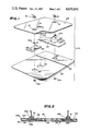
- FIG. 1 is an exploded perspective view of the various components used in an exemplary embodiment of the adhesively applied multi-element electrode of this invention
- FIG. 2 is a cross-sectional view of the assembled electrode of FIG. 1;
- FIGS. 3 and 4 are perspective and cross-sectional views of the FIGS. 1 and 2 embodiment in place with the external body surface of a living subject;
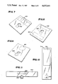
- FIGS. 5-9 are perspective views of other exemplary embodiments of the invention.
- FIGS. 10 and 11 are plan views of two further exemplary embodiments of the electrode structure.
- This invention relates to multiple element electrodes that have predetermined relative sizes and locations relative to an aperture in a common substrate which is applied as a single unit, with the aperture conveniently being used to (1) properly locate the electrodes vis-a-vis the desired treatment site and (2) provide access to the treatment site after affixation of the electrode structure.
- the electrode elements are constructed of a metal foil or film such as aluminum or a conductive film such as silver paint or carbon compound paint. These elements are affixed to an adhesive coated, thin, clear film such as pvc or mylar or are screened on a thin, clear film with adhesive selectively screened on at the same time.
- the multi-element electrode is produced with an opening or treatment site window to identify correct placement of the multi-electrode unit over the wound or injury.
- a release liner is provided on the back of the electrode.
- a two element example of this multi-element electrode that is useful for treating small skin wounds or burns is shown in FIG. 1.
- a monophasic or asymmetrical wave may be conventionally applied across the two elements correctly by use of different size electrical connectors or snaps that mate with the corresponding wires from a stimulator.
- An important feature of this invention is that one element, identified as the treatment electrode, is maintained at a fixed and optimum distance from the other remote electrode element(s) and at the same time is maintained at a close, but fixed optimum distance from the injury by means of properly locating the treatment site window over the treatment site. Also typically important in such situations is the fact that the surface area of the treatment electrode may be smaller than the surface area of the remote electrode(s) and that a fixed size ratio and relative location is maintained between electrode elements by use of this multi-element electrode. The current density at the injury or treatment site is maintained at a correct higher therapeutic level while the current density under the remote electrode(s) is lower due to the larger surface area of the remote electrode(s).
- the resulting current density (e.g., amperes per square centimeter) is a function of I/A.
- the current density can be increased by making the electrode of smaller size or, vice versa, it can be decreased by making the electrode of larger size.
- the distance of a given tissue mass from an electrode and its relative location with respect to the anode-cathode current path) will also affect the actual current density through the tissue mass (e.g., a wound). In this fashion, the relative sizes and placements of anode and cathode electrodes can be used to determine the effective current density through a wound.
- an electrode 103 of relatively large area as shown in FIG. 1 is utilized as an anode while a relatively smaller electrode 102 is applied relatively closer to a desired treatment site marker hole 116 (so as to provide an increased physiologically significant electrical current density thereabout) as a cathode electrode, and connected to the signal source (not shown) by lead wire 50. Electrical signals are then conventionally applied to the electrodes so as to achieve desired treatment effects.
- the smaller electrode 102 is the anode, and thus the electrode 103 is the cathode.
- some signal sources e.g. transcutaneous nerve stimulators (TENS), supply biphasic signals to the electrodes, i.e. alternating current or waveforms with both positive and negative components.
- TENS transcutaneous nerve stimulators
- the present invention can be used with a biphasic signal having the smaller electrode 102 relatively close to the treatment site and the larger electrode 103 at a more remote location. This arrangement insures a higher density at the treatment site and a lower, non-biologically stimulative, signal at the larger electrode 103.
- Multi-element electrode 100 is shown in detail at FIGS. 1 and 2.
- Conductive metal foils 102 and 103 constitute the active electrode surfaces.
- foils 102 and 103 are each actually a very thin (e.g., 0.00035 inch) layer of aluminum foil pre-laminated to a very thin (e.g., 0.00092) layer of polyester film (laminated to the top of structure 102 as seen in FIG.
- the laminated aluminum foil/polyester films 102 and 103 may be cut from commerically available material (e.g. part No. 1035 from Lam-A-Shield Incorporated, Cleveland, Ohio).
- the presently preferred adhesive-backed patch 104 is also cut from commerically available material (e.g. part No. 7350 from 3M Corporation which comprises a thin (e.g., 0.002 inch) insulating sheet of polypropylene with a thin (e.g., 0.0008 inch) coating of acrylic adhesive 104 on one side).
- a conventional snap-on type electrical connector comprising mated parts 106a and 106b is attached to a folded-over tab portion 108 of the laminated aluminum foil structure 102. Similar parts 107a and 107b are attached to the fold-over tab portion 109 of foil 103. Since it is folded over (as indicated by arrow 110), a conductive aluminum foil surface is exposed on both the top and bottom of the thus double thickness tab portions 108 and 109 for increased structural support and electrical area connection with the snap-on devices 106a and 106b and 107a and 107b.
- the snap-on connector parts have a connector projection which extends backwardly (i.e. upwardly in FIG. 1) through apertures 112 and 113 respectively in the insulating patch 104 so as to be readily available for snap-on electrical connection to lead wires 50 and 51.
- the flexible electrode assembly of FIGS. 1-2 also includes a releasable liner layer 122 which is normally in place covering the otherwise exposed portions of the adhesive surface 104a until the intended time of usage.
- the release liner 122 will include a break 124 so that the entire assembly may be slightly bent at the break to gain finger access to a free edge of the releasable liner 122 and thus facilitate its strippage from the adhesive layer 104a and ready the assembly for adhesive affixation to the desired body surface area.
- Release liner 122 is shown as including apertures 126, 128 and 129. Apertures 128 and 129 typically occurs because the liner 122 already may be in place when aperture 116 is cut during manufacturing processes and apertures 128 and 129 permit the assembly of snap-on connectors while the release liner 122 remains in place thus protecting the adhesive layer 104a during manufacturing processes. However it will be appreciated that such apertures are not required since the release liner 122 is typically removed before the remainder of the electrode assembly shown in FIGS. 1-2 is adhesively affixed to a desired body surface site and used.
- FIG. 3 depicts the electrodes of FIGS. 1-2 with the releasable liner 122 removed and the remainder of the assembly adhesively secured in place to a desired external body surface 20a of a living subject.
- the treatment site 20a should be clean and the connector end of cables 50 and 51 may be snapped onto the snap connectors 106a and 107a to installation of the electrode patches onto the treatment site.
- the protective releasable liner 122 has been removed so as to expose a boundary 130 of adhesive 104a, the assembly is positioned with the treatment aperture 116 over the injury site 20b and pressed firmly thereto so as to assure a good adhesive bond. As shown in the cross-sectional view of FIG.
- the boundary areas 130 will include an adhesively sealed and occluded area 130a which incorporates any contiguous body hair (or fur) so as to provide a substantially impervious seal between the external surface of living body 20 and the periphery of the conductive electrodes 102 and 103.
- an electrode patch e.g. 203 can have an aperture 114 extending therethrough for receiving an electrode gel preparation material in the space located between the electrode patch and the skin surface, after the electrode patch is adhesively affixed to the skin.
- the present invention may incorporate more than two electrodes, that is a treatment electrode and multiple remote electrodes (see FIGS. 6-8). Further, the electrodes may be arranged in a variety of ways and may be of various shapes and sizes. (see FIGS. 6-9). As shown in FIGS. 6-11, electrodes are denoted by numerals 302, 303; 402, 403; 502, 503; 602, 603; 702, 703; and 802, 803.
- the flexible insulating substrate is generally shown by the out or most boundary lines and is denoted by reference numerals 704 and 804 in FIGS. 10 and 11 respectively.
- FIG. 11 depicts an alternate embodiment without a continuous adhesive border.
- each conductive patch may also be formed by printing, painting or otherwise placing conductive ink on a suitable substrate.
- aluminum foil is preferred (e.g., it is conceivable that the ions which make an ink conductive might, over time, migrate under influence of the electrical treatment fields away from the printed ink itself thus deteriorating the overall electrode function).
- the conductive patch 103 may be approximately 3 inches by 1 inch and the treatment electrode 102 about one inch square, while the insulating patch 104 may be approximately 5 ⁇ 51/2 inches in overall dimension.
- Aperture 116 in the embodiment of FIGS. 1-2 may be approximately 0.688 inch diameter.
- electrode apparatus and method described may also be utilized to achieve conductive coupling to the external skin surfaces of human subjects as well as animals.
Abstract
Description
Claims (10)
Priority Applications (1)
| Application Number | Priority Date | Filing Date | Title |
|---|---|---|---|
| US06/788,215 US4635641A (en) | 1985-10-16 | 1985-10-16 | Multi-element electrode |
Applications Claiming Priority (1)
| Application Number | Priority Date | Filing Date | Title |
|---|---|---|---|
| US06/788,215 US4635641A (en) | 1985-10-16 | 1985-10-16 | Multi-element electrode |
Publications (1)
| Publication Number | Publication Date |
|---|---|
| US4635641A true US4635641A (en) | 1987-01-13 |
Family
ID=25143801
Family Applications (1)
| Application Number | Title | Priority Date | Filing Date |
|---|---|---|---|
| US06/788,215 Expired - Lifetime US4635641A (en) | 1985-10-16 | 1985-10-16 | Multi-element electrode |
Country Status (1)
| Country | Link |
|---|---|
| US (1) | US4635641A (en) |
Cited By (94)
| Publication number | Priority date | Publication date | Assignee | Title |
|---|---|---|---|---|
| US4787390A (en) * | 1987-04-15 | 1988-11-29 | Scovill Japan Kabushiki Kaisha | Electrode sensor |
| US4865038A (en) * | 1986-10-09 | 1989-09-12 | Novametrix Medical Systems, Inc. | Sensor appliance for non-invasive monitoring |
| US5046511A (en) * | 1989-11-28 | 1991-09-10 | Empi, Inc. | Vaginal electrode with snap-on electrode pad and method for preparing electrode for use |
| US5254081A (en) * | 1991-02-01 | 1993-10-19 | Empi, Inc. | Multiple site drug iontophoresis electronic device and method |
| WO1994015527A1 (en) * | 1993-01-11 | 1994-07-21 | Jens Axelgaard | Medical electrode system |
| WO1994017853A1 (en) * | 1993-02-02 | 1994-08-18 | Becton Dickinson And Company | Active drug delivery device, electrode, and method for making same |
| FR2739015A1 (en) * | 1995-09-26 | 1997-03-28 | Prothia Sarl | Nerve stimulation with relocatable electrodes |
| US5645063A (en) * | 1995-06-05 | 1997-07-08 | Quinton Instrument Company | Skin electrode having multiple conductive center members |
| FR2746018A1 (en) * | 1996-03-15 | 1997-09-19 | Bmr Res & Dev Ltd | ELECTRODE ASSEMBLY AND METHOD FOR MANUFACTURING THE SAME |
| US6148233A (en) * | 1997-03-07 | 2000-11-14 | Cardiac Science, Inc. | Defibrillation system having segmented electrodes |
| US6564079B1 (en) | 2000-07-27 | 2003-05-13 | Ckm Diagnostics, Inc. | Electrode array and skin attachment system for noninvasive nerve location and imaging device |
| US6782283B2 (en) | 2001-09-07 | 2004-08-24 | Robert N. Schmidt | Dry penetrating recording device |
| US6785569B2 (en) | 2001-09-07 | 2004-08-31 | Orbital Research | Dry physiological recording electrode |
| US20060173523A1 (en) * | 2005-02-01 | 2006-08-03 | Rainey Christopher J | Electrode arrangement for applying electrical signals to the skin of an animal |
| WO2006082384A2 (en) * | 2005-02-01 | 2006-08-10 | Wound Solutions Limited | Electrode arrangement for applying electrical signals to the skin of an animal |
| US20070163874A1 (en) * | 2001-01-17 | 2007-07-19 | Zuppero Anthony C | Electron-Jump Chemical Energy Converter |
| US7286864B1 (en) | 2001-09-07 | 2007-10-23 | Orbital Research, Inc. | Dry physiological recording device |
| US20080161884A1 (en) * | 2004-12-23 | 2008-07-03 | Mark Chandler | Method and apparatus for treating or preventing a medical condition |
| US20080306360A1 (en) * | 2007-05-24 | 2008-12-11 | Robertson Timothy L | Low profile antenna for in body device |
| US20090076338A1 (en) * | 2006-05-02 | 2009-03-19 | Zdeblick Mark J | Patient customized therapeutic regimens |
| US20090082645A1 (en) * | 2007-09-25 | 2009-03-26 | Proteus Biomedical, Inc. | In-body device with virtual dipole signal amplification |
| US20090135886A1 (en) * | 2007-11-27 | 2009-05-28 | Proteus Biomedical, Inc. | Transbody communication systems employing communication channels |
| US20090227204A1 (en) * | 2005-04-28 | 2009-09-10 | Timothy Robertson | Pharma-Informatics System |
| JP2010500076A (en) * | 2006-08-07 | 2010-01-07 | コーニンクレッカ フィリップス エレクトロニクス エヌ ヴィ | Plaster and radiation system |
| US20100022836A1 (en) * | 2007-03-09 | 2010-01-28 | Olivier Colliou | In-body device having a multi-directional transmitter |
| US20100185055A1 (en) * | 2007-02-01 | 2010-07-22 | Timothy Robertson | Ingestible event marker systems |
| US20100312188A1 (en) * | 2008-12-15 | 2010-12-09 | Timothy Robertson | Body-Associated Receiver and Method |
| US20100316158A1 (en) * | 2006-11-20 | 2010-12-16 | Lawrence Arne | Active signal processing personal health signal receivers |
| US20100318018A1 (en) * | 2007-05-25 | 2010-12-16 | Klaus Schonenberger | Wound healing electrode set |
| US20110054265A1 (en) * | 2009-04-28 | 2011-03-03 | Hooman Hafezi | Highly reliable ingestible event markers and methods for using the same |
| US20110065983A1 (en) * | 2008-08-13 | 2011-03-17 | Hooman Hafezi | Ingestible Circuitry |
| US20110196454A1 (en) * | 2008-11-18 | 2011-08-11 | Proteus Biomedical, Inc. | Sensing system, device, and method for therapy modulation |
| US20110196220A1 (en) * | 2008-10-22 | 2011-08-11 | Med Storm Innovation As | Electrode Assembly for Medical Purposes |
| US20110212782A1 (en) * | 2008-10-14 | 2011-09-01 | Andrew Thompson | Method and System for Incorporating Physiologic Data in a Gaming Environment |
| US8036748B2 (en) | 2008-11-13 | 2011-10-11 | Proteus Biomedical, Inc. | Ingestible therapy activator system and method |
| US8054140B2 (en) | 2006-10-17 | 2011-11-08 | Proteus Biomedical, Inc. | Low voltage oscillator for medical devices |
| US8055334B2 (en) | 2008-12-11 | 2011-11-08 | Proteus Biomedical, Inc. | Evaluation of gastrointestinal function using portable electroviscerography systems and methods of using the same |
| US8258962B2 (en) | 2008-03-05 | 2012-09-04 | Proteus Biomedical, Inc. | Multi-mode communication ingestible event markers and systems, and methods of using the same |
| US8540664B2 (en) | 2009-03-25 | 2013-09-24 | Proteus Digital Health, Inc. | Probablistic pharmacokinetic and pharmacodynamic modeling |
| US8547248B2 (en) | 2005-09-01 | 2013-10-01 | Proteus Digital Health, Inc. | Implantable zero-wire communications system |
| US8558563B2 (en) | 2009-08-21 | 2013-10-15 | Proteus Digital Health, Inc. | Apparatus and method for measuring biochemical parameters |
| US8597186B2 (en) | 2009-01-06 | 2013-12-03 | Proteus Digital Health, Inc. | Pharmaceutical dosages delivery system |
| US8730031B2 (en) | 2005-04-28 | 2014-05-20 | Proteus Digital Health, Inc. | Communication system using an implantable device |
| WO2014102896A1 (en) * | 2012-12-25 | 2014-07-03 | テルモ株式会社 | Iontophoresis patch |
| US20140188200A1 (en) * | 2009-10-05 | 2014-07-03 | The Regents Of The University Of California | Systems, devices and methods for the treatment of neurological disorders and conditions |
| US8784308B2 (en) | 2009-12-02 | 2014-07-22 | Proteus Digital Health, Inc. | Integrated ingestible event marker system with pharmaceutical product |
| US8802183B2 (en) | 2005-04-28 | 2014-08-12 | Proteus Digital Health, Inc. | Communication system with enhanced partial power source and method of manufacturing same |
| US8836513B2 (en) | 2006-04-28 | 2014-09-16 | Proteus Digital Health, Inc. | Communication system incorporated in an ingestible product |
| US8868453B2 (en) | 2009-11-04 | 2014-10-21 | Proteus Digital Health, Inc. | System for supply chain management |
| US8912908B2 (en) | 2005-04-28 | 2014-12-16 | Proteus Digital Health, Inc. | Communication system with remote activation |
| US8945005B2 (en) | 2006-10-25 | 2015-02-03 | Proteus Digital Health, Inc. | Controlled activation ingestible identifier |
| US8956288B2 (en) | 2007-02-14 | 2015-02-17 | Proteus Digital Health, Inc. | In-body power source having high surface area electrode |
| US9014779B2 (en) | 2010-02-01 | 2015-04-21 | Proteus Digital Health, Inc. | Data gathering system |
| WO2015079448A1 (en) * | 2013-12-01 | 2015-06-04 | Cardiologic Innovations Ltd | A patient monitoring system |
| US9107806B2 (en) | 2010-11-22 | 2015-08-18 | Proteus Digital Health, Inc. | Ingestible device with pharmaceutical product |
| US9149423B2 (en) | 2009-05-12 | 2015-10-06 | Proteus Digital Health, Inc. | Ingestible event markers comprising an ingestible component |
| US9192313B1 (en) | 2013-03-14 | 2015-11-24 | Orbital Research Inc. | Dry physiological recording device and method of manufacturing |
| US9198608B2 (en) | 2005-04-28 | 2015-12-01 | Proteus Digital Health, Inc. | Communication system incorporated in a container |
| US9235683B2 (en) | 2011-11-09 | 2016-01-12 | Proteus Digital Health, Inc. | Apparatus, system, and method for managing adherence to a regimen |
| US9270025B2 (en) | 2007-03-09 | 2016-02-23 | Proteus Digital Health, Inc. | In-body device having deployable antenna |
| US9268909B2 (en) | 2012-10-18 | 2016-02-23 | Proteus Digital Health, Inc. | Apparatus, system, and method to adaptively optimize power dissipation and broadcast power in a power source for a communication device |
| US9270503B2 (en) | 2013-09-20 | 2016-02-23 | Proteus Digital Health, Inc. | Methods, devices and systems for receiving and decoding a signal in the presence of noise using slices and warping |
| US9271897B2 (en) | 2012-07-23 | 2016-03-01 | Proteus Digital Health, Inc. | Techniques for manufacturing ingestible event markers comprising an ingestible component |
| WO2016044341A1 (en) * | 2014-09-16 | 2016-03-24 | Enermed, Llc | A wound care bandage and method of wound healing |
| US9364674B2 (en) | 2010-11-30 | 2016-06-14 | Ian A. Cook | Pulse generator for cranial nerve stimulation |
| US9439566B2 (en) | 2008-12-15 | 2016-09-13 | Proteus Digital Health, Inc. | Re-wearable wireless device |
| US9439599B2 (en) | 2011-03-11 | 2016-09-13 | Proteus Digital Health, Inc. | Wearable personal body associated device with various physical configurations |
| US20160367434A1 (en) * | 2015-06-17 | 2016-12-22 | Mimi Gruber | Electroacupuncture enhanced acupressure treatment apparatus and associated electrode assembly |
| US9577864B2 (en) | 2013-09-24 | 2017-02-21 | Proteus Digital Health, Inc. | Method and apparatus for use with received electromagnetic signal at a frequency not known exactly in advance |
| US9597487B2 (en) | 2010-04-07 | 2017-03-21 | Proteus Digital Health, Inc. | Miniature ingestible device |
| US9603550B2 (en) | 2008-07-08 | 2017-03-28 | Proteus Digital Health, Inc. | State characterization based on multi-variate data fusion techniques |
| US9659423B2 (en) | 2008-12-15 | 2017-05-23 | Proteus Digital Health, Inc. | Personal authentication apparatus system and method |
| US9756874B2 (en) | 2011-07-11 | 2017-09-12 | Proteus Digital Health, Inc. | Masticable ingestible product and communication system therefor |
| US9796576B2 (en) | 2013-08-30 | 2017-10-24 | Proteus Digital Health, Inc. | Container with electronically controlled interlock |
| EP3131622A4 (en) * | 2014-04-14 | 2017-12-20 | Elidah, Inc. | Device to treat incontinence |
| US9883819B2 (en) | 2009-01-06 | 2018-02-06 | Proteus Digital Health, Inc. | Ingestion-related biofeedback and personalized medical therapy method and system |
| US10035016B2 (en) | 2014-04-14 | 2018-07-31 | Elidah, Inc. | Electrical stimulation device |
| US10084880B2 (en) | 2013-11-04 | 2018-09-25 | Proteus Digital Health, Inc. | Social media networking based on physiologic information |
| US10175376B2 (en) | 2013-03-15 | 2019-01-08 | Proteus Digital Health, Inc. | Metal detector apparatus, system, and method |
| US10187121B2 (en) | 2016-07-22 | 2019-01-22 | Proteus Digital Health, Inc. | Electromagnetic sensing and detection of ingestible event markers |
| US10223905B2 (en) | 2011-07-21 | 2019-03-05 | Proteus Digital Health, Inc. | Mobile device and system for detection and communication of information received from an ingestible device |
| US10238862B2 (en) | 2009-10-05 | 2019-03-26 | The Regents Of The University Of California | Extracranial implantable devices, systems and methods for the treatment of medical disorders |
| US20190091466A1 (en) * | 2016-03-01 | 2019-03-28 | Vomaris Innovations, Inc. | Bioelectric devices for use on specific areas of the body |
| US10398161B2 (en) | 2014-01-21 | 2019-09-03 | Proteus Digital Heal Th, Inc. | Masticable ingestible product and communication system therefor |
| US10529044B2 (en) | 2010-05-19 | 2020-01-07 | Proteus Digital Health, Inc. | Tracking and delivery confirmation of pharmaceutical products |
| US10639468B2 (en) | 2009-10-05 | 2020-05-05 | The Regents Of The University Of California | Devices, systems and methods for the treatment of medical disorders |
| WO2021065580A1 (en) * | 2019-10-04 | 2021-04-08 | Nihon Kohden Corporation | Body electrode unit |
| US11051543B2 (en) | 2015-07-21 | 2021-07-06 | Otsuka Pharmaceutical Co. Ltd. | Alginate on adhesive bilayer laminate film |
| US11149123B2 (en) | 2013-01-29 | 2021-10-19 | Otsuka Pharmaceutical Co., Ltd. | Highly-swellable polymeric films and compositions comprising the same |
| US11158149B2 (en) | 2013-03-15 | 2021-10-26 | Otsuka Pharmaceutical Co., Ltd. | Personal authentication apparatus system and method |
| US11529071B2 (en) | 2016-10-26 | 2022-12-20 | Otsuka Pharmaceutical Co., Ltd. | Methods for manufacturing capsules with ingestible event markers |
| WO2023111863A1 (en) * | 2021-12-14 | 2023-06-22 | Novocure Gmbh | Transducer array with shape that contours to a subject's body and method of determining shape and placement of transducer arrays |
| WO2023111847A1 (en) * | 2021-12-14 | 2023-06-22 | Novocure Gmbh | Transducer array with adhesive layer shaped to reduce skin irritation |
| US11744481B2 (en) | 2013-03-15 | 2023-09-05 | Otsuka Pharmaceutical Co., Ltd. | System, apparatus and methods for data collection and assessing outcomes |
Citations (8)
| Publication number | Priority date | Publication date | Assignee | Title |
|---|---|---|---|---|
| US2555037A (en) * | 1949-06-21 | 1951-05-29 | Jensen Lee | Flexible electrode |
| US3122137A (en) * | 1961-10-30 | 1964-02-25 | Erlanger Gustav | Device for facilitating iontophoresis treatment of eyes |
| US3746004A (en) * | 1971-06-14 | 1973-07-17 | B Jankelson | Disposable electrodes for electrical stimulation of muscles and nerves of the head |
| US3848600A (en) * | 1972-02-03 | 1974-11-19 | Ndm Corp | Indifferent electrode in electrosurgical procedures and method of use |
| US4062364A (en) * | 1975-01-21 | 1977-12-13 | Kazumi Masaki | Electrode for use in low frequency electronic therapy device |
| US4082086A (en) * | 1976-12-13 | 1978-04-04 | M I Systems, Inc. | Ecg monitoring pad |
| US4367755A (en) * | 1979-01-31 | 1983-01-11 | Stimtech, Inc. | Stimulating electrode |
| US4524087A (en) * | 1980-01-23 | 1985-06-18 | Minnesota Mining And Manufacturing Company | Conductive adhesive and biomedical electrode |
-
1985
- 1985-10-16 US US06/788,215 patent/US4635641A/en not_active Expired - Lifetime
Patent Citations (9)
| Publication number | Priority date | Publication date | Assignee | Title |
|---|---|---|---|---|
| US2555037A (en) * | 1949-06-21 | 1951-05-29 | Jensen Lee | Flexible electrode |
| US3122137A (en) * | 1961-10-30 | 1964-02-25 | Erlanger Gustav | Device for facilitating iontophoresis treatment of eyes |
| US3746004A (en) * | 1971-06-14 | 1973-07-17 | B Jankelson | Disposable electrodes for electrical stimulation of muscles and nerves of the head |
| US3848600A (en) * | 1972-02-03 | 1974-11-19 | Ndm Corp | Indifferent electrode in electrosurgical procedures and method of use |
| US3848600B1 (en) * | 1972-02-03 | 1988-06-21 | ||
| US4062364A (en) * | 1975-01-21 | 1977-12-13 | Kazumi Masaki | Electrode for use in low frequency electronic therapy device |
| US4082086A (en) * | 1976-12-13 | 1978-04-04 | M I Systems, Inc. | Ecg monitoring pad |
| US4367755A (en) * | 1979-01-31 | 1983-01-11 | Stimtech, Inc. | Stimulating electrode |
| US4524087A (en) * | 1980-01-23 | 1985-06-18 | Minnesota Mining And Manufacturing Company | Conductive adhesive and biomedical electrode |
Cited By (188)
| Publication number | Priority date | Publication date | Assignee | Title |
|---|---|---|---|---|
| US4865038A (en) * | 1986-10-09 | 1989-09-12 | Novametrix Medical Systems, Inc. | Sensor appliance for non-invasive monitoring |
| US4787390A (en) * | 1987-04-15 | 1988-11-29 | Scovill Japan Kabushiki Kaisha | Electrode sensor |
| US5046511A (en) * | 1989-11-28 | 1991-09-10 | Empi, Inc. | Vaginal electrode with snap-on electrode pad and method for preparing electrode for use |
| US5254081A (en) * | 1991-02-01 | 1993-10-19 | Empi, Inc. | Multiple site drug iontophoresis electronic device and method |
| US5450845A (en) * | 1993-01-11 | 1995-09-19 | Axelgaard; Jens | Medical electrode system |
| WO1994015527A1 (en) * | 1993-01-11 | 1994-07-21 | Jens Axelgaard | Medical electrode system |
| US5785040A (en) * | 1993-01-11 | 1998-07-28 | Axelgaard; Jens | Medical electrode system |
| WO1994017853A1 (en) * | 1993-02-02 | 1994-08-18 | Becton Dickinson And Company | Active drug delivery device, electrode, and method for making same |
| US5645063A (en) * | 1995-06-05 | 1997-07-08 | Quinton Instrument Company | Skin electrode having multiple conductive center members |
| FR2739015A1 (en) * | 1995-09-26 | 1997-03-28 | Prothia Sarl | Nerve stimulation with relocatable electrodes |
| FR2746018A1 (en) * | 1996-03-15 | 1997-09-19 | Bmr Res & Dev Ltd | ELECTRODE ASSEMBLY AND METHOD FOR MANUFACTURING THE SAME |
| US6148233A (en) * | 1997-03-07 | 2000-11-14 | Cardiac Science, Inc. | Defibrillation system having segmented electrodes |
| US6546285B1 (en) | 1997-03-07 | 2003-04-08 | Cardiac Science, Inc. | Long term wear electrode for defibrillation system |
| US9089718B2 (en) | 1997-03-07 | 2015-07-28 | Cardiac Science Corporation | Defibrillation system |
| US6609018B2 (en) | 2000-07-27 | 2003-08-19 | Ckm Diagnostics, Inc. | Electrode array and sensor attachment system for noninvasive nerve location and imaging device |
| US6564079B1 (en) | 2000-07-27 | 2003-05-13 | Ckm Diagnostics, Inc. | Electrode array and skin attachment system for noninvasive nerve location and imaging device |
| US20070163874A1 (en) * | 2001-01-17 | 2007-07-19 | Zuppero Anthony C | Electron-Jump Chemical Energy Converter |
| US7286864B1 (en) | 2001-09-07 | 2007-10-23 | Orbital Research, Inc. | Dry physiological recording device |
| US6785569B2 (en) | 2001-09-07 | 2004-08-31 | Orbital Research | Dry physiological recording electrode |
| US7032301B1 (en) | 2001-09-07 | 2006-04-25 | Orbital Research Inc | Dry physiological recording electrode |
| US7032302B1 (en) | 2001-09-07 | 2006-04-25 | Orbital Research Inc. | Dry physiological recording device |
| US7489959B1 (en) | 2001-09-07 | 2009-02-10 | Orbital Research Inc. | Physiological recording device |
| US6782283B2 (en) | 2001-09-07 | 2004-08-24 | Robert N. Schmidt | Dry penetrating recording device |
| US20080161884A1 (en) * | 2004-12-23 | 2008-07-03 | Mark Chandler | Method and apparatus for treating or preventing a medical condition |
| WO2006082384A3 (en) * | 2005-02-01 | 2006-12-21 | Wound Solutions Ltd | Electrode arrangement for applying electrical signals to the skin of an animal |
| AU2006210702B2 (en) * | 2005-02-01 | 2012-07-26 | Oxford Bioelectronics Limited | Electrode arrangement for applying electrical signals to the skin of an animal |
| WO2006082384A2 (en) * | 2005-02-01 | 2006-08-10 | Wound Solutions Limited | Electrode arrangement for applying electrical signals to the skin of an animal |
| US7742829B2 (en) | 2005-02-01 | 2010-06-22 | Wound Solutions Limited | Electrode arrangement for applying electrical signals to the skin of an animal |
| US20060173523A1 (en) * | 2005-02-01 | 2006-08-03 | Rainey Christopher J | Electrode arrangement for applying electrical signals to the skin of an animal |
| US9439582B2 (en) | 2005-04-28 | 2016-09-13 | Proteus Digital Health, Inc. | Communication system with remote activation |
| US9681842B2 (en) | 2005-04-28 | 2017-06-20 | Proteus Digital Health, Inc. | Pharma-informatics system |
| US10610128B2 (en) | 2005-04-28 | 2020-04-07 | Proteus Digital Health, Inc. | Pharma-informatics system |
| US9597010B2 (en) | 2005-04-28 | 2017-03-21 | Proteus Digital Health, Inc. | Communication system using an implantable device |
| US20100081894A1 (en) * | 2005-04-28 | 2010-04-01 | Proteus Biomedical, Inc. | Communication system with partial power source |
| US9198608B2 (en) | 2005-04-28 | 2015-12-01 | Proteus Digital Health, Inc. | Communication system incorporated in a container |
| US9119554B2 (en) | 2005-04-28 | 2015-09-01 | Proteus Digital Health, Inc. | Pharma-informatics system |
| US10542909B2 (en) | 2005-04-28 | 2020-01-28 | Proteus Digital Health, Inc. | Communication system with partial power source |
| US9649066B2 (en) | 2005-04-28 | 2017-05-16 | Proteus Digital Health, Inc. | Communication system with partial power source |
| US9161707B2 (en) | 2005-04-28 | 2015-10-20 | Proteus Digital Health, Inc. | Communication system incorporated in an ingestible product |
| US11476952B2 (en) | 2005-04-28 | 2022-10-18 | Otsuka Pharmaceutical Co., Ltd. | Pharma-informatics system |
| US8802183B2 (en) | 2005-04-28 | 2014-08-12 | Proteus Digital Health, Inc. | Communication system with enhanced partial power source and method of manufacturing same |
| US7978064B2 (en) | 2005-04-28 | 2011-07-12 | Proteus Biomedical, Inc. | Communication system with partial power source |
| US9962107B2 (en) | 2005-04-28 | 2018-05-08 | Proteus Digital Health, Inc. | Communication system with enhanced partial power source and method of manufacturing same |
| US8674825B2 (en) | 2005-04-28 | 2014-03-18 | Proteus Digital Health, Inc. | Pharma-informatics system |
| US8912908B2 (en) | 2005-04-28 | 2014-12-16 | Proteus Digital Health, Inc. | Communication system with remote activation |
| US8847766B2 (en) | 2005-04-28 | 2014-09-30 | Proteus Digital Health, Inc. | Pharma-informatics system |
| US8730031B2 (en) | 2005-04-28 | 2014-05-20 | Proteus Digital Health, Inc. | Communication system using an implantable device |
| US10517507B2 (en) | 2005-04-28 | 2019-12-31 | Proteus Digital Health, Inc. | Communication system with enhanced partial power source and method of manufacturing same |
| US20090227204A1 (en) * | 2005-04-28 | 2009-09-10 | Timothy Robertson | Pharma-Informatics System |
| US8816847B2 (en) | 2005-04-28 | 2014-08-26 | Proteus Digital Health, Inc. | Communication system with partial power source |
| US8547248B2 (en) | 2005-09-01 | 2013-10-01 | Proteus Digital Health, Inc. | Implantable zero-wire communications system |
| US8836513B2 (en) | 2006-04-28 | 2014-09-16 | Proteus Digital Health, Inc. | Communication system incorporated in an ingestible product |
| US20090076338A1 (en) * | 2006-05-02 | 2009-03-19 | Zdeblick Mark J | Patient customized therapeutic regimens |
| US8956287B2 (en) | 2006-05-02 | 2015-02-17 | Proteus Digital Health, Inc. | Patient customized therapeutic regimens |
| US11928614B2 (en) | 2006-05-02 | 2024-03-12 | Otsuka Pharmaceutical Co., Ltd. | Patient customized therapeutic regimens |
| JP2010500076A (en) * | 2006-08-07 | 2010-01-07 | コーニンクレッカ フィリップス エレクトロニクス エヌ ヴィ | Plaster and radiation system |
| US8054140B2 (en) | 2006-10-17 | 2011-11-08 | Proteus Biomedical, Inc. | Low voltage oscillator for medical devices |
| US10238604B2 (en) | 2006-10-25 | 2019-03-26 | Proteus Digital Health, Inc. | Controlled activation ingestible identifier |
| US11357730B2 (en) | 2006-10-25 | 2022-06-14 | Otsuka Pharmaceutical Co., Ltd. | Controlled activation ingestible identifier |
| US8945005B2 (en) | 2006-10-25 | 2015-02-03 | Proteus Digital Health, Inc. | Controlled activation ingestible identifier |
| US20100316158A1 (en) * | 2006-11-20 | 2010-12-16 | Lawrence Arne | Active signal processing personal health signal receivers |
| US9083589B2 (en) | 2006-11-20 | 2015-07-14 | Proteus Digital Health, Inc. | Active signal processing personal health signal receivers |
| US8718193B2 (en) | 2006-11-20 | 2014-05-06 | Proteus Digital Health, Inc. | Active signal processing personal health signal receivers |
| US9444503B2 (en) | 2006-11-20 | 2016-09-13 | Proteus Digital Health, Inc. | Active signal processing personal health signal receivers |
| US8858432B2 (en) | 2007-02-01 | 2014-10-14 | Proteus Digital Health, Inc. | Ingestible event marker systems |
| US20100185055A1 (en) * | 2007-02-01 | 2010-07-22 | Timothy Robertson | Ingestible event marker systems |
| US10441194B2 (en) | 2007-02-01 | 2019-10-15 | Proteus Digital Heal Th, Inc. | Ingestible event marker systems |
| US11464423B2 (en) | 2007-02-14 | 2022-10-11 | Otsuka Pharmaceutical Co., Ltd. | In-body power source having high surface area electrode |
| US8956288B2 (en) | 2007-02-14 | 2015-02-17 | Proteus Digital Health, Inc. | In-body power source having high surface area electrode |
| US8932221B2 (en) | 2007-03-09 | 2015-01-13 | Proteus Digital Health, Inc. | In-body device having a multi-directional transmitter |
| US20100022836A1 (en) * | 2007-03-09 | 2010-01-28 | Olivier Colliou | In-body device having a multi-directional transmitter |
| US9270025B2 (en) | 2007-03-09 | 2016-02-23 | Proteus Digital Health, Inc. | In-body device having deployable antenna |
| US8115618B2 (en) | 2007-05-24 | 2012-02-14 | Proteus Biomedical, Inc. | RFID antenna for in-body device |
| US20080306360A1 (en) * | 2007-05-24 | 2008-12-11 | Robertson Timothy L | Low profile antenna for in body device |
| US10517506B2 (en) | 2007-05-24 | 2019-12-31 | Proteus Digital Health, Inc. | Low profile antenna for in body device |
| US8540632B2 (en) | 2007-05-24 | 2013-09-24 | Proteus Digital Health, Inc. | Low profile antenna for in body device |
| US11213672B2 (en) | 2007-05-25 | 2022-01-04 | Djo, Llc | Wound healing electrode set |
| US20100318018A1 (en) * | 2007-05-25 | 2010-12-16 | Klaus Schonenberger | Wound healing electrode set |
| US10130805B2 (en) | 2007-05-25 | 2018-11-20 | Empi, Inc. | Wound healing electrode set |
| US9174042B2 (en) | 2007-05-25 | 2015-11-03 | Empi, Inc. | Wound healing electrode set |
| US8961412B2 (en) | 2007-09-25 | 2015-02-24 | Proteus Digital Health, Inc. | In-body device with virtual dipole signal amplification |
| US9433371B2 (en) | 2007-09-25 | 2016-09-06 | Proteus Digital Health, Inc. | In-body device with virtual dipole signal amplification |
| US20090082645A1 (en) * | 2007-09-25 | 2009-03-26 | Proteus Biomedical, Inc. | In-body device with virtual dipole signal amplification |
| US20090135886A1 (en) * | 2007-11-27 | 2009-05-28 | Proteus Biomedical, Inc. | Transbody communication systems employing communication channels |
| US9060708B2 (en) | 2008-03-05 | 2015-06-23 | Proteus Digital Health, Inc. | Multi-mode communication ingestible event markers and systems, and methods of using the same |
| US9258035B2 (en) | 2008-03-05 | 2016-02-09 | Proteus Digital Health, Inc. | Multi-mode communication ingestible event markers and systems, and methods of using the same |
| US8258962B2 (en) | 2008-03-05 | 2012-09-04 | Proteus Biomedical, Inc. | Multi-mode communication ingestible event markers and systems, and methods of using the same |
| US8810409B2 (en) | 2008-03-05 | 2014-08-19 | Proteus Digital Health, Inc. | Multi-mode communication ingestible event markers and systems, and methods of using the same |
| US8542123B2 (en) | 2008-03-05 | 2013-09-24 | Proteus Digital Health, Inc. | Multi-mode communication ingestible event markers and systems, and methods of using the same |
| US10682071B2 (en) | 2008-07-08 | 2020-06-16 | Proteus Digital Health, Inc. | State characterization based on multi-variate data fusion techniques |
| US9603550B2 (en) | 2008-07-08 | 2017-03-28 | Proteus Digital Health, Inc. | State characterization based on multi-variate data fusion techniques |
| US11217342B2 (en) | 2008-07-08 | 2022-01-04 | Otsuka Pharmaceutical Co., Ltd. | Ingestible event marker data framework |
| US20110065983A1 (en) * | 2008-08-13 | 2011-03-17 | Hooman Hafezi | Ingestible Circuitry |
| US8721540B2 (en) | 2008-08-13 | 2014-05-13 | Proteus Digital Health, Inc. | Ingestible circuitry |
| US9415010B2 (en) | 2008-08-13 | 2016-08-16 | Proteus Digital Health, Inc. | Ingestible circuitry |
| US8540633B2 (en) | 2008-08-13 | 2013-09-24 | Proteus Digital Health, Inc. | Identifier circuits for generating unique identifiable indicators and techniques for producing same |
| US20110212782A1 (en) * | 2008-10-14 | 2011-09-01 | Andrew Thompson | Method and System for Incorporating Physiologic Data in a Gaming Environment |
| US20110196220A1 (en) * | 2008-10-22 | 2011-08-11 | Med Storm Innovation As | Electrode Assembly for Medical Purposes |
| US8036748B2 (en) | 2008-11-13 | 2011-10-11 | Proteus Biomedical, Inc. | Ingestible therapy activator system and method |
| US20110196454A1 (en) * | 2008-11-18 | 2011-08-11 | Proteus Biomedical, Inc. | Sensing system, device, and method for therapy modulation |
| US8055334B2 (en) | 2008-12-11 | 2011-11-08 | Proteus Biomedical, Inc. | Evaluation of gastrointestinal function using portable electroviscerography systems and methods of using the same |
| US8583227B2 (en) | 2008-12-11 | 2013-11-12 | Proteus Digital Health, Inc. | Evaluation of gastrointestinal function using portable electroviscerography systems and methods of using the same |
| US20100312188A1 (en) * | 2008-12-15 | 2010-12-09 | Timothy Robertson | Body-Associated Receiver and Method |
| US8114021B2 (en) | 2008-12-15 | 2012-02-14 | Proteus Biomedical, Inc. | Body-associated receiver and method |
| US9659423B2 (en) | 2008-12-15 | 2017-05-23 | Proteus Digital Health, Inc. | Personal authentication apparatus system and method |
| US9149577B2 (en) | 2008-12-15 | 2015-10-06 | Proteus Digital Health, Inc. | Body-associated receiver and method |
| US9439566B2 (en) | 2008-12-15 | 2016-09-13 | Proteus Digital Health, Inc. | Re-wearable wireless device |
| US8545436B2 (en) | 2008-12-15 | 2013-10-01 | Proteus Digital Health, Inc. | Body-associated receiver and method |
| US9883819B2 (en) | 2009-01-06 | 2018-02-06 | Proteus Digital Health, Inc. | Ingestion-related biofeedback and personalized medical therapy method and system |
| US8597186B2 (en) | 2009-01-06 | 2013-12-03 | Proteus Digital Health, Inc. | Pharmaceutical dosages delivery system |
| US8540664B2 (en) | 2009-03-25 | 2013-09-24 | Proteus Digital Health, Inc. | Probablistic pharmacokinetic and pharmacodynamic modeling |
| US9119918B2 (en) | 2009-03-25 | 2015-09-01 | Proteus Digital Health, Inc. | Probablistic pharmacokinetic and pharmacodynamic modeling |
| US10588544B2 (en) | 2009-04-28 | 2020-03-17 | Proteus Digital Health, Inc. | Highly reliable ingestible event markers and methods for using the same |
| US8545402B2 (en) | 2009-04-28 | 2013-10-01 | Proteus Digital Health, Inc. | Highly reliable ingestible event markers and methods for using the same |
| US20110054265A1 (en) * | 2009-04-28 | 2011-03-03 | Hooman Hafezi | Highly reliable ingestible event markers and methods for using the same |
| US9320455B2 (en) | 2009-04-28 | 2016-04-26 | Proteus Digital Health, Inc. | Highly reliable ingestible event markers and methods for using the same |
| US9149423B2 (en) | 2009-05-12 | 2015-10-06 | Proteus Digital Health, Inc. | Ingestible event markers comprising an ingestible component |
| US8558563B2 (en) | 2009-08-21 | 2013-10-15 | Proteus Digital Health, Inc. | Apparatus and method for measuring biochemical parameters |
| US10195435B2 (en) | 2009-10-05 | 2019-02-05 | The Regents Of The University Of California | Extracranial implantable devices, systems and methods for the treatment of neuropsychiatric disorders |
| US9511223B2 (en) | 2009-10-05 | 2016-12-06 | The Regents Of The University Of California | Extracranial implantable devices, systems and methods for the treatment of neuropsychiatric disorders |
| US10322283B2 (en) | 2009-10-05 | 2019-06-18 | The Regents Of The University Of California | Devices, systems and methods for treatment of neuropsychiatric disorders |
| US9238139B2 (en) | 2009-10-05 | 2016-01-19 | The Regents Of The University Of California | Devices, systems and methods for treatment of neuropsychiatric disorders |
| US8958880B2 (en) | 2009-10-05 | 2015-02-17 | The Regents Of The University Of California | Extracranial implantable devices, systems and methods for the treatment of neuropsychiatric disorders |
| US10639468B2 (en) | 2009-10-05 | 2020-05-05 | The Regents Of The University Of California | Devices, systems and methods for the treatment of medical disorders |
| US20140188200A1 (en) * | 2009-10-05 | 2014-07-03 | The Regents Of The University Of California | Systems, devices and methods for the treatment of neurological disorders and conditions |
| US10238862B2 (en) | 2009-10-05 | 2019-03-26 | The Regents Of The University Of California | Extracranial implantable devices, systems and methods for the treatment of medical disorders |
| US10058704B2 (en) | 2009-10-05 | 2018-08-28 | The Regents Of The University Of California | Systems, devices and methods for the treatment of neurological disorders and conditions |
| US9504827B2 (en) * | 2009-10-05 | 2016-11-29 | The Regents Of The University Of California | Systems, devices and methods for the treatment of neurological disorders and conditions |
| US9682236B2 (en) | 2009-10-05 | 2017-06-20 | The Regents Of The University Of California | Devices, systems and methods for treatment of neuropsychiatric disorders |
| US8868453B2 (en) | 2009-11-04 | 2014-10-21 | Proteus Digital Health, Inc. | System for supply chain management |
| US9941931B2 (en) | 2009-11-04 | 2018-04-10 | Proteus Digital Health, Inc. | System for supply chain management |
| US10305544B2 (en) | 2009-11-04 | 2019-05-28 | Proteus Digital Health, Inc. | System for supply chain management |
| US8784308B2 (en) | 2009-12-02 | 2014-07-22 | Proteus Digital Health, Inc. | Integrated ingestible event marker system with pharmaceutical product |
| US10376218B2 (en) | 2010-02-01 | 2019-08-13 | Proteus Digital Health, Inc. | Data gathering system |
| US9014779B2 (en) | 2010-02-01 | 2015-04-21 | Proteus Digital Health, Inc. | Data gathering system |
| US10207093B2 (en) | 2010-04-07 | 2019-02-19 | Proteus Digital Health, Inc. | Miniature ingestible device |
| US9597487B2 (en) | 2010-04-07 | 2017-03-21 | Proteus Digital Health, Inc. | Miniature ingestible device |
| US11173290B2 (en) | 2010-04-07 | 2021-11-16 | Otsuka Pharmaceutical Co., Ltd. | Miniature ingestible device |
| US10529044B2 (en) | 2010-05-19 | 2020-01-07 | Proteus Digital Health, Inc. | Tracking and delivery confirmation of pharmaceutical products |
| US11504511B2 (en) | 2010-11-22 | 2022-11-22 | Otsuka Pharmaceutical Co., Ltd. | Ingestible device with pharmaceutical product |
| US9107806B2 (en) | 2010-11-22 | 2015-08-18 | Proteus Digital Health, Inc. | Ingestible device with pharmaceutical product |
| US10016601B2 (en) | 2010-11-30 | 2018-07-10 | The Regents Of The University Of California | Pulse generator for cranial nerve stimulation |
| US9364674B2 (en) | 2010-11-30 | 2016-06-14 | Ian A. Cook | Pulse generator for cranial nerve stimulation |
| US9439599B2 (en) | 2011-03-11 | 2016-09-13 | Proteus Digital Health, Inc. | Wearable personal body associated device with various physical configurations |
| US11229378B2 (en) | 2011-07-11 | 2022-01-25 | Otsuka Pharmaceutical Co., Ltd. | Communication system with enhanced partial power source and method of manufacturing same |
| US9756874B2 (en) | 2011-07-11 | 2017-09-12 | Proteus Digital Health, Inc. | Masticable ingestible product and communication system therefor |
| US10223905B2 (en) | 2011-07-21 | 2019-03-05 | Proteus Digital Health, Inc. | Mobile device and system for detection and communication of information received from an ingestible device |
| US9235683B2 (en) | 2011-11-09 | 2016-01-12 | Proteus Digital Health, Inc. | Apparatus, system, and method for managing adherence to a regimen |
| US9271897B2 (en) | 2012-07-23 | 2016-03-01 | Proteus Digital Health, Inc. | Techniques for manufacturing ingestible event markers comprising an ingestible component |
| US9268909B2 (en) | 2012-10-18 | 2016-02-23 | Proteus Digital Health, Inc. | Apparatus, system, and method to adaptively optimize power dissipation and broadcast power in a power source for a communication device |
| JPWO2014102896A1 (en) * | 2012-12-25 | 2017-01-12 | テルモ株式会社 | Iontophoresis patch |
| WO2014102896A1 (en) * | 2012-12-25 | 2014-07-03 | テルモ株式会社 | Iontophoresis patch |
| US11149123B2 (en) | 2013-01-29 | 2021-10-19 | Otsuka Pharmaceutical Co., Ltd. | Highly-swellable polymeric films and compositions comprising the same |
| US9192313B1 (en) | 2013-03-14 | 2015-11-24 | Orbital Research Inc. | Dry physiological recording device and method of manufacturing |
| US11158149B2 (en) | 2013-03-15 | 2021-10-26 | Otsuka Pharmaceutical Co., Ltd. | Personal authentication apparatus system and method |
| US11744481B2 (en) | 2013-03-15 | 2023-09-05 | Otsuka Pharmaceutical Co., Ltd. | System, apparatus and methods for data collection and assessing outcomes |
| US11741771B2 (en) | 2013-03-15 | 2023-08-29 | Otsuka Pharmaceutical Co., Ltd. | Personal authentication apparatus system and method |
| US10175376B2 (en) | 2013-03-15 | 2019-01-08 | Proteus Digital Health, Inc. | Metal detector apparatus, system, and method |
| US10421658B2 (en) | 2013-08-30 | 2019-09-24 | Proteus Digital Health, Inc. | Container with electronically controlled interlock |
| US9796576B2 (en) | 2013-08-30 | 2017-10-24 | Proteus Digital Health, Inc. | Container with electronically controlled interlock |
| US10097388B2 (en) | 2013-09-20 | 2018-10-09 | Proteus Digital Health, Inc. | Methods, devices and systems for receiving and decoding a signal in the presence of noise using slices and warping |
| US9270503B2 (en) | 2013-09-20 | 2016-02-23 | Proteus Digital Health, Inc. | Methods, devices and systems for receiving and decoding a signal in the presence of noise using slices and warping |
| US10498572B2 (en) | 2013-09-20 | 2019-12-03 | Proteus Digital Health, Inc. | Methods, devices and systems for receiving and decoding a signal in the presence of noise using slices and warping |
| US11102038B2 (en) | 2013-09-20 | 2021-08-24 | Otsuka Pharmaceutical Co., Ltd. | Methods, devices and systems for receiving and decoding a signal in the presence of noise using slices and warping |
| US9787511B2 (en) | 2013-09-20 | 2017-10-10 | Proteus Digital Health, Inc. | Methods, devices and systems for receiving and decoding a signal in the presence of noise using slices and warping |
| US9577864B2 (en) | 2013-09-24 | 2017-02-21 | Proteus Digital Health, Inc. | Method and apparatus for use with received electromagnetic signal at a frequency not known exactly in advance |
| US10084880B2 (en) | 2013-11-04 | 2018-09-25 | Proteus Digital Health, Inc. | Social media networking based on physiologic information |
| WO2015079448A1 (en) * | 2013-12-01 | 2015-06-04 | Cardiologic Innovations Ltd | A patient monitoring system |
| US11950615B2 (en) | 2014-01-21 | 2024-04-09 | Otsuka Pharmaceutical Co., Ltd. | Masticable ingestible product and communication system therefor |
| US10398161B2 (en) | 2014-01-21 | 2019-09-03 | Proteus Digital Heal Th, Inc. | Masticable ingestible product and communication system therefor |
| EP3131622A4 (en) * | 2014-04-14 | 2017-12-20 | Elidah, Inc. | Device to treat incontinence |
| US10035016B2 (en) | 2014-04-14 | 2018-07-31 | Elidah, Inc. | Electrical stimulation device |
| CN107073261B (en) * | 2014-09-16 | 2021-10-29 | 嘉伍德实验室有限公司 | Wound care bandage and method of wound healing |
| US9592160B2 (en) | 2014-09-16 | 2017-03-14 | Garwood Medical Devices, Llc | Wound care bandage and method of wound healing |
| CN107073261A (en) * | 2014-09-16 | 2017-08-18 | 嘉伍德医疗设备有限公司 | Wound care bandage and wound healing method |
| EP3194013A4 (en) * | 2014-09-16 | 2018-05-30 | Garwood Medical Devices, LLC | A wound care bandage and method of wound healing |
| WO2016044341A1 (en) * | 2014-09-16 | 2016-03-24 | Enermed, Llc | A wound care bandage and method of wound healing |
| US20160367434A1 (en) * | 2015-06-17 | 2016-12-22 | Mimi Gruber | Electroacupuncture enhanced acupressure treatment apparatus and associated electrode assembly |
| US11051543B2 (en) | 2015-07-21 | 2021-07-06 | Otsuka Pharmaceutical Co. Ltd. | Alginate on adhesive bilayer laminate film |
| US10980995B2 (en) * | 2016-03-01 | 2021-04-20 | Vomaris Innovations, Inc. | Bioelectric devices for use on specific areas of the body |
| US20190091466A1 (en) * | 2016-03-01 | 2019-03-28 | Vomaris Innovations, Inc. | Bioelectric devices for use on specific areas of the body |
| US10797758B2 (en) | 2016-07-22 | 2020-10-06 | Proteus Digital Health, Inc. | Electromagnetic sensing and detection of ingestible event markers |
| US10187121B2 (en) | 2016-07-22 | 2019-01-22 | Proteus Digital Health, Inc. | Electromagnetic sensing and detection of ingestible event markers |
| US11529071B2 (en) | 2016-10-26 | 2022-12-20 | Otsuka Pharmaceutical Co., Ltd. | Methods for manufacturing capsules with ingestible event markers |
| US11793419B2 (en) | 2016-10-26 | 2023-10-24 | Otsuka Pharmaceutical Co., Ltd. | Methods for manufacturing capsules with ingestible event markers |
| WO2021065580A1 (en) * | 2019-10-04 | 2021-04-08 | Nihon Kohden Corporation | Body electrode unit |
| WO2023111863A1 (en) * | 2021-12-14 | 2023-06-22 | Novocure Gmbh | Transducer array with shape that contours to a subject's body and method of determining shape and placement of transducer arrays |
| WO2023111847A1 (en) * | 2021-12-14 | 2023-06-22 | Novocure Gmbh | Transducer array with adhesive layer shaped to reduce skin irritation |
Similar Documents
| Publication | Publication Date | Title |
|---|---|---|
| US4635641A (en) | Multi-element electrode | |
| US4669480A (en) | Temperature indicating electrotherapy electrode/coil and method of use | |
| EP0682496B1 (en) | Medical electrode system | |
| US4365634A (en) | Medical electrode construction | |
| US6418333B1 (en) | Floating electrode | |
| US4522211A (en) | Medical electrode construction | |
| US4715382A (en) | Flat biomedical electrode with reuseable lead wire | |
| US4196737A (en) | Transcutaneous electrode construction | |
| US4393584A (en) | Method of manufacture of electrode construction | |
| US6600957B2 (en) | High-energy disposable medical stimulation electrode | |
| EP1235615B1 (en) | Biomedical electrodes and biomedical electrodes for electrostimulation | |
| US4768514A (en) | Medical electrode | |
| US4700710A (en) | Apertured adhesively applied body electrode apparatus and method | |
| EP0470338A1 (en) | Iontophoresis electrode with reservoir and injection site | |
| JP2006517130A (en) | Current control electrode | |
| JPH0341190B2 (en) | ||
| US4649923A (en) | Temperature indicating electrotherapy electrode | |
| US6898465B2 (en) | Differential gel body for a medical stimulation electrode | |
| US7245957B2 (en) | Snap electrode | |
| US4265253A (en) | Skin conducting electrode and electrode assembly | |
| CA2570793C (en) | Packaging for medical pads and electrodes | |
| JP3320306B2 (en) | Method for manufacturing multipolar bioelectrode | |
| EP0269200A1 (en) | Flat biomedical electrode | |
| EP0836864A2 (en) | Defibrillator electrode | |
| CN217567139U (en) | Vagus nerve stimulator |
Legal Events
| Date | Code | Title | Description |
|---|---|---|---|
| AS | Assignment |
Owner name: MURRAY ELECTRONICS ASSOCIATES LIMITED PARTNERSHIP, Free format text: ASSIGNMENT OF ASSIGNORS INTEREST.;ASSIGNOR:HOFFMAN, KENT C.;REEL/FRAME:004477/0668 Effective date: 19851009 |
|
| STCF | Information on status: patent grant |
Free format text: PATENTED CASE |
|
| FPAY | Fee payment |
Year of fee payment: 4 |
|
| SULP | Surcharge for late payment | ||
| REMI | Maintenance fee reminder mailed | ||
| FPAY | Fee payment |
Year of fee payment: 8 |
|
| SULP | Surcharge for late payment | ||
| FEPP | Fee payment procedure |
Free format text: PAYOR NUMBER ASSIGNED (ORIGINAL EVENT CODE: ASPN); ENTITY STATUS OF PATENT OWNER: SMALL ENTITY Free format text: PAT HOLDER CLAIMS SMALL ENTITY STATUS - SMALL BUSINESS (ORIGINAL EVENT CODE: SM02); ENTITY STATUS OF PATENT OWNER: SMALL ENTITY |
|
| FPAY | Fee payment |
Year of fee payment: 12 |