US4650321A - Spatial/spectral real time imaging - Google Patents
Spatial/spectral real time imaging Download PDFInfo
- Publication number
- US4650321A US4650321A US06/751,921 US75192185A US4650321A US 4650321 A US4650321 A US 4650321A US 75192185 A US75192185 A US 75192185A US 4650321 A US4650321 A US 4650321A
- Authority
- US
- United States
- Prior art keywords
- radiation
- array
- field
- objects
- detectors
- Prior art date
- Legal status (The legal status is an assumption and is not a legal conclusion. Google has not performed a legal analysis and makes no representation as to the accuracy of the status listed.)
- Expired - Lifetime
Links
- 230000003595 spectral effect Effects 0.000 title abstract description 15
- 238000003384 imaging method Methods 0.000 title abstract description 6
- 230000005855 radiation Effects 0.000 claims abstract description 36
- 238000000034 method Methods 0.000 claims abstract description 7
- 238000006073 displacement reaction Methods 0.000 claims abstract 3
- 238000003491 array Methods 0.000 claims description 8
- 230000003287 optical effect Effects 0.000 claims description 4
- 230000005670 electromagnetic radiation Effects 0.000 claims 2
- 238000012634 optical imaging Methods 0.000 claims 1
- 230000001419 dependent effect Effects 0.000 description 3
- 238000001514 detection method Methods 0.000 description 1
- 238000010586 diagram Methods 0.000 description 1
- 230000001678 irradiating effect Effects 0.000 description 1
- 238000012986 modification Methods 0.000 description 1
- 230000004048 modification Effects 0.000 description 1
- 238000001228 spectrum Methods 0.000 description 1
Images

Classifications
-
- G—PHYSICS
- G01—MEASURING; TESTING
- G01J—MEASUREMENT OF INTENSITY, VELOCITY, SPECTRAL CONTENT, POLARISATION, PHASE OR PULSE CHARACTERISTICS OF INFRARED, VISIBLE OR ULTRAVIOLET LIGHT; COLORIMETRY; RADIATION PYROMETRY
- G01J3/00—Spectrometry; Spectrophotometry; Monochromators; Measuring colours
- G01J3/28—Investigating the spectrum
- G01J3/2823—Imaging spectrometer
Definitions
- This invention relates to optical surveillance. More specifically, the invention pertains to surveillance of a two dimensional scene to simultaneously determine, in real time, the identification of objects in a field and the wavelength of monochromatic radiation which may be emitted or reflected from the objects from nearby sources.
- a typical slitless spectrometer consists of an astronomical, two mirror telescope with a plane grating placed between the secondary mirror and the photographic plate. When a star field is photographed, the images on the plate are the spectrum of each star placed at the position of the star. In this manner information is obtained on both the spatial location and the wavelength of many sources in the field simultaneously.
- the detector array of a conventional imaging spectrometer in the diffracted order of the grating must provide M ⁇ N ⁇ W pixels (picture elements) where M ⁇ N is the number of spatial resolution elements in the two dimensional scene and W is the number of spectral resolution elements.
- M ⁇ N ⁇ W the number of spatial resolution elements in the two dimensional scene
- W the number of spectral resolution elements
- This invention comprises a telescope system, which includes a diffracting component, capable of imaging a strip field of view onto an array of radiation detectors. Rather than using one large (M ⁇ N ⁇ W) array in the diffracted order, two smaller arrays are employed. One array, the spatial array, of size (M ⁇ N), is positioned at the image plane of the zero order (undiffracted) beam from the diffracting component. This array receives spatial information for the identification of the objects in the field of view. This array also displays the spatial locations of focused radiation incident on the objects from outside of the field of view. These spatial locations are independent of the wavelength of the source.
- a second array, the spectral array, of size (M ⁇ (N+W)), is positioned at the image plane of the first order diffracted beam, at the central wavelength of interest, which is spatially separated from the zero order image plane.
- This array provides information on the location of the same incident radiation as seen in the spatial array but the location of the sensed radiation in the spectral array is wavelength dependent. If the sources are monochromatic and unresolved, only (M ⁇ (2N+W) pixels are required rather than the (M ⁇ N ⁇ W) necessary to obtain the same information from a conventional imaging spectrometer. This substantial decrease in the required number of pixels can greatly increase the achievable resolution in spatial or wavelength information using current detector technology, which is inherently pixel number limited.
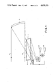
- FIG. 1 is a diagrammatic illustration of a telescope system embodying the present invention
- FIG. 2 is an illustration of the output of the spatial array of the invention.
- FIG. 3 is a diagram of the output of the spectral array of the invention, the spatial array being shown superimposed thereon.
- a Mersenne telescope arrangement positioned to receive the rays R from a field of view. It comprises a primary mirror 10 and secondary mirror 12, together with the usual field stop and Lyot stop (not shown).
- the radiation from the secondary mirror 12 is directed to a concave reflective optical grating 14.
- Two rectangular arrays of radiation detectors are positioned to receive the radiation reflected and diffracted from the grating 14. These may be, for example, arrays of charge-coupled devices (CCDs).
- a spatial array 16 is positioned to receive the zero order (undiffracted) radiation reflected from grating 14. This would nominally be broadband. This array might be, for example, 500 (M) pixels wide and 50 (N) pixels high. A strip field (i.e., M ⁇ N) is necessary to achieve the appropriate image quality.
- a spectral array 18 of similar detectors is positioned to receive radiation diffracted in first order at the central wavelength of interest from the grating 14.
- the exact position of a source in the field imaged by the grating 14 is wavelength dependent.
- the spectral array 18 may be 500 (M) pixels wide and 100 (N+W) pixels high.
- FIG. 1 illustrates the output from the spatial array 16 being supplied to a cathode ray tube (CRT) 20 and the output of the spectral array 18 being supplied to the input of a CRT 22.
- the spectral information from the spectral array 18 may be combined with the spatial information, for example, by means of a signal processor 24 which may be utilized to combine the outputs into a single display. In such a case, one cathode ray tube, such as CRT 22 may be eliminated.
- FIGS. 2 and 3 illustrate, in a simplified form, the manner in which the apparatus of the invention functions.
- FIG. 2 illustrates a 50 ⁇ 25 pixel portion of the spatial array 16.
- S 1 -S 5 five different simultaneous detections of focused radiation on objects in the field of view are shown, labeled S 1 -S 5 , respectively.
- unresolved focused irradiation it is meant that each source subtends only one pixel.
- the coordinates of S 1 for example, would be 3, 16 and those of S 3 would be 24, 12. These locations are independent of the wavelength of the irradiating sources.
- FIG. 3 illustrates a corresponding 50 ⁇ 50 pixel portion of the spectral array 18.
- the pixel numbers at which the focused radiation is detected are wavelength dependent, as the radiation is diffracted before reaching the array.
- the difference between the detected location of a source in the spectral array and the detected location in the spatial array provides the wavelength information. If each pixel corresponds to one (1%) percent of the wavelength ⁇ c , then the wavelength of the unknown sources can be readily obtained from the following calculations:
- an aperture diameter of the primary mirror 10 of 600 millimeters and a field of view of 2.0 ⁇ 0.2 degrees.
- the spectral resolution might be one (1%) percent ⁇ c and the spatial resolution could be 0.1 milliradian.
- the pixel size could be 0.25 ⁇ 0.25 millimeter and the grating could have a bandpass of one octave.
- the array sizes could be 500 by 50 pixels for the zero order array and 500 by 100 pixels for the first order array. Note that, while this instrument would contain 75000 pixels, the equivalent imaging spectrometer would require 1,250,000 pixels to obtain the same information.
Abstract
Description
______________________________________
                   Row  Column
______________________________________
S.sub.1 (λ.sub.1)
                     36      3
S.sub.1 (λ.sub.c)
                     28.5    3
λ.sub.1 = λ.sub.c + (36-28.5) × 1% λ.sub.c
S.sub.2 (λ.sub.2)
                     18     15
S.sub.2 (λ.sub.c)
                     22.5   15
λ.sub.2 = λ.sub.c + (18-22.5) × 1% λ.sub.c
S.sub.5 (λ.sub.5)
                     28     42
S.sub.5 (λ.sub.c)
                     30.5   42
λ.sub.5 = λ.sub.c + (28-30.5) × 1% λ.sub.c
______________________________________
Claims (8)
Priority Applications (1)
| Application Number | Priority Date | Filing Date | Title |
|---|---|---|---|
| US06/751,921 US4650321A (en) | 1985-07-05 | 1985-07-05 | Spatial/spectral real time imaging |
Applications Claiming Priority (1)
| Application Number | Priority Date | Filing Date | Title |
|---|---|---|---|
| US06/751,921 US4650321A (en) | 1985-07-05 | 1985-07-05 | Spatial/spectral real time imaging |
Publications (1)
| Publication Number | Publication Date |
|---|---|
| US4650321A true US4650321A (en) | 1987-03-17 |
Family
ID=25024090
Family Applications (1)
| Application Number | Title | Priority Date | Filing Date |
|---|---|---|---|
| US06/751,921 Expired - Lifetime US4650321A (en) | 1985-07-05 | 1985-07-05 | Spatial/spectral real time imaging |
Country Status (1)
| Country | Link |
|---|---|
| US (1) | US4650321A (en) |
Cited By (18)
| Publication number | Priority date | Publication date | Assignee | Title |
|---|---|---|---|---|
| US4729658A (en) * | 1986-06-05 | 1988-03-08 | The Perkin-Elmer Corporation | Very wide spectral coverage grating spectrometer |
| US4795253A (en) * | 1987-04-24 | 1989-01-03 | Mobay Corporation | Remote sensing gas analyzer |
| US4997281A (en) * | 1989-08-24 | 1991-03-05 | Stark Edward W | Grating spectrometer |
| US5112125A (en) * | 1988-12-24 | 1992-05-12 | Wild Leitz, Gmbh | Spectral microscope with a photometer |
| US5166755A (en) * | 1990-05-23 | 1992-11-24 | Nahum Gat | Spectrometer apparatus |
| US5305082A (en) * | 1992-01-08 | 1994-04-19 | Chromax, Inc. | High spatial resolution imaging spectrograph |
| US5369276A (en) * | 1992-07-01 | 1994-11-29 | The United States Of America As Represented By The Secretary Of The Army | Method and system for real-time wavelength identification for infrared detectors |
| US5926283A (en) * | 1997-07-12 | 1999-07-20 | Optical Insights, Llc | Multi-spectral two dimensional imaging spectrometer |
| US5982497A (en) * | 1998-07-09 | 1999-11-09 | Optical Insights, Llc | Multi-spectral two-dimensional imaging spectrometer |
| US6856466B2 (en) | 2001-07-05 | 2005-02-15 | Science & Engineering Associates, Inc. | Multiple imaging system |
| US7315371B2 (en) | 2004-01-23 | 2008-01-01 | P&P Optica Inc. | Multi-channel spectrum analyzer |
| US7907278B1 (en) | 2006-11-06 | 2011-03-15 | Lowell Williams | Staring imaging grating spectrometer for detection of projectiles |
| US20120008133A1 (en) * | 2010-07-09 | 2012-01-12 | Raytheon Company | System and method for hyperspectral and polarimetric imaging |
| US20130215404A1 (en) * | 2012-02-21 | 2013-08-22 | Asml Netherlands B.V. | Inspection Apparatus and Method |
| US20140339438A1 (en) * | 2013-05-16 | 2014-11-20 | Carl Zeiss Microscopy Gmbh | Devices and methods for spectroscopic analysis |
| CN104266755A (en) * | 2014-09-29 | 2015-01-07 | 上海交通大学 | Spectrum measurement method and system for improving luminous flux |
| US10830639B2 (en) | 2014-09-25 | 2020-11-10 | Northwestern University | Devices, methods, and systems relating to super resolution imaging |
| CN113960731A (en) * | 2021-11-11 | 2022-01-21 | 中国科学院长春光学精密机械与物理研究所 | Grating supporting device for space solar telescope |
Citations (6)
| Publication number | Priority date | Publication date | Assignee | Title |
|---|---|---|---|---|
| US3363525A (en) * | 1964-02-17 | 1968-01-16 | Beckman & Whitley Inc | Photography of spectral dispersion |
| US3992099A (en) * | 1973-12-12 | 1976-11-16 | Varo, Inc. | Source discriminator for measuring angle of arrival and wavelength of radiant energy |
| US4037959A (en) * | 1975-12-15 | 1977-07-26 | The United States Of America As Represented By The Secretary Of The Navy | Means for real-time laser source characterization |
| US4146332A (en) * | 1977-04-19 | 1979-03-27 | The United States Of America As Represented By The Secretary Of The Navy | Spectrometer with electronic readout |
| US4320462A (en) * | 1980-03-31 | 1982-03-16 | Hughes Aircraft Company | High speed laser pulse analyzer |
| US4346992A (en) * | 1969-02-07 | 1982-08-31 | Sanders Associates, Inc. | Laser detector and spectral analyzer |
-
1985
- 1985-07-05 US US06/751,921 patent/US4650321A/en not_active Expired - Lifetime
Patent Citations (6)
| Publication number | Priority date | Publication date | Assignee | Title |
|---|---|---|---|---|
| US3363525A (en) * | 1964-02-17 | 1968-01-16 | Beckman & Whitley Inc | Photography of spectral dispersion |
| US4346992A (en) * | 1969-02-07 | 1982-08-31 | Sanders Associates, Inc. | Laser detector and spectral analyzer |
| US3992099A (en) * | 1973-12-12 | 1976-11-16 | Varo, Inc. | Source discriminator for measuring angle of arrival and wavelength of radiant energy |
| US4037959A (en) * | 1975-12-15 | 1977-07-26 | The United States Of America As Represented By The Secretary Of The Navy | Means for real-time laser source characterization |
| US4146332A (en) * | 1977-04-19 | 1979-03-27 | The United States Of America As Represented By The Secretary Of The Navy | Spectrometer with electronic readout |
| US4320462A (en) * | 1980-03-31 | 1982-03-16 | Hughes Aircraft Company | High speed laser pulse analyzer |
Cited By (24)
| Publication number | Priority date | Publication date | Assignee | Title |
|---|---|---|---|---|
| US4729658A (en) * | 1986-06-05 | 1988-03-08 | The Perkin-Elmer Corporation | Very wide spectral coverage grating spectrometer |
| US4795253A (en) * | 1987-04-24 | 1989-01-03 | Mobay Corporation | Remote sensing gas analyzer |
| US5112125A (en) * | 1988-12-24 | 1992-05-12 | Wild Leitz, Gmbh | Spectral microscope with a photometer |
| US4997281A (en) * | 1989-08-24 | 1991-03-05 | Stark Edward W | Grating spectrometer |
| US5166755A (en) * | 1990-05-23 | 1992-11-24 | Nahum Gat | Spectrometer apparatus |
| US5305082A (en) * | 1992-01-08 | 1994-04-19 | Chromax, Inc. | High spatial resolution imaging spectrograph |
| US5369276A (en) * | 1992-07-01 | 1994-11-29 | The United States Of America As Represented By The Secretary Of The Army | Method and system for real-time wavelength identification for infrared detectors |
| US5926283A (en) * | 1997-07-12 | 1999-07-20 | Optical Insights, Llc | Multi-spectral two dimensional imaging spectrometer |
| US5982497A (en) * | 1998-07-09 | 1999-11-09 | Optical Insights, Llc | Multi-spectral two-dimensional imaging spectrometer |
| US6856466B2 (en) | 2001-07-05 | 2005-02-15 | Science & Engineering Associates, Inc. | Multiple imaging system |
| US7315371B2 (en) | 2004-01-23 | 2008-01-01 | P&P Optica Inc. | Multi-channel spectrum analyzer |
| US7907278B1 (en) | 2006-11-06 | 2011-03-15 | Lowell Williams | Staring imaging grating spectrometer for detection of projectiles |
| US20120008133A1 (en) * | 2010-07-09 | 2012-01-12 | Raytheon Company | System and method for hyperspectral and polarimetric imaging |
| US8189179B2 (en) * | 2010-07-09 | 2012-05-29 | Raytheon Company | System and method for hyperspectral and polarimetric imaging |
| EP2416136A3 (en) * | 2010-07-09 | 2013-03-27 | Raytheon Company | System and method for hyperspectral and polarimetric imaging |
| US20130215404A1 (en) * | 2012-02-21 | 2013-08-22 | Asml Netherlands B.V. | Inspection Apparatus and Method |
| US9222834B2 (en) * | 2012-02-21 | 2015-12-29 | Asml Netherlands B.V. | Inspection apparatus and method |
| US10274370B2 (en) | 2012-02-21 | 2019-04-30 | Asml Netherlands B.V. | Inspection apparatus and method |
| US20140339438A1 (en) * | 2013-05-16 | 2014-11-20 | Carl Zeiss Microscopy Gmbh | Devices and methods for spectroscopic analysis |
| US9927361B2 (en) * | 2013-05-16 | 2018-03-27 | Carl Zeiss Microscopy Gmbh | Devices and methods for spectroscopic analysis |
| US10436712B2 (en) | 2013-05-16 | 2019-10-08 | Carl Zeiss Microscopy Gmbh | Devices and methods for spectroscopic analysis |
| US10830639B2 (en) | 2014-09-25 | 2020-11-10 | Northwestern University | Devices, methods, and systems relating to super resolution imaging |
| CN104266755A (en) * | 2014-09-29 | 2015-01-07 | 上海交通大学 | Spectrum measurement method and system for improving luminous flux |
| CN113960731A (en) * | 2021-11-11 | 2022-01-21 | 中国科学院长春光学精密机械与物理研究所 | Grating supporting device for space solar telescope |
Similar Documents
| Publication | Publication Date | Title |
|---|---|---|
| US4650321A (en) | Spatial/spectral real time imaging | |
| AU731476B2 (en) | Multi-spectral two-dimensional imaging spectrometer | |
| US6313908B1 (en) | Apparatus and method using a holographic optical element for converting a spectral distribution to image points | |
| US4751571A (en) | Composite visible/thermal-infrared imaging apparatus | |
| CN101384945B (en) | Optically multiplexed imaging systems and methods of operation | |
| EP0829707A2 (en) | Compact fast imaging spectrometer | |
| EP0766112B1 (en) | Panoramic optics assembly having an initial flat reflective element | |
| GB2271845A (en) | Polarisation image detection systems | |
| US4585948A (en) | Non-scanning integrated optical system with wide field of view search capability | |
| US20040021766A1 (en) | Multispectral omnidirectional optical sensor and methods therefor | |
| US3508051A (en) | Employing a plurality of dichroic mirrors to produce a three-color image | |
| US3778166A (en) | Bipolar area correlator | |
| US11175181B2 (en) | Device for imaging and delivering spectroscopic information | |
| US5045695A (en) | Transition radiation interference spectrometer | |
| US3664741A (en) | Method and devices for the chromatic analysis of an object | |
| O'connor et al. | The Manchester occulting mask imager (MOMI): first results on the environment of P Cygni | |
| CN116183024B (en) | Spectrum imager based on fusion imaging is cut apart with spectral band to visual field | |
| Bagnuolo Jr et al. | High-resolution imaging of the M87 core | |
| RU2808963C1 (en) | Three-spectrum video surveillance system | |
| Senik | Color night-vision imaging rangefinder | |
| SU763700A1 (en) | Radiation videometer | |
| US3942008A (en) | Thermal imaging device | |
| RU2051398C1 (en) | Method and device for analyzing and synthesizing images | |
| GB2268022A (en) | Polarisation image detector | |
| RU2312372C2 (en) | Arrangement for detection and diagnostics of the sources of optical radiation |
Legal Events
| Date | Code | Title | Description |
|---|---|---|---|
| AS | Assignment |
Owner name: PERKIN-ELMER CORPORATION 761 MAIN AVE NORWALK CONN Free format text: ASSIGNMENT OF ASSIGNORS INTEREST.;ASSIGNOR:THOMPSON, KEVIN P.;REEL/FRAME:004426/0732 Effective date: 19850701 |
|
| STCF | Information on status: patent grant |
Free format text: PATENTED CASE |
|
| FEPP | Fee payment procedure |
Free format text: PAYOR NUMBER ASSIGNED (ORIGINAL EVENT CODE: ASPN); ENTITY STATUS OF PATENT OWNER: LARGE ENTITY |
|
| FPAY | Fee payment |
Year of fee payment: 4 |
|
| REMI | Maintenance fee reminder mailed | ||
| FEPP | Fee payment procedure |
Free format text: PAYER NUMBER DE-ASSIGNED (ORIGINAL EVENT CODE: RMPN); ENTITY STATUS OF PATENT OWNER: LARGE ENTITY Free format text: PAYOR NUMBER ASSIGNED (ORIGINAL EVENT CODE: ASPN); ENTITY STATUS OF PATENT OWNER: LARGE ENTITY |
|
| FPAY | Fee payment |
Year of fee payment: 8 |
|
| SULP | Surcharge for late payment | ||
| FP | Lapsed due to failure to pay maintenance fee |
Effective date: 19950322 |
|
| FPAY | Fee payment |
Year of fee payment: 12 |
|
| AS | Assignment |
Owner name: RAYTHEON OPTICAL SYSTEMS, INC., CONNECTICUT Free format text: ASSIGNMENT OF ASSIGNORS INTEREST;ASSIGNOR:HUGHES DANBURY OPTICAL SYSTEMS, INC.;REEL/FRAME:011190/0242 Effective date: 19971217 Owner name: RAYTHEON COMPANY, A CORPORATION OF DELAWARE, MASSA Free format text: MERGER;ASSIGNOR:RAYTHEON OPTICAL SYSTEMS, INC. A CORPORATION OF DELAWARE;REEL/FRAME:011190/0729 Effective date: 19981229 |
|
| AS | Assignment |
Owner name: HUGHES DANBURY OPTICAL SYSTEMS, INC., CONNECTICUT Free format text: ASSIGNMENT OF ASSIGNORS INTEREST;ASSIGNOR:PERKIN-ELMER CORPORATION, THE, A CORPORATION OF NEW YORK;REEL/FRAME:011219/0487 Effective date: 20010103 |
|
| AS | Assignment |
Owner name: B.F. GOODRICH COMPANY, THE, NORTH CAROLINA Free format text: ASSIGNMENT OF ASSIGNORS INTEREST;ASSIGNOR:RAYTHEON COMPANY;REEL/FRAME:011497/0102 Effective date: 20001227 |