US4655219A - Multicomponent flexible grasping device - Google Patents
Multicomponent flexible grasping device Download PDFInfo
- Publication number
- US4655219A US4655219A US06/880,333 US88033386A US4655219A US 4655219 A US4655219 A US 4655219A US 88033386 A US88033386 A US 88033386A US 4655219 A US4655219 A US 4655219A
- Authority
- US
- United States
- Prior art keywords
- accessory
- shaft
- forceps
- tubular
- sheath
- Prior art date
- Legal status (The legal status is an assumption and is not a legal conclusion. Google has not performed a legal analysis and makes no representation as to the accuracy of the status listed.)
- Expired - Lifetime
Links
Images


Classifications
-
- A—HUMAN NECESSITIES
- A61—MEDICAL OR VETERINARY SCIENCE; HYGIENE
- A61B—DIAGNOSIS; SURGERY; IDENTIFICATION
- A61B17/00—Surgical instruments, devices or methods, e.g. tourniquets
- A61B17/28—Surgical forceps
- A61B17/29—Forceps for use in minimally invasive surgery
- A61B17/2909—Handles
-
- A—HUMAN NECESSITIES
- A61—MEDICAL OR VETERINARY SCIENCE; HYGIENE
- A61B—DIAGNOSIS; SURGERY; IDENTIFICATION
- A61B1/00—Instruments for performing medical examinations of the interior of cavities or tubes of the body by visual or photographical inspection, e.g. endoscopes; Illuminating arrangements therefor
- A61B1/012—Instruments for performing medical examinations of the interior of cavities or tubes of the body by visual or photographical inspection, e.g. endoscopes; Illuminating arrangements therefor characterised by internal passages or accessories therefor
- A61B1/018—Instruments for performing medical examinations of the interior of cavities or tubes of the body by visual or photographical inspection, e.g. endoscopes; Illuminating arrangements therefor characterised by internal passages or accessories therefor for receiving instruments
-
- A—HUMAN NECESSITIES
- A61—MEDICAL OR VETERINARY SCIENCE; HYGIENE
- A61B—DIAGNOSIS; SURGERY; IDENTIFICATION
- A61B17/00—Surgical instruments, devices or methods, e.g. tourniquets
- A61B17/22—Implements for squeezing-off ulcers or the like on the inside of inner organs of the body; Implements for scraping-out cavities of body organs, e.g. bones; Calculus removers; Calculus smashing apparatus; Apparatus for removing obstructions in blood vessels, not otherwise provided for
- A61B17/221—Gripping devices in the form of loops or baskets for gripping calculi or similar types of obstructions
- A61B2017/2215—Gripping devices in the form of loops or baskets for gripping calculi or similar types of obstructions having an open distal end
-
- A—HUMAN NECESSITIES
- A61—MEDICAL OR VETERINARY SCIENCE; HYGIENE
- A61B—DIAGNOSIS; SURGERY; IDENTIFICATION
- A61B17/00—Surgical instruments, devices or methods, e.g. tourniquets
- A61B17/30—Surgical pincettes without pivotal connections
- A61B2017/303—Surgical pincettes without pivotal connections with four or more legs
Definitions
- This invention relates to an apparatus and to a method. More specifically, this invention concerns itself with a unique forceps-like assembly adapted for use in conjunction with endoscopic instruments; and a method for the grasping/manipulation of objects within a bodily cavity by such endoscopic instruments.
- this accessory can consist of an elongated shaft having a plurality of resilient fingers disposed on one end thereof. These fingers can be manipulated or alternatively are biased in a spaced apart relationship. The opposite end of the shaft is fitted with an actuator mechanism which enables both extention and operation of such fingers in the field of operative interest.
- This accessory generally consists of one other component, namely a tubular element or sheath, through which the elongated forceps shaft can be extended or withdrawn.
- This accessory is generally initially prepositioned within the channel provided therefor in an endoscopic instrument, the endoscopic instrument inserted by the physician into the patient and the distal end of the instrument manipulated so as to provide the physician with visual access to the field of operative interest.
- the physician may thereafter extend/advance the forceps from its channel within the endoscope so as to position the fingers thereof around an object to effect either its manipulation or eventual grasping and removal.
- the operation of the forceps of the type described hereinabove is traditionally dependent upon axial motion of the forceps relative to the endoscope to achieve opening and closing the grasp of these fingers.
- the physician is required to initially position the forceps in the manner described above and thereafter further advance the endoscopic instrument into the patient in the direction of the tissue/deposit so as to maintain the fingers of the forceps in a stationary position relative to the object which is to be grasped.
- the axial movement of the forceps assembly into the endoscope to effect closure thereof will cause the forceps to recede out of range of grasping distance of the object.
- U.S. Pat. Nos. 4,003,380; 4,174,715; 4,085,743 all disclose various accessory tools suitable for use in endoscopic instruments.
- Each of the devices disclosed by these patents reveals a forceps assembly comprising of an elongated shaft and two concentrically arranged tubular members.
- an elongated shaft (either disposed within a tubular member and the manipulative/operative components of the tool) is extended from the tube or withdrawn into it as a means of manipulating the functional implement of each such tool.
- compensatory axial motion of the endoscope is required to maintain the functional implement of the tool stationary relative to the site of operative interest.
- Yet another object of this invention is to provide an improved accessory forceps for use in endoscopic instruments in which the actuation and/or manipulation of the forceps is effected without any relative movement of the endoscope, vis-a-vis, the field of operative interest.
- Additional objects of this invention include a method for use of this improved forceps accessory in conjunction with an endoscopic instrument and the removal of tissue specimens with such improved accessory.
- This improved accessory can comprise a forceps-like element located on the distal end of an elongated shaft which is actuated by the releasing of confinement of the grasping fingers of such element through the withdrawal of a tubular sheath which envelops such fingers.
- the tool assembly is extended from its channel within the endoscope into the field of operative interest.
- Such extension of the distal end of the forceps from the channel results in release of constraint upon the fingers of the forceps which are biased in spaced-apart relationship to one another.
- the physician can thereafter position the forceps to engage the tissue specimen or obstructive deposit.
- the forceps can then grasp/manipulate such specimen or deposit by simply extending the tubular sheath along the shaft of the instrument in the direction of the tissue deposit.
- This extension of the tubular sheath is effected without any axial movement of the endoscope relative to the field of operative interest.
- the operation of this accessory in the above manner is critically dependent upon the ability to advance and retract the tubular sheath without relative axial movement of the endoscope.
- This type of forceps activation system greatly simplifies manipulation of the instrument by the physician and permits more precise control over the forceps itself.
- the forceps-like instrument is affixed to the distal end of an elongated shaft which in turn resides within the channel of a tubular sheath.
- This tubular sheath is further coaxially enveloped by a second tubular member or liner which is somewhat shorter in length than the tubular sheath.
- the overall dimensions of this three component accessory are precisely adapted for use in endoscopic instruments of the type commonly used by physicians in both examination and in non-evasive surgical procedures.
- the accessory assembly of the type described hereinabove is adapted for insertion within a forceps channel of existing endoscopic instrument. Upon location of the field of operative interest by the physician, the entire assembly is sufficiently extended from the distal end of the endoscopic shaft to position the distal end of the accessory in close proximity to the tissue speciment or obstructive deposit.
- the tubular sheath enveloping the shaft of the tool is then withdrawn through the control mechanism thereby expanding the fingers of forceps-like element on the distal end of the shaft in a space apart relation relative to the tissue or obstructive deposit.
- the endoscope then is advanced to position the fingers of forceps in range of grasping of the tissue sample or obstructive deposit. Subsequent to such positioning, the tubular member surrounding the shaft is advanced/extended so as to restrict the spread apart fingers at the end of the shaft to effect a grasping of the tissue/deposit. This grasping of the tissue/deposit is achieved without any relative movement of the endoscope.
- FIG. 1 is a perspective view of an endoscopic instrument equipped with the forceps-like assembly of this invention
- FIG. 2 is a side plan view of the forceps-like assembly of this invention wherein the grasping manipulative elements on the distal end are shown spread-apart;
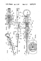
- FIG. 3 is a side plan view in partial section of the forceps-like assembly shown in FIG. 2;
- FIG. 4 is a top plan view of the forceps-like assembly shown in FIG. 2;
- FIG. 5 is an enlarged section view along the line 5--5 in FIG. 4;
- FIGS. 6, 7, 8 and 9 are side plan views in partial cross-section of the instrument shown in FIG. 1, FIGS. 6-9 depicted the forceps-like assembly in progressive stages of operation relative to a tissue specimen;
- FIG. 10 is a perspective view of another embodiment of the forceps-like assembly of the invention.
- FIG. 11 is a broken top plan view of the assembly of FIG. 10;
- FIG. 12 is a broken side view of the assembly of FIG. 10;
- FIG. 13 is an enlarged view in partial cross-section of the assembly of FIG. 10 taken along the line 13--13 in FIG. 12;
- FIG. 14 is an enlarged sectional view of the assembly of FIG. 10 taken along the line 14--14 in FIG. 13.
- an endoscope 20 is shown whose distal end 22 may be maneuvered and deflected in various positions under control by a deflection mechanism 24 located and mounted to the head 26 at the proximal end 28 of the endoscope 20.
- Endoscope 20 is provided with suitable channels to accommodate an image carrier fiber optic bundle and a light carrier fiber optic bundle so as to permit observation of tissues or other objects through an eye piece 30 and to enable coordination of manipulative procedures with instrument 32 involving certain accessories (i.e., forceps or electrodes) shown applied through a proximal port 34.
- the endoscope operator When in use, the endoscope operator observes an internal body cavity through an eye piece 30 while holding head 26 in his left hand (as illustrated in U.S. Pat. No. 4,207,873) with his fingers in contact with deflection control wheels 36 and 38 of deflection mechanism 24.
- the accessory 32 is of a type which incorporates at its distal end 40 a plurality of fingers 42 that are spring biased apart.
- the accessory 32 is a forceps with which an object may be grasped and/or manipulated.
- the accessory 32 incorporates a tool 44 having, at distal end 46 of accessory 32, flexible grasping arms 42 connected to an elongated shaft 48.
- the shaft 48 is connected to a holder 50 located at the proximal end 52 of accessory 32.
- Tool 48 is enclosed by a tubular sheath 54 which is connected at proximal end 52 to a slide 56 movably mounted to holder 50.
- slide 56 moves between the proximal and distal ends of holder 50, causes tubular sheath 54 to move relative to and over the flexible arms 42 as illustrated by FIGS. 2-4. With the slide 56 in the rear position shown in FIG.
- tubular sheath's distal end 58 is drawn away from the arms 42 which are unrestrained and thus flex to their maximum biased position.
- slide 56 is moved forwardly, the distal end 58 of tubular sheath 54 moves over the arms 42, thus forcing them to close.
- Accessory 32 overcomes the cumbersome nature of prior art forceps by the inclusion of an outer liner 60 in the form of an elongated tube.
- Liner 60 encloses most of tubular sheath 54 and is affixed to holder 50 at the latter's distal end 62.
- Liner 60 serves to maintain a working position of the accessory 32 in an endoscope channel while allowing tubular 54 to be easily moved back and forth under control by slide 56 to correspondingly control the opening and closure of arms 42.
- Liner 60 and tubular sheath 54 preferably interfit with each other in such manner that inner tube 54 may easily slide, with little backlash, within the liner 60 while the latter conveniently maintains a desired working position.
- One technique for maintaining the liner 60, and thus the accessory 32, at a desired working position relies upon the frictional force between the liner 60 and the wall of the endoscope channel through which the accessory 32 is passed.
- the length of the liner 60 may be so selected that accessory 32 develops a frictional force with the wall of the endoscope channel sufficient to maintain a working position in the channel under normal working conditions of the endoscope 20 and accessory 32.
- Another technique for generating such frictional endoscopic portion may utilize a restriction device (not shown) placed, for example, at port 34 (see FIG. 1) leading to the endoscope channel.
- Such restriction device would have a through bore sized, or formed with a frictional wall material, to develop sufficient frictional force with liner 60 without unduly affecting the movement of the tubular sheath 54.
- both the liner 60 and the tubular sheath 54 are each made of polytetrafluoroethylene material (i.e., Teflon, a product of E. I. du Pont de Nemours, Wilmington, Del., USA) and have cross-sectional dimensions so that, in case of tubular cylindrical construction, the inner diameter of liner 60 is greater than the outer diameter of tubular sheath 54 in the range from about 0.003 to about 0.007 inches, with a preferred difference of about 0.005 inches. With such clearance between the liner 60 and tubular sheath 54, and the use of low friction materials, the sheath 54 can be easily moved back and forth with little longitudinal backlash.
- polytetrafluoroethylene material i.e., Teflon, a product of E. I. du Pont de Nemours, Wilmington, Del., USA
- FIGS. 6-9 illustrate the distal end 46 of accessary 32 with greater detail inside a channel 64 of endoscope 20.
- Tubular sheath 54 is provided with a radially enlrged distal end 58 having a flared segment 66 and a straight cylindrical segment 68. This enables arms 42, when the slide 56 is at the distal end of its stroke, to recede inside tubular sheath 54 and also reduce stresses imposed on the distal end 58 when an object, such as 70, is grasped and removed as shown in FIG. 9.
- the tubular sheath 54 may have a length of the order of about 19 inches and the liner a length of about 17 inches and interfit in a manner as described.
- Tool 44 includes four forceps arms 42 that are spring biased in spread-apart relation to each other as shown in FIGS. 2 and 6 and extend from elongated shaft 48.
- the shaft is preferably made from a plurality of twisted steel strands with the tips of arms 42 bent inwardly to form claws for grasping an object such as 70 (see FIGS. 6-9).
- the holder 50 includes an anterior bushing 72 at its distal end 62 having a central axial bore 74.
- Liner 60 is secured to bushing 72.
- the tubular sheath 54 and shaft 48 extend rearwardly through bushing passage 74 with the proximal end of shaft 48 secured to the proximal ring shaped portion 76 of holder 50.
- the ring portion 76 is sized to laterally receive the thumb as shown in FIG. 1.
- the proximal end of tubular sheath 54 is secured to slide 56.
- Holder 50 further includes two elongated guide rails 78, 80 which connect the anterior bushing 62 with the ring portion 76 of holder 50.
- the guide rails 76, 80 extend through slightly larger bores 82 in slide 56.
- Slide 56 is mounted for reciprocal sliding movement in the space 84 between ring portion 76 and bushing 62.
- the manner of using the accessory 32 in accordance with the present invention commences by inserting the distal end 22 of the endoscope 20 into a body cavity to, for example, first locate and then remove a stone or apply a bipolar treatment of tissue in medical procedures involving, for example, urological, hepatoscopy, gastroenterology or bronchiogenic investigations.
- the accessory 32 is inserted through endoscope channel 64 until the distal end of the instrument protrudes from the distal end 22 of endoscope 20.
- the slide 56 Prior to and during inserting of the accessory 32 through the endoscope channel 64, the slide 56 is moved to its most distal position to thereby close the arms 42 and thus enable the instrument to pass through channel 64.
- the physician using the endoscope observes an object 70 through the eye piece 30, he or she manipulates the endoscope 20 and accessory 32 until the arms 42 are in a position to grasp object 70.
- the physician uses the left hand (not shown) to support the endoscope body 26 and operate the control wheels 36, 38 to move the distal end 22.
- the right hand is used to slide accessory 32 longitudinally along endoscope channel 64 to a working position as shown in FIG. 6.
- FIGS. 10-14 illustrate a preferred form for accessory 32 relating to the techniques for affixing the proximal ends of the tool 44, the tubular sheath 54 and liner 60 to holder 50 shown in detail.
- Holder 50 is formed with a ring shaped proximal end 76 affixed to a rectangular cross-sectional mid-segment 90 split into guide rods 78', 80' having flat facing slide surfaces.
- the distal end 62 of holder 50 is formed with an externally threaded segment 92 terminating in a conically tapered end 94 sized to snugly fit against a correspondingly shaped proximal flared end 96 of liner 60.
- a clamp 98 having a through bore 100 sized to snugly receive the outside diameter of the liner 60 has a conical clamping surface 102 that complements surface 94.
- Clamp 98 has a threaded bore 104 that meshes with the threaded segment 92 to firmly press and affix the liner end 96 to holder 50'.
- Segment 92 has a bore 106 sized to freely receive the tubular sheath 54 which is affixed to a slide connector 108 sized to fit, with slight clearance sufficient to slidingly move, between the flat facing surfaces 81, 83 of guide rods 78', 80'.
- Slide connector 108 has a through bore 110 which at its distal end is sized to snugly receive the tubular sheath 54.
- At the other proximal end bore 110 has a conical tapered surface 112 against which a correspondingly flared proximal end of the tubular sheath 54 is pressed by a clamp 114 having a mating end surface 115 and an externally threaded surface 116 to engage a correspondingly threaded bore 118. Clamp 114 thus affixes the tubular sheath 54 to slide 56' in a manner similar to clamp 92.
- Slide connector 108 is provided with a pair of laterally facing slots 120, 120' each of which may receive a set screw 121 enabling an outer slide block 122 to be affixed to connector 108 with set screws 121.
- Clamp 114 has a through bore 126 sized to freely receive the shaft 48 of tool 44.
- the shaft 48 extends through bore 126 to connect to ring end 76 by passing the tool shaft 48 thorugh a bore 130 and clamping the shaft 48 against a wall of bore 130 with a set screw 132.
- the slide block 122 is provided with a rectangular shaped through bore 134 sized to snugly enclose midsegment 90 of holder 50 while yet permitting sliding movement between ring shaped end 76 and clamp 98.
- accessory 32 as shown in FIGS. 10-14, a precise and delicate control over the opening and closure of tool arms 42 is obtained.
Abstract
Description
Claims (6)
Priority Applications (1)
| Application Number | Priority Date | Filing Date | Title |
|---|---|---|---|
| US06/880,333 US4655219A (en) | 1983-07-22 | 1986-06-24 | Multicomponent flexible grasping device |
Applications Claiming Priority (2)
| Application Number | Priority Date | Filing Date | Title |
|---|---|---|---|
| US51622583A | 1983-07-22 | 1983-07-22 | |
| US06/880,333 US4655219A (en) | 1983-07-22 | 1986-06-24 | Multicomponent flexible grasping device |
Related Parent Applications (1)
| Application Number | Title | Priority Date | Filing Date |
|---|---|---|---|
| US51622583A Continuation | 1983-07-22 | 1983-07-22 |
Publications (1)
| Publication Number | Publication Date |
|---|---|
| US4655219A true US4655219A (en) | 1987-04-07 |
Family
ID=27058765
Family Applications (1)
| Application Number | Title | Priority Date | Filing Date |
|---|---|---|---|
| US06/880,333 Expired - Lifetime US4655219A (en) | 1983-07-22 | 1986-06-24 | Multicomponent flexible grasping device |
Country Status (1)
| Country | Link |
|---|---|
| US (1) | US4655219A (en) |
Cited By (207)
| Publication number | Priority date | Publication date | Assignee | Title |
|---|---|---|---|---|
| US4750475A (en) * | 1985-08-14 | 1988-06-14 | Kabushiki Kaisha Machida Seisakusho | Operating instrument guide mechanism for endoscope apparatus |
| US4862885A (en) * | 1988-05-25 | 1989-09-05 | Cumming J Stuart | Instrument for inserting a deformable intraocular lens into the eye |
| US4887612A (en) * | 1988-04-27 | 1989-12-19 | Esco Precision, Inc. | Endoscopic biopsy forceps |
| US4909789A (en) * | 1986-03-28 | 1990-03-20 | Olympus Optical Co., Ltd. | Observation assisting forceps |
| US4945920A (en) * | 1988-03-28 | 1990-08-07 | Cordis Corporation | Torqueable and formable biopsy forceps |
| US4976723A (en) * | 1988-07-26 | 1990-12-11 | Karl Schad | Specimen excision forceps |
| EP0410561A1 (en) * | 1989-07-28 | 1991-01-30 | C.R. Bard, Inc. | Grasping forceps |
| WO1991002493A1 (en) * | 1989-08-16 | 1991-03-07 | Raychem Corporation | A device for grasping or cutting an object |
| US5052402A (en) * | 1989-01-31 | 1991-10-01 | C.R. Bard, Inc. | Disposable biopsy forceps |
| US5152779A (en) * | 1989-08-11 | 1992-10-06 | Olympus Optical Co., Ltd. | Forceps instrument |
| US5172700A (en) * | 1989-01-31 | 1992-12-22 | C. R. Bard, Inc. | Disposable biopsy forceps |
| US5199419A (en) * | 1991-08-05 | 1993-04-06 | United States Surgical Corporation | Surgical retractor |
| US5201739A (en) * | 1988-05-17 | 1993-04-13 | Wisap Gesellschaft Fur Wissenschaftlichen Apparatebau Mbh | Medical instrument |
| EP0543107A2 (en) * | 1991-10-18 | 1993-05-26 | United States Surgical Corporation | Handle for endoscopic surgical instruments and jaw structure |
| US5222973A (en) * | 1992-03-09 | 1993-06-29 | Sharpe Endosurgical Corporation | Endoscopic grasping tool surgical instrument |
| US5224954A (en) * | 1991-02-19 | 1993-07-06 | Dexide, Inc. | Combination surgical trocar cannula and rake assembly |
| US5271385A (en) * | 1990-03-29 | 1993-12-21 | United States Surgical Corporation | Abdominal cavity organ retractor |
| EP0575719A1 (en) * | 1992-06-20 | 1993-12-29 | Angiomed Ag | Apparatus for the correction of the position of a stent |
| EP0590136A1 (en) | 1992-04-15 | 1994-04-06 | Microsurge, Inc. | Surgical instrument for endoscopic surgery |
| US5312391A (en) * | 1992-07-29 | 1994-05-17 | Wilk Peter J | Laparoscopic instrument assembly |
| US5312432A (en) * | 1992-05-01 | 1994-05-17 | Vance Products Inc. | Percutaneously insertable, needle-sized tissue retractor and system |
| DE4243411A1 (en) * | 1992-12-17 | 1994-06-23 | Ethicon Gmbh | Surgical holder for counter-bearing circular suturing appts. |
| US5325866A (en) * | 1993-04-20 | 1994-07-05 | Jacek Krzyzanowski | Flexible biopsy forceps |
| US5325848A (en) * | 1992-09-10 | 1994-07-05 | Ethicon, Inc. | Endoscopic tissue manipulator with expandable frame |
| WO1994015533A2 (en) * | 1993-01-18 | 1994-07-21 | John Crowe | Endoscope forceps |
| US5339801A (en) * | 1992-03-12 | 1994-08-23 | Uresil Corporation | Surgical retractor and surgical method |
| US5351679A (en) * | 1992-08-17 | 1994-10-04 | Ilya Mayzels | Surgical endoscopic retractor instrument |
| US5358496A (en) * | 1991-10-18 | 1994-10-25 | Ethicon, Inc. | Endoscopic tissue manipulator |
| US5395367A (en) * | 1992-07-29 | 1995-03-07 | Wilk; Peter J. | Laparoscopic instrument with bendable shaft and removable actuator |
| US5395383A (en) * | 1991-10-18 | 1995-03-07 | Ethicon, Inc. | Adhesion barrier applicator |
| US5397332A (en) * | 1993-09-02 | 1995-03-14 | Ethicon, Inc. | Surgical mesh applicator |
| US5403326A (en) * | 1993-02-01 | 1995-04-04 | The Regents Of The University Of California | Method for performing a gastric wrap of the esophagus for use in the treatment of esophageal reflux |
| US5405360A (en) * | 1992-02-24 | 1995-04-11 | United States Surgical Corporation | Resilient arm mesh deployer |
| WO1995033407A1 (en) * | 1994-06-06 | 1995-12-14 | Valleylab Inc. | Surgical spreader assembly and associated method |
| US5476479A (en) * | 1991-09-26 | 1995-12-19 | United States Surgical Corporation | Handle for endoscopic surgical instruments and jaw structure |
| FR2725611A1 (en) * | 1994-10-18 | 1996-04-19 | Gestra Groupe D Etudes Specifi | Extraction and protection sleeve for catheter needle |
| US5509923A (en) * | 1989-08-16 | 1996-04-23 | Raychem Corporation | Device for dissecting, grasping, or cutting an object |
| US5512037A (en) * | 1994-05-12 | 1996-04-30 | United States Surgical Corporation | Percutaneous surgical retractor |
| US5511564A (en) * | 1992-07-29 | 1996-04-30 | Valleylab Inc. | Laparoscopic stretching instrument and associated method |
| US5549595A (en) * | 1991-05-24 | 1996-08-27 | Dexide, Inc. | Gear activated trocar assembly |
| US5556371A (en) * | 1992-02-22 | 1996-09-17 | Kernforschungszentrum Karlsruhe Gmbh | Device for transanal resectate extraction |
| US5571116A (en) * | 1994-10-02 | 1996-11-05 | United States Surgical Corporation | Non-invasive treatment of gastroesophageal reflux disease |
| US5599279A (en) * | 1994-03-16 | 1997-02-04 | Gus J. Slotman | Surgical instruments and method useful for endoscopic spinal procedures |
| US5620458A (en) * | 1994-03-16 | 1997-04-15 | United States Surgical Corporation | Surgical instruments useful for endoscopic spinal procedures |
| WO1997017021A1 (en) * | 1995-11-07 | 1997-05-15 | Dereume Jean Pierre Georges Em | Retrieval device for insertion into a body lumen |
| US5634918A (en) * | 1994-10-26 | 1997-06-03 | Grieshaber & Co. Ag Schaffhausen | Ophthalmic surgical instrument |
| EP0793450A1 (en) | 1994-11-21 | 1997-09-10 | Boston Scientific Corporation | Surgical retrieval baskets and method for making the same |
| US5667525A (en) * | 1994-08-25 | 1997-09-16 | Olympus Optical Co. | Grasping forceps for endoscope |
| US5676678A (en) * | 1993-07-17 | 1997-10-14 | Schad; Gerhard | Surgical instrument with releasable jaw holder |
| EP0812155A1 (en) | 1995-02-02 | 1997-12-17 | Boston Scientific Corporation | Surgical wire basket extractor |
| EP0813842A2 (en) * | 1996-06-11 | 1997-12-29 | Asahi Kogaku Kogyo Kabushiki Kaisha | Treatment accessory for endoscope |
| DE19630324A1 (en) * | 1996-07-26 | 1998-01-29 | Herbert Maslanka | Surgical endoscope flexible operating cable |
| US5713870A (en) * | 1991-11-27 | 1998-02-03 | Yoon; Inbae | Retractable safety penetrating instrument with laterally extendable spring strip |
| US5718703A (en) * | 1993-09-17 | 1998-02-17 | Origin Medsystems, Inc. | Method and apparatus for small needle electrocautery |
| US5782747A (en) * | 1996-04-22 | 1998-07-21 | Zimmon Science Corporation | Spring based multi-purpose medical instrument |
| US5868754A (en) * | 1996-06-12 | 1999-02-09 | Target Therapeutics, Inc. | Medical retrieval device |
| US5891017A (en) * | 1997-01-31 | 1999-04-06 | Baxter Research Medical, Inc. | Surgical stabilizer and method for isolating and immobilizing cardiac tissue |
| EP0818180A3 (en) * | 1996-07-10 | 1999-05-06 | Asahi Kogaku Kogyo Kabushiki Kaisha | Treatment accessory for endoscope |
| US5944728A (en) * | 1998-04-23 | 1999-08-31 | Boston Scientific Corporation | Surgical retrieval basket with the ability to capture and release material |
| US5957932A (en) * | 1996-04-30 | 1999-09-28 | Boston Scientific Corporation | Calculus removal |
| US6090129A (en) * | 1996-06-11 | 2000-07-18 | Asahi Kogaku Kogyo Kabushiki Kaisha | Treatment accessory for endoscope |
| US6099534A (en) * | 1997-10-01 | 2000-08-08 | Scimed Life Systems, Inc. | Releasable basket |
| FR2794653A1 (en) * | 1999-06-14 | 2000-12-15 | Sarl Aln | KIT FOR THE REMOVAL OF A BLADDER VESSEL FILTER OF THE UMBRELLA TYPE |
| US6217587B1 (en) | 1997-10-09 | 2001-04-17 | Olympus Optical Co., Ltd. | Treatment tool for an endoscope |
| US6224612B1 (en) | 1998-04-23 | 2001-05-01 | Scimed Life Systems, Inc. | Atraumatic medical retrieval device |
| EP1123126A1 (en) * | 1998-09-24 | 2001-08-16 | Scimed Life Systems, Inc. | Retrieval devices for vena cava filter |
| US6280464B1 (en) * | 1998-01-09 | 2001-08-28 | Endovascular Technologies, Inc. | Prosthesis gripping system and method |
| US6338738B1 (en) | 1999-08-31 | 2002-01-15 | Edwards Lifesciences Corp. | Device and method for stabilizing cardiac tissue |
| US6348056B1 (en) | 1999-08-06 | 2002-02-19 | Scimed Life Systems, Inc. | Medical retrieval device with releasable retrieval basket |
| US6350266B1 (en) | 1995-02-02 | 2002-02-26 | Scimed Life Systems, Inc. | Hybrid stone retrieval device |
| US20020151909A1 (en) * | 2001-03-09 | 2002-10-17 | Gellman Barry N. | System for implanting an implant and method thereof |
| US20020198551A1 (en) * | 1999-11-16 | 2002-12-26 | Grant Kevin Lee | Endoscopic tissue separator surgical device |
| US6506209B2 (en) * | 2000-03-10 | 2003-01-14 | Pentax Corporation | Endoscopic foreign body retrieving tool |
| US20030023247A1 (en) * | 2001-07-03 | 2003-01-30 | Lind Stuart J. | Medical retrieval device with cable protection means |
| US6605104B2 (en) | 1994-08-02 | 2003-08-12 | Olympus Optical Co., Ltd. | Grasping forceps for endoscope |
| US20030163128A1 (en) * | 2000-12-29 | 2003-08-28 | Afx, Inc. | Tissue ablation system with a sliding ablating device and method |
| US6673100B2 (en) | 2001-05-25 | 2004-01-06 | Cordis Neurovascular, Inc. | Method and device for retrieving embolic coils |
| US20040078044A1 (en) * | 2002-10-18 | 2004-04-22 | Scimed Life Systems, Inc. | Medical retrieval device |
| US20040106937A1 (en) * | 2002-06-21 | 2004-06-03 | Afx, Inc. | Clamp accessory and method for an ablation instrument |
| US20040260339A1 (en) * | 1999-02-22 | 2004-12-23 | Roberto Pedros | Arterial hole closure apparatus |
| US20050070764A1 (en) * | 2003-09-29 | 2005-03-31 | Rudolph Nobis | Handle for endoscopic device |
| US6945984B2 (en) * | 2001-08-23 | 2005-09-20 | Alcon Grieshaber Ag | Micro surgical instrument |
| US20050234503A1 (en) * | 1998-09-25 | 2005-10-20 | Ravenscroft Adrian C | Removeable embolus blood clot filter and filter delivery unit |
| US6976986B2 (en) | 2000-04-12 | 2005-12-20 | Afx, Inc. | Electrode arrangement for use in a medical instrument |
| US20060052799A1 (en) * | 1989-08-16 | 2006-03-09 | Medtronic Vascular, Inc. | Method of manipulating matter in a mammalian body |
| US20060058832A1 (en) * | 2002-12-12 | 2006-03-16 | Andreas Melzer | Vessel filter |
| US7025772B2 (en) | 2001-03-09 | 2006-04-11 | Scimed Life Systems, Inc. | System for implanting an implant and method thereof |
| US7033352B1 (en) | 2000-01-18 | 2006-04-25 | Afx, Inc. | Flexible ablation instrument |
| US7037276B2 (en) | 2002-07-02 | 2006-05-02 | Precision Medical Devices, Inc. | Biopsy device |
| US7052491B2 (en) | 1998-10-23 | 2006-05-30 | Afx, Inc. | Vacuum-assisted securing apparatus for a microwave ablation instrument |
| US7099717B2 (en) | 2002-01-03 | 2006-08-29 | Afx Inc. | Catheter having improved steering |
| US20060247572A1 (en) * | 2005-04-28 | 2006-11-02 | C. R. Bard, Inc. | Medical device removal system |
| US7169154B1 (en) | 1999-05-25 | 2007-01-30 | Scimedlife Systems, Inc. | Releasable basket and method of making thereof |
| US7192427B2 (en) | 2002-02-19 | 2007-03-20 | Afx, Inc. | Apparatus and method for assessing transmurality of a tissue ablation |
| US7226446B1 (en) | 1999-05-04 | 2007-06-05 | Dinesh Mody | Surgical microwave ablation assembly |
| US20070179520A1 (en) * | 2006-01-31 | 2007-08-02 | Stephen West | Embolic device delivery system |
| US20070202151A1 (en) * | 2005-08-11 | 2007-08-30 | Massachusetts Institute Of Technology | Intravesical drug delivery device and method |
| US7303560B2 (en) | 2000-12-29 | 2007-12-04 | Afx, Inc. | Method of positioning a medical instrument |
| WO2008008384A2 (en) | 2006-07-14 | 2008-01-17 | Wilson-Cook Medical Inc. | Papilla spreader |
| US7346399B2 (en) | 1999-05-28 | 2008-03-18 | Afx, Inc. | Monopole tip for ablation catheter |
| US7361138B2 (en) | 2003-07-31 | 2008-04-22 | Scimed Life Systems, Inc. | Bioabsorbable casing for surgical sling assembly |
| US7402133B2 (en) | 2002-12-17 | 2008-07-22 | Boston Scientific Scimed, Inc. | Spacer for sling delivery system |
| US20090112062A1 (en) * | 2007-10-31 | 2009-04-30 | Bakos Gregory J | Detachable distal overtube section and methods for forming a sealable opening in the wall of an organ |
| US20090131970A1 (en) * | 2005-08-09 | 2009-05-21 | C.R. Bard Inc. | Embolus blood clot filter and delivery system |
| US20090149833A1 (en) * | 2007-12-11 | 2009-06-11 | Massachusetts Institute Of Technology | Implantable Drug Delivery Device and Methods for Treatment of the Bladder and Other Body Vesicles or Lumens |
| US20090192485A1 (en) * | 2008-01-28 | 2009-07-30 | Heuser Richard R | Snare device |
| US20090227828A1 (en) * | 2008-03-10 | 2009-09-10 | Ethicon Endo-Surgery, Inc. | Anastomotic device |
| US20090264919A1 (en) * | 2008-04-18 | 2009-10-22 | Medtronic Vascular, Inc. | Vascular Puncture Closure |
| US20090299404A1 (en) * | 2006-05-02 | 2009-12-03 | C.R. Bard, Inc. | Vena cava filter formed from a sheet |
| US20100003297A1 (en) * | 2005-08-11 | 2010-01-07 | Massachusetts Institute Of Technology | Implantable Drug Delivery Device and Methods of Treating Male Genitourinary and Surrounding Tissues |
| US20100030253A1 (en) * | 2005-11-18 | 2010-02-04 | C.R. Brard, Inc. | Vena cava filter with filament |
| US20100030254A1 (en) * | 2006-06-05 | 2010-02-04 | C. R. Bard, Inc. | Embolus Blood Clot Filter Utilizable With A Single Delivery System Or A Single Retrieval System In One of A Femoral or Jugular Access |
| US20100042045A1 (en) * | 2008-08-15 | 2010-02-18 | Ethicon Endo-Surgery, Inc. | Sterile appliance delivery device for endoscopic procedures |
| US20100049190A1 (en) * | 2008-08-25 | 2010-02-25 | Ethicon Endo-Surgery, Inc. | Electrical ablation devices |
| US20100057108A1 (en) * | 2008-09-02 | 2010-03-04 | Ethicon Endo-Surgery, Inc. | Suturing device |
| US20100174310A1 (en) * | 2004-08-04 | 2010-07-08 | C. R. Bard, Inc. | Non-entangling vena cava filter |
| US20100174306A1 (en) * | 2007-07-11 | 2010-07-08 | Vladimir Mitelberg | Methods and Systems for Performing Submucosal Medical Procedures |
| US20100217151A1 (en) * | 2007-07-11 | 2010-08-26 | Zach Gostout | Methods and Systems for Performing Submucosal Medical Procedures |
| US20100256669A1 (en) * | 2005-12-02 | 2010-10-07 | C.R. Bard, Inc. | Helical Vena Cava Filter |
| US20110060309A1 (en) * | 2009-09-10 | 2011-03-10 | Taris Biomedical, Inc. | Implantable Device for Controlled Drug Delivery |
| US20110152923A1 (en) * | 2009-12-18 | 2011-06-23 | Ethicon Endo-Surgery, Inc. | Incision closure device |
| US20110152609A1 (en) * | 2009-12-17 | 2011-06-23 | Ethicon Endo-Surgery, Inc. | User interface support devices for endoscopic surgical instruments |
| US20110238078A1 (en) * | 2010-03-29 | 2011-09-29 | Cook Medical Technologies Llc | Device and method for positioning an implanted structure to facilitate removal |
| US8033983B2 (en) | 2001-03-09 | 2011-10-11 | Boston Scientific Scimed, Inc. | Medical implant |
| US8062325B2 (en) | 2006-07-31 | 2011-11-22 | Codman & Shurtleff, Inc. | Implantable medical device detachment system and methods of using the same |
| US8066689B2 (en) | 2007-07-11 | 2011-11-29 | Apollo Endosurgery, Inc. | Methods and systems for submucosal implantation of a device for diagnosis and treatment with a therapeutic agent |
| US20120041473A1 (en) * | 2009-05-06 | 2012-02-16 | A.L.N. | Extraction kit for a filter for the vena cava |
| US8128592B2 (en) | 2007-07-11 | 2012-03-06 | Apollo Endosurgery, Inc. | Methods and systems for performing submucosal medical procedures |
| DE102011009161A1 (en) | 2011-01-22 | 2012-07-26 | Katrin Lindenmayr | Device for removing tonsil stones in self-treatment, comprises cutting spoon, which is attached on shaft for actuation, where offset angle is made flexible between sixty degree and ninety degree |
| US8241204B2 (en) | 2008-08-29 | 2012-08-14 | Ethicon Endo-Surgery, Inc. | Articulating end cap |
| US8252057B2 (en) | 2009-01-30 | 2012-08-28 | Ethicon Endo-Surgery, Inc. | Surgical access device |
| US8262655B2 (en) | 2007-11-21 | 2012-09-11 | Ethicon Endo-Surgery, Inc. | Bipolar forceps |
| US8262563B2 (en) | 2008-07-14 | 2012-09-11 | Ethicon Endo-Surgery, Inc. | Endoscopic translumenal articulatable steerable overtube |
| US8337394B2 (en) | 2008-10-01 | 2012-12-25 | Ethicon Endo-Surgery, Inc. | Overtube with expandable tip |
| US8361066B2 (en) | 2009-01-12 | 2013-01-29 | Ethicon Endo-Surgery, Inc. | Electrical ablation devices |
| US8361112B2 (en) | 2008-06-27 | 2013-01-29 | Ethicon Endo-Surgery, Inc. | Surgical suture arrangement |
| US8366720B2 (en) | 2006-07-31 | 2013-02-05 | Codman & Shurtleff, Inc. | Interventional medical device system having an elongation retarding portion and method of using the same |
| US8403926B2 (en) | 2008-06-05 | 2013-03-26 | Ethicon Endo-Surgery, Inc. | Manually articulating devices |
| US8409200B2 (en) | 2008-09-03 | 2013-04-02 | Ethicon Endo-Surgery, Inc. | Surgical grasping device |
| US8425505B2 (en) | 2007-02-15 | 2013-04-23 | Ethicon Endo-Surgery, Inc. | Electroporation ablation apparatus, system, and method |
| US8496574B2 (en) | 2009-12-17 | 2013-07-30 | Ethicon Endo-Surgery, Inc. | Selectively positionable camera for surgical guide tube assembly |
| US8506564B2 (en) | 2009-12-18 | 2013-08-13 | Ethicon Endo-Surgery, Inc. | Surgical instrument comprising an electrode |
| US8523879B1 (en) | 2005-03-31 | 2013-09-03 | Stuart J. Lind | Stone retriever for flexible endoscopes having small diameter working channels |
| US8568410B2 (en) | 2007-08-31 | 2013-10-29 | Ethicon Endo-Surgery, Inc. | Electrical ablation surgical instruments |
| US8574261B2 (en) | 2005-05-12 | 2013-11-05 | C. R. Bard, Inc. | Removable embolus blood clot filter |
| US8579897B2 (en) | 2007-11-21 | 2013-11-12 | Ethicon Endo-Surgery, Inc. | Bipolar forceps |
| WO2012109598A3 (en) * | 2011-02-10 | 2013-11-14 | Sherwinter Danny A | Laparoscopic retractor |
| US8608652B2 (en) | 2009-11-05 | 2013-12-17 | Ethicon Endo-Surgery, Inc. | Vaginal entry surgical devices, kit, system, and method |
| US8613754B2 (en) | 2005-05-12 | 2013-12-24 | C. R. Bard, Inc. | Tubular filter |
| US8679003B2 (en) | 2008-05-30 | 2014-03-25 | Ethicon Endo-Surgery, Inc. | Surgical device and endoscope including same |
| US8771260B2 (en) | 2008-05-30 | 2014-07-08 | Ethicon Endo-Surgery, Inc. | Actuating and articulating surgical device |
| US8870895B2 (en) | 2001-07-05 | 2014-10-28 | Annex Medical, Inc. | Medical retrieval device with independent rotational means |
| US8888792B2 (en) | 2008-07-14 | 2014-11-18 | Ethicon Endo-Surgery, Inc. | Tissue apposition clip application devices and methods |
| US8929988B2 (en) | 2007-07-11 | 2015-01-06 | Apollo Endosurgery, Inc. | Methods and systems for submucosal implantation of a device for diagnosis and treatment of a body |
| US8939897B2 (en) | 2007-10-31 | 2015-01-27 | Ethicon Endo-Surgery, Inc. | Methods for closing a gastrotomy |
| US8942530B2 (en) | 2011-09-20 | 2015-01-27 | San Marino Capital, Inc. | Endoscope connector method and apparatus |
| US20150038994A1 (en) * | 2013-08-02 | 2015-02-05 | Covidien Lp | Devices, systems, and methods for providing surgical access and facilitating closure of surgical access openings |
| JP2015051259A (en) * | 2013-08-05 | 2015-03-19 | 三菱鉛筆株式会社 | Puncture tool |
| US8986199B2 (en) | 2012-02-17 | 2015-03-24 | Ethicon Endo-Surgery, Inc. | Apparatus and methods for cleaning the lens of an endoscope |
| US9005198B2 (en) | 2010-01-29 | 2015-04-14 | Ethicon Endo-Surgery, Inc. | Surgical instrument comprising an electrode |
| US9028483B2 (en) | 2009-12-18 | 2015-05-12 | Ethicon Endo-Surgery, Inc. | Surgical instrument comprising an electrode |
| US9049987B2 (en) | 2011-03-17 | 2015-06-09 | Ethicon Endo-Surgery, Inc. | Hand held surgical device for manipulating an internal magnet assembly within a patient |
| US9078662B2 (en) | 2012-07-03 | 2015-07-14 | Ethicon Endo-Surgery, Inc. | Endoscopic cap electrode and method for using the same |
| US9101383B1 (en) | 2003-04-25 | 2015-08-11 | Annex Medical, Inc. | Medical retrieval device |
| US9107816B2 (en) | 2011-02-04 | 2015-08-18 | Taris Biomedical Llc | Implantable device for controlled dissolution and diffusion of low solubility drug |
| US9114111B2 (en) | 2011-01-10 | 2015-08-25 | Allergan, Inc. | Methods for sustained treatment of bladder pain and irritative voiding |
| US9204956B2 (en) | 2002-02-20 | 2015-12-08 | C. R. Bard, Inc. | IVC filter with translating hooks |
| US9220526B2 (en) | 2008-11-25 | 2015-12-29 | Ethicon Endo-Surgery, Inc. | Rotational coupling device for surgical instrument with flexible actuators |
| US9226772B2 (en) | 2009-01-30 | 2016-01-05 | Ethicon Endo-Surgery, Inc. | Surgical device |
| US9233241B2 (en) | 2011-02-28 | 2016-01-12 | Ethicon Endo-Surgery, Inc. | Electrical ablation devices and methods |
| US20160008003A1 (en) * | 2013-03-15 | 2016-01-14 | Covidien Lp | Delivery and detachment mechanisms for vascular |
| US9254169B2 (en) | 2011-02-28 | 2016-02-09 | Ethicon Endo-Surgery, Inc. | Electrical ablation devices and methods |
| US9265514B2 (en) | 2012-04-17 | 2016-02-23 | Miteas Ltd. | Manipulator for grasping tissue |
| US9277957B2 (en) | 2012-08-15 | 2016-03-08 | Ethicon Endo-Surgery, Inc. | Electrosurgical devices and methods |
| US9307996B2 (en) | 2005-12-13 | 2016-04-12 | DePuy Synthes Products, Inc. | Detachment actuator for use with medical device deployment systems |
| US9314620B2 (en) | 2011-02-28 | 2016-04-19 | Ethicon Endo-Surgery, Inc. | Electrical ablation devices and methods |
| US9427255B2 (en) | 2012-05-14 | 2016-08-30 | Ethicon Endo-Surgery, Inc. | Apparatus for introducing a steerable camera assembly into a patient |
| US20160331369A9 (en) * | 2013-03-15 | 2016-11-17 | Novasurg Innovations, Llc | Needle driver |
| US9511238B2 (en) | 2012-07-26 | 2016-12-06 | Nyxoah SA | Implant holder and suture guide |
| US9545290B2 (en) | 2012-07-30 | 2017-01-17 | Ethicon Endo-Surgery, Inc. | Needle probe guide |
| US9572623B2 (en) | 2012-08-02 | 2017-02-21 | Ethicon Endo-Surgery, Inc. | Reusable electrode and disposable sheath |
| US9844664B2 (en) | 2015-10-12 | 2017-12-19 | Medtronic, Inc. | Interventional medical systems, catheters, and subassemblies |
| US9848763B2 (en) | 2008-05-15 | 2017-12-26 | Apollo Endosurgery Us, Inc. | Access systems and methods of intra-abdominal surgery |
| US9949816B2 (en) | 2013-06-14 | 2018-04-24 | Avantec Vascular Corporation | IVC filter retrieval systems with multiple capture modes |
| US10080888B2 (en) | 2015-11-16 | 2018-09-25 | Medtronic, Inc. | Interventional medical systems and associated methods |
| US20180271636A1 (en) * | 2015-12-10 | 2018-09-27 | Avantec Vascular Corporation | Ivc filter retrieval system sheath improvements |
| US10092291B2 (en) | 2011-01-25 | 2018-10-09 | Ethicon Endo-Surgery, Inc. | Surgical instrument with selectively rigidizable features |
| US10098527B2 (en) | 2013-02-27 | 2018-10-16 | Ethidcon Endo-Surgery, Inc. | System for performing a minimally invasive surgical procedure |
| US10117661B2 (en) | 2014-05-30 | 2018-11-06 | Cook Medical Technologies Llc | Stone extracting medical device with better stone retention |
| US20180333299A1 (en) * | 2015-11-12 | 2018-11-22 | Mor Research Applications Ltd. | Instrument for extracting nucleus of eye lens during cataract surgery |
| US10137078B2 (en) | 2009-06-26 | 2018-11-27 | Taris Biomedical Llc | Methods for intravesical drug delivery and methods and systems for loading devices with drug tablets |
| AU2014228128B2 (en) * | 2013-03-15 | 2019-02-28 | Syed M. Hussain | Needle driver |
| US10278804B2 (en) | 2014-12-12 | 2019-05-07 | Avantec Vascular Corporation | IVC filter retrieval systems with releasable capture feature |
| US10286199B2 (en) | 2013-03-15 | 2019-05-14 | Taris Biomedical Llc | Drug delivery devices with drug-permeable component and methods |
| US10314634B2 (en) | 2014-11-04 | 2019-06-11 | Avantec Vascular Corporation | Catheter device with longitudinally expanding interior components for compressing cancellous bone |
| US10314649B2 (en) | 2012-08-02 | 2019-06-11 | Ethicon Endo-Surgery, Inc. | Flexible expandable electrode and method of intraluminal delivery of pulsed power |
| US10631836B2 (en) | 2016-04-07 | 2020-04-28 | Gyrus Acmi, Inc. | Laparoscopic surgical device with flared tube |
| US10729823B2 (en) | 2013-08-19 | 2020-08-04 | Taris Biomedical Llc | Multi-unit drug delivery devices and methods |
| US10758729B2 (en) | 2015-10-01 | 2020-09-01 | Medtronic, Inc. | Interventional medical systems, catheters, and methods |
| US10779882B2 (en) | 2009-10-28 | 2020-09-22 | Ethicon Endo-Surgery, Inc. | Electrical ablation devices |
| US10856962B2 (en) | 2014-12-12 | 2020-12-08 | Avantec Vascular Corporation | IVC filter retrieval systems with interposed support members |
| US10874499B2 (en) | 2016-12-22 | 2020-12-29 | Avantec Vascular Corporation | Systems, devices, and methods for retrieval systems having a tether |
| US10894150B2 (en) | 2015-04-23 | 2021-01-19 | Taris Biomedical Llc | Drug delivery devices with drug-permeable component and methods |
| US11090081B2 (en) | 2015-07-10 | 2021-08-17 | Medtronic, Inc. | Extravascular medical access tools having boring tip and methods of using such tools |
| US11129609B2 (en) | 2018-04-24 | 2021-09-28 | Covidien Lp | Devices, systems, and methods for providing surgical access and facilitating closure of surgical access openings |
| US11490914B2 (en) | 2020-10-07 | 2022-11-08 | Christopher Murphy | Dual operation grasping forceps for endoscope |
| US11833025B2 (en) | 2018-06-29 | 2023-12-05 | Avantec Vascular Corporation | Systems and methods for implants and deployment devices |
Citations (6)
| Publication number | Priority date | Publication date | Assignee | Title |
|---|---|---|---|---|
| US3529633A (en) * | 1967-10-23 | 1970-09-22 | Bard Inc C R | X-ray opaque tubing having a transparent stripe |
| US3934589A (en) * | 1973-05-26 | 1976-01-27 | Dragerwerk Aktiengesellschaft | Surgical instrument for sterilizing women by ligature of tubes |
| US4003380A (en) * | 1974-09-05 | 1977-01-18 | F.L. Fisher | Bipolar coagulation instrument |
| US4085743A (en) * | 1976-03-02 | 1978-04-25 | In Bae Yoon | Multiple occlusion ring applicator and method |
| US4174715A (en) * | 1977-03-28 | 1979-11-20 | Hasson Harrith M | Multi-pronged laparoscopy forceps |
| US4467802A (en) * | 1980-03-31 | 1984-08-28 | Harald Maslanka | Surgical gripping instrument |
-
1986
- 1986-06-24 US US06/880,333 patent/US4655219A/en not_active Expired - Lifetime
Patent Citations (6)
| Publication number | Priority date | Publication date | Assignee | Title |
|---|---|---|---|---|
| US3529633A (en) * | 1967-10-23 | 1970-09-22 | Bard Inc C R | X-ray opaque tubing having a transparent stripe |
| US3934589A (en) * | 1973-05-26 | 1976-01-27 | Dragerwerk Aktiengesellschaft | Surgical instrument for sterilizing women by ligature of tubes |
| US4003380A (en) * | 1974-09-05 | 1977-01-18 | F.L. Fisher | Bipolar coagulation instrument |
| US4085743A (en) * | 1976-03-02 | 1978-04-25 | In Bae Yoon | Multiple occlusion ring applicator and method |
| US4174715A (en) * | 1977-03-28 | 1979-11-20 | Hasson Harrith M | Multi-pronged laparoscopy forceps |
| US4467802A (en) * | 1980-03-31 | 1984-08-28 | Harald Maslanka | Surgical gripping instrument |
Cited By (392)
| Publication number | Priority date | Publication date | Assignee | Title |
|---|---|---|---|---|
| US4750475A (en) * | 1985-08-14 | 1988-06-14 | Kabushiki Kaisha Machida Seisakusho | Operating instrument guide mechanism for endoscope apparatus |
| US4909789A (en) * | 1986-03-28 | 1990-03-20 | Olympus Optical Co., Ltd. | Observation assisting forceps |
| US4945920A (en) * | 1988-03-28 | 1990-08-07 | Cordis Corporation | Torqueable and formable biopsy forceps |
| US4887612A (en) * | 1988-04-27 | 1989-12-19 | Esco Precision, Inc. | Endoscopic biopsy forceps |
| US5201739A (en) * | 1988-05-17 | 1993-04-13 | Wisap Gesellschaft Fur Wissenschaftlichen Apparatebau Mbh | Medical instrument |
| US4862885A (en) * | 1988-05-25 | 1989-09-05 | Cumming J Stuart | Instrument for inserting a deformable intraocular lens into the eye |
| US4976723A (en) * | 1988-07-26 | 1990-12-11 | Karl Schad | Specimen excision forceps |
| US5052402A (en) * | 1989-01-31 | 1991-10-01 | C.R. Bard, Inc. | Disposable biopsy forceps |
| US5172700A (en) * | 1989-01-31 | 1992-12-22 | C. R. Bard, Inc. | Disposable biopsy forceps |
| EP0410561A1 (en) * | 1989-07-28 | 1991-01-30 | C.R. Bard, Inc. | Grasping forceps |
| US4994079A (en) * | 1989-07-28 | 1991-02-19 | C. R. Bard, Inc. | Grasping forceps |
| US5152779A (en) * | 1989-08-11 | 1992-10-06 | Olympus Optical Co., Ltd. | Forceps instrument |
| WO1991002493A1 (en) * | 1989-08-16 | 1991-03-07 | Raychem Corporation | A device for grasping or cutting an object |
| US20060052799A1 (en) * | 1989-08-16 | 2006-03-09 | Medtronic Vascular, Inc. | Method of manipulating matter in a mammalian body |
| US7722626B2 (en) | 1989-08-16 | 2010-05-25 | Medtronic, Inc. | Method of manipulating matter in a mammalian body |
| US5509923A (en) * | 1989-08-16 | 1996-04-23 | Raychem Corporation | Device for dissecting, grasping, or cutting an object |
| US5271385A (en) * | 1990-03-29 | 1993-12-21 | United States Surgical Corporation | Abdominal cavity organ retractor |
| US5224954A (en) * | 1991-02-19 | 1993-07-06 | Dexide, Inc. | Combination surgical trocar cannula and rake assembly |
| US5549595A (en) * | 1991-05-24 | 1996-08-27 | Dexide, Inc. | Gear activated trocar assembly |
| US5554101A (en) * | 1991-08-05 | 1996-09-10 | United States Surgical Corporation | Surgical retractor |
| US5199419A (en) * | 1991-08-05 | 1993-04-06 | United States Surgical Corporation | Surgical retractor |
| US5381788A (en) * | 1991-08-05 | 1995-01-17 | United States Surgical Corporation | Surgical retractor |
| US5476479A (en) * | 1991-09-26 | 1995-12-19 | United States Surgical Corporation | Handle for endoscopic surgical instruments and jaw structure |
| EP0543107A3 (en) * | 1991-10-18 | 1994-03-30 | United States Surgical Corp | |
| US5358496A (en) * | 1991-10-18 | 1994-10-25 | Ethicon, Inc. | Endoscopic tissue manipulator |
| EP0543107A2 (en) * | 1991-10-18 | 1993-05-26 | United States Surgical Corporation | Handle for endoscopic surgical instruments and jaw structure |
| US5395383A (en) * | 1991-10-18 | 1995-03-07 | Ethicon, Inc. | Adhesion barrier applicator |
| US5713870A (en) * | 1991-11-27 | 1998-02-03 | Yoon; Inbae | Retractable safety penetrating instrument with laterally extendable spring strip |
| US5556371A (en) * | 1992-02-22 | 1996-09-17 | Kernforschungszentrum Karlsruhe Gmbh | Device for transanal resectate extraction |
| US5405360A (en) * | 1992-02-24 | 1995-04-11 | United States Surgical Corporation | Resilient arm mesh deployer |
| US5222973A (en) * | 1992-03-09 | 1993-06-29 | Sharpe Endosurgical Corporation | Endoscopic grasping tool surgical instrument |
| US5339801A (en) * | 1992-03-12 | 1994-08-23 | Uresil Corporation | Surgical retractor and surgical method |
| EP0590136A1 (en) | 1992-04-15 | 1994-04-06 | Microsurge, Inc. | Surgical instrument for endoscopic surgery |
| US5312432A (en) * | 1992-05-01 | 1994-05-17 | Vance Products Inc. | Percutaneously insertable, needle-sized tissue retractor and system |
| EP0575719A1 (en) * | 1992-06-20 | 1993-12-29 | Angiomed Ag | Apparatus for the correction of the position of a stent |
| US5520697A (en) * | 1992-06-20 | 1996-05-28 | Angiomed Ag | Apparatus for correcting the position of a stent |
| US5395367A (en) * | 1992-07-29 | 1995-03-07 | Wilk; Peter J. | Laparoscopic instrument with bendable shaft and removable actuator |
| US5312391A (en) * | 1992-07-29 | 1994-05-17 | Wilk Peter J | Laparoscopic instrument assembly |
| US5511564A (en) * | 1992-07-29 | 1996-04-30 | Valleylab Inc. | Laparoscopic stretching instrument and associated method |
| US5351679A (en) * | 1992-08-17 | 1994-10-04 | Ilya Mayzels | Surgical endoscopic retractor instrument |
| US5325848A (en) * | 1992-09-10 | 1994-07-05 | Ethicon, Inc. | Endoscopic tissue manipulator with expandable frame |
| DE4243411A1 (en) * | 1992-12-17 | 1994-06-23 | Ethicon Gmbh | Surgical holder for counter-bearing circular suturing appts. |
| WO1994015533A2 (en) * | 1993-01-18 | 1994-07-21 | John Crowe | Endoscope forceps |
| US5538008A (en) * | 1993-01-18 | 1996-07-23 | Crowe; John | Forceps for endoscopes |
| WO1994015533A3 (en) * | 1993-01-18 | 1994-09-01 | John Crowe | Endoscope forceps |
| US5403326A (en) * | 1993-02-01 | 1995-04-04 | The Regents Of The University Of California | Method for performing a gastric wrap of the esophagus for use in the treatment of esophageal reflux |
| US5325866A (en) * | 1993-04-20 | 1994-07-05 | Jacek Krzyzanowski | Flexible biopsy forceps |
| US5676678A (en) * | 1993-07-17 | 1997-10-14 | Schad; Gerhard | Surgical instrument with releasable jaw holder |
| US5397332A (en) * | 1993-09-02 | 1995-03-14 | Ethicon, Inc. | Surgical mesh applicator |
| US5718703A (en) * | 1993-09-17 | 1998-02-17 | Origin Medsystems, Inc. | Method and apparatus for small needle electrocautery |
| US5620458A (en) * | 1994-03-16 | 1997-04-15 | United States Surgical Corporation | Surgical instruments useful for endoscopic spinal procedures |
| US5697889A (en) * | 1994-03-16 | 1997-12-16 | Gus J. Slotman | Surgical instruments useful for endoscopic spinal procedures |
| US5599279A (en) * | 1994-03-16 | 1997-02-04 | Gus J. Slotman | Surgical instruments and method useful for endoscopic spinal procedures |
| US5755732A (en) * | 1994-03-16 | 1998-05-26 | United States Surgical Corporation | Surgical instruments useful for endoscopic spinal procedures |
| US5512037A (en) * | 1994-05-12 | 1996-04-30 | United States Surgical Corporation | Percutaneous surgical retractor |
| WO1995033407A1 (en) * | 1994-06-06 | 1995-12-14 | Valleylab Inc. | Surgical spreader assembly and associated method |
| US6605104B2 (en) | 1994-08-02 | 2003-08-12 | Olympus Optical Co., Ltd. | Grasping forceps for endoscope |
| US5667525A (en) * | 1994-08-25 | 1997-09-16 | Olympus Optical Co. | Grasping forceps for endoscope |
| US5676674A (en) * | 1994-10-02 | 1997-10-14 | Bolanos; Henry | Non-invasive treatment of gastroesophageal reflux disease |
| US5571116A (en) * | 1994-10-02 | 1996-11-05 | United States Surgical Corporation | Non-invasive treatment of gastroesophageal reflux disease |
| US5897562A (en) * | 1994-10-02 | 1999-04-27 | United States Surgical Corporation | Non-invasive apparatus for treatment of gastroesophageal reflux disease |
| FR2725611A1 (en) * | 1994-10-18 | 1996-04-19 | Gestra Groupe D Etudes Specifi | Extraction and protection sleeve for catheter needle |
| US5634918A (en) * | 1994-10-26 | 1997-06-03 | Grieshaber & Co. Ag Schaffhausen | Ophthalmic surgical instrument |
| EP0793450A1 (en) | 1994-11-21 | 1997-09-10 | Boston Scientific Corporation | Surgical retrieval baskets and method for making the same |
| US6350266B1 (en) | 1995-02-02 | 2002-02-26 | Scimed Life Systems, Inc. | Hybrid stone retrieval device |
| US8617178B2 (en) | 1995-02-02 | 2013-12-31 | Boston Scientific Scimed, Inc. | Surgical extractor |
| US20050055033A1 (en) * | 1995-02-02 | 2005-03-10 | Boston Scientific Corporation. | Surgical extractor |
| US6872211B2 (en) | 1995-02-02 | 2005-03-29 | Scimed Life Systems, Inc. | Hybrid stone retrieval device |
| US20050216031A1 (en) * | 1995-02-02 | 2005-09-29 | Boston Scientific Scimed, Inc. | Hybrid stone retrieval device |
| US6780193B2 (en) | 1995-02-02 | 2004-08-24 | Boston Scientific Corporation | Surgical extractor |
| US7591825B2 (en) | 1995-02-02 | 2009-09-22 | Boston Scientific Corporation | Surgical extractor |
| US20110213381A1 (en) * | 1995-02-02 | 2011-09-01 | Boston Scientific Corporation | Surgical Extractor |
| US6383196B1 (en) | 1995-02-02 | 2002-05-07 | Scimed Life Systems, Inc. | Surgical extractor |
| EP0812155A1 (en) | 1995-02-02 | 1997-12-17 | Boston Scientific Corporation | Surgical wire basket extractor |
| US8828022B2 (en) * | 1995-02-02 | 2014-09-09 | Boston Scientific Scimed, Inc. | Hybrid stone retrieval device |
| US6168603B1 (en) | 1995-02-02 | 2001-01-02 | Boston Scientific Corporation | Surgical extractor |
| US7918860B2 (en) | 1995-02-02 | 2011-04-05 | Boston Scientific Corporation | Surgical extractor |
| US6241738B1 (en) | 1995-11-07 | 2001-06-05 | Jean-Pierre G. E. Dereume | Retrieval device for insertion into a body lumen |
| BE1009746A3 (en) * | 1995-11-07 | 1997-07-01 | Dereume Jean Pierre Georges Em | Capture device introduced in a cavity of a human or animal body. |
| WO1997017021A1 (en) * | 1995-11-07 | 1997-05-15 | Dereume Jean Pierre Georges Em | Retrieval device for insertion into a body lumen |
| US5782747A (en) * | 1996-04-22 | 1998-07-21 | Zimmon Science Corporation | Spring based multi-purpose medical instrument |
| US6319262B1 (en) | 1996-04-30 | 2001-11-20 | Boston Scientific Corporation | Calculus removal |
| US5957932A (en) * | 1996-04-30 | 1999-09-28 | Boston Scientific Corporation | Calculus removal |
| EP0813842A2 (en) * | 1996-06-11 | 1997-12-29 | Asahi Kogaku Kogyo Kabushiki Kaisha | Treatment accessory for endoscope |
| US6090129A (en) * | 1996-06-11 | 2000-07-18 | Asahi Kogaku Kogyo Kabushiki Kaisha | Treatment accessory for endoscope |
| US5993474A (en) * | 1996-06-11 | 1999-11-30 | Asahi Kogaku Kogyo Kabushiki Kaisha | Treatment accessory for endoscope |
| EP0813842A3 (en) * | 1996-06-11 | 1998-01-07 | Asahi Kogaku Kogyo Kabushiki Kaisha | Treatment accessory for endoscope |
| US5868754A (en) * | 1996-06-12 | 1999-02-09 | Target Therapeutics, Inc. | Medical retrieval device |
| EP0974306A1 (en) * | 1996-07-10 | 2000-01-26 | Asahi Kogaku Kogyo Kabushiki Kaisha | Treatment accessory for endoscope |
| US5957900A (en) * | 1996-07-10 | 1999-09-28 | Asahi Kogaku Kogyo Kabushiki Kaisha | Treatment accessory for endoscope |
| EP0818180A3 (en) * | 1996-07-10 | 1999-05-06 | Asahi Kogaku Kogyo Kabushiki Kaisha | Treatment accessory for endoscope |
| DE19630324B4 (en) * | 1996-07-26 | 2006-05-24 | Herbert Maslanka | Surgical instrument |
| DE19630324A1 (en) * | 1996-07-26 | 1998-01-29 | Herbert Maslanka | Surgical endoscope flexible operating cable |
| US5891017A (en) * | 1997-01-31 | 1999-04-06 | Baxter Research Medical, Inc. | Surgical stabilizer and method for isolating and immobilizing cardiac tissue |
| US20060009786A1 (en) * | 1997-10-01 | 2006-01-12 | Boston Scientific Scimed, Inc. | Releasable basket |
| US6099534A (en) * | 1997-10-01 | 2000-08-08 | Scimed Life Systems, Inc. | Releasable basket |
| US6520968B2 (en) | 1997-10-01 | 2003-02-18 | Scimed Life Systems | Releasable basket |
| US6942673B2 (en) | 1997-10-01 | 2005-09-13 | Boston Scientific Scimed, Inc. | Releasable basket |
| US7678118B2 (en) | 1997-10-01 | 2010-03-16 | Boston Scientific Scimed, Inc. | Releasable basket |
| US20030135233A1 (en) * | 1997-10-01 | 2003-07-17 | Scimed Life Systems, Inc. | Releasable basket |
| US6280451B1 (en) | 1997-10-01 | 2001-08-28 | Scimed Life Systems, Inc. | Releasable basket |
| US6217587B1 (en) | 1997-10-09 | 2001-04-17 | Olympus Optical Co., Ltd. | Treatment tool for an endoscope |
| US6280464B1 (en) * | 1998-01-09 | 2001-08-28 | Endovascular Technologies, Inc. | Prosthesis gripping system and method |
| US6626915B2 (en) | 1998-04-23 | 2003-09-30 | Scimed Life Systems, Inc. | Medical retrieval device with loop basket |
| US20060161174A1 (en) * | 1998-04-23 | 2006-07-20 | Boston Scientific Scimed, Inc. | Atraumatic medical retrieval device |
| US8105336B2 (en) | 1998-04-23 | 2012-01-31 | Boston Scientific Scimed, Inc. | Atraumatic medical retrieval device |
| US7077849B2 (en) | 1998-04-23 | 2006-07-18 | Scimed Life Systems, Inc. | Atraumatic medical retrieval device |
| US5944728A (en) * | 1998-04-23 | 1999-08-31 | Boston Scientific Corporation | Surgical retrieval basket with the ability to capture and release material |
| US7691111B2 (en) | 1998-04-23 | 2010-04-06 | Boston Scientiffic Scimed, Inc. | Atraumatic medical retrieval device |
| US6224612B1 (en) | 1998-04-23 | 2001-05-01 | Scimed Life Systems, Inc. | Atraumatic medical retrieval device |
| US20100268246A1 (en) * | 1998-04-23 | 2010-10-21 | Boston Scientific Scimed, Inc. | Atraumatic medical retrieval device |
| US6527781B2 (en) | 1998-04-23 | 2003-03-04 | Scimed Life Systems | Atraumatic medical retrieval device |
| US20030120281A1 (en) * | 1998-04-23 | 2003-06-26 | Boston Scientific Corporation | Atraumatic medical retrieval device |
| US20050125004A1 (en) * | 1998-04-23 | 2005-06-09 | Scimed Life Systems, Inc. | Atraumatic medical retrieval device |
| EP1123126A1 (en) * | 1998-09-24 | 2001-08-16 | Scimed Life Systems, Inc. | Retrieval devices for vena cava filter |
| JP2008119536A (en) * | 1998-09-24 | 2008-05-29 | Boston Scientific Ltd | Retrieval device for vena cava filter |
| EP1123126A4 (en) * | 1998-09-24 | 2009-11-25 | Boston Scient Ltd | Retrieval devices for vena cava filter |
| US9615909B2 (en) | 1998-09-25 | 2017-04-11 | C.R. Bard, Inc. | Removable embolus blood clot filter and filter delivery unit |
| US20050234503A1 (en) * | 1998-09-25 | 2005-10-20 | Ravenscroft Adrian C | Removeable embolus blood clot filter and filter delivery unit |
| US8690906B2 (en) | 1998-09-25 | 2014-04-08 | C.R. Bard, Inc. | Removeable embolus blood clot filter and filter delivery unit |
| US8133251B2 (en) | 1998-09-25 | 2012-03-13 | C.R. Bard, Inc. | Removeable embolus blood clot filter and filter delivery unit |
| US7314477B1 (en) | 1998-09-25 | 2008-01-01 | C.R. Bard Inc. | Removable embolus blood clot filter and filter delivery unit |
| US9351821B2 (en) | 1998-09-25 | 2016-05-31 | C. R. Bard, Inc. | Removable embolus blood clot filter and filter delivery unit |
| US7387627B2 (en) | 1998-10-23 | 2008-06-17 | Maquet Cardiovascular Llc | Vacuum-assisted securing apparatus for a microwave ablation instrument |
| US7115126B2 (en) | 1998-10-23 | 2006-10-03 | Afx Inc. | Directional microwave ablation instrument with off-set energy delivery portion |
| US7052491B2 (en) | 1998-10-23 | 2006-05-30 | Afx, Inc. | Vacuum-assisted securing apparatus for a microwave ablation instrument |
| US8206415B2 (en) * | 1999-02-22 | 2012-06-26 | Tyco Healthcare Group Lp | Arterial hole closure apparatus |
| US20040260339A1 (en) * | 1999-02-22 | 2004-12-23 | Roberto Pedros | Arterial hole closure apparatus |
| US7226446B1 (en) | 1999-05-04 | 2007-06-05 | Dinesh Mody | Surgical microwave ablation assembly |
| US20070203480A1 (en) * | 1999-05-04 | 2007-08-30 | Dinesh Mody | Surgical microwave ablation assembly |
| US7875038B2 (en) | 1999-05-25 | 2011-01-25 | Scimed Life Systems, Inc. | Releasable basket and method of making thereof |
| US20070135820A1 (en) * | 1999-05-25 | 2007-06-14 | Scimed Life Systems, Inc. | Releasable basket and method of making thereof |
| US20110143903A1 (en) * | 1999-05-25 | 2011-06-16 | Boston Scientific Scimed, Inc. | Releasable basket and method of making thereof |
| US7169154B1 (en) | 1999-05-25 | 2007-01-30 | Scimedlife Systems, Inc. | Releasable basket and method of making thereof |
| US8732933B2 (en) * | 1999-05-25 | 2014-05-27 | Boston Scientific Scimed, Inc. | Releasable basket and method of making thereof |
| US7346399B2 (en) | 1999-05-28 | 2008-03-18 | Afx, Inc. | Monopole tip for ablation catheter |
| FR2794653A1 (en) * | 1999-06-14 | 2000-12-15 | Sarl Aln | KIT FOR THE REMOVAL OF A BLADDER VESSEL FILTER OF THE UMBRELLA TYPE |
| WO2000076422A1 (en) * | 1999-06-14 | 2000-12-21 | Aln | Kit for removing a blood vessel filter |
| US6846317B1 (en) | 1999-06-14 | 2005-01-25 | Aln | Kit for removing a blood vessel filter |
| US6348056B1 (en) | 1999-08-06 | 2002-02-19 | Scimed Life Systems, Inc. | Medical retrieval device with releasable retrieval basket |
| US6338738B1 (en) | 1999-08-31 | 2002-01-15 | Edwards Lifesciences Corp. | Device and method for stabilizing cardiac tissue |
| US20080109020A1 (en) * | 1999-11-16 | 2008-05-08 | Deka Products Limited Partnership | Endoscopic Tissue Separator Surgical Device |
| US20180000326A1 (en) * | 1999-11-16 | 2018-01-04 | Deka Products Limited Partnership | Endoscopic Tissue Separator Surgical Device |
| US20020198551A1 (en) * | 1999-11-16 | 2002-12-26 | Grant Kevin Lee | Endoscopic tissue separator surgical device |
| US7033352B1 (en) | 2000-01-18 | 2006-04-25 | Afx, Inc. | Flexible ablation instrument |
| US7301131B2 (en) | 2000-01-18 | 2007-11-27 | Afx, Inc. | Microwave ablation instrument with flexible antenna assembly and method |
| US6506209B2 (en) * | 2000-03-10 | 2003-01-14 | Pentax Corporation | Endoscopic foreign body retrieving tool |
| US7156841B2 (en) | 2000-04-12 | 2007-01-02 | Afx, Inc. | Electrode arrangement for use in a medical instrument |
| US6976986B2 (en) | 2000-04-12 | 2005-12-20 | Afx, Inc. | Electrode arrangement for use in a medical instrument |
| US7303560B2 (en) | 2000-12-29 | 2007-12-04 | Afx, Inc. | Method of positioning a medical instrument |
| US20030163128A1 (en) * | 2000-12-29 | 2003-08-28 | Afx, Inc. | Tissue ablation system with a sliding ablating device and method |
| US8033983B2 (en) | 2001-03-09 | 2011-10-11 | Boston Scientific Scimed, Inc. | Medical implant |
| US8617048B2 (en) | 2001-03-09 | 2013-12-31 | Boston Scientific Scimed, Inc. | System for implanting an implant and method thereof |
| US8162816B2 (en) | 2001-03-09 | 2012-04-24 | Boston Scientific Scimed, Inc. | System for implanting an implant and method thereof |
| US20020156487A1 (en) * | 2001-03-09 | 2002-10-24 | Gellman Barry N. | System for implanting an implant and method thereof |
| US7025772B2 (en) | 2001-03-09 | 2006-04-11 | Scimed Life Systems, Inc. | System for implanting an implant and method thereof |
| US7235043B2 (en) | 2001-03-09 | 2007-06-26 | Boston Scientific Scimed Inc. | System for implanting an implant and method thereof |
| US6991597B2 (en) | 2001-03-09 | 2006-01-31 | Boston Scientific Scimed, Inc. | System for implanting an implant and method thereof |
| US20020151909A1 (en) * | 2001-03-09 | 2002-10-17 | Gellman Barry N. | System for implanting an implant and method thereof |
| US6936052B2 (en) | 2001-03-09 | 2005-08-30 | Boston Scientific Scimed, Inc. | System for implanting an implant and method thereof |
| US7201768B2 (en) | 2001-05-25 | 2007-04-10 | Cordis Neurovascular, Inc. | Method and device for retrieving embolic coils |
| US20040106932A1 (en) * | 2001-05-25 | 2004-06-03 | Roberto Diaz | Method and device for retrieving embolic coils |
| US6673100B2 (en) | 2001-05-25 | 2004-01-06 | Cordis Neurovascular, Inc. | Method and device for retrieving embolic coils |
| US20030023247A1 (en) * | 2001-07-03 | 2003-01-30 | Lind Stuart J. | Medical retrieval device with cable protection means |
| US8870895B2 (en) | 2001-07-05 | 2014-10-28 | Annex Medical, Inc. | Medical retrieval device with independent rotational means |
| US6945984B2 (en) * | 2001-08-23 | 2005-09-20 | Alcon Grieshaber Ag | Micro surgical instrument |
| US7099717B2 (en) | 2002-01-03 | 2006-08-29 | Afx Inc. | Catheter having improved steering |
| US7192427B2 (en) | 2002-02-19 | 2007-03-20 | Afx, Inc. | Apparatus and method for assessing transmurality of a tissue ablation |
| US9204956B2 (en) | 2002-02-20 | 2015-12-08 | C. R. Bard, Inc. | IVC filter with translating hooks |
| US20040106937A1 (en) * | 2002-06-21 | 2004-06-03 | Afx, Inc. | Clamp accessory and method for an ablation instrument |
| US7037276B2 (en) | 2002-07-02 | 2006-05-02 | Precision Medical Devices, Inc. | Biopsy device |
| US8469969B2 (en) | 2002-10-18 | 2013-06-25 | Boston Scientific Scimed, Inc. | Medical retrieval device |
| US20100204711A1 (en) * | 2002-10-18 | 2010-08-12 | Boston Scientific Scimed, Inc. | Medical retrieval device |
| US20040078044A1 (en) * | 2002-10-18 | 2004-04-22 | Scimed Life Systems, Inc. | Medical retrieval device |
| US20070179517A1 (en) * | 2002-10-18 | 2007-08-02 | Scimed Life Systems, Inc. | Medical retrieval device |
| US7731723B2 (en) | 2002-10-18 | 2010-06-08 | Boston Scientific Scimed, Inc. | Medical retrieval device |
| US7211089B2 (en) * | 2002-10-18 | 2007-05-01 | Scimed Life Systems, Inc. | Medical retrieval device |
| US20060058832A1 (en) * | 2002-12-12 | 2006-03-16 | Andreas Melzer | Vessel filter |
| US7766932B2 (en) * | 2002-12-12 | 2010-08-03 | Amris Patente Gmbh | Vessel filter |
| US8632453B2 (en) | 2002-12-17 | 2014-01-21 | Boston Scientific Scimed, Inc. | Spacer for sling delivery system |
| US7402133B2 (en) | 2002-12-17 | 2008-07-22 | Boston Scientific Scimed, Inc. | Spacer for sling delivery system |
| US9101383B1 (en) | 2003-04-25 | 2015-08-11 | Annex Medical, Inc. | Medical retrieval device |
| US10231746B1 (en) | 2003-04-25 | 2019-03-19 | Annex Medical, Inc. | Medical retrieval device |
| US9480491B1 (en) | 2003-04-25 | 2016-11-01 | Annex Medical, Inc. | Medical retrieval device |
| US7824326B2 (en) | 2003-07-31 | 2010-11-02 | Boston Scientific Scimed, Inc. | Bioabsorbable casing for surgical sling assembly |
| US7361138B2 (en) | 2003-07-31 | 2008-04-22 | Scimed Life Systems, Inc. | Bioabsorbable casing for surgical sling assembly |
| EP1518492B1 (en) * | 2003-09-29 | 2017-05-03 | Ethicon Endo-Surgery, Inc. | Endoscopic device with a handle |
| US7789825B2 (en) | 2003-09-29 | 2010-09-07 | Ethicon Endo-Surgery, Inc. | Handle for endoscopic device |
| US20050070764A1 (en) * | 2003-09-29 | 2005-03-31 | Rudolph Nobis | Handle for endoscopic device |
| US8372109B2 (en) | 2004-08-04 | 2013-02-12 | C. R. Bard, Inc. | Non-entangling vena cava filter |
| US20100174310A1 (en) * | 2004-08-04 | 2010-07-08 | C. R. Bard, Inc. | Non-entangling vena cava filter |
| US8628556B2 (en) | 2004-08-04 | 2014-01-14 | C. R. Bard, Inc. | Non-entangling vena cava filter |
| US9144484B2 (en) | 2004-08-04 | 2015-09-29 | C. R. Bard, Inc. | Non-entangling vena cava filter |
| US11103339B2 (en) | 2004-08-04 | 2021-08-31 | C. R. Bard, Inc. | Non-entangling vena cava filter |
| US9642637B1 (en) | 2005-03-31 | 2017-05-09 | Annex Medical, Inc. | Stone retriever for flexible endoscopes having small diameter working channels |
| US8523879B1 (en) | 2005-03-31 | 2013-09-03 | Stuart J. Lind | Stone retriever for flexible endoscopes having small diameter working channels |
| US8025668B2 (en) * | 2005-04-28 | 2011-09-27 | C. R. Bard, Inc. | Medical device removal system |
| US20060247572A1 (en) * | 2005-04-28 | 2006-11-02 | C. R. Bard, Inc. | Medical device removal system |
| US8574261B2 (en) | 2005-05-12 | 2013-11-05 | C. R. Bard, Inc. | Removable embolus blood clot filter |
| US8613754B2 (en) | 2005-05-12 | 2013-12-24 | C. R. Bard, Inc. | Tubular filter |
| US10813738B2 (en) | 2005-05-12 | 2020-10-27 | C.R. Bard, Inc. | Tubular filter |
| US10729527B2 (en) | 2005-05-12 | 2020-08-04 | C.R. Bard, Inc. | Removable embolus blood clot filter |
| US9498318B2 (en) | 2005-05-12 | 2016-11-22 | C.R. Bard, Inc. | Removable embolus blood clot filter |
| US9017367B2 (en) | 2005-05-12 | 2015-04-28 | C. R. Bard, Inc. | Tubular filter |
| US11554006B2 (en) | 2005-05-12 | 2023-01-17 | C. R. Bard Inc. | Removable embolus blood clot filter |
| US11730583B2 (en) | 2005-05-12 | 2023-08-22 | C.R. Band. Inc. | Tubular filter |
| US9387063B2 (en) | 2005-08-09 | 2016-07-12 | C. R. Bard, Inc. | Embolus blood clot filter and delivery system |
| US11517415B2 (en) | 2005-08-09 | 2022-12-06 | C.R. Bard, Inc. | Embolus blood clot filter and delivery system |
| US20090131970A1 (en) * | 2005-08-09 | 2009-05-21 | C.R. Bard Inc. | Embolus blood clot filter and delivery system |
| US10492898B2 (en) | 2005-08-09 | 2019-12-03 | C.R. Bard, Inc. | Embolus blood clot filter and delivery system |
| US8062327B2 (en) | 2005-08-09 | 2011-11-22 | C. R. Bard, Inc. | Embolus blood clot filter and delivery system |
| US8430903B2 (en) | 2005-08-09 | 2013-04-30 | C. R. Bard, Inc. | Embolus blood clot filter and delivery system |
| US20100003297A1 (en) * | 2005-08-11 | 2010-01-07 | Massachusetts Institute Of Technology | Implantable Drug Delivery Device and Methods of Treating Male Genitourinary and Surrounding Tissues |
| US8182464B2 (en) | 2005-08-11 | 2012-05-22 | Massachusetts Institute Of Technology | Method for intravesical drug delivery |
| US9561353B2 (en) | 2005-08-11 | 2017-02-07 | Massachusetts Institute Of Technology | Intravesical drug delivery device |
| US20100152704A1 (en) * | 2005-08-11 | 2010-06-17 | Massachusetts Institute Of Technology | Method for Intravesical Drug Delivery |
| US20070202151A1 (en) * | 2005-08-11 | 2007-08-30 | Massachusetts Institute Of Technology | Intravesical drug delivery device and method |
| US10532132B2 (en) | 2005-08-11 | 2020-01-14 | Children's Medical Center Corporation | Implantable drug delivery device and methods |
| US8801694B2 (en) | 2005-08-11 | 2014-08-12 | Massachusetts Institute Of Technology | Intravesical drug delivery device |
| US20100030253A1 (en) * | 2005-11-18 | 2010-02-04 | C.R. Brard, Inc. | Vena cava filter with filament |
| US10842608B2 (en) | 2005-11-18 | 2020-11-24 | C.R. Bard, Inc. | Vena cava filter with filament |
| US9131999B2 (en) | 2005-11-18 | 2015-09-15 | C.R. Bard Inc. | Vena cava filter with filament |
| US20100256669A1 (en) * | 2005-12-02 | 2010-10-07 | C.R. Bard, Inc. | Helical Vena Cava Filter |
| US9307996B2 (en) | 2005-12-13 | 2016-04-12 | DePuy Synthes Products, Inc. | Detachment actuator for use with medical device deployment systems |
| US20070179520A1 (en) * | 2006-01-31 | 2007-08-02 | Stephen West | Embolic device delivery system |
| US7942894B2 (en) * | 2006-01-31 | 2011-05-17 | Codman & Shurtleff, Inc. | Embolic device delivery system |
| US10188496B2 (en) | 2006-05-02 | 2019-01-29 | C. R. Bard, Inc. | Vena cava filter formed from a sheet |
| US10980626B2 (en) | 2006-05-02 | 2021-04-20 | C. R. Bard, Inc. | Vena cava filter formed from a sheet |
| US20090299404A1 (en) * | 2006-05-02 | 2009-12-03 | C.R. Bard, Inc. | Vena cava filter formed from a sheet |
| US9326842B2 (en) | 2006-06-05 | 2016-05-03 | C. R . Bard, Inc. | Embolus blood clot filter utilizable with a single delivery system or a single retrieval system in one of a femoral or jugular access |
| US20100030254A1 (en) * | 2006-06-05 | 2010-02-04 | C. R. Bard, Inc. | Embolus Blood Clot Filter Utilizable With A Single Delivery System Or A Single Retrieval System In One of A Femoral or Jugular Access |
| US11141257B2 (en) | 2006-06-05 | 2021-10-12 | C. R. Bard, Inc. | Embolus blood clot filter utilizable with a single delivery system or a single retrieval system in one of a femoral or jugular access |
| AU2007272981B2 (en) * | 2006-07-14 | 2013-05-16 | Cook Medical Technologies Llc | Papilla spreader |
| WO2008008384A2 (en) | 2006-07-14 | 2008-01-17 | Wilson-Cook Medical Inc. | Papilla spreader |
| WO2008008384A3 (en) * | 2006-07-14 | 2008-05-02 | Wilson Cook Medical Inc | Papilla spreader |
| US8062325B2 (en) | 2006-07-31 | 2011-11-22 | Codman & Shurtleff, Inc. | Implantable medical device detachment system and methods of using the same |
| US8366720B2 (en) | 2006-07-31 | 2013-02-05 | Codman & Shurtleff, Inc. | Interventional medical device system having an elongation retarding portion and method of using the same |
| US8449538B2 (en) | 2007-02-15 | 2013-05-28 | Ethicon Endo-Surgery, Inc. | Electroporation ablation apparatus, system, and method |
| US8425505B2 (en) | 2007-02-15 | 2013-04-23 | Ethicon Endo-Surgery, Inc. | Electroporation ablation apparatus, system, and method |
| US10478248B2 (en) | 2007-02-15 | 2019-11-19 | Ethicon Llc | Electroporation ablation apparatus, system, and method |
| US9375268B2 (en) | 2007-02-15 | 2016-06-28 | Ethicon Endo-Surgery, Inc. | Electroporation ablation apparatus, system, and method |
| US8128592B2 (en) | 2007-07-11 | 2012-03-06 | Apollo Endosurgery, Inc. | Methods and systems for performing submucosal medical procedures |
| US8911467B2 (en) | 2007-07-11 | 2014-12-16 | Mayo Foundation For Medical Education And Research | Methods and systems for performing submucosal medical procedures |
| US8491472B2 (en) | 2007-07-11 | 2013-07-23 | Apollo Endosurgery, Inc. | Methods and systems for submucosal implantation of a device for diagnosis and treatment with a therapeutic agent |
| US8066689B2 (en) | 2007-07-11 | 2011-11-29 | Apollo Endosurgery, Inc. | Methods and systems for submucosal implantation of a device for diagnosis and treatment with a therapeutic agent |
| US8929988B2 (en) | 2007-07-11 | 2015-01-06 | Apollo Endosurgery, Inc. | Methods and systems for submucosal implantation of a device for diagnosis and treatment of a body |
| US8906051B2 (en) | 2007-07-11 | 2014-12-09 | Apollo Endosurgery, Inc. | Methods and systems for performing submucosal medical procedures |
| US8317771B2 (en) | 2007-07-11 | 2012-11-27 | Apollo Endosurgery, Inc. | Methods and systems for performing submucosal medical procedures |
| US20100174306A1 (en) * | 2007-07-11 | 2010-07-08 | Vladimir Mitelberg | Methods and Systems for Performing Submucosal Medical Procedures |
| US20100217151A1 (en) * | 2007-07-11 | 2010-08-26 | Zach Gostout | Methods and Systems for Performing Submucosal Medical Procedures |
| US8568410B2 (en) | 2007-08-31 | 2013-10-29 | Ethicon Endo-Surgery, Inc. | Electrical ablation surgical instruments |
| US20090112062A1 (en) * | 2007-10-31 | 2009-04-30 | Bakos Gregory J | Detachable distal overtube section and methods for forming a sealable opening in the wall of an organ |
| US8480657B2 (en) | 2007-10-31 | 2013-07-09 | Ethicon Endo-Surgery, Inc. | Detachable distal overtube section and methods for forming a sealable opening in the wall of an organ |
| US8939897B2 (en) | 2007-10-31 | 2015-01-27 | Ethicon Endo-Surgery, Inc. | Methods for closing a gastrotomy |
| US8579897B2 (en) | 2007-11-21 | 2013-11-12 | Ethicon Endo-Surgery, Inc. | Bipolar forceps |
| US8262655B2 (en) | 2007-11-21 | 2012-09-11 | Ethicon Endo-Surgery, Inc. | Bipolar forceps |
| US20090149833A1 (en) * | 2007-12-11 | 2009-06-11 | Massachusetts Institute Of Technology | Implantable Drug Delivery Device and Methods for Treatment of the Bladder and Other Body Vesicles or Lumens |
| US9586035B2 (en) | 2007-12-11 | 2017-03-07 | Massachusetts Institute Of Technology | Implantable drug delivery device and methods for treatment of the bladder and other body vesicles or lumens |
| US11612718B2 (en) | 2007-12-11 | 2023-03-28 | Massachusetts Institute Of Technology | Intravesical drug delivery devices |
| US10646691B2 (en) | 2007-12-11 | 2020-05-12 | Massachusetts Institute Of Technology | Intravesical drug delivery methods and devices |
| US20110077680A1 (en) * | 2008-01-28 | 2011-03-31 | Heuser Richard R | Large mouth snare device |
| US20090192485A1 (en) * | 2008-01-28 | 2009-07-30 | Heuser Richard R | Snare device |
| US8262680B2 (en) | 2008-03-10 | 2012-09-11 | Ethicon Endo-Surgery, Inc. | Anastomotic device |
| US20090227828A1 (en) * | 2008-03-10 | 2009-09-10 | Ethicon Endo-Surgery, Inc. | Anastomotic device |
| US20090264919A1 (en) * | 2008-04-18 | 2009-10-22 | Medtronic Vascular, Inc. | Vascular Puncture Closure |
| US8016857B2 (en) * | 2008-04-18 | 2011-09-13 | Medtronic Vascular, Inc. | Vascular puncture closure |
| US9848763B2 (en) | 2008-05-15 | 2017-12-26 | Apollo Endosurgery Us, Inc. | Access systems and methods of intra-abdominal surgery |
| US8679003B2 (en) | 2008-05-30 | 2014-03-25 | Ethicon Endo-Surgery, Inc. | Surgical device and endoscope including same |
| US8771260B2 (en) | 2008-05-30 | 2014-07-08 | Ethicon Endo-Surgery, Inc. | Actuating and articulating surgical device |
| US8403926B2 (en) | 2008-06-05 | 2013-03-26 | Ethicon Endo-Surgery, Inc. | Manually articulating devices |
| US8361112B2 (en) | 2008-06-27 | 2013-01-29 | Ethicon Endo-Surgery, Inc. | Surgical suture arrangement |
| US11399834B2 (en) | 2008-07-14 | 2022-08-02 | Cilag Gmbh International | Tissue apposition clip application methods |
| US10105141B2 (en) | 2008-07-14 | 2018-10-23 | Ethicon Endo-Surgery, Inc. | Tissue apposition clip application methods |
| US8888792B2 (en) | 2008-07-14 | 2014-11-18 | Ethicon Endo-Surgery, Inc. | Tissue apposition clip application devices and methods |
| US8262563B2 (en) | 2008-07-14 | 2012-09-11 | Ethicon Endo-Surgery, Inc. | Endoscopic translumenal articulatable steerable overtube |
| US8211125B2 (en) | 2008-08-15 | 2012-07-03 | Ethicon Endo-Surgery, Inc. | Sterile appliance delivery device for endoscopic procedures |
| US20100331774A2 (en) * | 2008-08-15 | 2010-12-30 | Ethicon Endo-Surgery, Inc. | Sterile appliance delivery device for endoscopic procedures |
| US20100042045A1 (en) * | 2008-08-15 | 2010-02-18 | Ethicon Endo-Surgery, Inc. | Sterile appliance delivery device for endoscopic procedures |
| US20100049190A1 (en) * | 2008-08-25 | 2010-02-25 | Ethicon Endo-Surgery, Inc. | Electrical ablation devices |
| US8529563B2 (en) | 2008-08-25 | 2013-09-10 | Ethicon Endo-Surgery, Inc. | Electrical ablation devices |
| US8241204B2 (en) | 2008-08-29 | 2012-08-14 | Ethicon Endo-Surgery, Inc. | Articulating end cap |
| US20100057108A1 (en) * | 2008-09-02 | 2010-03-04 | Ethicon Endo-Surgery, Inc. | Suturing device |
| US8480689B2 (en) * | 2008-09-02 | 2013-07-09 | Ethicon Endo-Surgery, Inc. | Suturing device |
| US8409200B2 (en) | 2008-09-03 | 2013-04-02 | Ethicon Endo-Surgery, Inc. | Surgical grasping device |
| US8337394B2 (en) | 2008-10-01 | 2012-12-25 | Ethicon Endo-Surgery, Inc. | Overtube with expandable tip |
| US9220526B2 (en) | 2008-11-25 | 2015-12-29 | Ethicon Endo-Surgery, Inc. | Rotational coupling device for surgical instrument with flexible actuators |
| US10314603B2 (en) | 2008-11-25 | 2019-06-11 | Ethicon Llc | Rotational coupling device for surgical instrument with flexible actuators |
| US9011431B2 (en) | 2009-01-12 | 2015-04-21 | Ethicon Endo-Surgery, Inc. | Electrical ablation devices |
| US10004558B2 (en) | 2009-01-12 | 2018-06-26 | Ethicon Endo-Surgery, Inc. | Electrical ablation devices |
| US8361066B2 (en) | 2009-01-12 | 2013-01-29 | Ethicon Endo-Surgery, Inc. | Electrical ablation devices |
| US8252057B2 (en) | 2009-01-30 | 2012-08-28 | Ethicon Endo-Surgery, Inc. | Surgical access device |
| US9226772B2 (en) | 2009-01-30 | 2016-01-05 | Ethicon Endo-Surgery, Inc. | Surgical device |
| US9381077B2 (en) * | 2009-05-06 | 2016-07-05 | A.L.N. | Extraction kit for a filter for the vena cava |
| US20120041473A1 (en) * | 2009-05-06 | 2012-02-16 | A.L.N. | Extraction kit for a filter for the vena cava |
| US10543166B2 (en) | 2009-06-26 | 2020-01-28 | Taris Biomedical Llc | Implantable drug delivery devices and methods of making the same |
| US10137078B2 (en) | 2009-06-26 | 2018-11-27 | Taris Biomedical Llc | Methods for intravesical drug delivery and methods and systems for loading devices with drug tablets |
| US11596595B2 (en) | 2009-06-26 | 2023-03-07 | Taris Biomedical Llc | Intravesical drug delivery device with retention frame and drug tablets |
| US9017312B2 (en) | 2009-09-10 | 2015-04-28 | Taris Biomedical Llc | Implantable device for controlled drug delivery |
| US11135161B2 (en) | 2009-09-10 | 2021-10-05 | Taris Biomedical Llp | Intravesical device for controlled drug delivery |
| US20110060309A1 (en) * | 2009-09-10 | 2011-03-10 | Taris Biomedical, Inc. | Implantable Device for Controlled Drug Delivery |
| US10779882B2 (en) | 2009-10-28 | 2020-09-22 | Ethicon Endo-Surgery, Inc. | Electrical ablation devices |
| US8608652B2 (en) | 2009-11-05 | 2013-12-17 | Ethicon Endo-Surgery, Inc. | Vaginal entry surgical devices, kit, system, and method |
| US8496574B2 (en) | 2009-12-17 | 2013-07-30 | Ethicon Endo-Surgery, Inc. | Selectively positionable camera for surgical guide tube assembly |
| US8353487B2 (en) | 2009-12-17 | 2013-01-15 | Ethicon Endo-Surgery, Inc. | User interface support devices for endoscopic surgical instruments |
| US20110152609A1 (en) * | 2009-12-17 | 2011-06-23 | Ethicon Endo-Surgery, Inc. | User interface support devices for endoscopic surgical instruments |
| US8506564B2 (en) | 2009-12-18 | 2013-08-13 | Ethicon Endo-Surgery, Inc. | Surgical instrument comprising an electrode |
| US9028483B2 (en) | 2009-12-18 | 2015-05-12 | Ethicon Endo-Surgery, Inc. | Surgical instrument comprising an electrode |
| US10098691B2 (en) | 2009-12-18 | 2018-10-16 | Ethicon Endo-Surgery, Inc. | Surgical instrument comprising an electrode |
| US20110152923A1 (en) * | 2009-12-18 | 2011-06-23 | Ethicon Endo-Surgery, Inc. | Incision closure device |
| US9005198B2 (en) | 2010-01-29 | 2015-04-14 | Ethicon Endo-Surgery, Inc. | Surgical instrument comprising an electrode |
| US20110238078A1 (en) * | 2010-03-29 | 2011-09-29 | Cook Medical Technologies Llc | Device and method for positioning an implanted structure to facilitate removal |
| US9114111B2 (en) | 2011-01-10 | 2015-08-25 | Allergan, Inc. | Methods for sustained treatment of bladder pain and irritative voiding |
| US10617657B2 (en) | 2011-01-10 | 2020-04-14 | Allergan, Inc. | Devices and methods for sustained treatment of bladder pain and irritative voiding |
| DE102011009161A1 (en) | 2011-01-22 | 2012-07-26 | Katrin Lindenmayr | Device for removing tonsil stones in self-treatment, comprises cutting spoon, which is attached on shaft for actuation, where offset angle is made flexible between sixty degree and ninety degree |
| US10092291B2 (en) | 2011-01-25 | 2018-10-09 | Ethicon Endo-Surgery, Inc. | Surgical instrument with selectively rigidizable features |
| US9107816B2 (en) | 2011-02-04 | 2015-08-18 | Taris Biomedical Llc | Implantable device for controlled dissolution and diffusion of low solubility drug |
| WO2012109598A3 (en) * | 2011-02-10 | 2013-11-14 | Sherwinter Danny A | Laparoscopic retractor |
| CN104203079A (en) * | 2011-02-10 | 2014-12-10 | 丹尼·A·舍温特 | Laparoscopic retractor |
| US8840638B2 (en) | 2011-02-10 | 2014-09-23 | Danny A. Sherwinter | Laparoscopic retractor |
| US10278761B2 (en) | 2011-02-28 | 2019-05-07 | Ethicon Llc | Electrical ablation devices and methods |
| US9233241B2 (en) | 2011-02-28 | 2016-01-12 | Ethicon Endo-Surgery, Inc. | Electrical ablation devices and methods |
| US10258406B2 (en) | 2011-02-28 | 2019-04-16 | Ethicon Llc | Electrical ablation devices and methods |
| US9254169B2 (en) | 2011-02-28 | 2016-02-09 | Ethicon Endo-Surgery, Inc. | Electrical ablation devices and methods |
| US9314620B2 (en) | 2011-02-28 | 2016-04-19 | Ethicon Endo-Surgery, Inc. | Electrical ablation devices and methods |
| US9883910B2 (en) | 2011-03-17 | 2018-02-06 | Eticon Endo-Surgery, Inc. | Hand held surgical device for manipulating an internal magnet assembly within a patient |
| US9049987B2 (en) | 2011-03-17 | 2015-06-09 | Ethicon Endo-Surgery, Inc. | Hand held surgical device for manipulating an internal magnet assembly within a patient |
| US8942530B2 (en) | 2011-09-20 | 2015-01-27 | San Marino Capital, Inc. | Endoscope connector method and apparatus |
| US9549662B2 (en) | 2011-09-20 | 2017-01-24 | San Marino Capital, Inc. | Endoscope connector method and apparatus |
| US8986199B2 (en) | 2012-02-17 | 2015-03-24 | Ethicon Endo-Surgery, Inc. | Apparatus and methods for cleaning the lens of an endoscope |
| US10441302B2 (en) | 2012-04-17 | 2019-10-15 | A-Base Korlatolt Felelossegu Tarsasag | Manipulator for grasping tissue |
| US9265514B2 (en) | 2012-04-17 | 2016-02-23 | Miteas Ltd. | Manipulator for grasping tissue |
| US11633203B2 (en) | 2012-04-17 | 2023-04-25 | A-Base Korlatolt Felelossegu Tarsasag | Manipulator for grasping tissue |
| US9610088B2 (en) | 2012-04-17 | 2017-04-04 | A-Base Korlatolt Felelossegu Tarsasag | Manipulator for grasping tissue |
| US10206709B2 (en) | 2012-05-14 | 2019-02-19 | Ethicon Llc | Apparatus for introducing an object into a patient |
| US11284918B2 (en) | 2012-05-14 | 2022-03-29 | Cilag GmbH Inlernational | Apparatus for introducing a steerable camera assembly into a patient |
| US9427255B2 (en) | 2012-05-14 | 2016-08-30 | Ethicon Endo-Surgery, Inc. | Apparatus for introducing a steerable camera assembly into a patient |
| US9078662B2 (en) | 2012-07-03 | 2015-07-14 | Ethicon Endo-Surgery, Inc. | Endoscopic cap electrode and method for using the same |
| US9788888B2 (en) | 2012-07-03 | 2017-10-17 | Ethicon Endo-Surgery, Inc. | Endoscopic cap electrode and method for using the same |
| US10258325B2 (en) | 2012-07-26 | 2019-04-16 | Nyxoah SA | Implant holder and suture guide |
| US11478240B2 (en) | 2012-07-26 | 2022-10-25 | Nyxoah SA | Implant holder and suture guide |
| US9511238B2 (en) | 2012-07-26 | 2016-12-06 | Nyxoah SA | Implant holder and suture guide |
| US10492880B2 (en) | 2012-07-30 | 2019-12-03 | Ethicon Llc | Needle probe guide |
| US9545290B2 (en) | 2012-07-30 | 2017-01-17 | Ethicon Endo-Surgery, Inc. | Needle probe guide |
| US10314649B2 (en) | 2012-08-02 | 2019-06-11 | Ethicon Endo-Surgery, Inc. | Flexible expandable electrode and method of intraluminal delivery of pulsed power |
| US9572623B2 (en) | 2012-08-02 | 2017-02-21 | Ethicon Endo-Surgery, Inc. | Reusable electrode and disposable sheath |
| US9277957B2 (en) | 2012-08-15 | 2016-03-08 | Ethicon Endo-Surgery, Inc. | Electrosurgical devices and methods |
| US9788885B2 (en) | 2012-08-15 | 2017-10-17 | Ethicon Endo-Surgery, Inc. | Electrosurgical system energy source |
| US10342598B2 (en) | 2012-08-15 | 2019-07-09 | Ethicon Llc | Electrosurgical system for delivering a biphasic waveform |
| US10098527B2 (en) | 2013-02-27 | 2018-10-16 | Ethidcon Endo-Surgery, Inc. | System for performing a minimally invasive surgical procedure |
| US11484191B2 (en) | 2013-02-27 | 2022-11-01 | Cilag Gmbh International | System for performing a minimally invasive surgical procedure |
| US11285304B2 (en) | 2013-03-15 | 2022-03-29 | Taris Biomedical Llc | Drug delivery devices with drug-permeable component and methods |
| AU2014228128C1 (en) * | 2013-03-15 | 2019-09-05 | Syed M. Hussain | Needle driver |
| US10286199B2 (en) | 2013-03-15 | 2019-05-14 | Taris Biomedical Llc | Drug delivery devices with drug-permeable component and methods |
| US10076336B2 (en) * | 2013-03-15 | 2018-09-18 | Covidien Lp | Delivery and detachment mechanisms for vascular implants |
| US20160008003A1 (en) * | 2013-03-15 | 2016-01-14 | Covidien Lp | Delivery and detachment mechanisms for vascular |
| US11490896B2 (en) | 2013-03-15 | 2022-11-08 | Covidien Lp | Delivery and detachment mechanisms for vascular implants |
| AU2014228128B2 (en) * | 2013-03-15 | 2019-02-28 | Syed M. Hussain | Needle driver |
| US10743882B2 (en) * | 2013-03-15 | 2020-08-18 | Covidien Lp | Delivery and detachment mechanisms for vascular implants |
| US10315019B2 (en) | 2013-03-15 | 2019-06-11 | Taris Biomedical Llc | Drug delivery devices with drug-permeable component and methods |
| US20160331369A9 (en) * | 2013-03-15 | 2016-11-17 | Novasurg Innovations, Llc | Needle driver |
| US10028736B2 (en) * | 2013-03-15 | 2018-07-24 | Novasurg Innovations, Llc | Needle driver |
| US11013589B2 (en) | 2013-06-14 | 2021-05-25 | Avantec Vascular Corporation | Method for IVC filter retrieval with multiple capture modes |
| US11219517B2 (en) | 2013-06-14 | 2022-01-11 | Avantec Vascular Corporation | Inferior Vena Cava filter and retrieval systems |
| US10022213B2 (en) | 2013-06-14 | 2018-07-17 | Avantec Vascular Corporation | Shaping improvements for Inferior Vena Cava filter and retrieval systems |
| US9949816B2 (en) | 2013-06-14 | 2018-04-24 | Avantec Vascular Corporation | IVC filter retrieval systems with multiple capture modes |
| US11051926B2 (en) | 2013-06-14 | 2021-07-06 | Avantec Vascular Corporation | Method for retrieval of a medical device |
| US20150038994A1 (en) * | 2013-08-02 | 2015-02-05 | Covidien Lp | Devices, systems, and methods for providing surgical access and facilitating closure of surgical access openings |
| US9700303B2 (en) * | 2013-08-02 | 2017-07-11 | Covidien Lp | Devices, systems, and methods for providing surgical access and facilitating closure of surgical access openings |
| US10517585B2 (en) | 2013-08-02 | 2019-12-31 | Covidien Lp | Devices, systems, and methods for providing surgical access and facilitating closure of surgical access openings |
| JP2015051259A (en) * | 2013-08-05 | 2015-03-19 | 三菱鉛筆株式会社 | Puncture tool |
| US10729823B2 (en) | 2013-08-19 | 2020-08-04 | Taris Biomedical Llc | Multi-unit drug delivery devices and methods |
| US10117661B2 (en) | 2014-05-30 | 2018-11-06 | Cook Medical Technologies Llc | Stone extracting medical device with better stone retention |
| US10314634B2 (en) | 2014-11-04 | 2019-06-11 | Avantec Vascular Corporation | Catheter device with longitudinally expanding interior components for compressing cancellous bone |
| US10856962B2 (en) | 2014-12-12 | 2020-12-08 | Avantec Vascular Corporation | IVC filter retrieval systems with interposed support members |
| US11903810B2 (en) | 2014-12-12 | 2024-02-20 | Avantec Vascular Corporation | Instrument for delivery or capture of a medical device in a blood vessel |
| US10278804B2 (en) | 2014-12-12 | 2019-05-07 | Avantec Vascular Corporation | IVC filter retrieval systems with releasable capture feature |
| US10894150B2 (en) | 2015-04-23 | 2021-01-19 | Taris Biomedical Llc | Drug delivery devices with drug-permeable component and methods |
| US11744998B2 (en) | 2015-04-23 | 2023-09-05 | Taris Biomedical Llc | Drug delivery devices with drug-permeable component and methods |
| US11090081B2 (en) | 2015-07-10 | 2021-08-17 | Medtronic, Inc. | Extravascular medical access tools having boring tip and methods of using such tools |
| US10758729B2 (en) | 2015-10-01 | 2020-09-01 | Medtronic, Inc. | Interventional medical systems, catheters, and methods |
| US9844664B2 (en) | 2015-10-12 | 2017-12-19 | Medtronic, Inc. | Interventional medical systems, catheters, and subassemblies |
| US10744032B2 (en) * | 2015-11-12 | 2020-08-18 | Mor Research Applications Ltd. | Instrument for extracting nucleus of eye lens during cataract surgery |
| US20180333299A1 (en) * | 2015-11-12 | 2018-11-22 | Mor Research Applications Ltd. | Instrument for extracting nucleus of eye lens during cataract surgery |
| US10080888B2 (en) | 2015-11-16 | 2018-09-25 | Medtronic, Inc. | Interventional medical systems and associated methods |
| US20180271636A1 (en) * | 2015-12-10 | 2018-09-27 | Avantec Vascular Corporation | Ivc filter retrieval system sheath improvements |
| US10631836B2 (en) | 2016-04-07 | 2020-04-28 | Gyrus Acmi, Inc. | Laparoscopic surgical device with flared tube |
| US11642110B2 (en) | 2016-04-07 | 2023-05-09 | Gyrus Acmi, Inc. | Laparoscopic surgical device with flared tube |
| US10874499B2 (en) | 2016-12-22 | 2020-12-29 | Avantec Vascular Corporation | Systems, devices, and methods for retrieval systems having a tether |
| US11833024B2 (en) | 2016-12-22 | 2023-12-05 | Avantec Vascular Corporation | Systems, devices, and methods for retrieval systems having a tether |
| US11129609B2 (en) | 2018-04-24 | 2021-09-28 | Covidien Lp | Devices, systems, and methods for providing surgical access and facilitating closure of surgical access openings |
| US11833025B2 (en) | 2018-06-29 | 2023-12-05 | Avantec Vascular Corporation | Systems and methods for implants and deployment devices |
| US11490914B2 (en) | 2020-10-07 | 2022-11-08 | Christopher Murphy | Dual operation grasping forceps for endoscope |
Similar Documents
| Publication | Publication Date | Title |
|---|---|---|
| US4655219A (en) | Multicomponent flexible grasping device | |
| JP3466196B2 (en) | Microsurgical instrument with ground distal coil section | |
| US5413583A (en) | Force limiting arrangement for needle holder for endoscopic surgery | |
| US5624381A (en) | Surgical instrument and method for retraction of an anatomic structure defining an interior lumen | |
| US7261728B2 (en) | Biopsy forceps device and method | |
| US5300082A (en) | Endoneedle holder surgical instrument | |
| EP0539125B1 (en) | Endoscopic tissue manipulator | |
| US7060024B2 (en) | Apparatus for guiding an instrument used with an endoscope | |
| US6053933A (en) | Gripping unit for application in minimally invasive surgery | |
| EP1469780B1 (en) | Endoscope sheath assemblies having an attached biopsy sampling device | |
| US7060025B2 (en) | Method for controlling position of medical instruments | |
| US5433722A (en) | Ligature carrier for endoscopic use | |
| US5713919A (en) | Fingerlike medical instruments for use in laparoscopic procedures | |
| US6149642A (en) | Surgical instrument and method for use in hand-assisted laparoscopy | |
| US6561988B1 (en) | Endoscopic multiple sample bioptome with enhanced biting action | |
| DE69734978T2 (en) | OPTICAL BIOPSIA TONGS | |
| US5601599A (en) | Flexible surgical instruments incorporating a hollow lumen coil having areas of different preload tension | |
| KR910700028A (en) | Multifunctional medical device and ligation occlusal device | |
| JPH10513092A (en) | Medical device with force limiting mechanism | |
| EP3494861B1 (en) | Device with a working channel guide element | |
| US5961441A (en) | Surgical otoscope and method | |
| US5350384A (en) | Catheter guide and clamp instrument | |
| JP2001170063A (en) | Operation instrument for endoscopic treatment tool | |
| WO1993013714A3 (en) | A surgical device | |
| EP0638279A1 (en) | Endoscope with retractable tool |
Legal Events
| Date | Code | Title | Description |
|---|---|---|---|
| STCF | Information on status: patent grant |
Free format text: PATENTED CASE |
|
| AS | Assignment |
Owner name: CONNECTICUT BANK AND TRUST COMPANY, THE Free format text: SECURITY INTEREST;ASSIGNOR:CIRCON CORPORATION;REEL/FRAME:004856/0828 Effective date: 19880226 |
|
| AS | Assignment |
Owner name: CIRCON CORPORATION, A CORP. OF CA Free format text: ASSIGNMENT OF ASSIGNORS INTEREST.;ASSIGNOR:SECURITY PACIFIC NATIONAL BANK;REEL/FRAME:004827/0300 Effective date: 19880226 Owner name: CIRCON CORPORATION, A CORP. OF CA,CALIFORNIA Free format text: ASSIGNMENT OF ASSIGNORS INTEREST;ASSIGNOR:SECURITY PACIFIC NATIONAL BANK;REEL/FRAME:004827/0300 Effective date: 19880226 |
|
| FEPP | Fee payment procedure |
Free format text: PAYOR NUMBER ASSIGNED (ORIGINAL EVENT CODE: ASPN); ENTITY STATUS OF PATENT OWNER: LARGE ENTITY |
|
| FPAY | Fee payment |
Year of fee payment: 4 |
|
| AS | Assignment |
Owner name: CIRCON CORPORATION A CORP. OF DE Free format text: 0MERGER;ASSIGNOR:CIRCON CORPORATION A CORP. OF CA;REEL/FRAME:005856/0041 Effective date: 19871001 Owner name: CIRCON CORPORATION A CORP. OF DE Free format text: RELEASE BY SECURED PARTY;ASSIGNOR:CONNECTICUT BANK AND TRUST, N.A.;REEL/FRAME:005856/0052 Effective date: 19900405 |
|
| FPAY | Fee payment |
Year of fee payment: 8 |
|
| FPAY | Fee payment |
Year of fee payment: 12 |
|
| AS | Assignment |
Owner name: CHASE MANHATTAN BANK, THE, AS COLLATERAL AGENT, NE Free format text: SECURITY AGREEMENT;ASSIGNOR:CIRCON CORPORATION;REEL/FRAME:011122/0530 Effective date: 19991112 |
|
| AS | Assignment |
Owner name: ACMI CORPORATION, MASSACHUSETTS Free format text: CHANGE OF NAME;ASSIGNOR:CIRCON CORPORATION;REEL/FRAME:013653/0566 Effective date: 20011227 |
|
| AS | Assignment |
Owner name: ANTARES CAPITAL CORPORATION, AS AGENT, ILLINOIS Free format text: SECURITY INTEREST;ASSIGNOR:ACMI CORPORATION;REEL/FRAME:014815/0179 Effective date: 20031219 Owner name: CIRCON CORPORATION, MASSACHUSETTS Free format text: RELEASE BY SECURED PARTY;ASSIGNOR:JPMORGAN CHASE BANK, AS COLLATERAL AGENT (F/K/A THE CHASE MANHATTAN BANK);REEL/FRAME:015592/0392 Effective date: 20031219 |