US4687880A - Tubular luminescence photovoltaic array - Google Patents
Tubular luminescence photovoltaic array Download PDFInfo
- Publication number
- US4687880A US4687880A US06/926,061 US92606186A US4687880A US 4687880 A US4687880 A US 4687880A US 92606186 A US92606186 A US 92606186A US 4687880 A US4687880 A US 4687880A
- Authority
- US
- United States
- Prior art keywords
- tube
- cells
- recited
- light
- length
- Prior art date
- Legal status (The legal status is an assumption and is not a legal conclusion. Google has not performed a legal analysis and makes no representation as to the accuracy of the status listed.)
- Expired - Fee Related
Links
- 238000004020 luminiscence type Methods 0.000 title description 3
- 239000011261 inert gas Substances 0.000 claims abstract description 5
- 239000012780 transparent material Substances 0.000 claims abstract description 4
- 230000003287 optical effect Effects 0.000 claims description 7
- 239000000758 substrate Substances 0.000 claims description 7
- 238000003491 array Methods 0.000 description 15
- 238000005286 illumination Methods 0.000 description 4
- 230000005855 radiation Effects 0.000 description 4
- VYPSYNLAJGMNEJ-UHFFFAOYSA-N Silicium dioxide Chemical compound O=[Si]=O VYPSYNLAJGMNEJ-UHFFFAOYSA-N 0.000 description 2
- 239000012141 concentrate Substances 0.000 description 2
- 239000000470 constituent Substances 0.000 description 2
- 239000002245 particle Substances 0.000 description 2
- 230000001681 protective effect Effects 0.000 description 2
- JBRZTFJDHDCESZ-UHFFFAOYSA-N AsGa Chemical compound [As]#[Ga] JBRZTFJDHDCESZ-UHFFFAOYSA-N 0.000 description 1
- 229910001218 Gallium arsenide Inorganic materials 0.000 description 1
- GPXJNWSHGFTCBW-UHFFFAOYSA-N Indium phosphide Chemical compound [In]#P GPXJNWSHGFTCBW-UHFFFAOYSA-N 0.000 description 1
- XUIMIQQOPSSXEZ-UHFFFAOYSA-N Silicon Chemical compound [Si] XUIMIQQOPSSXEZ-UHFFFAOYSA-N 0.000 description 1
- NIXOWILDQLNWCW-UHFFFAOYSA-N acrylic acid group Chemical group C(C=C)(=O)O NIXOWILDQLNWCW-UHFFFAOYSA-N 0.000 description 1
- 229910021417 amorphous silicon Inorganic materials 0.000 description 1
- 230000000712 assembly Effects 0.000 description 1
- 238000000429 assembly Methods 0.000 description 1
- 238000006243 chemical reaction Methods 0.000 description 1
- 230000007797 corrosion Effects 0.000 description 1
- 238000005260 corrosion Methods 0.000 description 1
- 239000006059 cover glass Substances 0.000 description 1
- 230000005611 electricity Effects 0.000 description 1
- 239000011521 glass Substances 0.000 description 1
- 238000003780 insertion Methods 0.000 description 1
- 230000037431 insertion Effects 0.000 description 1
- 230000003993 interaction Effects 0.000 description 1
- 239000000463 material Substances 0.000 description 1
- 230000007246 mechanism Effects 0.000 description 1
- 238000012986 modification Methods 0.000 description 1
- 230000004048 modification Effects 0.000 description 1
- TWNQGVIAIRXVLR-UHFFFAOYSA-N oxo(oxoalumanyloxy)alumane Chemical compound O=[Al]O[Al]=O TWNQGVIAIRXVLR-UHFFFAOYSA-N 0.000 description 1
- 238000010248 power generation Methods 0.000 description 1
- 229910052710 silicon Inorganic materials 0.000 description 1
- 239000010703 silicon Substances 0.000 description 1
- 235000012239 silicon dioxide Nutrition 0.000 description 1
- 239000000377 silicon dioxide Substances 0.000 description 1
- 230000007704 transition Effects 0.000 description 1
Images

Classifications
-
- H—ELECTRICITY
- H02—GENERATION; CONVERSION OR DISTRIBUTION OF ELECTRIC POWER
- H02S—GENERATION OF ELECTRIC POWER BY CONVERSION OF INFRARED RADIATION, VISIBLE LIGHT OR ULTRAVIOLET LIGHT, e.g. USING PHOTOVOLTAIC [PV] MODULES
- H02S99/00—Subject matter not provided for in other groups of this subclass
-
- H—ELECTRICITY
- H01—ELECTRIC ELEMENTS
- H01L—SEMICONDUCTOR DEVICES NOT COVERED BY CLASS H10
- H01L31/00—Semiconductor devices sensitive to infrared radiation, light, electromagnetic radiation of shorter wavelength or corpuscular radiation and specially adapted either for the conversion of the energy of such radiation into electrical energy or for the control of electrical energy by such radiation; Processes or apparatus specially adapted for the manufacture or treatment thereof or of parts thereof; Details thereof
- H01L31/04—Semiconductor devices sensitive to infrared radiation, light, electromagnetic radiation of shorter wavelength or corpuscular radiation and specially adapted either for the conversion of the energy of such radiation into electrical energy or for the control of electrical energy by such radiation; Processes or apparatus specially adapted for the manufacture or treatment thereof or of parts thereof; Details thereof adapted as photovoltaic [PV] conversion devices
- H01L31/054—Optical elements directly associated or integrated with the PV cell, e.g. light-reflecting means or light-concentrating means
- H01L31/0547—Optical elements directly associated or integrated with the PV cell, e.g. light-reflecting means or light-concentrating means comprising light concentrating means of the reflecting type, e.g. parabolic mirrors, concentrators using total internal reflection
-
- Y—GENERAL TAGGING OF NEW TECHNOLOGICAL DEVELOPMENTS; GENERAL TAGGING OF CROSS-SECTIONAL TECHNOLOGIES SPANNING OVER SEVERAL SECTIONS OF THE IPC; TECHNICAL SUBJECTS COVERED BY FORMER USPC CROSS-REFERENCE ART COLLECTIONS [XRACs] AND DIGESTS
- Y02—TECHNOLOGIES OR APPLICATIONS FOR MITIGATION OR ADAPTATION AGAINST CLIMATE CHANGE
- Y02E—REDUCTION OF GREENHOUSE GAS [GHG] EMISSIONS, RELATED TO ENERGY GENERATION, TRANSMISSION OR DISTRIBUTION
- Y02E10/00—Energy generation through renewable energy sources
- Y02E10/50—Photovoltaic [PV] energy
- Y02E10/52—PV systems with concentrators
Abstract
A photovoltaic solar cell system is provided which comprises a hollow light tube of substantially conventional design of optically transparent material, generally square cross section and preselected length and width and having on the outer surfaces thereof longitudinally extending triangularly shaped grooves defining a plurality of ridges having triangular cross section along the tube length, each ridge having a 90° apex angle and surfaces along its length defining a 45° angle with the inner surfaces of the tube; light concentrating optics are operatively connected to one end of the tube for directing light into the tube; and a plurality of solar cells are disposed on the outer surfaces of the tube in a rectangular array of size corresponding to tube size with the photoactive surfaces of the cells facing inwardly of the tube. The tube may be hermetically sealed and either evacuated or filled with inert gas in certain applications.
Description
The invention described herein may be manufactured and used by or for the Government of the United States for all governmental purposes without the payment of any royalty.
The present invention relates generally to photovoltaic systems for converting sunlight to electrical power, and more particularly to a novel system for directing light onto enclosed photovoltaic arrays for electrical power generation in remote applications.
Existing solar photovoltaic array structures are substantially limited to planar (flat) arrays of large size to provide sufficiently high power for remote power applications such as aboard orbiting spacecraft. Since storage capacities of launch vehicles for space applications are severely limited, flexible planar arrays were developed consisting of photocells on flexible substrates which may be stored in rolled or folded condition and selectively deployed after orbit insertion. The flexible arrays suffer from distinct shortcomings in that large structures are required for high power systems, and inherent dynamic instability exists in the deployed array because of the light weight of materials used as substrates combined with substantial extension of the array for operation. Deployment mechanisms for flexible arrays can be complicated, expensive, and heavy. The large area subtended by the deployed flexible array subjects the constituent solar cells to substantial meteoroid and particulate radiation impingement hazard which necessitates use of protective coverglasses for the cells. The exposed surfaces also limit operating voltages due to space plasma interactions. Photovoltaic arrays having optics which concentrate sunlight onto individual cells provide some protection from impact, but present a weight penalty and require multiple complex and expensive optical collectors.
The present invention solves or substantially reduces in critical importance the aforementioned shortcomings in existing photovoltaic systems by providing a photovoltaic power system particularly applicable for use in providing electrical power to systems of orbiting spacecraft or other remote environments. A conventional hollow prismatic light tube of square cross section, smooth inner surfaces, and grooved outer surface is provided with a plurality of photovoltaic cells mounted in four rectangular arrays on thin substrates attached to the grooved surfaces with the cells inwardly facing of the light tube. Light concentrating optics are disposed at the light receiving end of the light tube to illuminate the tube and cells with maximum intensity, and may be configured to concentrate into the light tube sufficient light for each cell in the arrays equivalent in intensity to that of the surrounding environment.
The invention has substantial utility for powering spacecraft systems requiring high power in remote locations. The system of the invention may be configured in modular form, is lightweight, and is minimally vulnerable to damage by particulate impact, and consequently has maximum mission lifetime.
It is, therefore, a principal object of the invention to provide an improved photovoltaic system for conversion of sunlight to electrical power.
It is a further object of the invention to provide a modular photovoltaic system for remote mission applications.
It is a further object of the invention to provide a compact photovoltaic system for applications aboard orbiting spacecraft.
It is yet another object of the invention to provide a photovoltaic system which is protected against radiation damage and particle impact.
These and other objects of the invention will become apparent as the detailed description of representative embodiments proceeds.
In accordance with the foregoing principles and objects of the invention, a photovoltaic solar cell system is provided which comprises a hollow light tube of substantially cnventional design of optically transparent material, generally square cross section and preselected length and width and having on the outer surfaces thereof longitudinally extending triangularly shaped grooves defining a plurality of ridges having triangular cross section along the tube length, each ridge having a 90° apex angle and surfaces along its length defining a 45° angle with the inner surfaces of the tube; light concentrating optics are operatively connected to one end of the tube for directing light into the tube; and a plurality of solar cells are disposed on the outer surfaces of the tube in a rectangular array of size corresponding to tube size, with the photoactive surfaces of the cells facing inwardly of the tube. The tube may be hermetically sealed and either evacuated or filled with inert gas in certain applications.
The invention will be more clearly understood from the following detailed description of representative embodiments thereof read in conjunction with the accompanying drawings wherein:
FIG. 1A is a schematic perspective view of a representative tubular luminescence photovoltaic array system of the invention;
FIG. 1B is an exploded perspective view of the system of FIG 1A;
FIG. 1C is a sectional view along line A--A of FIG. 1A;
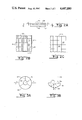
FIG. 2A is a sectional view along line B--B of FIG. 1B;
FIG. 2B is a view along line C--C of FIG. 2A;
FIG. 2C is a view along line D--D of FIG. 2A;
FIG. 3A is a view along line E--E of FIG. 1B;
FIG. 3B is a view along line F--F of FIG. 3A; and
FIG. 4 shows alternative optics for the system of FIG. 1A.
Referring now to the drawings, FIG. 1A is a schematic view in perspective of the tubular luminescence photovoltaic array system 10 of the invention, which illustrates the modular characteristic of the invention. FIG. 1B is an exploded view in perspective of system 10. FIGS. 1A, 1B illustrate the assembly of three major cooperating constituent assemblies of system 10. Light tube 11 is closed at one end and has a plurality of rectangular photovoltaic cell arrays 20 disposed on the surfaces of tube 11 along the lengthwise faces thereof; light concentrating optics 30 are operatively attached to the light receiving end of light tube 11 substantially as shown in FIGS. 1A, 1B.
Reference is now made to FIG. 1B in conjunction with FIG. 1C, a view along line A--A of FIG. 1A. Light tube 11 by itself is a substantially conventional device which converts a beam of light directed thereinto along central axis T into a radial glow, which results in the transport of light of substantially uniform intensity along length L thereof. Light tube 11 has a generally square cross section as shown in FIG. 1C and comprises four substantially identical walls 13 having smooth internal surfaces 13a defining elongated chamber 14 of square cross section. A plurality of triangular grooves defining prismatic ridges 15 of triangular cross section are formed on the outer surfaces of walls 13 and extend along the lengths thereof. Each prismatic ridge 15 defines an epex angle 15a equal to 90° and the surfaces of each ridge form an angle of 45° angle with inner surfaces 13a of light tube 11. Light tube 11 may be fabricated to substantially any desired length L and width w, may be obtained commercially, and comprises any suitable optically transparent material such as acrylic, glass, or the like. Mirror 17 having an inwardly facing reflective surface 18 thereon may be disposed at the closed end of light tube 11 opposite optics 30 as suggested in FIG. 1B, for back reflection of stray light within light tube 11.
As illustrated in FIGS. 1B, 1C, a solar cell array assembly 20 of size and rectangular shape corresponding to that of light tube 11 is disposed on each lengthwise outer surface of light tube 11. Referring additionally to FIGS. 2A, B, C, shown in FIG. 2A is a sectional view along line B--B of FIG. 1B. FIG. 2B is a view along line C--C of FIG. 2A, and FIG. 2C is a view along line D--D of FIG 2A. As shown in FIG. 2A, each solar cell array assembly 20 comprises a plurality of solar cells 21 of any convenient preselected size (usually about 2×2, 2×4, or 4×4 cm) and of any conventional type, i.e., silicon, gallium arsenide, indium phosphide, amorphous silicon, or other, and of cascade or multijunction type as would occur to the skilled artisan guided by these teachings, the same not being limiting of the invention herein, Cells 21 are supported on substrate 23 of Kapton™, Kevlar™, Kel-F™, or the like, to provide structural support and protection to cells 21 within system 10 (FIG. 1A). The back surfaces 21b of cells 21 are attached in suitable fashion to substrate 23, the active surfaces 21a facing inwardly of light tube 11 as suggested in FIG 1B. Back surfaces 21b may conventionally include electrical contacts 25, and substrate 23 may include current collecting buses 27 for connection to output 28 (FIG. 1A). Active surfaces 21a include the photovoltaic junctions 22 of cells 21. A transparent protective covering 29 of silicon dioxide, aluminum oxide, or the like may be dispersed in the array structure to cushion active surfaces 21a against prismatic ridges 15 on light tube 11. Alternatively, cushioned straps 41 may be spaced along light tube 11 (FIG. 1B) to protect the front surfaces of cells 21.
Referring now to FIGS. 3A, 3B in conjunction with FIG. 1B, shown in FIG. 3A is an end view of optics 30 along line E--E of FIG. 1B. FIG. 3B is a sectional view of FIG. 3A along line F--F. Optics 30 may comprise any suitable lens or other light collecting system for concentrating light into light tube 11 for illumination of solar cell arrays 20 in generating electricity using the invention. The representative optics 30 shown in FIGS. 1B, 3A, 3B include a parabolic reflector 31 or equivalent concave dish reflector for collecting and focusing light beam 39 toward a central focusing reflector 33 having a reflective surface 34 for concentrating light 39 into a transition element at the light receiving end of light tube 11 in the form of collimating lens 35 which substantially collimates light 39 along axis T within light tube 11. Reflector 33 may be supported at the focus of reflector 31 by a plurality of thin webs 37 as required. As light 39 transits light tube 11, prismatic ridges 15 allow light to be radiated outwardly onto arrays 20 while back reflecting the light down light tube 11 until light 39 transits length L and is back reflected by reflective surface 18 for further illumination of arrays 20.
Referring now to FIG. 4, shown therein is an alternative arrangement for the light concentrating optics of system 10 wherein a suitably sized lens system 40 is optically coupled to collimating lens 35' for concentrating light into light tube 11.
In the assembly of optics 30, light tube 11, arrays 20, and mirror 17 it may be desirable to hermetically seal system 10 and to enclose an inert gas within light tube 11 and in the voids defined between prismatic ridges 15 and covering 29 to protect cells 21 and other component parts from corrosion. Alternatively, light tube 11 and the voids may be evacuated. To the outer surfaces of assembled system 10 (FIG. 1A) may be added a suitable covering (not shown) for further protection against radiation or meteroid impact.
The photovoltaic system of the invention may be configured as a single unit or assembled in modular form of a plurality of such units to provide desirably high current output. The photovoltaic cells of the system are enclosed and substantially protected from particle impact and radiation hazards, which extends cell and array lifetime and improves overall array performance. the compactness of each modular system allows remote assembly and individual operation, presents a small target in a threat environment, minimizes the number of optical structures needed for concentration of incident light, and is therefore lighter in weight, simpler in design and more economical in structure and operation than previously known systems.
The invention, as hereinabove described, therefore provides a novel photovoltaic system for converting sunlight to electrical power. It is understood that modifications to the invention as described may be made, as might occur to one with skill in the field of this invention, within the scope of the appended claims. Therefore, all embodiments contemplated hereunder which achieve the objects of the invention have not been shown in complete detail. Other embodiments may be developed without departing from the spirit of the invention or from the scope of the appended claims.
Claims (11)
1. A photovoltaic solar cell system comprising:
(a) a hollow light tube of substantially optically transparent material, said tube having preselected length and first and second ends and including four substantially identical walls of preselected width having flat inner intersecting surfaces defining along a central axis a passageway of generally square cross section extending between said ends, said walls having on the outer surfaces thereof a plurality of triangularly shaped grooves extending along the length of said tube, said grooves defining a plurality of ridges having triangular cross section and extending along the length of said tube, said triangular cross section of each ridge having an apex angle of 90° and the surfaces of said ridges along the length of said tube defining an angle of 45° with said inner surfaces of said walls;
(b) optical means operatively connected to said first end of said tube for directing light into said tube at said first end;
(c) a plurality of solar cells each having a front photoactive surface and a back surface disposed in a rectangular array corresponding in size to the preselected width of said walls and length of said tube, said cells disposed on the outer surfaces of said walls of said tube with said front photoactive surfaces of said cells facing inwardly of said tube.
2. The system as recited in claim 1 wherein said cells are mounted on a substrate in said rectangular array.
3. The system as recited in claim 1 further comprising a cushioning layer between said front photoactive surfaces of said cells and said ridges on the outer surfaces of said tube.
4. The system as recited in claim 1 wherein said optical means includes a collimating lens at said first end of said tube and a parabolic reflector operatively connected to said collimating lens for directing light along said axis into said tube.
5. The system as recited in claim 1 wherein said optical means includes a collimating lens at said first end of said tube and a focusing lens optically aligned with said collimating lens for directing light along said axis into said tube.
6. The system as recited in claim 1 further comprising an end wall closing said second end of said tube.
7. The system as recited in claim 6 further comprising a mirrored surface on the inwardly facing surface of said end wall.
8. The system as recited in claim 6 wherein said tube, optical means and end wall are hermetically sealed and said passageway is evacuated.
9. The system as recited in claim 8 wherein said cells are hermetically sealed to said outer surfaces of said tube and the space defined between said ridges and said front photoactive surfaces of said cells is evacuated.
10. The system as recited in claim 6 wherein said tube, optical means and end wall are hermetically sealed and said passageway is filled with inert gas.
11. The system as recited in claim 10 wherein said cells are hermetically sealed to said outer surfaces of said tube and the space defined between said ridges and said front photoactive surfaces of said cells is filled with inert gas.
Priority Applications (1)
| Application Number | Priority Date | Filing Date | Title |
|---|---|---|---|
| US06/926,061 US4687880A (en) | 1986-11-03 | 1986-11-03 | Tubular luminescence photovoltaic array |
Applications Claiming Priority (1)
| Application Number | Priority Date | Filing Date | Title |
|---|---|---|---|
| US06/926,061 US4687880A (en) | 1986-11-03 | 1986-11-03 | Tubular luminescence photovoltaic array |
Publications (1)
| Publication Number | Publication Date |
|---|---|
| US4687880A true US4687880A (en) | 1987-08-18 |
Family
ID=25452685
Family Applications (1)
| Application Number | Title | Priority Date | Filing Date |
|---|---|---|---|
| US06/926,061 Expired - Fee Related US4687880A (en) | 1986-11-03 | 1986-11-03 | Tubular luminescence photovoltaic array |
Country Status (1)
| Country | Link |
|---|---|
| US (1) | US4687880A (en) |
Cited By (28)
| Publication number | Priority date | Publication date | Assignee | Title |
|---|---|---|---|---|
| US5374317A (en) | 1990-09-26 | 1994-12-20 | Energy Systems Solar, Incorporated | Multiple reflector concentrator solar electric power system |
| WO1996011501A1 (en) * | 1994-10-09 | 1996-04-18 | Yeda Research And Development Co. Ltd. | Photovoltaic cell system and an optical structure therefore |
| US6020553A (en) * | 1994-10-09 | 2000-02-01 | Yeda Research And Development Co., Ltd. | Photovoltaic cell system and an optical structure therefor |
| US20070240758A1 (en) * | 2006-04-14 | 2007-10-18 | Thomas Spartz | Double-sided solar module |
| US20080083449A1 (en) * | 2006-10-06 | 2008-04-10 | Solyndra, Inc., A Delaware Corporation | Sealed photovoltaic apparatus |
| US20100132794A1 (en) * | 2006-10-06 | 2010-06-03 | Cumpston Brian H | Sealed photovoltaic apparatus |
| US20100252030A1 (en) * | 2009-04-01 | 2010-10-07 | Abengoa Solar Inc. | Torque transfer between trough collector modules |
| US20110146757A1 (en) * | 2009-12-18 | 2011-06-23 | Rider Christopher B | Luminescent solar concentrator |
| CN101795089B (en) * | 2009-12-29 | 2012-06-27 | 奇瑞汽车股份有限公司 | Solar lighting generation device and preparation method thereof |
| US20120279554A1 (en) * | 2011-05-02 | 2012-11-08 | Paul Alan Bostwick | Hybrid solar systems and methods of manufacturing |
| US8430093B1 (en) * | 2009-05-27 | 2013-04-30 | Lockheed Martin Corporation | Solar collector using subreflector |
| CN103427712A (en) * | 2012-05-22 | 2013-12-04 | 周登荣 | Improved solar generating set |
| CN103457512A (en) * | 2013-07-22 | 2013-12-18 | 刘庆云 | Application method of tubular photovoltaic power generation assembly |
| US8615960B2 (en) | 2009-07-24 | 2013-12-31 | Abengoa Solar Inc. | Solar collector module |
| EP2692644A1 (en) * | 2011-03-29 | 2014-02-05 | Mitsubishi Heavy Industries, Ltd. | Spacecraft |
| US20160056316A1 (en) * | 2014-08-25 | 2016-02-25 | Daniel S. Clark | Three Dimensional Photovoltaic Module |
| EP2993705A1 (en) * | 2014-09-05 | 2016-03-09 | Airbus Defence and Space GmbH | Solarconcentrator for high altitude flying light-weight structure |
| US20160376037A1 (en) | 2014-05-14 | 2016-12-29 | California Institute Of Technology | Large-Scale Space-Based Solar Power Station: Packaging, Deployment and Stabilization of Lightweight Structures |
| US9893223B2 (en) | 2010-11-16 | 2018-02-13 | Suncore Photovoltaics, Inc. | Solar electricity generation system |
| US10454565B2 (en) | 2015-08-10 | 2019-10-22 | California Institute Of Technology | Systems and methods for performing shape estimation using sun sensors in large-scale space-based solar power stations |
| EP3591720A1 (en) * | 2018-07-02 | 2020-01-08 | Suk Man Bae | Solar power generation unit and system |
| US10696428B2 (en) | 2015-07-22 | 2020-06-30 | California Institute Of Technology | Large-area structures for compact packaging |
| US10992253B2 (en) | 2015-08-10 | 2021-04-27 | California Institute Of Technology | Compactable power generation arrays |
| US11128179B2 (en) | 2014-05-14 | 2021-09-21 | California Institute Of Technology | Large-scale space-based solar power station: power transmission using steerable beams |
| US11362228B2 (en) | 2014-06-02 | 2022-06-14 | California Institute Of Technology | Large-scale space-based solar power station: efficient power generation tiles |
| US11626526B2 (en) * | 2014-08-25 | 2023-04-11 | Daniel S. Clark | 3D printed three-dimensional photovoltaic module |
| US11634240B2 (en) | 2018-07-17 | 2023-04-25 | California Institute Of Technology | Coilable thin-walled longerons and coilable structures implementing longerons and methods for their manufacture and coiling |
| US11772826B2 (en) | 2018-10-31 | 2023-10-03 | California Institute Of Technology | Actively controlled spacecraft deployment mechanism |
Citations (10)
| Publication number | Priority date | Publication date | Assignee | Title |
|---|---|---|---|---|
| US30584A (en) * | 1860-11-06 | Improved device for sustaining trees | ||
| US247229A (en) * | 1880-12-10 | 1881-09-20 | Apparatus for lighting dwellings or other structures | |
| US2506625A (en) * | 1946-07-08 | 1950-05-09 | Harold W Woolley | Photoelectric cell |
| US3565719A (en) * | 1967-05-17 | 1971-02-23 | Nasa | Solar panel fabrication |
| US3976508A (en) * | 1974-11-01 | 1976-08-24 | Mobil Tyco Solar Energy Corporation | Tubular solar cell devices |
| US3990914A (en) * | 1974-09-03 | 1976-11-09 | Sensor Technology, Inc. | Tubular solar cell |
| US4026267A (en) * | 1975-12-11 | 1977-05-31 | Coleman Rich F | Solar energy apparatus |
| US4304955A (en) * | 1978-03-14 | 1981-12-08 | Energy Integrated Systems, Inc. | Solar energy collector |
| US4519384A (en) * | 1984-05-14 | 1985-05-28 | Murtha R Michael | Concentrating solar beam collector |
| US4529830A (en) * | 1980-08-18 | 1985-07-16 | Maurice Daniel | Apparatus for collecting, distributing and utilizing solar radiation |
-
1986
- 1986-11-03 US US06/926,061 patent/US4687880A/en not_active Expired - Fee Related
Patent Citations (10)
| Publication number | Priority date | Publication date | Assignee | Title |
|---|---|---|---|---|
| US30584A (en) * | 1860-11-06 | Improved device for sustaining trees | ||
| US247229A (en) * | 1880-12-10 | 1881-09-20 | Apparatus for lighting dwellings or other structures | |
| US2506625A (en) * | 1946-07-08 | 1950-05-09 | Harold W Woolley | Photoelectric cell |
| US3565719A (en) * | 1967-05-17 | 1971-02-23 | Nasa | Solar panel fabrication |
| US3990914A (en) * | 1974-09-03 | 1976-11-09 | Sensor Technology, Inc. | Tubular solar cell |
| US3976508A (en) * | 1974-11-01 | 1976-08-24 | Mobil Tyco Solar Energy Corporation | Tubular solar cell devices |
| US4026267A (en) * | 1975-12-11 | 1977-05-31 | Coleman Rich F | Solar energy apparatus |
| US4304955A (en) * | 1978-03-14 | 1981-12-08 | Energy Integrated Systems, Inc. | Solar energy collector |
| US4529830A (en) * | 1980-08-18 | 1985-07-16 | Maurice Daniel | Apparatus for collecting, distributing and utilizing solar radiation |
| US4519384A (en) * | 1984-05-14 | 1985-05-28 | Murtha R Michael | Concentrating solar beam collector |
Non-Patent Citations (2)
| Title |
|---|
| "Crosscurrents", Science 86, 4, 72 (Apr. 1986). |
| Crosscurrents , Science 86, 4, 72 (Apr. 1986). * |
Cited By (46)
| Publication number | Priority date | Publication date | Assignee | Title |
|---|---|---|---|---|
| US5374317A (en) | 1990-09-26 | 1994-12-20 | Energy Systems Solar, Incorporated | Multiple reflector concentrator solar electric power system |
| WO1996011501A1 (en) * | 1994-10-09 | 1996-04-18 | Yeda Research And Development Co. Ltd. | Photovoltaic cell system and an optical structure therefore |
| US6020553A (en) * | 1994-10-09 | 2000-02-01 | Yeda Research And Development Co., Ltd. | Photovoltaic cell system and an optical structure therefor |
| US20070240758A1 (en) * | 2006-04-14 | 2007-10-18 | Thomas Spartz | Double-sided solar module |
| WO2007120856A2 (en) * | 2006-04-14 | 2007-10-25 | Thomas Spartz | Double-sided solar module |
| WO2007120856A3 (en) * | 2006-04-14 | 2008-10-16 | Thomas Spartz | Double-sided solar module |
| US20080083449A1 (en) * | 2006-10-06 | 2008-04-10 | Solyndra, Inc., A Delaware Corporation | Sealed photovoltaic apparatus |
| US20100132794A1 (en) * | 2006-10-06 | 2010-06-03 | Cumpston Brian H | Sealed photovoltaic apparatus |
| US20100252030A1 (en) * | 2009-04-01 | 2010-10-07 | Abengoa Solar Inc. | Torque transfer between trough collector modules |
| US8844519B2 (en) | 2009-04-01 | 2014-09-30 | Abengoa Solar Llc | Torque transfer between trough collector modules |
| US8322333B2 (en) * | 2009-04-01 | 2012-12-04 | Abengoa Solar Inc. | Torque transfer between trough collector modules |
| US8430093B1 (en) * | 2009-05-27 | 2013-04-30 | Lockheed Martin Corporation | Solar collector using subreflector |
| US8615960B2 (en) | 2009-07-24 | 2013-12-31 | Abengoa Solar Inc. | Solar collector module |
| US9057543B2 (en) | 2009-07-24 | 2015-06-16 | Abengoa Solar Llc | Solar collector module |
| US9778447B2 (en) | 2009-12-18 | 2017-10-03 | Eastman Kodak Company | Luminescent solar concentrator |
| US8889983B2 (en) | 2009-12-18 | 2014-11-18 | Eastman Kodak Company | Luminescent solar concentrator |
| US20110146757A1 (en) * | 2009-12-18 | 2011-06-23 | Rider Christopher B | Luminescent solar concentrator |
| CN101795089B (en) * | 2009-12-29 | 2012-06-27 | 奇瑞汽车股份有限公司 | Solar lighting generation device and preparation method thereof |
| US9893223B2 (en) | 2010-11-16 | 2018-02-13 | Suncore Photovoltaics, Inc. | Solar electricity generation system |
| US9293620B2 (en) | 2011-03-29 | 2016-03-22 | Mitsubishi Heavy Industries, Ltd. | Space machine |
| EP2692644A1 (en) * | 2011-03-29 | 2014-02-05 | Mitsubishi Heavy Industries, Ltd. | Spacecraft |
| EP2692644A4 (en) * | 2011-03-29 | 2014-09-24 | Mitsubishi Heavy Ind Ltd | Spacecraft |
| US20120279554A1 (en) * | 2011-05-02 | 2012-11-08 | Paul Alan Bostwick | Hybrid solar systems and methods of manufacturing |
| CN103427712B (en) * | 2012-05-22 | 2015-10-28 | 周登荣 | A kind of device of solar generating of improvement |
| CN103427712A (en) * | 2012-05-22 | 2013-12-04 | 周登荣 | Improved solar generating set |
| CN103457512B (en) * | 2013-07-22 | 2017-08-15 | 刘庆云 | A kind of tubular photovoltaic electrification component application process |
| CN103457512A (en) * | 2013-07-22 | 2013-12-18 | 刘庆云 | Application method of tubular photovoltaic power generation assembly |
| US20160376037A1 (en) | 2014-05-14 | 2016-12-29 | California Institute Of Technology | Large-Scale Space-Based Solar Power Station: Packaging, Deployment and Stabilization of Lightweight Structures |
| US11128179B2 (en) | 2014-05-14 | 2021-09-21 | California Institute Of Technology | Large-scale space-based solar power station: power transmission using steerable beams |
| US10144533B2 (en) | 2014-05-14 | 2018-12-04 | California Institute Of Technology | Large-scale space-based solar power station: multi-scale modular space power |
| US10340698B2 (en) | 2014-05-14 | 2019-07-02 | California Institute Of Technology | Large-scale space-based solar power station: packaging, deployment and stabilization of lightweight structures |
| US11362228B2 (en) | 2014-06-02 | 2022-06-14 | California Institute Of Technology | Large-scale space-based solar power station: efficient power generation tiles |
| US20160056316A1 (en) * | 2014-08-25 | 2016-02-25 | Daniel S. Clark | Three Dimensional Photovoltaic Module |
| US9899956B2 (en) * | 2014-08-25 | 2018-02-20 | Daniel S Clark | 3D printed solar energy |
| US11626526B2 (en) * | 2014-08-25 | 2023-04-11 | Daniel S. Clark | 3D printed three-dimensional photovoltaic module |
| WO2016034667A1 (en) * | 2014-09-05 | 2016-03-10 | Airbus Defence and Space GmbH | Solar concentrator for high-flying lightweight structure |
| EP2993705A1 (en) * | 2014-09-05 | 2016-03-09 | Airbus Defence and Space GmbH | Solarconcentrator for high altitude flying light-weight structure |
| US10696428B2 (en) | 2015-07-22 | 2020-06-30 | California Institute Of Technology | Large-area structures for compact packaging |
| US10454565B2 (en) | 2015-08-10 | 2019-10-22 | California Institute Of Technology | Systems and methods for performing shape estimation using sun sensors in large-scale space-based solar power stations |
| US10992253B2 (en) | 2015-08-10 | 2021-04-27 | California Institute Of Technology | Compactable power generation arrays |
| US10749593B2 (en) | 2015-08-10 | 2020-08-18 | California Institute Of Technology | Systems and methods for controlling supply voltages of stacked power amplifiers |
| US11038073B2 (en) | 2018-07-02 | 2021-06-15 | Suk Man BAE | Solar power generation unit and system |
| JP2020010032A (en) * | 2018-07-02 | 2020-01-16 | 錫晩 ▲裴▼ | Solar power generation unit and system of the same |
| EP3591720A1 (en) * | 2018-07-02 | 2020-01-08 | Suk Man Bae | Solar power generation unit and system |
| US11634240B2 (en) | 2018-07-17 | 2023-04-25 | California Institute Of Technology | Coilable thin-walled longerons and coilable structures implementing longerons and methods for their manufacture and coiling |
| US11772826B2 (en) | 2018-10-31 | 2023-10-03 | California Institute Of Technology | Actively controlled spacecraft deployment mechanism |
Similar Documents
| Publication | Publication Date | Title |
|---|---|---|
| US4687880A (en) | Tubular luminescence photovoltaic array | |
| US7619159B1 (en) | Integrating sphere photovoltaic receiver (powersphere) for laser light to electric power conversion | |
| US6118067A (en) | Method and apparatus for improved solar concentration arrays | |
| EP0848432B1 (en) | High efficieny tandem solar cells | |
| US6057505A (en) | Space concentrator for advanced solar cells | |
| US5154777A (en) | Advanced survivable space solar power system | |
| US3427200A (en) | Light concentrator type photovoltaic panel having clamping means for retaining photovoltaic cell | |
| Landis | Photovoltaic receivers for laser beamed power in space | |
| US20130099599A1 (en) | Thermally Efficient Power Conversion Modules for Space Solar Power | |
| US4324946A (en) | Solar radiation concentrator | |
| JP3432497B2 (en) | Integrated circuit micro satellite | |
| US20130146121A1 (en) | Solar light concentration photovoltaic conversion system using a wavelength splitter and lambda-specific photovoltaic cells optically coupled to lambda-dedicated fibers illuminated by respective split beams | |
| Landis | Moonbase night power by laser illumination | |
| Schultz et al. | Imaging planets about other stars with UMBRAS | |
| US20220360213A1 (en) | Low Specific Mass Space Power System | |
| US5979834A (en) | Spacecraft solar power system | |
| Nakagawa et al. | HII/L2 mission: future Japanese infrared astronomical mission | |
| US5086828A (en) | Lunar radiator shade | |
| Ortabasi et al. | PowerSphere: A novel photovoltaic cavity converter using low bandgap TPV cells for efficient conversion of high power laser beams to electricity | |
| Goldsmith et al. | CALISTO: The cryogenic aperture large infrared space telescope observatory | |
| Zhang et al. | Generation-X: a large aperture, high angular resolution x-ray observatory for the 2010's | |
| LANDIS | Space power by ground-based laser transmission | |
| PATTERSON | Study of multi-kilowatt solar arrays for Earth orbit applications[Final Report, 19 Nov. 1980- 30 Jun. 1983] | |
| Scheffer | Large scale use of solar power may be visible across interstellar distances | |
| Landis | Space power by laser illumination of PV arrays |
Legal Events
| Date | Code | Title | Description |
|---|---|---|---|
| AS | Assignment |
Owner name: UNITED STATES OF AMERICA, THE, AS REPRESENTED BY T Free format text: ASSIGNMENT OF ASSIGNORS INTEREST.;ASSIGNOR:MORRIS, ROBERT K.;REEL/FRAME:004684/0257 Effective date: 19861023 |
|
| REMI | Maintenance fee reminder mailed | ||
| FPAY | Fee payment |
Year of fee payment: 4 |
|
| SULP | Surcharge for late payment | ||
| REMI | Maintenance fee reminder mailed | ||
| LAPS | Lapse for failure to pay maintenance fees | ||
| FP | Lapsed due to failure to pay maintenance fee |
Effective date: 19950823 |
|
| STCH | Information on status: patent discontinuation |
Free format text: PATENT EXPIRED DUE TO NONPAYMENT OF MAINTENANCE FEES UNDER 37 CFR 1.362 |