US4710972A - SHF receiver - Google Patents

SHF receiver Download PDF

Info

Publication number
US4710972A
US4710972A US06/914,305 US91430586A US4710972A US 4710972 A US4710972 A US 4710972A US 91430586 A US91430586 A US 91430586A US 4710972 A US4710972 A US 4710972A
Authority
US
United States
Prior art keywords
channels
polarization
plane
satellite broadcast
channel
Prior art date
Legal status (The legal status is an assumption and is not a legal conclusion. Google has not performed a legal analysis and makes no representation as to the accuracy of the status listed.)
Expired - Lifetime
Application number
US06/914,305
Inventor
Toshihide Hayashi
Osamu Yamakami
Ikuo Kanayama
Current Assignee (The listed assignees may be inaccurate. Google has not performed a legal analysis and makes no representation or warranty as to the accuracy of the list.)
Sony Corp
Original Assignee
Sony Corp
Priority date (The priority date is an assumption and is not a legal conclusion. Google has not performed a legal analysis and makes no representation as to the accuracy of the date listed.)
Filing date
Publication date
Application filed by Sony Corp filed Critical Sony Corp
Assigned to SONY CORPORATION, A CORP OF JAPAN reassignment SONY CORPORATION, A CORP OF JAPAN ASSIGNMENT OF ASSIGNORS INTEREST. Assignors: HAYASHI, TOSHIHIDE, KANAYAMA, IKUO, YAMAKAMI, OSAMU
Application granted granted Critical
Publication of US4710972A publication Critical patent/US4710972A/en
Anticipated expiration legal-status Critical
Expired - Lifetime legal-status Critical Current

Links

Images

Classifications

    • HELECTRICITY
    • H04ELECTRIC COMMUNICATION TECHNIQUE
    • H04BTRANSMISSION
    • H04B1/00Details of transmission systems, not covered by a single one of groups H04B3/00 - H04B13/00; Details of transmission systems not characterised by the medium used for transmission
    • H04B1/06Receivers
    • H04B1/10Means associated with receiver for limiting or suppressing noise or interference
    • H04B1/1009Placing the antenna at a place where the noise level is low and using a noise-free transmission line between the antenna and the receivers
    • HELECTRICITY
    • H01ELECTRIC ELEMENTS
    • H01QANTENNAS, i.e. RADIO AERIALS
    • H01Q21/00Antenna arrays or systems
    • H01Q21/24Combinations of antenna units polarised in different directions for transmitting or receiving circularly and elliptically polarised waves or waves linearly polarised in any direction
    • H01Q21/245Combinations of antenna units polarised in different directions for transmitting or receiving circularly and elliptically polarised waves or waves linearly polarised in any direction provided with means for varying the polarisation 
    • HELECTRICITY
    • H04ELECTRIC COMMUNICATION TECHNIQUE
    • H04BTRANSMISSION
    • H04B1/00Details of transmission systems, not covered by a single one of groups H04B3/00 - H04B13/00; Details of transmission systems not characterised by the medium used for transmission
    • H04B1/06Receivers
    • H04B1/16Circuits
    • H04B1/18Input circuits, e.g. for coupling to an antenna or a transmission line

Definitions

  • This invention relates generally to a superhigh frequency (SHF) receiver, and more particularly is directed to an SHF receiver which can receive satellite broadcast signals having different planes of polarization for adjacent channels.
  • SHF superhigh frequency
  • the frequency spacing between adjacent channels is smaller than such band width, for example, is about 20 MHz, as shown on FIG. 1. Accordingly, in order to avoid radio interference between adjacent channels, it is known to make the planes of polarization of the satellite broadcast signals different for adjacent channels. By way of example, use has been made of a horizontal polarized wave and a vertical polarized wave, or a clockwise circular polarized wave and a counter-clockwise circular polarized wave, and so on.
  • an SHF receiver which receives satellite broadcast signals having different planes of polarization for adjacent channels
  • the channel selection is carried out in the sequential order of channel 1, channel 2, channel 3 . . . etc.
  • the receiving plane of polarization of a polarizer is automatically changed-over so that the channel selection speed is necessarily slow.
  • the other alternate channels for example, the even-numbered channels
  • the user has to manually change-over the receiving plane of polarization of the polarizer and this is very bothersome for the user.
  • an apparatus for receiving satellite broadcast signals having a first plane of polarization for alternate first channels and a second plane of polarization for the second channels therebetween comprises: antenna means for receiving said satellite broadcast signals; polarizer means for receiving a satellite broadcast signal derived from said antenna means and having a plane of polarization adapted to be switched for correspondence with the plane of polarization of the received satellite broadcast signal; channel selecting means for continuously selecting the channels of said satellite broadcast signals; means for tuning to a channel selected by said channel selecting means; and controlling means for controlling the tuning of said tuning means and the switching of the plane of polarization of said polarizer means in accordance with a channel selected by said channel selecting means, said controlling means causing said tuning means to tune first to every other channel, that is, alternate channels having the same plane of polarization, in series, and thereafter switching the plane of polarization of said polarizer means and causing tuning in series to the other alternate channels all having another plane of polarization.
  • FIG. 1 is a schematic representation to which reference is made in explaining the necessity of the switching of the planes of polarization
  • FIG. 2 is a block diagram broadly showing the principle of the present invention
  • FIG. 3 (formed of FIGS. 3-I and 3-II) is a block diagram showing a satellite broadcasting receiver according to an embodiment of the present invention
  • FIG. 4 is schematic representation showing a format of a satellite broadcast signal
  • FIGS. 5A to 5D are diagrams showing the positions of carrier waves of FM audio signals for respective modes.
  • FIG. 6 is a flow chart to which reference will be made in explaining the operation of the SHF receiver according to the invention in selecting the channels in sequence.
  • a SHF receiver is shown to comprise a receiving unit 1 for receiving satellite broadcast signals having different planes of polarization (for example, horizontal and vertical planes of polarization) for the adjacent channels, a switching unit 2 for changing-over the receiving plane of polarization of the receiving unit 1, and a controller, for example, a micro-computer 3, for controlling the operations of the receiving unit 1 and the switching unit 2.
  • receiving unit 1 sequentially selects every other channel, for example, the odd-numbered channels, whose satellite broadcast signals have a first polarization plane.
  • the switching unit 2 changes-over the receiving polarization plane from the first polarization plane to a second polarization plane and, thereafter, the receiving unit 1 sequentially selects the remaining alternate channels, for example, the even-numbered channels, whose satellite broadcast signals have the second plane of polarization.
  • the receiving plane of polarization is switched and then the other alternate channels whose satellite broadcast signals have the second plane of polarization are sequentially selected.
  • the receiving plane of polarization is switched only once. Further, such switching of the receiving plane of polarization can be easily effected automatically.
  • FIG. 3 formed of FIGS. 3-I and 3-II on two sheets of drawings so as to be of sufficiently large scale.
  • a satellite broadcast signal S BS of the ku band (12 GHz band ranging from 11.7 to 12.2 GHz) or the c band (4 GHz band ranging from 3.7 to 4.2 GHz) is transmitted from a broadcasting satellite 10 and supplied through a BS antenna 11 to a polarizer 12a.
  • This polarizer 12a may be of a well known type, for example, as is disclosed in U.S. Pat. No. 4,414,516.
  • the satellite broadcast signal S BS received by polarizer 12a is supplied to a super-high frequency/ultra-high frequency (S/U) converter 12b.
  • S/U converter 12b the satellite broadcast signal S BS is frequency-converted to a signal S BS , having a frequency of 950 to 1450 MHz with respect to both the ku band and the c band.
  • a local frequency suitably provided in the S/U converter 12b for frequency conversion is selectively provided with a frequency of 10.75 GHz for the ku band or with a frequency of 2.75 GHz for the c band.
  • FIG. 3 shows a single system comprised of the BS antenna 11 and the S/U converter 12b, in practice, for the reception of the ku band and the c band, different respective systems, each formed of a BS antenna and an S/U converter, may be employed with a suitable arrangement being provided for selecting one system or the other and providing the respective local frequency.
  • the satellite broadcast signal S BS is a signal in which a video signal Sv, whose highest frequency is 4.2 MHz, is frequency-multiplexed with an FM audio signal S AFM whose carrier wave is in a frequency band above the highest frequency of this video signal Sv, for example, in a 5 to 8.5 MHz band, and the carrier wave of 12 GHz or 4 GHz for the ku band or the c band, respectively, is frequency-modulated by the signals Sv and S AFM .
  • the signal S BS is also an FM signal.
  • the satellite broadcast signal S BS can have any one of 4 audio modes, such as, (1) a monaural mode; (2) a multiplex mode; (3) a discrete mode; and (4) a matrix mode.
  • the FM audio signal S AFM in the case of the monaural mode is a monaural audio signal S A which results from frequency-modulating a single carrier wave of 5 to 8.5 MHz.
  • the frequency deviation thereof is suitably selected, for example, as 75 kHz.
  • the FM audio signal S AFM in the case of the multiplex mode is a composed signal which results from mixing a sum signal (L+R) of a left audio signal L and a right audio signal R and a signal which results from frequency-modulating a single sub-carrier by a difference signal (L-R).
  • the single carrier wave to be frequency modulated again has a frequency in the 5 to 8.5 MHz band, and its frequency deviation is suitably selected, for example, as 100 kHz.
  • the FM audio signal S AFM in the case of the discrete mode is formed by frequency-modulating first and second carrier waves of 5 to 8.5 MHz band by the left audio signal L and the right audio signal R, respectively.
  • the frequency deviation of each carrier wave is suitably selected, for example, as 75 kHz. In this case, the spacing between the frequencies of the first and second carrier waves is selected, for example, as 0.18 MHz.
  • the FM audio signal S AFM in the case of the matrix mode results from frequency-modulating first and second carrier waves in the 5 to 8.5 MHz band by the sum signal (L+R) and the difference signal (L-R), respectively.
  • the frequency deviation of each carrier wave is suitably selected, for example, as 100 kHz. In this case, the spacing between the first and second carrier waves is frequently selected to be 1.00 MHz.
  • the positions of the carrier waves in the FM audio signal S AFM are not standardized for the several modes, and thus they may be placed at any given positions in the range from 5.0 to 8.5 MHz.
  • the positions at which the carrier waves are placed most frequently will be indicated below with reference to FIGS. 5A to 5D, respectively.
  • the single carrier wave is positioned at 6.80 MHz; in the case of the discrete mode (FIG. 5C), the carrier waves are positioned at 5.58 MHz and 5.76 MHz; and, in the case of the matrix mode (FIG. 5D), the carrier waves are positioned at 5.80 MHz and 6.80 MHz.
  • the number of channels available for the ku band and the c band is 24 channels.
  • the planes of polarization of the satellite broadcast signals for the respective channels are made different for the adjacent channels.
  • the odd-numbered channels, such as channels 1,3, . . . ,23 have horizontal planes of polarization
  • the even-numbered channels, such as, channels 2,4, . . . ,24 have vertical planes of polarization, respectively.
  • the foregoing ensures that although the necessary band width per channel is, for example, 27 MHz, and the frequency spacing between the adjacent channels is only about 20 MHz, as shown on FIG. 1, radio interference between the adjacent channels will be avoided.
  • the signal S BS' from S/U converter 12b is supplied through a terminal 13 to a signal processor 14 provided in a receiver 100.
  • the signal S BS' having a frequency ranging from 950 to 1450 MHz is converted to an intermediate frequency signal having a frequency of, for example, 402.78 MHz, and then FM-demodulated and thereby delivered as a mixed signal S O which is formed of the video signal Sv and the FM audio signal S AFM shown in FIG. 4.
  • the received channel is selected by changing a local signal S L supplied to processor 14 from a PLL (phase locked loop) circuit 15 for frequency conversion of the signal S BS' .
  • the PLL circuit 15 is controlled by a micro-computer 17 in response to the user's manipulation of an operation panel 16. More particularly, the frequency dividing ratio of a frequency divider (not shown) contained in the PLL circuit 15 may be controlled to determine the channel selected.
  • a signal S AFT indicative of any change of the intermediate frequency is supplied from signal processor 14 to micro-computer 17 so that an AFT (automatic fine tuning) operation may be carried out for maintaining the intermediate frequency at 402.78 MHz.
  • the received channel may be selected at random by suitable actuation of a key-pad comprised of ten keys [1] to [0] provided on operation panel 16, or the channel selection may be effected in sequence by actuation of an up-key 161 or a down-key 162 on operation panel 16.
  • the user inputs the numeral corresponding to the desired channel by suitably depressing one or more of the ten keys [1] to [0] on operational panel 16 and then depressing an enter key [ENTER].
  • the dividing ratio of the frequency divider contained in PLL circuit 15 is changed by micro-computer 17 so that the resulting changed frequency of the local signal S L from PLL circuit 15 is suitable for selecting or tuning to the desired channel.
  • the plane of polarization of the satellite broadcast signal S BS is either a horizontal or vertical plane of polarization in dependence on the channel. Accordingly, when the received channel is changed, the reception plane of polarization established by polarizer 12a must be matched with the new received channel.
  • a key 163 on operation panel 16 is actuated to change-over the reception plane of polarization. More specifically, the state of a switching signal S PO supplied from micro-computer 17 through an amplifier 18 to a terminal 19 and used to control polarizer 12a to change-over the reception plane of polarization is alternated or changed by successive operations of key 163, thus changing-over the reception plane of polarization established by polarizer 12a.
  • the user depresses up-key 161 or down-key 162 provided on operation panel 16.
  • the dividing ratio of the frequency divider (not shown) contained in PLL circuit 15 is sequentially changed by micro-computer 17 so that the frequency of local signal S L from PLL circuit 15 is sequentially changed, and hence the received channel is changed in sequence so long as key 161 or 162 is depressed.
  • the received channel is changed in the order of 1,3, . . . 23,2,4, 24,1,3, . . .
  • down-key 162 is depressed, the received channel is changed in the order of 23,21, . . . ,1,24,22, . .
  • the received channel is selected from the odd channels in sequence and then from the even channels in sequence, alternately.
  • the plane of polarization for each odd channel is horizontal and the plane of polarization for each even channel is vertical so that when the selection is changed from among the even channels to among the odd channels, or from among the odd channels, to among the even channels, the reception plane of polarization is suitably changed.
  • the state of switching signal S PO derived from micro-computer 17 is automatically changed for changing-over the reception plane of polarization only when the channel selection changes from among the odd- or even-numbered channels to among the even-or odd-numbered channels, respectively.
  • step A it is determined or decided if either the up-key 161 or the down-key 162 is depressed. If the answer to decision step A is "NO", that step is iterated. If one of the keys 161 and 162 is depressed, the program goes to step 1 or step 9. If up-key 161 is depressed at step 1, "2" is added to the channel number CH at step 2. Then, the program goes to step 3 at which it is determined whether the channel number CH is at least equal to "25", that is, "25” or more.
  • step 4 the program immediately goes to step 4 at which the channel corresponding to the channel number CH is selected.
  • step 3 the program goes from step 5.
  • step 5 it is determined whether the channel number CH is even or odd. If the channel number is odd, the program goes to step 6 at which the channel number "2" is selected. On the other hand, if the channel number is even, the program goes to step 7 at which the channel number CH "1" is selected. From step 6 or step 7, the program goes to step 8.
  • step 8 the reception plane of polarization is suitably switched and then the channel corresponding to the channel number CH is selected at step 4.
  • step 4 the program returns to step A which again decides if either of keys 161 and 162 is depressed. So long as the up-key 161 is depressed, the above mentioned operations are repeatedly executed. When the up-key 161 is released, the reception channel number existing at that time is ultimately selected.
  • step 10 When the down-key 162 is depressed at step 9, the program goes to step 10 at which "2" is subtracted from the channel number CH. Then, the program goes to step 11 at which it is decided whether the channel number CH is equal to or less than "0". If the channel number CH is not equal to or less than "0", the program goes to step 4. At step 4, the channel corresponding to the channel number CH is selected. On the other hand, if the channel number CH is equal to or less than "0”, the program goes to step 12 at which it is decided whether the channel number CH is even or odd. If the channel number CH is odd, the channel number "24" is selected at step 13. On the other hand, if the channel number is even, the channel number "23" is selected at step 14.
  • step 13 or 14 the reception plane of polarization is switched at step 8 and the channel corresponding to the channel number CH is selected at step 4 and the program returns to step A. So long as the down-key 162 is depressed, the above mentioned operations are repeatedly executed. When the down-key 162 is released, the reception channel number existing at that time is ultimately selected.
  • a display section 201 of a display panel 20 displays the channel number of the received channel.
  • channel number "6" is selected.
  • a display section 202 (H) or a display section 203 (V), respectively is illuminated on display panel 20.
  • a display section 204 on display panel 20 is illuminated when a satellite broadcast signal is received.
  • a display section 205 on display panel 20 is illuminated when the received satellite broadcast signal is of a predetermined one of the bands, for example, the ku band or the c band.
  • the mixed signal S O (FIG. 4) derived from signal processor 14 is supplied to a de-emphasis circuit 21 in which the signal, which had undergone a pre-emphasis at the transmission side, is de-emphasized or re-converted to the original signal.
  • the output signal from de-emphasis circuit 21 is supplied to a low pass filter 22 from which the video signal S V is derived.
  • This video signal S V is amplified by an amplifier 23 and then supplied to an energy dispersal signal eliminating circuit 24.
  • an energy dispersal signal which consists of a triangular wave superimposed upon the video signal S V at the transmission side, is removed from video signal S V , and signal S V from circuit 24 is delivered through a muting circuit 25 to an output terminal 26.
  • the muting circuit 25 is controlled by a muting control signal S MV which is formed by signal processor 14 in response to the existence or non-existence of the carrier wave of the intermediate frequency of 402.78 MHz. When the carrier wave with the intermediate frequency of 402.78 is absent, muting circuit 25 is made operative, that is, placed in the muting state.
  • the mixed signal S O derived from signal processor 14 is also supplied to a band pass filter 30 from which there is derived the FM audio signal S AFM having a carrier wave in the 5.0 to 8.5 MHz band.
  • This FM audio signal S AFM is supplied to PLL circuits 31 and 32, each of which includes a mixer and a frequency converter (not shown). These PLL circuits 31 and 32 are used to convert a carrier wave of the FM audio signal S AFM to a wave with the frequency of 10.7 MHz.
  • the selected audio mode is the monaural mode or the multiplex mode
  • a single carrier wave in the 5.0 to 8.5 MHz band is used, and the converted output is derived from, for example, the PLL circuit 31.
  • the selected audio mode is the discrete mode or the matrix mode
  • first and second carrier waves in the 5.0 to 8.5 MHz band are used as described above, so that the converted outputs are derived from both the PLL circuits 31 and 32.
  • the carrier waves may be placed at any positions within 5.0 to 8.5 MHz band. Therefore, in order to receive a desired FM audio signal S AFM , that is, in order to convert the carrier wave of the FM audio signal S AFM to an intermediate frequency signal of 10.7 MHz, on the basis of the user's operation of keys on the operation panel 16, suitable frequency dividing ratio control signals SN1 and SN2 are supplied to PLL circuits 31 aand 32, respectively, from micro-computer 17 and the frequency dividing ratios of frequency dividers (not shown) contained in the PLL circuits 31 and 32 are correspondingly controlled so as to carry out the so-called tuning.
  • the frequencies of the carrier waves of the FM audio signal S AFM for the several audio modes may be selected freely in a range from 5.0 to 8.5 MHz.
  • the carrier waves are frequently given a frequency of 6.80 MHz; in the case of the discrete mode, the carriers are frequently given the frequencies of 5.58 MHz and 5.76 MHz; and, in the case of the matrix mode, the carriers are frequently given the frequencies 5.80 MHz and 6.80 MHz.
  • a key 164 is provided on the operation panel 16 and may be depressed to select the audio mode.
  • the audio mode is changed in the sequential order of monaural mode, multiplex mode, discrete mode, matrix mode, monaural mode, . . .
  • tuning is automatically carried out so that they tuning frequency f1 in PLL circuit 31 becomes 6.80 MHz.
  • tuning is automatically carried out so that the tuning frequencies f1 and f2 of PLL circuits 31 and 32 become 5.58 MHz and 5.76 MHz, respectively.
  • tuning is automatically carried out so that the tuning frequencies f1 and f2 of PLL circuits 31 and 32 become 5.80 MHz and 6.80 MHz, respectively.
  • the selected audio mode is displayed, for example, selection of the monaural, multiplex, discrete and matrix modes is indicated or displayed by selective illumination of display sections 206,207,208 and 209, respectively, on display panel 20.
  • the tuning frequencies of the PLL circuits 31 and 32 are selected to have the predetermined values.
  • tuning can be nevertheless carried out by the user operating keys on the operation panel 16. For example, after an audio tuning key 165 on operation panel 16 is depressed, the ten keys [1] to [0] or the up-key 161 or the down-key 162 may be sued to select the tuning frequencies.
  • an audio signal S A1 derived from PLL circuit 31 and having the carrier wave of 10.7 MHz is supplied through a band pass filter 33 with a narrow pass band and also through a band pass filter 34 with a wide pass band to fixed contacts A and B, respectively, of a change-over switch 35.
  • an audio signal S A2 having a carrier wave of 10.7 MHz and derived from the PLL circuit 32 is supplied through a band pass filter 36 with a narrow pass band and a band pass filter 37 with a wide pass band to fixed contacts A and B, respectively, of a change-over switch 38.
  • the frequency deviation is relatively narrow, for example, as small as 75 kHz, as described above.
  • change-over switches 35 and 38 are then positioned as shown to engage the contacts A so that audio signals S A1 and S A2 , after passage through narrow band pass filters 33 and 36, are derived from change-over switches 35 and 38.
  • the frequency deviation is relatively wide, for example, as wide as 100 kHz, as described above, so that audio signals S A1 and S A2 passed through wide band pass filters 34 and 37 are derived from change-over switches 35 and 38.
  • Two-bit control signals [A and B] are derived from micro-computer 17 in response to selection of the audio mode. More specifically, when the monaural mode is selected, there is generated a signal of [1,1]; when the multiplex mode is selected, there is generated a signal of [0,0]; when the discrete mode is selected, there is generated a signal of [1,0]; and when the matrix mode is selected, there is generated a signal [0,1].
  • the signal A is “1” for the monaural mode and the discrete mode, while it is “0” for the multiplex mode and the matrix mode.
  • This signal A is supplied to change-over switches 35 and 38 as a control or switching signal therefor.
  • the change-over switches 35 and 38 are connected to their contacts A.
  • switches 35 and 38 are connected to their contacts B.
  • the audio signals derived from change-over switches 35 and 38 are supplied to FM demodulators 39 and 40, respectively.
  • the demodulated outputs from these FM demodulators 39 and 40 are both supplied to an audio processor 41.
  • audio processor 41 there are executed signal processing operations corresponding to the selected audio mode.
  • the 2-bit signals A and B from micro-computer 17 are supplied to a decoder 42 for conversion in the latter to 4-bit signals a,b,c and d which are then supplied to audio processor 41 as control signals therefor.
  • the 2-bit signal A,B of [1,1] is converted in decoder 42 to a 4-bit signal of [1,0,0,0]; in the case of the multiplex mode, the signal [0,0] is converted to a signal [0,1,0,0]; in the case of the discrete mode, the signal [1,0] is converted to a signal of [0,0,1,0]; and in the case of the matrix mode, the signal of [0,1] is converted to a signal of [0,0,0,1].
  • the audio processor 41 is controlled by these signals so as to carry out signal processing corresponding to each audio mode.
  • monaural audio signals are derived from the first and second outputs of the audio processor 41 and delivered through amplifiers 43 and 44, muting circuits 45 and 46 to output terminals 47 and 48, respectively.
  • the discrete mode or the matrix mode left and right audio signals L and R are derived from the first and second outputs of the audio processor 41 and delivered through amplifiers 43 and 44 and muting circuits 45 and 46 to output terminals 47 and 48, respectively.
  • the above described SHF receiver according to this invention for receiving satellite broadcast signals having different planes of polarization for adjacent or odd- and even-numbered channels, respectively is operative, upon sequential channel selection, to sequentially select from among alternate or every other channel, for example, the odd-numbered channels, having a first plane of polarization, and then to automatically switch the receiving plane of polarization of a polarizer and sequentially select from among the other alternate channels, for example, the even-numbered channels, having a second plane of polarization.
  • the occasions at which the reception planes of polarization need to be switched are considerably reduced for increasing the channel selection speed.
  • the reception planes of polarization can be switched automatically so that the user can be freed from the burdensome task of switching the reception plane of polarization.
  • the above described embodiment of the present invention involves an arrangement in which the plane of polarization for each odd-numbered channel is horizontal and the plane of polarization for each even-numbered channel is vertical, an arrangement opposite to the above can be employed, or the invention can be similarly applied when a clockwise circular polarization wave and a counter-clockwise circular polarization wave are employed for the odd- and even-numbered channels, respectively.

Abstract

A superhigh frequency (SHF) receiver for receiving satellite broadcast signals having different planes of polarization for adjacent or odd- and even-numbered channels, respectively, is operative, upon sequential channel selection, to sequentially select alternate or every other channel, for example, the odd-numbered channels, having a first plane of polarization, and then to automatically switch the receiving plane of polarization of a polarizer and sequentially select the other alternate channels, for example, the even-numbered channels, having a second plane of polarization. Thus, the user does not have to switch the plane of polarization of the polarizer for receiving the satellite broadcast signal and the plane of polarization of the polarizer needs to be changed only once when scanning the full array of channels so that channel selection can be carried out at higher speed.

Description

BACKGROUND OF THE INVENTION
1. Field of the Invention
This invention relates generally to a superhigh frequency (SHF) receiver, and more particularly is directed to an SHF receiver which can receive satellite broadcast signals having different planes of polarization for adjacent channels.
2. Description of the Prior Art
In the case of satellite broadcasting, while the necessary band width of each channel is, for example, 27 MHz, the frequency spacing between adjacent channels is smaller than such band width, for example, is about 20 MHz, as shown on FIG. 1. Accordingly, in order to avoid radio interference between adjacent channels, it is known to make the planes of polarization of the satellite broadcast signals different for adjacent channels. By way of example, use has been made of a horizontal polarized wave and a vertical polarized wave, or a clockwise circular polarized wave and a counter-clockwise circular polarized wave, and so on.
In an SHF receiver according to the prior art which receives satellite broadcast signals having different planes of polarization for adjacent channels, when all the channels are sequentially selected, the channel selection is carried out in the sequential order of channel 1, channel 2, channel 3 . . . etc. In such case, for each channel change, the receiving plane of polarization of a polarizer is automatically changed-over so that the channel selection speed is necessarily slow. Alternatively, it has been proposed to provide an SHF receiver in which the receiving plane of polarization of the polarizer is fixed and alternate channels, for example, the odd-numbered channels, are selected sequentially. In this SHF receiver, when the other alternate channels, for example, the even-numbered channels, are selected, the user has to manually change-over the receiving plane of polarization of the polarizer and this is very bothersome for the user.
OBJECTS AND SUMMARY OF THE INVENTION
Accordingly, it is an object of this invention to provide an improved SHF receiver which can avoid the above-mentioned problems encountered with the prior art.
It is another object of this invention to provide an SHF receiver which can free the user from the need to perform bothersome operations, such as, switching the receiving plane of polarization of a polarizer and so on.
It is a further object of this invention to provide an SHF receiver, as aforesaid, which can sequentially select the channels at a high channel selection speed.
According to an aspect of the present invention, an apparatus for receiving satellite broadcast signals having a first plane of polarization for alternate first channels and a second plane of polarization for the second channels therebetween, comprises: antenna means for receiving said satellite broadcast signals; polarizer means for receiving a satellite broadcast signal derived from said antenna means and having a plane of polarization adapted to be switched for correspondence with the plane of polarization of the received satellite broadcast signal; channel selecting means for continuously selecting the channels of said satellite broadcast signals; means for tuning to a channel selected by said channel selecting means; and controlling means for controlling the tuning of said tuning means and the switching of the plane of polarization of said polarizer means in accordance with a channel selected by said channel selecting means, said controlling means causing said tuning means to tune first to every other channel, that is, alternate channels having the same plane of polarization, in series, and thereafter switching the plane of polarization of said polarizer means and causing tuning in series to the other alternate channels all having another plane of polarization.
The above, and other objects, features and advantages of the present invention, will become apparent from the following detailed description of a preferred embodiment which is to be read in conjunction with the accompanying drawings, throughout which the same reference numerals are used to designate like elements and parts.
BRIEF DESCRIPTION OF THE DRAWINGS
FIG. 1 is a schematic representation to which reference is made in explaining the necessity of the switching of the planes of polarization;
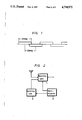
FIG. 2 is a block diagram broadly showing the principle of the present invention;
FIG. 3 (formed of FIGS. 3-I and 3-II) is a block diagram showing a satellite broadcasting receiver according to an embodiment of the present invention;
FIG. 4 is schematic representation showing a format of a satellite broadcast signal;
FIGS. 5A to 5D are diagrams showing the positions of carrier waves of FM audio signals for respective modes; and
FIG. 6, is a flow chart to which reference will be made in explaining the operation of the SHF receiver according to the invention in selecting the channels in sequence.
DESCRIPTION OF THE PREFERRED EMBODIMENT
Before describing a preferred embodiment of the present invention, the fundamental principle of the invention will be briefly described below with reference to FIG. 2.
In FIG. 2, a SHF receiver according to this invention is shown to comprise a receiving unit 1 for receiving satellite broadcast signals having different planes of polarization (for example, horizontal and vertical planes of polarization) for the adjacent channels, a switching unit 2 for changing-over the receiving plane of polarization of the receiving unit 1, and a controller, for example, a micro-computer 3, for controlling the operations of the receiving unit 1 and the switching unit 2. In response to the control by controller 3, receiving unit 1 sequentially selects every other channel, for example, the odd-numbered channels, whose satellite broadcast signals have a first polarization plane. Then, the switching unit 2 changes-over the receiving polarization plane from the first polarization plane to a second polarization plane and, thereafter, the receiving unit 1 sequentially selects the remaining alternate channels, for example, the even-numbered channels, whose satellite broadcast signals have the second plane of polarization.
As set forth above, after the alternate channels whose satellite broadcast signals having the first plane of polarization have been sequentially selected, the receiving plane of polarization is switched and then the other alternate channels whose satellite broadcast signals have the second plane of polarization are sequentially selected. Thus, although all the channels are eventually selected or scanned, the receiving plane of polarization is switched only once. Further, such switching of the receiving plane of polarization can be easily effected automatically.
Now, an embodiment of an SHF receive according to the present invention will be described in detail with reference to FIG. 3 (formed of FIGS. 3-I and 3-II on two sheets of drawings so as to be of sufficiently large scale).
In FIG. 3, a satellite broadcast signal SBS of the ku band (12 GHz band ranging from 11.7 to 12.2 GHz) or the c band (4 GHz band ranging from 3.7 to 4.2 GHz) is transmitted from a broadcasting satellite 10 and supplied through a BS antenna 11 to a polarizer 12a. This polarizer 12a may be of a well known type, for example, as is disclosed in U.S. Pat. No. 4,414,516. The satellite broadcast signal SBS received by polarizer 12a is supplied to a super-high frequency/ultra-high frequency (S/U) converter 12b. In S/U converter 12b, the satellite broadcast signal SBS is frequency-converted to a signal SBS, having a frequency of 950 to 1450 MHz with respect to both the ku band and the c band.
In other words, a local frequency suitably provided in the S/U converter 12b for frequency conversion is selectively provided with a frequency of 10.75 GHz for the ku band or with a frequency of 2.75 GHz for the c band. Although FIG. 3 shows a single system comprised of the BS antenna 11 and the S/U converter 12b, in practice, for the reception of the ku band and the c band, different respective systems, each formed of a BS antenna and an S/U converter, may be employed with a suitable arrangement being provided for selecting one system or the other and providing the respective local frequency.
As shown in FIG. 4, the satellite broadcast signal SBS is a signal in which a video signal Sv, whose highest frequency is 4.2 MHz, is frequency-multiplexed with an FM audio signal SAFM whose carrier wave is in a frequency band above the highest frequency of this video signal Sv, for example, in a 5 to 8.5 MHz band, and the carrier wave of 12 GHz or 4 GHz for the ku band or the c band, respectively, is frequency-modulated by the signals Sv and SAFM. Accordingly, the signal SBS, is also an FM signal.
The satellite broadcast signal SBS can have any one of 4 audio modes, such as, (1) a monaural mode; (2) a multiplex mode; (3) a discrete mode; and (4) a matrix mode.
The FM audio signal SAFM in the case of the monaural mode is a monaural audio signal SA which results from frequency-modulating a single carrier wave of 5 to 8.5 MHz. The frequency deviation thereof is suitably selected, for example, as 75 kHz. The FM audio signal SAFM in the case of the multiplex mode is a composed signal which results from mixing a sum signal (L+R) of a left audio signal L and a right audio signal R and a signal which results from frequency-modulating a single sub-carrier by a difference signal (L-R). In this case, the single carrier wave to be frequency modulated again has a frequency in the 5 to 8.5 MHz band, and its frequency deviation is suitably selected, for example, as 100 kHz.
The FM audio signal SAFM in the case of the discrete mode is formed by frequency-modulating first and second carrier waves of 5 to 8.5 MHz band by the left audio signal L and the right audio signal R, respectively. The frequency deviation of each carrier wave is suitably selected, for example, as 75 kHz. In this case, the spacing between the frequencies of the first and second carrier waves is selected, for example, as 0.18 MHz. Further, the FM audio signal SAFM in the case of the matrix mode results from frequency-modulating first and second carrier waves in the 5 to 8.5 MHz band by the sum signal (L+R) and the difference signal (L-R), respectively. The frequency deviation of each carrier wave is suitably selected, for example, as 100 kHz. In this case, the spacing between the first and second carrier waves is frequently selected to be 1.00 MHz.
The positions of the carrier waves in the FM audio signal SAFM are not standardized for the several modes, and thus they may be placed at any given positions in the range from 5.0 to 8.5 MHz. The positions at which the carrier waves are placed most frequently will be indicated below with reference to FIGS. 5A to 5D, respectively. In the case of th monaural mode and the multiplex mode (FIGS. 5A and 5B), the single carrier wave is positioned at 6.80 MHz; in the case of the discrete mode (FIG. 5C), the carrier waves are positioned at 5.58 MHz and 5.76 MHz; and, in the case of the matrix mode (FIG. 5D), the carrier waves are positioned at 5.80 MHz and 6.80 MHz.
By way of example, the number of channels available for the ku band and the c band is 24 channels. As earlier noted, the planes of polarization of the satellite broadcast signals for the respective channels are made different for the adjacent channels. For example, the odd-numbered channels, such as channels 1,3, . . . ,23 have horizontal planes of polarization, while the even-numbered channels, such as, channels 2,4, . . . ,24 have vertical planes of polarization, respectively. The foregoing ensures that although the necessary band width per channel is, for example, 27 MHz, and the frequency spacing between the adjacent channels is only about 20 MHz, as shown on FIG. 1, radio interference between the adjacent channels will be avoided.
Referring again to FIG. 3, it will be seen that the signal SBS' from S/U converter 12b is supplied through a terminal 13 to a signal processor 14 provided in a receiver 100. In signal processor 14, the signal SBS' having a frequency ranging from 950 to 1450 MHz is converted to an intermediate frequency signal having a frequency of, for example, 402.78 MHz, and then FM-demodulated and thereby delivered as a mixed signal SO which is formed of the video signal Sv and the FM audio signal SAFM shown in FIG. 4.
The received channel is selected by changing a local signal SL supplied to processor 14 from a PLL (phase locked loop) circuit 15 for frequency conversion of the signal SBS'. The PLL circuit 15 is controlled by a micro-computer 17 in response to the user's manipulation of an operation panel 16. More particularly, the frequency dividing ratio of a frequency divider (not shown) contained in the PLL circuit 15 may be controlled to determine the channel selected. A signal SAFT indicative of any change of the intermediate frequency is supplied from signal processor 14 to micro-computer 17 so that an AFT (automatic fine tuning) operation may be carried out for maintaining the intermediate frequency at 402.78 MHz.
The received channel may be selected at random by suitable actuation of a key-pad comprised of ten keys [1] to [0] provided on operation panel 16, or the channel selection may be effected in sequence by actuation of an up-key 161 or a down-key 162 on operation panel 16.
In order to effect random channel selection, the user inputs the numeral corresponding to the desired channel by suitably depressing one or more of the ten keys [1] to [0] on operational panel 16 and then depressing an enter key [ENTER]. As a result of the foregoing, the dividing ratio of the frequency divider contained in PLL circuit 15 is changed by micro-computer 17 so that the resulting changed frequency of the local signal SL from PLL circuit 15 is suitable for selecting or tuning to the desired channel.
As described above, the plane of polarization of the satellite broadcast signal SBS is either a horizontal or vertical plane of polarization in dependence on the channel. Accordingly, when the received channel is changed, the reception plane of polarization established by polarizer 12a must be matched with the new received channel. A key 163 on operation panel 16 is actuated to change-over the reception plane of polarization. More specifically, the state of a switching signal SPO supplied from micro-computer 17 through an amplifier 18 to a terminal 19 and used to control polarizer 12a to change-over the reception plane of polarization is alternated or changed by successive operations of key 163, thus changing-over the reception plane of polarization established by polarizer 12a.
In order to effect sequential channel selection, the user depresses up-key 161 or down-key 162 provided on operation panel 16. As a result of the foregoing, the dividing ratio of the frequency divider (not shown) contained in PLL circuit 15 is sequentially changed by micro-computer 17 so that the frequency of local signal SL from PLL circuit 15 is sequentially changed, and hence the received channel is changed in sequence so long as key 161 or 162 is depressed. When up-key 161 is depressed, the received channel is changed in the order of 1,3, . . . 23,2,4, 24,1,3, . . . On the other hand, when down-key 162 is depressed, the received channel is changed in the order of 23,21, . . . ,1,24,22, . . . ,2,23,21, . . . In other words, the received channel is selected from the odd channels in sequence and then from the even channels in sequence, alternately. Further, as described above, the plane of polarization for each odd channel is horizontal and the plane of polarization for each even channel is vertical so that when the selection is changed from among the even channels to among the odd channels, or from among the odd channels, to among the even channels, the reception plane of polarization is suitably changed. In other words, the state of switching signal SPO derived from micro-computer 17 is automatically changed for changing-over the reception plane of polarization only when the channel selection changes from among the odd- or even-numbered channels to among the even-or odd-numbered channels, respectively.
Referring now to the flow chart of FIG. 6 showing the program for the sequential channel selection operation, it will be seen that, in step A following the start of the program, it is determined or decided if either the up-key 161 or the down-key 162 is depressed. If the answer to decision step A is "NO", that step is iterated. If one of the keys 161 and 162 is depressed, the program goes to step 1 or step 9. If up-key 161 is depressed at step 1, "2" is added to the channel number CH at step 2. Then, the program goes to step 3 at which it is determined whether the channel number CH is at least equal to "25", that is, "25" or more. If the channel number CH is less than "25", the program immediately goes to step 4 at which the channel corresponding to the channel number CH is selected. However, when the channel number CH is equal to or more than "25", the program goes from step 3 to step 5. At step 5, it is determined whether the channel number CH is even or odd. If the channel number is odd, the program goes to step 6 at which the channel number "2" is selected. On the other hand, if the channel number is even, the program goes to step 7 at which the channel number CH "1" is selected. From step 6 or step 7, the program goes to step 8. At step 8, the reception plane of polarization is suitably switched and then the channel corresponding to the channel number CH is selected at step 4. From step 4, the program returns to step A which again decides if either of keys 161 and 162 is depressed. So long as the up-key 161 is depressed, the above mentioned operations are repeatedly executed. When the up-key 161 is released, the reception channel number existing at that time is ultimately selected.
When the down-key 162 is depressed at step 9, the program goes to step 10 at which "2" is subtracted from the channel number CH. Then, the program goes to step 11 at which it is decided whether the channel number CH is equal to or less than "0". If the channel number CH is not equal to or less than "0", the program goes to step 4. At step 4, the channel corresponding to the channel number CH is selected. On the other hand, if the channel number CH is equal to or less than "0", the program goes to step 12 at which it is decided whether the channel number CH is even or odd. If the channel number CH is odd, the channel number "24" is selected at step 13. On the other hand, if the channel number is even, the channel number "23" is selected at step 14. After step 13 or 14, the reception plane of polarization is switched at step 8 and the channel corresponding to the channel number CH is selected at step 4 and the program returns to step A. So long as the down-key 162 is depressed, the above mentioned operations are repeatedly executed. When the down-key 162 is released, the reception channel number existing at that time is ultimately selected.
In the course of the above described channel selection, a display section 201 of a display panel 20 (FIG. 3), displays the channel number of the received channel. In the state illustrated on FIG. 3, it will be seen that channel number "6" is selected. When the reception plane of polarization is switched to the horizontal or vertical plane or polarization, a display section 202 (H) or a display section 203 (V), respectively, is illuminated on display panel 20. A display section 204 on display panel 20 is illuminated when a satellite broadcast signal is received. A display section 205 on display panel 20 is illuminated when the received satellite broadcast signal is of a predetermined one of the bands, for example, the ku band or the c band.
The mixed signal SO (FIG. 4) derived from signal processor 14 is supplied to a de-emphasis circuit 21 in which the signal, which had undergone a pre-emphasis at the transmission side, is de-emphasized or re-converted to the original signal. The output signal from de-emphasis circuit 21 is supplied to a low pass filter 22 from which the video signal SV is derived. This video signal SV is amplified by an amplifier 23 and then supplied to an energy dispersal signal eliminating circuit 24. In circuit 24, an energy dispersal signal, which consists of a triangular wave superimposed upon the video signal SV at the transmission side, is removed from video signal SV, and signal SV from circuit 24 is delivered through a muting circuit 25 to an output terminal 26. The muting circuit 25 is controlled by a muting control signal SMV which is formed by signal processor 14 in response to the existence or non-existence of the carrier wave of the intermediate frequency of 402.78 MHz. When the carrier wave with the intermediate frequency of 402.78 is absent, muting circuit 25 is made operative, that is, placed in the muting state.
The mixed signal SO derived from signal processor 14 is also supplied to a band pass filter 30 from which there is derived the FM audio signal SAFM having a carrier wave in the 5.0 to 8.5 MHz band. This FM audio signal SAFM is supplied to PLL circuits 31 and 32, each of which includes a mixer and a frequency converter (not shown). These PLL circuits 31 and 32 are used to convert a carrier wave of the FM audio signal SAFM to a wave with the frequency of 10.7 MHz. In the example mentioned above, when the selected audio mode is the monaural mode or the multiplex mode, a single carrier wave in the 5.0 to 8.5 MHz band is used, and the converted output is derived from, for example, the PLL circuit 31. On the other hand, when the selected audio mode is the discrete mode or the matrix mode, first and second carrier waves in the 5.0 to 8.5 MHz band are used as described above, so that the converted outputs are derived from both the PLL circuits 31 and 32.
Since the frequencies of the carrier waves of the FM audio signal SAFM for the several modes are not determined uniformly or standardized, the carrier waves may be placed at any positions within 5.0 to 8.5 MHz band. Therefore, in order to receive a desired FM audio signal SAFM, that is, in order to convert the carrier wave of the FM audio signal SAFM to an intermediate frequency signal of 10.7 MHz, on the basis of the user's operation of keys on the operation panel 16, suitable frequency dividing ratio control signals SN1 and SN2 are supplied to PLL circuits 31 aand 32, respectively, from micro-computer 17 and the frequency dividing ratios of frequency dividers (not shown) contained in the PLL circuits 31 and 32 are correspondingly controlled so as to carry out the so-called tuning.
As earlier noted, the frequencies of the carrier waves of the FM audio signal SAFM for the several audio modes may be selected freely in a range from 5.0 to 8.5 MHz. As shown in FIGS. 5A to 5D, in the case of the monaural mode and the multiplex mode, the carrier waves are frequently given a frequency of 6.80 MHz; in the case of the discrete mode, the carriers are frequently given the frequencies of 5.58 MHz and 5.76 MHz; and, in the case of the matrix mode, the carriers are frequently given the frequencies 5.80 MHz and 6.80 MHz. A key 164 is provided on the operation panel 16 and may be depressed to select the audio mode. When this key 164 is depressed sequentially or repeatedly, the audio mode is changed in the sequential order of monaural mode, multiplex mode, discrete mode, matrix mode, monaural mode, . . . When the monaural mode or the multiplex mode is selected, tuning is automatically carried out so that they tuning frequency f1 in PLL circuit 31 becomes 6.80 MHz. When the audio mode is switched to the discrete mode, tuning is automatically carried out so that the tuning frequencies f1 and f2 of PLL circuits 31 and 32 become 5.58 MHz and 5.76 MHz, respectively. Further, when the audio mode is switched to the matrix mode, tuning is automatically carried out so that the tuning frequencies f1 and f2 of PLL circuits 31 and 32 become 5.80 MHz and 6.80 MHz, respectively. In each instance, the selected audio mode is displayed, for example, selection of the monaural, multiplex, discrete and matrix modes is indicated or displayed by selective illumination of display sections 206,207,208 and 209, respectively, on display panel 20.
Thus, upon changing-over from one to another of the audio modes, the tuning frequencies of the PLL circuits 31 and 32 are selected to have the predetermined values. However, if the carrier waves of the FM audio signal SAFM do not have these predetermined tuning frequencies, tuning can be nevertheless carried out by the user operating keys on the operation panel 16. For example, after an audio tuning key 165 on operation panel 16 is depressed, the ten keys [1] to [0] or the up-key 161 or the down-key 162 may be sued to select the tuning frequencies.
Referring to FIG. 3, it will be seen that an audio signal SA1 derived from PLL circuit 31 and having the carrier wave of 10.7 MHz is supplied through a band pass filter 33 with a narrow pass band and also through a band pass filter 34 with a wide pass band to fixed contacts A and B, respectively, of a change-over switch 35. Similarly, an audio signal SA2 having a carrier wave of 10.7 MHz and derived from the PLL circuit 32 is supplied through a band pass filter 36 with a narrow pass band and a band pass filter 37 with a wide pass band to fixed contacts A and B, respectively, of a change-over switch 38. When the audio mode is the monaural mode or the discrete mode, the frequency deviation is relatively narrow, for example, as small as 75 kHz, as described above. Thus, change-over switches 35 and 38 are then positioned as shown to engage the contacts A so that audio signals SA1 and SA2, after passage through narrow band pass filters 33 and 36, are derived from change-over switches 35 and 38. On the other hand, when the audio mode is the multiplex mode or the matrix mode, the frequency deviation is relatively wide, for example, as wide as 100 kHz, as described above, so that audio signals SA1 and SA2 passed through wide band pass filters 34 and 37 are derived from change-over switches 35 and 38. Two-bit control signals [A and B] are derived from micro-computer 17 in response to selection of the audio mode. More specifically, when the monaural mode is selected, there is generated a signal of [1,1]; when the multiplex mode is selected, there is generated a signal of [0,0]; when the discrete mode is selected, there is generated a signal of [1,0]; and when the matrix mode is selected, there is generated a signal [0,1].
As described above, the signal A is "1" for the monaural mode and the discrete mode, while it is "0" for the multiplex mode and the matrix mode. This signal A is supplied to change-over switches 35 and 38 as a control or switching signal therefor. When the signal A is "1", the change-over switches 35 and 38 are connected to their contacts A. When the signal A is "0", switches 35 and 38 are connected to their contacts B.
The audio signals derived from change-over switches 35 and 38 are supplied to FM demodulators 39 and 40, respectively. The demodulated outputs from these FM demodulators 39 and 40 are both supplied to an audio processor 41.
In audio processor 41, there are executed signal processing operations corresponding to the selected audio mode. For this purpose, the 2-bit signals A and B from micro-computer 17 are supplied to a decoder 42 for conversion in the latter to 4-bit signals a,b,c and d which are then supplied to audio processor 41 as control signals therefor. For example, in the case of the monaural mode, the 2-bit signal A,B of [1,1] is converted in decoder 42 to a 4-bit signal of [1,0,0,0]; in the case of the multiplex mode, the signal [0,0] is converted to a signal [0,1,0,0]; in the case of the discrete mode, the signal [1,0] is converted to a signal of [0,0,1,0]; and in the case of the matrix mode, the signal of [0,1] is converted to a signal of [0,0,0,1]. Thus, the audio processor 41 is controlled by these signals so as to carry out signal processing corresponding to each audio mode.
In the case of the monaural mode, monaural audio signals are derived from the first and second outputs of the audio processor 41 and delivered through amplifiers 43 and 44, muting circuits 45 and 46 to output terminals 47 and 48, respectively. In the case of the multiplex mode, the discrete mode or the matrix mode, left and right audio signals L and R are derived from the first and second outputs of the audio processor 41 and delivered through amplifiers 43 and 44 and muting circuits 45 and 46 to output terminals 47 and 48, respectively.
From the FM demodulators 39 and 40, there are derived signals SM1 and SM2 which become low level "0" in the presence of the audio signals SA1 and SA2 and high level "1" in the absence thereof. The signals SM1 and SM2 are supplied to an AND circuit 49. When the output of AND circuit 49 is at the high level "1", that is, when there exist neither audio signal SA1 nor audio signal SA2, muting circuits 45 and 46 are operated to mute the respective inputs.
It will be appreciated that the above described SHF receiver according to this invention for receiving satellite broadcast signals having different planes of polarization for adjacent or odd- and even-numbered channels, respectively, is operative, upon sequential channel selection, to sequentially select from among alternate or every other channel, for example, the odd-numbered channels, having a first plane of polarization, and then to automatically switch the receiving plane of polarization of a polarizer and sequentially select from among the other alternate channels, for example, the even-numbered channels, having a second plane of polarization. Thus, the occasions at which the reception planes of polarization need to be switched are considerably reduced for increasing the channel selection speed.
Further, according to the present invention, the reception planes of polarization can be switched automatically so that the user can be freed from the burdensome task of switching the reception plane of polarization.
Although the above described embodiment of the present invention involves an arrangement in which the plane of polarization for each odd-numbered channel is horizontal and the plane of polarization for each even-numbered channel is vertical, an arrangement opposite to the above can be employed, or the invention can be similarly applied when a clockwise circular polarization wave and a counter-clockwise circular polarization wave are employed for the odd- and even-numbered channels, respectively.
Further, although a single preferred embodiment of the invention has been described in detail, it will be apparent that the invention is not limited to that precise embodiment, and that many modifications and variations could be effected by one skilled in the art without departing from the spirit or scope of the invention as defined by the appended claims.

Claims (5)

What is claimed is:
1. An apparatus for receiving satellite broadcast signals broadcast in a number of channels occupying successively overlapping frequency bands with a first plane of polarization for first alternate channels and a second plane of polarization for second channels arranged between said first channels, said apparatus comprising:
antenna means for receiving said satellite broadcast signals;
polarizer means for receiving a satellite broadcast signal derived from said antenna means and providing a plane of polarization adapted to be switched for correspondence with the plane of polarization of the received satellite broadcast signal;
channel selecting means for sequentially selecting the channels of said satellite broadcast signals;
means for tuning to each channel selected by said channel selecting means; and
controlling means for automatically controlling the sequential selecting of the channels, the tuning of said tuning means and the switching of the plane of polarization of said polarizer means in accordance with a channel selected by said channel selecting means, said controlling means causing said channel selecting means to first select sequentially from among said first alternate channels having said first plane of polarization, and thereafter automatically switching the plane of polarization of said polarizer means and then causing channel selecting in sequence from among said second channels having said second plane of polarization.
2. An apparatus according to claim 1; in which said first channels are odd-numbered channels and said second channels are even-numbered channels.
3. An apparatus according to claim 2; in which said channel selecting means includes means for sequentially selecting said odd- and even-numbered channels in ascending order, and means for sequentially selecting said odd- and even-numbered channels in descending order.
4. An apparatus according to claim 1; in which said satellite broadcast signals are in a plurality of bands; and further comprising means for switching from one to another of said bands.
5. An apparatus according to claim 1; in which the satellite broadcast signals include audio information selectively provided in a plurality of different modes employing a single carrier wave and two carrier waves, respectively, which are modulated with different deviations; and further comprising means for selectively deriving audio information provided in a received satellite broadcast signal in any one of said modes.
US06/914,305 1985-10-21 1986-10-02 SHF receiver Expired - Lifetime US4710972A (en)

Applications Claiming Priority (2)

Application Number Priority Date Filing Date Title
JP60234976A JPH0666707B2 (en) 1985-10-21 1985-10-21 Receiving machine
JP60-234976 1985-10-21

Publications (1)

Publication Number Publication Date
US4710972A true US4710972A (en) 1987-12-01

Family

ID=16979196

Family Applications (1)

Application Number Title Priority Date Filing Date
US06/914,305 Expired - Lifetime US4710972A (en) 1985-10-21 1986-10-02 SHF receiver

Country Status (6)

Country Link
US (1) US4710972A (en)
EP (1) EP0220867B1 (en)
JP (1) JPH0666707B2 (en)
AU (1) AU589213B2 (en)
CA (1) CA1259662A (en)
DE (1) DE3650195T2 (en)

Cited By (27)

* Cited by examiner, † Cited by third party
Publication number Priority date Publication date Assignee Title
US4777657A (en) * 1987-04-01 1988-10-11 Iss Engineering, Inc. Computer controlled broadband receiver
WO1991007064A1 (en) * 1989-10-31 1991-05-16 At&E Corporation Scanning receiver with manual override of frequency scanning routine
US5073930A (en) * 1989-10-19 1991-12-17 Green James A Method and system for receiving and distributing satellite transmitted television signals
US5189413A (en) * 1985-11-27 1993-02-23 Seiko Corp. Scanning receiver with manual override of frequency scanning routine
US5416774A (en) * 1992-06-25 1995-05-16 Sony Corporation Digital broadcast receiver
US5970386A (en) * 1997-01-27 1999-10-19 Hughes Electronics Corporation Transmodulated broadcast delivery system for use in multiple dwelling units
US6122482A (en) * 1995-02-22 2000-09-19 Global Communications, Inc. Satellite broadcast receiving and distribution system
US6424817B1 (en) * 1998-02-04 2002-07-23 California Amplifier, Inc. Dual-polarity low-noise block downconverter systems and methods
US7142809B1 (en) 2001-02-27 2006-11-28 The Directv Group, Inc. Device and method to locally fill gaps in spotbeam satellite systems with frequency re-use
US7900230B2 (en) 2005-04-01 2011-03-01 The Directv Group, Inc. Intelligent two-way switching network
US7937732B2 (en) 2005-09-02 2011-05-03 The Directv Group, Inc. Network fraud prevention via registration and verification
US7945932B2 (en) 2005-04-01 2011-05-17 The Directv Group, Inc. Narrow bandwidth signal delivery system
US7950038B2 (en) 2005-04-01 2011-05-24 The Directv Group, Inc. Transponder tuning and mapping
US7954127B2 (en) 2002-09-25 2011-05-31 The Directv Group, Inc. Direct broadcast signal distribution methods
US7958531B2 (en) 2005-04-01 2011-06-07 The Directv Group, Inc. Automatic level control for incoming signals of different signal strengths
US7987486B2 (en) 2005-04-01 2011-07-26 The Directv Group, Inc. System architecture for control and signal distribution on coaxial cable
US7991348B2 (en) 2005-10-12 2011-08-02 The Directv Group, Inc. Triple band combining approach to satellite signal distribution
US8019275B2 (en) 2005-10-12 2011-09-13 The Directv Group, Inc. Band upconverter approach to KA/KU signal distribution
US8024759B2 (en) 2005-04-01 2011-09-20 The Directv Group, Inc. Backwards-compatible frequency translation module for satellite video delivery
US8229383B2 (en) 2009-01-06 2012-07-24 The Directv Group, Inc. Frequency drift estimation for low cost outdoor unit frequency conversions and system diagnostics
US8238813B1 (en) 2007-08-20 2012-08-07 The Directv Group, Inc. Computationally efficient design for broadcast satellite single wire and/or direct demod interface
US8549565B2 (en) 2005-04-01 2013-10-01 The Directv Group, Inc. Power balancing signal combiner
US8621525B2 (en) 2005-04-01 2013-12-31 The Directv Group, Inc. Signal injection via power supply
US8712318B2 (en) 2007-05-29 2014-04-29 The Directv Group, Inc. Integrated multi-sat LNB and frequency translation module
US8719875B2 (en) 2006-11-06 2014-05-06 The Directv Group, Inc. Satellite television IP bitstream generator receiving unit
US8789115B2 (en) 2005-09-02 2014-07-22 The Directv Group, Inc. Frequency translation module discovery and configuration
US9942618B2 (en) 2007-10-31 2018-04-10 The Directv Group, Inc. SMATV headend using IP transport stream input and method for operating the same

Families Citing this family (1)

* Cited by examiner, † Cited by third party
Publication number Priority date Publication date Assignee Title
JP2552030B2 (en) * 1990-09-27 1996-11-06 マスプロ電工株式会社 Satellite signal receiver

Citations (7)

* Cited by examiner, † Cited by third party
Publication number Priority date Publication date Assignee Title
US3931623A (en) * 1974-05-31 1976-01-06 Communications Satellite Corporation Reliable earth terminal for satellite communications
US4232397A (en) * 1977-08-26 1980-11-04 Hitachi, Ltd. Automatic channel selection apparatus
US4392247A (en) * 1980-05-29 1983-07-05 U.S. Philips Corporation Broadcast receiver with search tuning
US4509198A (en) * 1981-10-19 1985-04-02 Dx Antenna Company, Limited Satellite broadcast signal receiving system
US4527281A (en) * 1982-10-27 1985-07-02 Clarion Co., Ltd. Auto-scan changeover system for two-band radio receiver employing PLL frequency synthesizers
US4538175A (en) * 1980-07-11 1985-08-27 Microdyne Corporation Receive only earth satellite ground station
US4592093A (en) * 1984-01-13 1986-05-27 Sony Corporation Super high frequency receiver

Family Cites Families (3)

* Cited by examiner, † Cited by third party
Publication number Priority date Publication date Assignee Title
US4414516A (en) 1981-11-18 1983-11-08 Chaparral Communications, Inc. Polarized signal receiver system
DE3678861D1 (en) * 1985-03-25 1991-05-29 Toshiba Kawasaki Kk RECEIVING ARRANGEMENT FOR SATELLITE BROADCASTING.
US4723320A (en) * 1985-03-28 1988-02-02 Satellite Technology Services, Inc. Dual communication link for satellite TV receiver

Patent Citations (7)

* Cited by examiner, † Cited by third party
Publication number Priority date Publication date Assignee Title
US3931623A (en) * 1974-05-31 1976-01-06 Communications Satellite Corporation Reliable earth terminal for satellite communications
US4232397A (en) * 1977-08-26 1980-11-04 Hitachi, Ltd. Automatic channel selection apparatus
US4392247A (en) * 1980-05-29 1983-07-05 U.S. Philips Corporation Broadcast receiver with search tuning
US4538175A (en) * 1980-07-11 1985-08-27 Microdyne Corporation Receive only earth satellite ground station
US4509198A (en) * 1981-10-19 1985-04-02 Dx Antenna Company, Limited Satellite broadcast signal receiving system
US4527281A (en) * 1982-10-27 1985-07-02 Clarion Co., Ltd. Auto-scan changeover system for two-band radio receiver employing PLL frequency synthesizers
US4592093A (en) * 1984-01-13 1986-05-27 Sony Corporation Super high frequency receiver

Cited By (44)

* Cited by examiner, † Cited by third party
Publication number Priority date Publication date Assignee Title
US5189413A (en) * 1985-11-27 1993-02-23 Seiko Corp. Scanning receiver with manual override of frequency scanning routine
US4777657A (en) * 1987-04-01 1988-10-11 Iss Engineering, Inc. Computer controlled broadband receiver
US5073930A (en) * 1989-10-19 1991-12-17 Green James A Method and system for receiving and distributing satellite transmitted television signals
WO1991007064A1 (en) * 1989-10-31 1991-05-16 At&E Corporation Scanning receiver with manual override of frequency scanning routine
US5416774A (en) * 1992-06-25 1995-05-16 Sony Corporation Digital broadcast receiver
US20140162546A1 (en) * 1995-02-22 2014-06-12 Global Communications, Inc. Satellite broadcast receiving and distribution system
US20030040270A1 (en) * 1995-02-22 2003-02-27 Global Communications, Inc. Satellite broadcast receiving and distribution system
US6334045B1 (en) 1995-02-22 2001-12-25 Global Communications, Inc. Satellite broadcast receiving and distribution system
US6397038B1 (en) 1995-02-22 2002-05-28 Global Communications, Inc. Satellite broadcast receiving and distribution system
US20020094775A1 (en) * 1995-02-22 2002-07-18 Global Communications, Inc. Satellite broadcast receiving and distribution system
US7826791B2 (en) * 1995-02-22 2010-11-02 Global Communications, Inc. Satellite broadcast receiving and distribution system
US8666307B2 (en) * 1995-02-22 2014-03-04 Global Communications, Inc. Satellite broadcast receiving and distribution system
US6122482A (en) * 1995-02-22 2000-09-19 Global Communications, Inc. Satellite broadcast receiving and distribution system
US6917783B2 (en) 1995-02-22 2005-07-12 Global Communications, Inc. Satellite broadcast receiving and distribution system
US20050176365A1 (en) * 1995-02-22 2005-08-11 Global Communications, Inc. Satellite broadcast receiving and distribution system
US6947702B2 (en) 1995-02-22 2005-09-20 Global Communications, Inc. Satellite broadcast receiving and distribution system
US8583029B2 (en) 1995-02-22 2013-11-12 Global Communications, Inc. Satellite broadcast receiving and distribution system
US8165520B2 (en) 1995-02-22 2012-04-24 Global Communications, Inc. Satellite broadcast receiving and distribution system
US8095064B2 (en) 1995-02-22 2012-01-10 Global Communications, Inc. Satellite broadcast receiving and distribution system
US7542717B2 (en) 1995-02-22 2009-06-02 Global Communications, Inc. Satellite broadcast receiving and distribution system
US5970386A (en) * 1997-01-27 1999-10-19 Hughes Electronics Corporation Transmodulated broadcast delivery system for use in multiple dwelling units
US6493873B1 (en) 1997-01-27 2002-12-10 Hughes Electronics Corporation Transmodulator with dynamically selectable channels
US6424817B1 (en) * 1998-02-04 2002-07-23 California Amplifier, Inc. Dual-polarity low-noise block downconverter systems and methods
US7142809B1 (en) 2001-02-27 2006-11-28 The Directv Group, Inc. Device and method to locally fill gaps in spotbeam satellite systems with frequency re-use
US7308230B2 (en) 2001-02-27 2007-12-11 The Directv Group, Inc. Device and method to locally fill gaps in spotbeam satellite systems with frequency re-use
US20070037512A1 (en) * 2001-02-27 2007-02-15 Godwin John P Device and method to locally fill gaps in spotbeam satellite systems with frequency re-use
US7954127B2 (en) 2002-09-25 2011-05-31 The Directv Group, Inc. Direct broadcast signal distribution methods
US7950038B2 (en) 2005-04-01 2011-05-24 The Directv Group, Inc. Transponder tuning and mapping
US7958531B2 (en) 2005-04-01 2011-06-07 The Directv Group, Inc. Automatic level control for incoming signals of different signal strengths
US7987486B2 (en) 2005-04-01 2011-07-26 The Directv Group, Inc. System architecture for control and signal distribution on coaxial cable
US7945932B2 (en) 2005-04-01 2011-05-17 The Directv Group, Inc. Narrow bandwidth signal delivery system
US7900230B2 (en) 2005-04-01 2011-03-01 The Directv Group, Inc. Intelligent two-way switching network
US8024759B2 (en) 2005-04-01 2011-09-20 The Directv Group, Inc. Backwards-compatible frequency translation module for satellite video delivery
US8621525B2 (en) 2005-04-01 2013-12-31 The Directv Group, Inc. Signal injection via power supply
US8549565B2 (en) 2005-04-01 2013-10-01 The Directv Group, Inc. Power balancing signal combiner
US7937732B2 (en) 2005-09-02 2011-05-03 The Directv Group, Inc. Network fraud prevention via registration and verification
US8789115B2 (en) 2005-09-02 2014-07-22 The Directv Group, Inc. Frequency translation module discovery and configuration
US8019275B2 (en) 2005-10-12 2011-09-13 The Directv Group, Inc. Band upconverter approach to KA/KU signal distribution
US7991348B2 (en) 2005-10-12 2011-08-02 The Directv Group, Inc. Triple band combining approach to satellite signal distribution
US8719875B2 (en) 2006-11-06 2014-05-06 The Directv Group, Inc. Satellite television IP bitstream generator receiving unit
US8712318B2 (en) 2007-05-29 2014-04-29 The Directv Group, Inc. Integrated multi-sat LNB and frequency translation module
US8238813B1 (en) 2007-08-20 2012-08-07 The Directv Group, Inc. Computationally efficient design for broadcast satellite single wire and/or direct demod interface
US9942618B2 (en) 2007-10-31 2018-04-10 The Directv Group, Inc. SMATV headend using IP transport stream input and method for operating the same
US8229383B2 (en) 2009-01-06 2012-07-24 The Directv Group, Inc. Frequency drift estimation for low cost outdoor unit frequency conversions and system diagnostics

Also Published As

Publication number Publication date
DE3650195T2 (en) 1995-06-01
EP0220867A2 (en) 1987-05-06
DE3650195D1 (en) 1995-02-16
AU6325686A (en) 1987-04-30
JPS6295029A (en) 1987-05-01
EP0220867B1 (en) 1995-01-04
EP0220867A3 (en) 1989-04-26
CA1259662A (en) 1989-09-19
JPH0666707B2 (en) 1994-08-24
AU589213B2 (en) 1989-10-05

Similar Documents

Publication Publication Date Title
US4710972A (en) SHF receiver
CA1224529A (en) Shf receiver
KR0157413B1 (en) Receiver for terrestrial am and satellite fm-tv broadcasting signal
CA1066781A (en) Universal automotive electronic radio
US4352208A (en) Automatic IF selectivity for radio receiver system
US5014349A (en) Television tuner for common use in BS/UV
GB1562918A (en) Tuners for receiving broadcast signals
US4253194A (en) Receiver including a tuning circuit having a transmitter search
JPH06509691A (en) Adjacent channel controller for radio receivers
EP0451342B1 (en) Radio receiver with two receiving systems
US4584716A (en) Automatic dual diversity receiver
EP0668656B1 (en) A tuner for a satellite broadcasting receiver
US3801914A (en) Priority-frequency system for a signal-seeking receiver
GB2102229A (en) Television sound receivers
EP0437965A2 (en) Broadcast receiving apparatus for television signals
GB2238213A (en) Multiplex stereophonic demodulator for A2 and NICAM
JP3064390B2 (en) TV tuner
JPS631172A (en) Audio signal receiver
JPS58165485A (en) Radio frequency modulator
KR960000837Y1 (en) Sound signal detecting device of multi-tv type
JPH01112885A (en) Satellite broadcasting receiver
JPH04150406A (en) Satellite broadcast receiver
JPH02218226A (en) Channel selector for multi-receiver
JPH06101820B2 (en) Receiving machine
JPH06101826B2 (en) Receiving machine

Legal Events

Date Code Title Description
AS Assignment

Owner name: SONY CORPORATION, 7-35 KITASHINAGAWA-6, SHINAGAWA-

Free format text: ASSIGNMENT OF ASSIGNORS INTEREST.;ASSIGNORS:HAYASHI, TOSHIHIDE;YAMAKAMI, OSAMU;KANAYAMA, IKUO;REEL/FRAME:004613/0578

Effective date: 19860930

STCF Information on status: patent grant

Free format text: PATENTED CASE

FEPP Fee payment procedure

Free format text: PAYOR NUMBER ASSIGNED (ORIGINAL EVENT CODE: ASPN); ENTITY STATUS OF PATENT OWNER: LARGE ENTITY

FPAY Fee payment

Year of fee payment: 4

FPAY Fee payment

Year of fee payment: 8

FPAY Fee payment

Year of fee payment: 12