US4714122A - Weighing system for refuse trucks - Google Patents
Weighing system for refuse trucks Download PDFInfo
- Publication number
- US4714122A US4714122A US06/922,064 US92206486A US4714122A US 4714122 A US4714122 A US 4714122A US 92206486 A US92206486 A US 92206486A US 4714122 A US4714122 A US 4714122A
- Authority
- US
- United States
- Prior art keywords
- refuse
- truck
- container
- transducer
- switch
- Prior art date
- Legal status (The legal status is an assumption and is not a legal conclusion. Google has not performed a legal analysis and makes no representation as to the accuracy of the status listed.)
- Expired - Fee Related
Links
Images


Classifications
-
- B—PERFORMING OPERATIONS; TRANSPORTING
- B65—CONVEYING; PACKING; STORING; HANDLING THIN OR FILAMENTARY MATERIAL
- B65F—GATHERING OR REMOVAL OF DOMESTIC OR LIKE REFUSE
- B65F3/00—Vehicles particularly adapted for collecting refuse
- B65F3/02—Vehicles particularly adapted for collecting refuse with means for discharging refuse receptacles thereinto
- B65F3/04—Linkages, pivoted arms, or pivoted carriers for raising and subsequently tipping receptacles
- B65F3/041—Pivoted arms or pivoted carriers
- B65F3/043—Pivoted arms or pivoted carriers with additional means for keeping the receptacle substantially vertical during raising
-
- G—PHYSICS
- G01—MEASURING; TESTING
- G01G—WEIGHING
- G01G19/00—Weighing apparatus or methods adapted for special purposes not provided for in the preceding groups
- G01G19/08—Weighing apparatus or methods adapted for special purposes not provided for in the preceding groups for incorporation in vehicles
- G01G19/083—Weighing apparatus or methods adapted for special purposes not provided for in the preceding groups for incorporation in vehicles lift truck scale
-
- B—PERFORMING OPERATIONS; TRANSPORTING
- B65—CONVEYING; PACKING; STORING; HANDLING THIN OR FILAMENTARY MATERIAL
- B65F—GATHERING OR REMOVAL OF DOMESTIC OR LIKE REFUSE
- B65F3/00—Vehicles particularly adapted for collecting refuse
- B65F3/02—Vehicles particularly adapted for collecting refuse with means for discharging refuse receptacles thereinto
- B65F2003/022—Vehicles particularly adapted for collecting refuse with means for discharging refuse receptacles thereinto the discharging means comprising a device for determining the weight of the content of refuse receptacles
-
- B—PERFORMING OPERATIONS; TRANSPORTING
- B65—CONVEYING; PACKING; STORING; HANDLING THIN OR FILAMENTARY MATERIAL
- B65F—GATHERING OR REMOVAL OF DOMESTIC OR LIKE REFUSE
- B65F3/00—Vehicles particularly adapted for collecting refuse
- B65F3/02—Vehicles particularly adapted for collecting refuse with means for discharging refuse receptacles thereinto
- B65F2003/0263—Constructional features relating to discharging means
- B65F2003/0279—Constructional features relating to discharging means the discharging means mounted at the front of the vehicle
Definitions
- This invention relates generally to a weighing and recording system for refuse trucks.
- the invention is particularly directed to a weighing and recording system for refuse trucks of the type which pick up refuse or trash which is contained in large special refuse containers.
- refuse trucks and refuse containers There are several types of refuse trucks and refuse containers.
- the trucks and containers have complementary engaging elements which enable a truck to lift its complementary container from a lower resting position to an upper dumping position from which the contents of the container spill out of an opening in the container into an opening in the refuse receptacle of the truck.
- the refuse trucks are identified as "front end loaders”, “rear end loaders", and “side loaders”.
- Each refuse container is specifically adapted for a specific type of truck.
- Some trucks are also adapted with special lifting elements for handling smaller refuse containers, such as barrels or carts which are equipped with complementary lifting elements.
- the refuse trucks to which the present invention is directed are equipped with means for compacting the refuse so that the truck is capable of picking up refuse or trash from a large number of locations before the truck is completely full and ready for dumping at a specified dumping site.
- a fee is charged at the dumping site which is based on the poundage of the refuse which is dumped.
- the fee is determined by weighing the truck before and after dumping and charging for the difference in the two weights.
- the owner or contractor of the refuse truck can determine his or her cost of operating the truck to determine the fee to be charged to the customers.
- the dumping fee represents one cost factor for the total cost of operating the refuse truck.
- customers of the refuse pickup service pay a fixed fee for each refuse container of a particular type.
- This fee is arrived at by adding up all expenses and expected profits and dividing the total by the number of refuse containers serviced.
- the present system of setting charges for refuse pickup is objectionable to the contractor and to the customer for several reasons.
- Each truck has a particular route so that each refuse container is serviced on a specified day of the week and usually at a specified time of the day. Since each business and individual is unique there is great variation in the amount and nature of refuse in each container on the route. Some containers are nearly full at the time of pickup and some containers are nearly empty. Also, the type of refuse varies so that between two equally full containers, the refuse in one container may weight a great deal more than refuse in the other container. There is, of course, a cost involved in servicing all containers, whether they are full or empty.
- a principle object of the invention to provide a weighing system for a refuse truck which is capable of determing the weight of refuse in a refuse container as it is being serviced for the purpose of determining a per weight charge to the customer.
- Another object of this invention is the provision of a weighing system for refuse trucks for determining when the weight capacity of a truck has been reached.
- a further object of the present invention is the provision of weighing system for refuse trucks for determining the weight of refuse in each refuse container being serviced and for recording the weight for billing purposes.
- a still further object of the present invention is the provision of a weighing system for refuse trucks which automatically determines the weight of refuse in a refuse container as it is being serviced by the truck, requiring no attention on the driver's part except to note the identity of the customer being serviced.
- the invention consists of a weighing system for a refuse truck which is equipped with means for lifting a specific type of refuse container and dumping the contents of the refuse container into the truck.
- the weighing system comprises a transducer which is mounted on a refuse container lifting element of the truck for sensing the weight of the refuse container when it is full and when it is empty and for generating an electrical signal which is proportional to the weight which is sensed by the transducer.
- the weighing system also includes electrical digitizing means for converting the analog signal to a digital signal which is indicative of the weight which is sensed by the transducer, a source of electrical power, and a switch means, including a normally open switch which is operatively connected between the transducer and the source for electrical power, so that the switch is closed at a point during the lifting of a full refuse container and the lowering of an empty refuse container when the container is fully supported by the lifting means.
- the transducer is energized only when the switch is closed so that a signal is generated from the transducer at this point during the lifting and lowering the refuse container.
- FIG. 1 is a right-hand elevational view of a refuse truck which is equipped with a weighing system embodying the principles of the present invention
- FIG. 2 is a fragmentary side elevational view on an enlarged scale of one of the support arms of the truck with a transducer fixture applied thereto,
- FIG. 3 is a plan view of the support arm and transducer fixture of FIG. 2,
- FIG. 4 is a vertical cross-sectional view taken on the line IV--IV of FIG. 3 on a more enlarged scale
- FIG. 5 is a vertical cross-sectional view on a more enlarged scale, taken along line V--V of FIG. 4 and looking in the direction of the arrows,
- FIG. 6 is a vertical cross-sectional view on a still more enlarged scale, taken along line VI--VI of FIG. 4 and looking in the direction of the arrows,
- FIG. 7 is a vertical cross-sectional view taken along line VII--VII of FIG. 4 and looking in the direction of the arrows,
- FIG. 8 is a vertical cross-section view taken on along line VIII--VIII of FIG. 7 and looking in the direction of the arrows,
- FIG. 9 is a fragmentary side elevational view of part of the lifting mechanism of the truck and switch means for activating the transducer
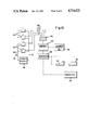
- FIG. 10 is an electrical schematic diagram of the weighing system
- FIG. 11 is a right side elevational view of a refuse truck of the rear end loader type, showing a first modified weighing system of the present invention
- FIG. 12 is a fragmentary right side elevational view of the rear portion of the truck on an enlarged scale showing the first modified weighing system applied to a refuse container of the type which is handled by a rear end loader,
- FIG. 13 is a fragmentary vertical cross-sectional view taken along line XIII--XIII of FIG. 12, showing the switch means for the first modified weighing system,
- FIG. 14 is a fragmentary right side elevational view of the rear portion of a refuse truck which is equipped with a specialized lifting system for small containers to which is applied a second modified weighing system embodying the principles of the present invention
- FIG. 15 is a view similar to FIG. 14 on an enlarged scale illustrating the specialized lifting apparatus and second modified weighing system applied to a small refuse container,
- FIG. 16 is a fragmentary side elevational view showing a limit switch which forms part of the second modified weighing system
- FIG. 17 is a view similar to FIG. 16, showing a limit switch in a different operating mode
- FIG. 18 is a vertical cross-sectional view of the limit switch of the second modified weighing system, showing the limit switch in a first open condition
- FIG. 19 is a view similar to FIG. 18, showing the limit switch of the second modification in a closed condition
- FIG. 20 is a view similar to FIG. 19, showing the limit switch of the second modified weighing system in a second open condition.
- FIG. 1 there is illustrated a first embodiment of a weighing system of the present invention which is generally indicated by the reference numeral 22.
- the weighing system 22 is shown in FIG. 1 applied to a front end loader refuse truck generally indicated by the reference numeral 24.
- the refuse truck 24 is adapted to handle a complementary refuse container, generally indicated by the reference numeral 26, which has an open top and an open ended sleeve 28 along each side of the container.
- the refuse truck 24 includes a pair of forwardly extending support arms 30 which are adapted to enter the sleeves 28 for engaging and lifting the container 26 in a manner to be described.
- Each support arm 30 is pivotally connected to an inverted U-shaped boom 32 by means of a pivot pin 34.
- the boom 32 is, in turn, pivotally connected to the side of the truck by a pivot pin 36.
- the support arm 30 is pivoted about the pin 34 by means of a first hydraulic actuator, generally indicated by the reference numeral 38.
- the boom 32 is pivoted about the pin 36 by means of a second hydraulic actuator, generally indicated by the reference numeral 40.
- the truck driver can control the operation of the first and second actuators independently throughout a dumping operation.
- the truck 24 When the container 26 is to be serviced, the truck 24 is driven toward the refuse container 26 so that the support arms are positioned in front of the container.
- the driver positions the support arms 30, so that they are generally horizontal and in horizontal alignment with the sleeves 28.
- the container 26 may be resting on the ground at the same level as the truck or it may be located at an elevated location.
- the support arms 30 are aligned with the sleeves 28, the truck is moved forwardly so that the support arms enter the sleeves 28.
- the boom 32 is then pivoted counterclockwise as viewed in FIG. 1 to raise the container 26 and bring it over the cab of the truck and above the refuse receptacle portion 41 of the truck.
- the driver of the truck also controls the operation of the first hydraulic actuator 38 to maintain the support arms 30 horizontal so that its open top of the refuse container remains horizontal to prevent spilling of the contents.
- the support arms 30 are pivoted counterclockwise as viewed in FIG. 1 so that the open top of the container 26 faces down toward the open top of the receptacle 41.
- the dumping position of the boom 32 and the support arms 30 is shown in dotted lines in FIG. 1.
- the weighing system 22 comprises a transducer, generally indicated by the reference numeral 42 and switch means generally indicated by the reference numeral 44.
- the transducer 42 includes a housing 46 on each support arm 30. As shown best in FIGS. 5 thru 7, the housing 46 is H-shaped in cross-section and is mounted on the support arm 30 so that the lower legs of the housing straddle the top of the support arm and are fixed to the support arm by means of welding or other fastening means.
- the upwardly extending legs of the housing form an elongated horizontal channel 48 which contains a pair of pressure load cells 50 and a plurality of stop means generally indicated by the reference numeral 52. Any number of load cells and stop means may be used.
- each load cell has an upwardly extending sensing element 56 which protrudes from the main body of the load cell.
- Each stop means 52 has a main body portion 58 and a plunger 64 which extends upwardly from the main body of the stop means.
- An elongated pressure plate 54 is also located in the channel 48 for vertical sliding movement within the channel and rests on the sensing elements 56 and the plungers 64.
- Each plunger 64 is slidably mounted vertically in a vertical hole 60 at the top of the main body 58. The plunger 64 is biased upwardly by means of a spring 62 at the bottom of the hole 60.
- the collective biasing force of all of the springs 62 is sufficient to support the pressure plate 54 so that it is positioned just above the sensing elements 56 and exerts little or no pressure on the sensing elements.
- the weight is detected by the sensors 56 and causes the pressure cells to generate an analog signal which is indicative of the weight sensed.
- Each sensor 56 is biased upwardly relative to the main body of the load cell and is forced into the main body of the load cell by downward pressure on the sensing element. The greater the weight or pressure on the sensing element, the greater the movement of the sensing element into the body of the load cell.
- the stop means 52 provide a safety feature against an unusually high application of force against the pressure plates 54 by limiting the downward movement of the pressure plates. If a downward pressure against the plates 54 exceeds the capacities of the load cells 50, the bottom of the pressure plates 54 will strike the tops of the bodies 58 of the stop means 52 before the critical point of each pressure load cell is reached. Such an unusually high pressure can be caused by many factors such as an upward jerking motion of the support arms 30 at the beginning of a lifting operation of the striking of an obstruction during a lifting operation.
- Each pressure plate 54 has a downwardly extending flange 66 at each end.
- Each flange 66 has a slot 68 which is spaced from the bottom of the flange.
- a screw 70 extends freely through the slot 68 and is threaded into the main body portion 58 of the adjacent stop means 52. The screws 70 restrain the plate 54 and maintain it within the channel 48 while allowing the pressure plate 54 to move vertically. There is sufficient clearance between the head of the screw 70 and the flange 66 to permit free vertical movement between the flange and the screw along the length of the slot 68.
- Switch means 44 comprises a normally open switch 72 which includes an upwardly extending plunger 74 which is biased outwardly or upwardly from the main portion of the switch.
- the switch 72 is closed when the plunger 74 is depressed within the main body of the switch.
- the end of the right hand boom 32 is provided with a cam surface 76 just below the pivot pin 36.
- the switch 72 is fixed to the truck at a point just below the cam surface 76 so that when the booms 32 are in the lower pickup position shown in full lines in FIG. 1 and the dumping position shown in dotted lines in FIG. 1, the cam surface 76 is out of contact with the plunger 74 of the switch.
- the cam surface 76 engages and depresses the plunger 74 to close the switch 72. Therefore, the switch 72 is closed when the booms are at the same point relative to the truck body whether the booms are being moved toward the dumping position or from the dumping position.
- the positioning of the switch 72 is such that it will be closed when the refuse container 26 is fully supported on the support arms 30 whether it is full or empty.
- the closing point of the switch is selected to be above the highest starting position of any refuse container 26 on the pickup route for the truck. This means that in every case the refuse container will be fully supported on the support arms 30 before the switch 72 is closed for every refuse container on the route.
- the load cells 50 are connected to a source of electrical power 78 by means of power lines 80 and 81.
- Normally open switch 72 is located on power line 80 so that the load cells 50 are normally not energized.
- the load cells 50 are connected to a junction box 82 of a load cell digitizer 84 by means of lines 83.
- an analog electrical signal is transmitted through the lines 83 to the load cells digitizer 84 for conversion into a digital signal which is proportional to the composite analog signals received by the digitizer.
- the digitizer 84 is provided with visual digital readout means which enable the truck operator to see each weight reading.
- the load cell digitizer 84 is also connected to a keyboard 86 for data input and selection of operational modes, such as net or gross weight, tare, track to 0 and printout
- the digitizer 84 is also connected to a printer 90, a card punching machine 92 and a computer 94 through an interface 88.
- a specific weight on the support arms 30 causes the pressure load cells 50 to generate a specific composite analog electrial signal.
- a specific analog signal will produce a specific digital readout in the load cell digitizer 84.
- the computer 94 can be programmed to control the readout of the load cell digitizer 84 so that it corresponds with actual weight on the load cells.
- the printer 90 produces a permanent record of the refuse ccntainer when it is empty and when it is full and the difference between the two weights which represents the actual weight of the refuse for billing purposes.
- the card punching machine also produces a card during these same figures which can be given to the customer as a receipt. The entire weighing operation is completely automatic. All that is required of the driver is to punch in a customer identification number on the keyboard 86. This information will also be recorded on the printer 90 and the card punching machine 92.
- the operator positions the support arms within the sleeves 28 and raises the booms 32 so that the container 26 is fully supported on the arms.
- the switch 72 is closed by the cam surface 76 which energizes the pressure cells 50.
- An electrical analog signal is generated from the cells 50 to the load cell digitizer 84 for recording the weight of the full container.
- the switch 72 opens to de-energize the cells 50 and the refuse from the container 26 is dumped into the receptacle 41 of the truck. The empty container 26 is then brought back toward the pickup position.
- the cam surface 76 again closes the switch 72 to energize the cells 50.
- the cells 50 then generate a composite electrical signal which is representative of the empty container and causes the load cell digitizer 84 to record a weight which represents the weight of the empty container.
- the computer 94 is programmed to cause the load cell digitizer to subtract the two weights to produce a readout of the difference between the two weights. This difference is recorded on the printer 90 and the card punching machine 92. The operator of the vehicle punches the customer identification number before or after a dumping operation so that the recorded weights are tied in with that particular customer.
- FIGS. 11 thru 13 there is illustrated a second embodiment of the invention which is generally indicated by the reference numeral 96 for application to a refuse truck, generally indicated by the reference numeral 98, of the type which is known as a rear end loader.
- the truck 98 has a refuse receptacle 99 which has a rear opening 100 and which is adapted to handle a particular type of refuse container which is generally indicated by the reference numeral 102.
- the refuse container 102 has a pair of upwardly and rearwardly extending brackets 104 at the upper rear corner of the container at the middle of the rear edge.
- a horizontal rod 106 is fixed to and extends between the brackets 104.
- a pin 108 extends from each side wall of the container 102 adjacent the upper forward corner of the container.
- This pin 108 is adapted to be supported in a cradle 110 which is fixed to the inside surface of the truck receptacle 99.
- the cradles 110 are raised and lowered by hydraulic drive means, not shown.
- the pins 108 are engaged by backing the truck toward the container 102 with the cradles 110 in a lower position so that they pass under the pins 108.
- a second operator who is standing at the rear of the vehicle causes the cradles 110 to be raised into engagement with the pins 108 by pressing an appropriate button on a control panel 111.
- the container lifting mechanism of the truck comprises a cable 112 which is operatively connected at one end to a winch mechanism, generally indicated by the reference numeral 114.
- the cable 112 extends over an idler sheave 116 and is connected at its opposite end to a hook 120 which is adapted to engage the horizontal rod 106.
- the dumping operation is controlled by the operator at the rear of the truck who pushes another button on the conrol panel 111 for actuating the winch mechanism 114.
- the winch mechanism 114 As the cable 112 is drawn linearally by the winch mechanism 114, the rear end of the container 102 is lifted and pivoted about the cradles 110 from the full line position to the dotted line position as shown in FIG. 12. This causes the refuse in the container 102 to spill out of the container through the top opening and into the rear opening 100 of the truck receptacle 99.
- the refuse container 15 is returned to its resting position when the operator at the rear of the vehicle presses another button to cause the winch mechanism 14 to release the cable 112 in a controlled manner.
- an additional amount of cable 112 is paid out to produce a slack which enables the operator to remove the hook 120 from the horizontal rod 106.
- the cradles 110 are then lowered by the operator to a point below the pins 108 to allow the truck to drive away from the, now empty, container 102.
- the second embodiment 96 of the invention comprises a tension load cell 118 which is located between the hook 120 and the cable 112 and switch means, generally indicated by the reference numeral 122.
- the switch means comprises a normally open switch 124 which is identical to switch 72 and includes a plunger 125 which operates in the same manner as the plunger 74 to open and close the switch.
- the switch 124 is fixed to the outside of the truck body and is located below a cam 126 which is mounted for rotation with a shaft 128 which is rotatably mounted on the truck body.
- a detector is also fixed to the shaft 128.
- the detector 130 includes a rearwardly extending portion 132 which is fixed to the shaft 128 and a laterally extending portion 134 which extends inwardly from the portion 132 so that it extends above the top edge of the container 102 as shown in FIG. 13.
- the shaft 128 is biased counterclockwise as viewed in FIG. 12 by a coil spring, not shown, so that the portion 132 rests against a stop 127.
- the control circuitry for the weighing system 96 of the second embodiment of the invention is identical to that of the first embodiment illustrated in FIG. 10, except that a single tension load cell is utilized instead of a plurality of pressure load cells for generating a single analog signal to the load cell digitizer.
- the switch 124 is identical to the switch 72 for energizing and de-energizing the load cell.
- a refuse pickup sequence is started by backing the truck 98 toward the refuse container 102, so that the cradles 110 are located just beneath the pins 108.
- the operator at the rear end of the truck presses a button on the panel 111 to raise the cradles 110 into engagement with the pins 108.
- the hook 120 is engaged with the rod 106 and another button on the control panel 111 is pushed to start the winch mechanism 114 which begins lifting the rear end of the refuse container 102 about the pivot pins 108.
- the top of the container engages the lateral portion 134 of the detector 130 and causes the shaft 128 to rotate clockwise as viewed in FIG. 12.
- Partial rotation of the shaft 128 brings a high point 129 of the cam 126 into engagement with the plunger 125 and depresses the plunger 125 sufficiently to close the switch 124.
- the tension load cells 118 is energized and generates an electrical analog signal to the load cell digitizer for recording the weight of the full refuse container 102.
- the winch mechanism 114 is actuated to lower the container back to its starting position.
- the switch 124 is again closed by the cam 126 for generating another signal to the load cell digitizer 84.
- the weight of the empty container is thereby recorded for determining the weight of the refuse which was dumped into the truck.
- FIGS. 14 thru 20 there is illustrated a third embodiment of the present invention, generally indicated by the reference numeral 140.
- the weighing system 140 is shown applied to a refuse truck 142 which is equipped with a specialized container lifting apparatus, generally indicated by the reference numeral 144, which is adapted for handling a special wheeled cart 146 which is illustrated in FIG. 15.
- the truck has a refuse receptacle 145 which has a rear opening 147.
- the front wall of the cart 146 is provided with a recess 148 and a pair of spaced horizontal rods which extend across the recess for the purpose of enabling the cart to be engaged and lifted by the lifting apparatus 144 of the truck.
- the spaced rods consist of an upper rod 150 and a lower rod 152.
- the hooks 154 and 156 are fixed to a flat plate 158 which is pivotally mounted on the truck 142 by means of a pivot pin 160.
- the hooks 154 and 156 are generally L-shaped.
- the hook 154 points upwardly and the hook 156 points downwardly.
- the cart 146 is emptied by wheeling the cart toward the rear of the truck and positioning the upper rod 150 on the hook 154.
- the operator at the rear end of the truck then presses an appropriate button on the control panel 161 which causes a lifting mechanism, not shown, to pivot the plate 158 clockwise as viewed in FIGS.
- the operator presses another button on the control panel 161 for lowering the cart, whereupon the weight of the cart shifts back to the hook 154.
- the cart 146 is then removed from the hook 154 and wheeled away from the truck.
- the weighing system 140 comprises a pressure load cell 163 which is mounted on the upper hook 154 and a normally open switch 162 which is fixed to the rear end of the truck in front of the plate 158.
- the pressure load cell 163 is positioned on the hook 154 so that when the cart 146 is mounted on the hook, the upper rod 150 rests on the sensing element of the pressure cell, as shown in FIG. 15.
- the switch 162 includes a plunger 164 which is normally biased outwardly toward the plate 158 but is normally depressed by the plate when the plate is in the rest position shown in FIG. 15.
- switch 162 The details of switch 162 are shown in FIGS. 18 thru 20.
- the main body of the switch 162 is made of an insulating material and includes a bore 165 within which the plunger 164 is slidably mounted.
- a spring 174 is located at the base of the bore for biasing the plunger 164 to its outermost position shown in FIG. 20.
- a pair of electrical contacts 166 extend from the bore 165 and are connected to power line 80 for energizing and de-energizing the pressure load cell 161.
- the circuitry for the weighing system 140 is identical to that shown in FIG. 10 except that the load cells 50 are replaced by the single pressure load cell 163 and the switch 72 is replaced by the switch 162.
- the plunger 164 comprises an outer insulated portion 168, an inner insulated portion 170 and an intermediate electrically conductive portion 172.
- the insulated portion 168 is aligned with the contacts 166 and 167, so that the switch 162 is effectively opened.
- the plunger 164 is partially extended as shown in FIG. 19 so that the conductive portion 172 is aligned with the contacts 166 and 167, a circuit is completed through line 80, so that the switch 162 is effectively closed.
- the plunger 164 is fully extended as shown in FIG. 20
- the insulated portion 170 is aligned with the contacts 166 and 167 so that the switch 162 is again effectively opened.
- the plunger 164 of the switch 162 is depressed by the plate 158 so that the switch 162 is closed and the pressure cell 161 is de-energized.
- the plate 158 is rotated about the pivot pin 160. This causes the container 156 to be lifted off the ground and to be fully supported by the lifting apparatus 144, as shown in FIG. 16.
- the plunger 164 is partially extended to the position shown in FIG. 19 so that the conductive portion 172 of the plunger is aligned with the contacts 166 and 167, thereby closing the switch 162.
- the plate 158 is thereby rotated counterclockwise by the lifting mechanism, not shown, so that the plate returns to the position shown in FIG. 16.
- the plunger 164 is partially depressed to the position shown in FIG. 19 so that the switch 162 is again closed, thereby energizing the pressure load cell 163.
- Another electrical analog signal is generated by the load cell 163 which is received by the load cell digitizer 84.
- this electrical signal differs from the first electrical signal and that it is indicative of the cart 146 minus its contents.
- the weight of the empty cart is thereby recorded for computing the weight of the refuse which has just been dumped into the truck.
Abstract
Description
Claims (10)
Priority Applications (11)
| Application Number | Priority Date | Filing Date | Title |
|---|---|---|---|
| US06/922,064 US4714122A (en) | 1986-10-20 | 1986-10-20 | Weighing system for refuse trucks |
| US07/050,321 US4771837A (en) | 1986-10-20 | 1987-05-14 | Weighing system |
| JP63500274A JPH02500778A (en) | 1986-10-20 | 1987-10-09 | Weighing system |
| BR8707839A BR8707839A (en) | 1986-10-20 | 1987-10-09 | WEIGHING SYSTEM FOR GARBAGE WAYS |
| AU83354/87A AU613887B2 (en) | 1986-10-20 | 1987-10-09 | Weighing system for refuse trucks |
| EP19870908031 EP0327593A4 (en) | 1986-10-20 | 1987-10-09 | Weighing system for refuse trucks. |
| HU876200A HUT52240A (en) | 1986-10-20 | 1987-10-09 | Weighing system for garbage trucks |
| PCT/US1987/002658 WO1988002849A1 (en) | 1986-10-20 | 1987-10-09 | Weighing system for refuse trucks |
| KR1019880700698A KR880701869A (en) | 1986-10-20 | 1988-06-20 | Weighing system |
| US07/220,794 US4854406A (en) | 1986-10-20 | 1988-07-18 | Weighing system |
| FI891869A FI891869A0 (en) | 1986-10-20 | 1989-04-19 | VAEGNINGSSYSTEM FOER AVFALLSFORDON. |
Applications Claiming Priority (1)
| Application Number | Priority Date | Filing Date | Title |
|---|---|---|---|
| US06/922,064 US4714122A (en) | 1986-10-20 | 1986-10-20 | Weighing system for refuse trucks |
Related Child Applications (1)
| Application Number | Title | Priority Date | Filing Date |
|---|---|---|---|
| US07/050,321 Continuation-In-Part US4771837A (en) | 1986-10-20 | 1987-05-14 | Weighing system |
Publications (1)
| Publication Number | Publication Date |
|---|---|
| US4714122A true US4714122A (en) | 1987-12-22 |
Family
ID=25446450
Family Applications (1)
| Application Number | Title | Priority Date | Filing Date |
|---|---|---|---|
| US06/922,064 Expired - Fee Related US4714122A (en) | 1986-10-20 | 1986-10-20 | Weighing system for refuse trucks |
Country Status (1)
| Country | Link |
|---|---|
| US (1) | US4714122A (en) |
Cited By (45)
| Publication number | Priority date | Publication date | Assignee | Title |
|---|---|---|---|---|
| NL8901884A (en) * | 1989-07-20 | 1991-02-18 | Leendert Leyendekker | Forklift truck with load measuring and recording system - uses pressure sensors mounted inside horizontal forks |
| US5004392A (en) * | 1984-02-20 | 1991-04-02 | Zoller-Kipper Gmbh | Device for emptying containers, especially refuse bins |
| US5038876A (en) * | 1990-03-05 | 1991-08-13 | Wray-Tech Instruments, Inc. | Hydraulic control system for weighing |
| US5064008A (en) * | 1990-03-05 | 1991-11-12 | Wray-Tech Instruments, Inc. | Hydraulic control system for weighing |
| US5065829A (en) * | 1990-03-05 | 1991-11-19 | Wray-Tech Instruments, Inc. | Hydraulic control system for weighing |
| US5065828A (en) * | 1990-03-05 | 1991-11-19 | Wray-Tech Instruments, Inc. | Hydraulic control system for weighing |
| US5083624A (en) * | 1990-02-13 | 1992-01-28 | Stress-Tek, Inc. | Deflection transducer for measuring vehicle loads and a system for mounting same |
| EP0483922A2 (en) * | 1990-10-30 | 1992-05-06 | Nv Nuyts Orb | Means of transport, such as garbage truck provided with means for lifting, tilting and weighting containers |
| US5119894A (en) * | 1991-02-19 | 1992-06-09 | Toter, Inc. | Weighing apparatus for weighing the contents of a refuse container and method |
| US5178226A (en) * | 1990-12-21 | 1993-01-12 | Allan Bowman | Load measuring system for refuse trucks |
| US5215155A (en) * | 1991-03-05 | 1993-06-01 | Mettler-Toledo A.G. | Weighing device for containers to be moved by an arm system |
| US5230393A (en) * | 1991-06-27 | 1993-07-27 | Mezey Armand G | Refuse collection and weighing system |
| US5245137A (en) * | 1990-12-21 | 1993-09-14 | Mobile Computing Corporation | Load measuring system for refuse trucks |
| US5252021A (en) * | 1989-11-03 | 1993-10-12 | Stein-Heurtey | Handling installation for iron and steel products |
| DE4231211C1 (en) * | 1992-09-18 | 1994-02-10 | Schenck Ag Carl | Device for emptying large containers |
| DE4419328C1 (en) * | 1994-06-02 | 1995-07-27 | Zoeller Kipper | Refuse collection vehicle attachment for emptying large containers |
| EP0695931A1 (en) | 1994-08-03 | 1996-02-07 | Eaton Corporation | Method/system for resetting the value of a control parameter indicative of gross combined weight of vehicles to a default value thereof |
| EP0695930A1 (en) | 1994-08-03 | 1996-02-07 | Eaton Corporation | Method/system for determination of gross combined weight of vehicles equipped with electronic data links |
| US5528499A (en) * | 1984-04-27 | 1996-06-18 | Hagenbuch; Leroy G. | Apparatus and method responsive to the on-board measuring of haulage parameters of a vehicle |
| EP0728681A1 (en) * | 1995-02-23 | 1996-08-28 | Max Aicher GmbH Entsorgungstechnik | Method and device for controlling a lifting device |
| US5631832A (en) * | 1984-04-27 | 1997-05-20 | Hagenbuch; Leroy G. | Apparatus and method responsive to the on-board measuring of haulage parameters of a vehicle |
| WO1997040352A1 (en) * | 1996-04-24 | 1997-10-30 | Hardy Instruments, Inc. | Refuse weighing system and method |
| US5703333A (en) * | 1996-01-23 | 1997-12-30 | Wray-Tech Instruments, Inc. | Surface mount torque loadcell |
| US5814771A (en) * | 1996-02-16 | 1998-09-29 | Structural Instrumentation, Inc. | On-board microprocessor controlled load weighing system |
| US5861580A (en) * | 1995-06-21 | 1999-01-19 | S' More, Inc. | Load cell and weighing system |
| US6422800B1 (en) * | 1998-09-14 | 2002-07-23 | Keith W. Reichow | On-board weighing system for front loading refuse vehicles |
| US6600111B2 (en) * | 2001-07-13 | 2003-07-29 | Gerald S. Simons | Portable weigh scale system for use with vehicles having lift truck forks or the like |
| US20030234122A1 (en) * | 2002-06-19 | 2003-12-25 | Kroll William P. | Fork tine scale technology |
| US20030235489A1 (en) * | 2002-06-24 | 2003-12-25 | Hoff William H. | Load control system for tandem pallet truck |
| US6730861B1 (en) * | 1999-11-04 | 2004-05-04 | Weigh Point Incorporated | Weigh sensed lift truck forks |
| US6732667B1 (en) * | 1997-03-14 | 2004-05-11 | Ken Von Muenster | Grain drill with weight sensing device for sensing the weight of seed grain in a hopper |
| US20050081652A1 (en) * | 2003-10-21 | 2005-04-21 | Jon Scott | Load Cell Having Improved Linearity and Temperature Transient Behavior |
| US20060193718A1 (en) * | 2005-02-28 | 2006-08-31 | Mecfor, Inc. | Container handling apparatus |
| US20100278620A1 (en) * | 2009-05-04 | 2010-11-04 | Rimsa James R | Refuse receptacle lifter mounting/weighing assembly |
| US20140069728A1 (en) * | 2011-02-11 | 2014-03-13 | Digi Sens Ag | Method and device for measuring the weight of a load to be hoisted onto a loading area |
| US20140236446A1 (en) * | 2011-10-10 | 2014-08-21 | Volvo Group North America, Llc | Refuse vehicle control system and method of controlling a refuse vehicle |
| CN104085636A (en) * | 2014-06-25 | 2014-10-08 | 长治清华机械厂 | Prepressing type garbage compactor having weighing function and weighing method thereof |
| US20160187188A1 (en) * | 2009-01-15 | 2016-06-30 | The Curotto-Can, Llc | Automated collection and scale system |
| US10072966B1 (en) * | 2017-10-23 | 2018-09-11 | Advanced Steel Recovery, Llc | System and method for fraud-free scrap removal and accounting |
| US10196204B2 (en) * | 2010-07-29 | 2019-02-05 | The Heil Co. | Scale based load limiting for refuse vehicles |
| CN109319356A (en) * | 2018-09-27 | 2019-02-12 | 重庆暄洁再生资源利用有限公司 | It is a kind of intelligence kitchen receive fortune and weighing device |
| CN110926578A (en) * | 2018-09-20 | 2020-03-27 | 卡哥特科专利许可有限公司 | Method and system for determining the weight of a removable platform |
| US10633180B2 (en) * | 2016-06-10 | 2020-04-28 | The Heil Co. | Refuse vehicle dump verification system and apparatus |
| CN111707344A (en) * | 2020-07-14 | 2020-09-25 | 上海思寒环保科技有限公司 | Vehicle-mounted weighing system |
| US11725977B2 (en) | 2009-02-19 | 2023-08-15 | The Heil Co. | Automated collection and scale system |
Citations (13)
| Publication number | Priority date | Publication date | Assignee | Title |
|---|---|---|---|---|
| US2757923A (en) * | 1952-12-05 | 1956-08-07 | John P Lefsheik | Fork lift tractor scale |
| US2851171A (en) * | 1955-07-25 | 1958-09-09 | Jourdan Concrete Pipe Co | Material handling apparatus |
| US3063576A (en) * | 1960-07-11 | 1962-11-13 | Chain Belt Co | Weighing means for fork-lift trucks |
| US3290931A (en) * | 1962-10-31 | 1966-12-13 | Girling Ltd | Weight sensing crane hook |
| US3321035A (en) * | 1965-07-23 | 1967-05-23 | Oswalt Ind Inc | Vehicle electronic scales mount |
| US3612490A (en) * | 1969-06-13 | 1971-10-12 | Machinery Co Const | Combination weighing and mixing apparatus for fertilizer or the like |
| US3659665A (en) * | 1970-07-27 | 1972-05-02 | Howe Richardson Scale Co | Electrical weighing systems with multiple incremental readouts |
| US3827514A (en) * | 1973-06-25 | 1974-08-06 | Weigh Tronix | Weight measuring hook block apparatus for cranes |
| US3910364A (en) * | 1975-01-20 | 1975-10-07 | Royal Industries | Trailer dumping and weighing system |
| US4281729A (en) * | 1979-08-23 | 1981-08-04 | Farley James E | Material weighing and bucket charging apparatus |
| US4393951A (en) * | 1980-12-09 | 1983-07-19 | Vibro-Meter S.A. | Measuring device of the useful load and of the load on the axles of a truck |
| US4420053A (en) * | 1981-08-20 | 1983-12-13 | Litco International Inc. | Fork lift weighing apparatus |
| US4645018A (en) * | 1984-12-28 | 1987-02-24 | Pontech Gesellschaft Fur Technologische Entwicklungen Mbh | Process and device for recording the weight of refuse material as the material is emptied into a refuse collecting vehicle |
-
1986
- 1986-10-20 US US06/922,064 patent/US4714122A/en not_active Expired - Fee Related
Patent Citations (13)
| Publication number | Priority date | Publication date | Assignee | Title |
|---|---|---|---|---|
| US2757923A (en) * | 1952-12-05 | 1956-08-07 | John P Lefsheik | Fork lift tractor scale |
| US2851171A (en) * | 1955-07-25 | 1958-09-09 | Jourdan Concrete Pipe Co | Material handling apparatus |
| US3063576A (en) * | 1960-07-11 | 1962-11-13 | Chain Belt Co | Weighing means for fork-lift trucks |
| US3290931A (en) * | 1962-10-31 | 1966-12-13 | Girling Ltd | Weight sensing crane hook |
| US3321035A (en) * | 1965-07-23 | 1967-05-23 | Oswalt Ind Inc | Vehicle electronic scales mount |
| US3612490A (en) * | 1969-06-13 | 1971-10-12 | Machinery Co Const | Combination weighing and mixing apparatus for fertilizer or the like |
| US3659665A (en) * | 1970-07-27 | 1972-05-02 | Howe Richardson Scale Co | Electrical weighing systems with multiple incremental readouts |
| US3827514A (en) * | 1973-06-25 | 1974-08-06 | Weigh Tronix | Weight measuring hook block apparatus for cranes |
| US3910364A (en) * | 1975-01-20 | 1975-10-07 | Royal Industries | Trailer dumping and weighing system |
| US4281729A (en) * | 1979-08-23 | 1981-08-04 | Farley James E | Material weighing and bucket charging apparatus |
| US4393951A (en) * | 1980-12-09 | 1983-07-19 | Vibro-Meter S.A. | Measuring device of the useful load and of the load on the axles of a truck |
| US4420053A (en) * | 1981-08-20 | 1983-12-13 | Litco International Inc. | Fork lift weighing apparatus |
| US4645018A (en) * | 1984-12-28 | 1987-02-24 | Pontech Gesellschaft Fur Technologische Entwicklungen Mbh | Process and device for recording the weight of refuse material as the material is emptied into a refuse collecting vehicle |
Cited By (78)
| Publication number | Priority date | Publication date | Assignee | Title |
|---|---|---|---|---|
| US5004392A (en) * | 1984-02-20 | 1991-04-02 | Zoller-Kipper Gmbh | Device for emptying containers, especially refuse bins |
| US5644489A (en) * | 1984-04-27 | 1997-07-01 | Hagenbuch; Leroy G. | Apparatus and method for identifying containers from which material is collected and loaded onto a haulage vehicle |
| US5995888A (en) * | 1984-04-27 | 1999-11-30 | Hagenbuch; Leroy G. | Apparatus and method responsive to the on-board measuring of haulage parameters of a vehicle |
| US5631832A (en) * | 1984-04-27 | 1997-05-20 | Hagenbuch; Leroy G. | Apparatus and method responsive to the on-board measuring of haulage parameters of a vehicle |
| US5631835A (en) * | 1984-04-27 | 1997-05-20 | Hagenbuch; Leroy G. | Apparatus for identifying containers from which refuse is collected and compiling a historical record of the containers |
| US5528499A (en) * | 1984-04-27 | 1996-06-18 | Hagenbuch; Leroy G. | Apparatus and method responsive to the on-board measuring of haulage parameters of a vehicle |
| US5650928A (en) * | 1984-04-27 | 1997-07-22 | Hagenbuch; Leroy G. | Apparatus and method responsive to the on-board measuring of haulage parameters of a vehicle |
| US5650930A (en) * | 1984-04-27 | 1997-07-22 | Hagenbuch; Leroy G. | Apparatus and method responsive to the on-board measuring of haulage parameters of a vehicle |
| US5742914A (en) * | 1984-04-27 | 1998-04-21 | Hagenbuch; Leroy G. | Apparatus and method responsive to the on-board measuring of haulage parameters of a vehicle |
| NL8901884A (en) * | 1989-07-20 | 1991-02-18 | Leendert Leyendekker | Forklift truck with load measuring and recording system - uses pressure sensors mounted inside horizontal forks |
| US5252021A (en) * | 1989-11-03 | 1993-10-12 | Stein-Heurtey | Handling installation for iron and steel products |
| US5083624A (en) * | 1990-02-13 | 1992-01-28 | Stress-Tek, Inc. | Deflection transducer for measuring vehicle loads and a system for mounting same |
| US5038876A (en) * | 1990-03-05 | 1991-08-13 | Wray-Tech Instruments, Inc. | Hydraulic control system for weighing |
| US5065828A (en) * | 1990-03-05 | 1991-11-19 | Wray-Tech Instruments, Inc. | Hydraulic control system for weighing |
| US5065829A (en) * | 1990-03-05 | 1991-11-19 | Wray-Tech Instruments, Inc. | Hydraulic control system for weighing |
| US5064008A (en) * | 1990-03-05 | 1991-11-12 | Wray-Tech Instruments, Inc. | Hydraulic control system for weighing |
| EP0483922A3 (en) * | 1990-10-30 | 1992-07-08 | Nv Nuyts Orb | Means of transport, such as garbage truck provided with means for lifting, tilting and weighting containers |
| US5344272A (en) * | 1990-10-30 | 1994-09-06 | Nv Nuyts Orb | Means of transport such as a garbage truck or such like, provided with a loading and tilting device for the handling of containers or such like |
| EP0483922A2 (en) * | 1990-10-30 | 1992-05-06 | Nv Nuyts Orb | Means of transport, such as garbage truck provided with means for lifting, tilting and weighting containers |
| US5245137A (en) * | 1990-12-21 | 1993-09-14 | Mobile Computing Corporation | Load measuring system for refuse trucks |
| US5178226A (en) * | 1990-12-21 | 1993-01-12 | Allan Bowman | Load measuring system for refuse trucks |
| US5119894A (en) * | 1991-02-19 | 1992-06-09 | Toter, Inc. | Weighing apparatus for weighing the contents of a refuse container and method |
| GB2253066A (en) * | 1991-02-19 | 1992-08-26 | Toter Inc | Weighing the contents of a container |
| US5215155A (en) * | 1991-03-05 | 1993-06-01 | Mettler-Toledo A.G. | Weighing device for containers to be moved by an arm system |
| US5230393A (en) * | 1991-06-27 | 1993-07-27 | Mezey Armand G | Refuse collection and weighing system |
| DE4231211C1 (en) * | 1992-09-18 | 1994-02-10 | Schenck Ag Carl | Device for emptying large containers |
| EP0588272A1 (en) * | 1992-09-18 | 1994-03-23 | Zöller-Kipper GmbH | Device for weighing and emptying large capacity containers |
| DE4419328C1 (en) * | 1994-06-02 | 1995-07-27 | Zoeller Kipper | Refuse collection vehicle attachment for emptying large containers |
| EP0685411A1 (en) | 1994-06-02 | 1995-12-06 | Zöller-Kipper GmbH | Apparatus for emptying large réceptacles |
| EP0695930A1 (en) | 1994-08-03 | 1996-02-07 | Eaton Corporation | Method/system for determination of gross combined weight of vehicles equipped with electronic data links |
| EP0695931A1 (en) | 1994-08-03 | 1996-02-07 | Eaton Corporation | Method/system for resetting the value of a control parameter indicative of gross combined weight of vehicles to a default value thereof |
| EP0728681A1 (en) * | 1995-02-23 | 1996-08-28 | Max Aicher GmbH Entsorgungstechnik | Method and device for controlling a lifting device |
| US5861580A (en) * | 1995-06-21 | 1999-01-19 | S' More, Inc. | Load cell and weighing system |
| US5703333A (en) * | 1996-01-23 | 1997-12-30 | Wray-Tech Instruments, Inc. | Surface mount torque loadcell |
| US5814771A (en) * | 1996-02-16 | 1998-09-29 | Structural Instrumentation, Inc. | On-board microprocessor controlled load weighing system |
| US5837945A (en) * | 1996-04-24 | 1998-11-17 | Hardy Instruments, Inc. | Refuse weighing system and method |
| AU712101B2 (en) * | 1996-04-24 | 1999-10-28 | Hardy Instruments, Inc. | Refuse weighing system and method |
| WO1997040352A1 (en) * | 1996-04-24 | 1997-10-30 | Hardy Instruments, Inc. | Refuse weighing system and method |
| US7765944B2 (en) | 1997-03-14 | 2010-08-03 | Digi-Star, Llc | Grain drill with accurate metering of the rate of planting of seed |
| US20070277714A1 (en) * | 1997-03-14 | 2007-12-06 | Wilson David E | Grain drill with accurate metering of the rate of planting of seed |
| US20090218147A1 (en) * | 1997-03-14 | 2009-09-03 | Wilson David E | Grain drill with accurate metering of the rate of planting of seed |
| US7523710B2 (en) | 1997-03-14 | 2009-04-28 | Ken VonMuenster | Grain drill with accurate metering of the rate of planting of seed |
| US7448335B2 (en) | 1997-03-14 | 2008-11-11 | Ken VonMuenster | Grain drill with accurate metering of the rate of planting of seed |
| US6732667B1 (en) * | 1997-03-14 | 2004-05-11 | Ken Von Muenster | Grain drill with weight sensing device for sensing the weight of seed grain in a hopper |
| US20040206281A1 (en) * | 1997-03-14 | 2004-10-21 | Wilson David E. | Grain drill with accurate metering of the rate of planting seed |
| US20080190338A1 (en) * | 1997-03-14 | 2008-08-14 | Ken Von Muenster | Grain drill with accurate metering of the rate of planting of seed |
| US7059258B2 (en) | 1997-03-14 | 2006-06-13 | Ken Von Muenster | Grain drill with accurate metering of the rate of planting seed |
| US7357087B2 (en) | 1997-03-14 | 2008-04-15 | Ken Von Muenster | Grain drill with accurate metering of the rate of planting of seed |
| US20060231001A1 (en) * | 1997-03-14 | 2006-10-19 | Wilson David E | Grain drill with accurate metering of the rate of planting of seed |
| US7273017B2 (en) | 1997-03-14 | 2007-09-25 | Ken Von Muenster | Grain drill with accurate metering of the rate of planting of seed |
| US6422800B1 (en) * | 1998-09-14 | 2002-07-23 | Keith W. Reichow | On-board weighing system for front loading refuse vehicles |
| US6730861B1 (en) * | 1999-11-04 | 2004-05-04 | Weigh Point Incorporated | Weigh sensed lift truck forks |
| US6600111B2 (en) * | 2001-07-13 | 2003-07-29 | Gerald S. Simons | Portable weigh scale system for use with vehicles having lift truck forks or the like |
| US20030234122A1 (en) * | 2002-06-19 | 2003-12-25 | Kroll William P. | Fork tine scale technology |
| US20030235489A1 (en) * | 2002-06-24 | 2003-12-25 | Hoff William H. | Load control system for tandem pallet truck |
| US20050081652A1 (en) * | 2003-10-21 | 2005-04-21 | Jon Scott | Load Cell Having Improved Linearity and Temperature Transient Behavior |
| US7407360B2 (en) * | 2005-02-28 | 2008-08-05 | Mecfor Inc. | Container handling apparatus |
| US20060193718A1 (en) * | 2005-02-28 | 2006-08-31 | Mecfor, Inc. | Container handling apparatus |
| US20160187188A1 (en) * | 2009-01-15 | 2016-06-30 | The Curotto-Can, Llc | Automated collection and scale system |
| US10982995B2 (en) | 2009-01-15 | 2021-04-20 | The Heil Co. | Vehicle collection bins and scale systems |
| US11725977B2 (en) | 2009-02-19 | 2023-08-15 | The Heil Co. | Automated collection and scale system |
| US20100278620A1 (en) * | 2009-05-04 | 2010-11-04 | Rimsa James R | Refuse receptacle lifter mounting/weighing assembly |
| US10766696B2 (en) | 2010-07-29 | 2020-09-08 | The Heil Co. | Scale based load limiting for refuse vehicles |
| US10196204B2 (en) * | 2010-07-29 | 2019-02-05 | The Heil Co. | Scale based load limiting for refuse vehicles |
| US9534948B2 (en) * | 2011-02-11 | 2017-01-03 | Digi Sens Ag | Method and device for measuring the weight of a load to be hoisted onto a loading area |
| US20140069728A1 (en) * | 2011-02-11 | 2014-03-13 | Digi Sens Ag | Method and device for measuring the weight of a load to be hoisted onto a loading area |
| US20140236446A1 (en) * | 2011-10-10 | 2014-08-21 | Volvo Group North America, Llc | Refuse vehicle control system and method of controlling a refuse vehicle |
| US10831201B2 (en) * | 2011-10-10 | 2020-11-10 | Volvo Truck Corporation | Refuse vehicle control system and method of controlling a refuse vehicle |
| CN104085636A (en) * | 2014-06-25 | 2014-10-08 | 长治清华机械厂 | Prepressing type garbage compactor having weighing function and weighing method thereof |
| US10633180B2 (en) * | 2016-06-10 | 2020-04-28 | The Heil Co. | Refuse vehicle dump verification system and apparatus |
| US11548730B2 (en) | 2016-06-10 | 2023-01-10 | The Heil Co. | Refuse vehicle dump verification system and apparatus |
| US10072966B1 (en) * | 2017-10-23 | 2018-09-11 | Advanced Steel Recovery, Llc | System and method for fraud-free scrap removal and accounting |
| CN110926578A (en) * | 2018-09-20 | 2020-03-27 | 卡哥特科专利许可有限公司 | Method and system for determining the weight of a removable platform |
| CN110926578B (en) * | 2018-09-20 | 2023-02-28 | 希尔博有限公司 | Method and system for determining the weight of a removable platform |
| CN109319356A (en) * | 2018-09-27 | 2019-02-12 | 重庆暄洁再生资源利用有限公司 | It is a kind of intelligence kitchen receive fortune and weighing device |
| CN109319356B (en) * | 2018-09-27 | 2024-02-13 | 重庆暄洁再生资源利用有限公司 | Intelligent kitchen collection, transportation and weighing device |
| CN111707344A (en) * | 2020-07-14 | 2020-09-25 | 上海思寒环保科技有限公司 | Vehicle-mounted weighing system |
| CN111707344B (en) * | 2020-07-14 | 2022-04-15 | 上海思寒环保科技有限公司 | Vehicle-mounted weighing system |
Similar Documents
| Publication | Publication Date | Title |
|---|---|---|
| US4714122A (en) | Weighing system for refuse trucks | |
| US4771837A (en) | Weighing system | |
| US4854406A (en) | Weighing system | |
| JP2886377B2 (en) | Measuring device and weighing method for waste collection vehicle | |
| US10982995B2 (en) | Vehicle collection bins and scale systems | |
| US20110116899A1 (en) | Refuse data collection system | |
| US4645018A (en) | Process and device for recording the weight of refuse material as the material is emptied into a refuse collecting vehicle | |
| US5304744A (en) | Method of collecting and recording refuse | |
| US11827467B2 (en) | Debris carts and systems and methods of using same | |
| WO2018191512A1 (en) | Debris carts and systems and methods of using same | |
| CA2964227A1 (en) | Debris carts and systems and methods of using same | |
| US5038876A (en) | Hydraulic control system for weighing | |
| US5065829A (en) | Hydraulic control system for weighing | |
| US11725977B2 (en) | Automated collection and scale system | |
| US5064008A (en) | Hydraulic control system for weighing | |
| CA1287842C (en) | Weighing system | |
| US5065828A (en) | Hydraulic control system for weighing | |
| WO2021064210A1 (en) | Refuse collection vehicle weighing system | |
| JP3171521B2 (en) | Waste collection device safety device | |
| WO1996017227A1 (en) | Method and apparatus for weighing garbage | |
| JP3102616B2 (en) | Weighing waste collection device | |
| FR2710884A1 (en) | Utility vehicle equipped with load-handling means | |
| JPH0921683A (en) | Apparatus for measuring and recording dust charging amount of dust collecting vehicle | |
| KR20000060835A (en) | Apparatus for truck lift scale |
Legal Events
| Date | Code | Title | Description |
|---|---|---|---|
| AS | Assignment |
Owner name: BREAKTHRU INDUSTRIES, INC., 203 CHURCH STREET, CLI Free format text: ASSIGNMENT OF ASSIGNORS INTEREST.;ASSIGNORS:APPLETON, GREGORY H.;MIKELK, PAUL D.;REEL/FRAME:004622/0212 Effective date: 19851020 |
|
| AS | Assignment |
Owner name: BLODGETT & BLODGETT, P.C., WORCESTER COUNTY, WORCE Free format text: SECURITY INTEREST;ASSIGNOR:BREAKTHRU INDUSTRIES, INC.;REEL/FRAME:004768/0805 Effective date: 19871008 |
|
| AS | Assignment |
Owner name: BLODGETT & BLODGETT, P.C., MASSACHUSETTS Free format text: ASSIGNMENT OF ASSIGNORS INTEREST.;ASSIGNOR:BREAKTHRU INDUSTRIES, INC.;REEL/FRAME:005175/0362 Effective date: 19890419 |
|
| FEPP | Fee payment procedure |
Free format text: PAT HLDR NO LONGER CLAIMS SMALL ENT STAT AS SMALL BUSINESS (ORIGINAL EVENT CODE: LSM2); ENTITY STATUS OF PATENT OWNER: LARGE ENTITY |
|
| AS | Assignment |
Owner name: WASTE MANAGEMENT, INC., ILLINOIS Free format text: ASSIGNMENT OF ASSIGNORS INTEREST.;ASSIGNOR:BLODGETT & BLODGETT;REEL/FRAME:005700/0884 Effective date: 19901112 |
|
| FPAY | Fee payment |
Year of fee payment: 4 |
|
| FEPP | Fee payment procedure |
Free format text: PAYOR NUMBER ASSIGNED (ORIGINAL EVENT CODE: ASPN); ENTITY STATUS OF PATENT OWNER: LARGE ENTITY |
|
| REMI | Maintenance fee reminder mailed | ||
| FP | Lapsed due to failure to pay maintenance fee |
Effective date: 19951227 |
|
| FEPP | Fee payment procedure |
Free format text: PETITION RELATED TO MAINTENANCE FEES FILED (ORIGINAL EVENT CODE: PMFP); ENTITY STATUS OF PATENT OWNER: LARGE ENTITY |
|
| FEPP | Fee payment procedure |
Free format text: PETITION RELATED TO MAINTENANCE FEES GRANTED (ORIGINAL EVENT CODE: PMFG); ENTITY STATUS OF PATENT OWNER: LARGE ENTITY |
|
| FPAY | Fee payment |
Year of fee payment: 8 |
|
| SULP | Surcharge for late payment | ||
| PRDP | Patent reinstated due to the acceptance of a late maintenance fee |
Effective date: 19970523 |
|
| REMI | Maintenance fee reminder mailed | ||
| LAPS | Lapse for failure to pay maintenance fees | ||
| FP | Lapsed due to failure to pay maintenance fee |
Effective date: 19991222 |
|
| LAPS | Lapse for failure to pay maintenance fees |
Free format text: PATENT EXPIRED FOR FAILURE TO PAY MAINTENANCE FEES (ORIGINAL EVENT CODE: EXP.) |
|
| STCH | Information on status: patent discontinuation |
Free format text: PATENT EXPIRED DUE TO NONPAYMENT OF MAINTENANCE FEES UNDER 37 CFR 1.362 |