US4719905A - Apparatus and method for maintaining vertebrae in a desired relationship - Google Patents
Apparatus and method for maintaining vertebrae in a desired relationship Download PDFInfo
- Publication number
- US4719905A US4719905A US06/936,314 US93631486A US4719905A US 4719905 A US4719905 A US 4719905A US 93631486 A US93631486 A US 93631486A US 4719905 A US4719905 A US 4719905A
- Authority
- US
- United States
- Prior art keywords
- rod
- clamp
- arcuate
- vertebra
- section
- Prior art date
- Legal status (The legal status is an assumption and is not a legal conclusion. Google has not performed a legal analysis and makes no representation as to the accuracy of the status listed.)
- Expired - Lifetime
Links
Images


Classifications
-
- A—HUMAN NECESSITIES
- A61—MEDICAL OR VETERINARY SCIENCE; HYGIENE
- A61B—DIAGNOSIS; SURGERY; IDENTIFICATION
- A61B17/00—Surgical instruments, devices or methods, e.g. tourniquets
- A61B17/56—Surgical instruments or methods for treatment of bones or joints; Devices specially adapted therefor
- A61B17/58—Surgical instruments or methods for treatment of bones or joints; Devices specially adapted therefor for osteosynthesis, e.g. bone plates, screws, setting implements or the like
- A61B17/68—Internal fixation devices, including fasteners and spinal fixators, even if a part thereof projects from the skin
- A61B17/70—Spinal positioners or stabilisers ; Bone stabilisers comprising fluid filler in an implant
- A61B17/7001—Screws or hooks combined with longitudinal elements which do not contact vertebrae
- A61B17/7002—Longitudinal elements, e.g. rods
- A61B17/7004—Longitudinal elements, e.g. rods with a cross-section which varies along its length
- A61B17/7005—Parts of the longitudinal elements, e.g. their ends, being specially adapted to fit in the screw or hook heads
-
- A—HUMAN NECESSITIES
- A61—MEDICAL OR VETERINARY SCIENCE; HYGIENE
- A61B—DIAGNOSIS; SURGERY; IDENTIFICATION
- A61B17/00—Surgical instruments, devices or methods, e.g. tourniquets
- A61B17/56—Surgical instruments or methods for treatment of bones or joints; Devices specially adapted therefor
- A61B17/58—Surgical instruments or methods for treatment of bones or joints; Devices specially adapted therefor for osteosynthesis, e.g. bone plates, screws, setting implements or the like
- A61B17/68—Internal fixation devices, including fasteners and spinal fixators, even if a part thereof projects from the skin
- A61B17/70—Spinal positioners or stabilisers ; Bone stabilisers comprising fluid filler in an implant
- A61B17/7001—Screws or hooks combined with longitudinal elements which do not contact vertebrae
- A61B17/7041—Screws or hooks combined with longitudinal elements which do not contact vertebrae with single longitudinal rod offset laterally from single row of screws or hooks
-
- A—HUMAN NECESSITIES
- A61—MEDICAL OR VETERINARY SCIENCE; HYGIENE
- A61B—DIAGNOSIS; SURGERY; IDENTIFICATION
- A61B17/00—Surgical instruments, devices or methods, e.g. tourniquets
- A61B17/56—Surgical instruments or methods for treatment of bones or joints; Devices specially adapted therefor
- A61B17/58—Surgical instruments or methods for treatment of bones or joints; Devices specially adapted therefor for osteosynthesis, e.g. bone plates, screws, setting implements or the like
- A61B17/68—Internal fixation devices, including fasteners and spinal fixators, even if a part thereof projects from the skin
- A61B17/70—Spinal positioners or stabilisers ; Bone stabilisers comprising fluid filler in an implant
- A61B17/7001—Screws or hooks combined with longitudinal elements which do not contact vertebrae
- A61B17/7002—Longitudinal elements, e.g. rods
- A61B17/701—Longitudinal elements with a non-circular, e.g. rectangular, cross-section
Definitions
- the present invention generally relates to the correction of spinal deformities. Specifically, the present invention provides an improved apparatus and method for maintaining vertebrae in a desired spatial relationship.
- Devices that include rigid plates are also known for the straightening of spinal deformities.
- the plates are relatively heavy and cannot be easily bent to have a curvature corresponding to the desired curvature of a particular spinal column.
- the rigid plates do not permit flexibility in locating the fasteners in the vertebrae.
- Another known device for correcting spinal deformities includes a straight ratchet rod.
- the rigid ratchet rod applies compressive force to the spinal column when attached to vertebrae by hooks connected to the rod.
- This device does not conform to curves in the spine and only functions to compress the spine.
- the corrective forces are generated by two steel rods which are wired around the spine.
- the rods may be bent to a desired curvature.
- the rods are not directly attached to all the vertebra that the rods span. Maintaining a desired spatial relationship between the vertebrae spanned by the rods is, at best, difficult.
- the device includes a plurality of plates. Each of the plates is secured over one end of a vertebra. Fasteners are connected to the vertebrae through the plates. A cable is then crimped in the head of the fastener to attach the cable to one vertebra. Tension is put on the cable while it is crimped to an adjacent vertebra until the desired correction is accomplished. This device can only put compressive forces on the spine so that the cables are always in tension. Once the cable is crimped in place, no further adjustment between the crimped fastener and cable is possible.
- the present invention provides an improved apparatus and method to maintain vertebrae in a desired relationship.
- force transmitting members are mounted in openings formed in the vertebrae.
- Base portions of clamps are connected with the fasteners.
- a rod is bent to the desired curvature of the spine.
- the bent rod is guided through each clamp.
- Nuts are then tightened on the force transmitting members against the clamps to grip the rod and hold it from axial and rotational movement relative to the vertebrae.
- FIG. 1 is a dorsal view of a portion of a spinal column with an apparatus constructed in accordance with the present invention installed to maintain a desired relationship of the vertebrae;
- FIG. 2 is a sagittal view of the spinal column in FIG. 1 illustrating how the apparatus of the present invention conforms to the curvature of the spine;
- FIG. 3 is an enlarged schematic illustration of a spinal column having a displaced vertebra
- FIG. 4 is an enlarged schematic illustration, similar to FIG. 3, illustrating how the vertebrae of FIG. 3 are held in a desired relationship by the apparatus of FIGS. 1 and 2;
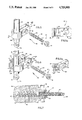
- FIG. 5 is a partially exploded fragmentary perspective view illustrating a clamp, rod and fastener of the apparatus of FIGS. 1 and 2;
- FIG. 5a is a partial cross sectional view, taken generally along the line 5a--5a of FIG. 5, illustrating the clamp with the rod removed;
- FIG. 6 is a partially exploded fragmentary perspective view illustrating a two-piece clamp, rod, and fastener of a second embodiment of the invention
- FIG. 6a is a perspective view, taken generally along the line 6a--6a of FIG. 6, illustrating one-half of the clamp with the rod removed;
- FIG. 7 is an enlarged fragmentary cross sectional view illustrating how the clamp and rod are connected with a vertebra by the fastener.
- FIG. 1 A pair of assemblies 20 for maintaining a desired relationship between adjacent vertebrae is illustrated in FIG. 1 installed on a human spinal column 26.
- Each of the assemblies 20 includes an elongated rod 30 connected with vertebra 34 by clamps generally designated 38 and fastener assemblies 42.
- the rod 30 is connected with the spinal column 26 to hold the vertebrae 34 in the desired spatial relationship with each other. This spatial relationship is shown in FIGS. 1 and 2. To enable the rod 30 to position vertebrae in the desired relationship with each other, the rod 30 must have a length sufficient to span at least three adjacent vertebrae 34. In the illustrated embodiment of the invention, the rod 30 spans six vertebrae 34.
- the rods 30 are bent to correspond to this curvature.
- the rods 30 have sufficient rigidity to maintain a configuration to which they are bent when the rods are resisting movement of one or more vertebrae back to deformed positions.
- the rods 30 were formed of surgical grade stainless steel and had a diameter of approximately 0.25 inches.
- the rods 30 Once the rods 30 have been plastically deformed or bent to the desired shape, they are inserted into clamps 38 which are held on the vertebrae by fastener assemblies 42.
- the fastener assemblies 42 are tightened, which presses the clamp 38 against the rod 30 to prevent the rod from rotational or axial movement.
- the position of the rod 30 can be adjusted, if so desired, by loosening the fastener assemblies 42. Once this has been done, the rods are moved to the desired position.
- the fastener assemblies are retightened to again firmly grip the rod.
- a vertebra 34a Prior to installing the assemblies 20, a vertebra 34a (FIG. 3) is out of place relative to adjacent vertebrae 34 which are in their normal positions.
- the assemblies 20 (FIG. 4) are installed to maintain the vertebrae 34 in a desired relationship in the spinal column 26.
- the spinous processes 46 (FIGS. 1-4) which project from the vertebrae 34 are to be removed. If it is determined that the spinous processes 46 will interfere with the installation of the assemblies 20, the spinous processes must be removed. If it is determined that the spinous processes 46 will not interfere with the installation of the assemblies 20, the spinous processes can be left on the vertebrae 34.
- the spinous processes 46 (FIG. 3) are illustrated as having been removed to allow the installation of the assemblies 20.
- a pair of holes 50 for receiving part of the fastener assemblies 42 are drilled in each vertebra 34 that will be spanned by rods 30.
- the holes 50 are drilled so that they will be in vertical alignment with holes drilled in the adjacent vertebra 34 when the vertebrae are in the desired relationship.
- Force transmitting members 52 (FIG. 7) are threaded into the holes 50.
- Clamps 38 (FIG. 4) for holding the rod 30 relative to the vertebra 34 are inserted over each force transmitting member 52.
- the clamps 38 are left loose on the force transmitting members 52.
- the rods 30 are bent to have a curvature corresponding to the desired curvature of the spinal column 26.
- the displaced vertebra 34a is held in the desired position relative to the adjacent vertebra while the bent rods 30 are inserted into the clamps 38.
- a tool (not shown) is placed on a flat portion 54 of the rod 30.
- the tool prevents the rod 30 from rotating as the clamps 38 are tightened around the rod.
- a nut 56 is threaded onto each of the force transmitting members 52 and tightened against the clamp to press the clamp to a vertebra 34. As the nut 56 is tightened, the clamp 38 also firmly grips the rod 30.
- the fastener assembly 42 (FIG. 7) connects a clamp 38 with a vertebra 34 and closes the clamp against a rod 30.
- the fastener assembly 42 includes a force transmitting member 52 (FIGS. 5 and 7) having a first threaded portion 62 and a second threaded portion 64.
- the first threaded portion 62 has a relatively large diameter helix for threading into a hole 50 in a vertebra 34.
- the first threaded portion 62 has a substantially larger crest diameter than the inside diameter of the hole 50.
- the helix cuts into the cylindrical side surface of the hole 50 to firmly attach force transmitting member 52 the vertebra 34.
- the force transmitting member 52 is threaded into the vertebra 34 by placing a tool (not shown) on the hex head portion 68. The tool and force transmitting member are then rotated until the desired depth of engagement with the vertebra 34 is obtained.
- the force transmitting member 52 is made from a surgical grade stainless steel or titanium.
- the second threaded portion 64 of the force transmitting member 52 has a standard external screw thread for engaging a standard internal thread in a nut 56.
- the nut 56 has a standard hexagonal external configuration for a suitable tool to engage and rotate the nut relative to the second threaded portion 64.
- the nut 56 is rotated until it abuttingly engages clamp 38. Rotation of the nut 56 is continued until the clamp 38 is pressed solidly against the vertebra 34 and the rod 30 is firmly clamped in place. After the nut 56 is rotated to its final desired position, the threaded portion 64 that extends beyond the nut 56 is trimmed off adjacent to the nut.
- the force transmitting member 52 has the same general construction disclosed in U.S. patent application Ser. No. 562,438, now U.S. Pat. No. 4,611,581, filed Dec. 16, 1983 for "Apparatus for Straightening Spinal Columns", by Arthur D. Steffee.
- the cylindrical rod 30 interconnects and holds a plurality of vertebrae in a desired spatial relationship. Before the rod 30 is installed in the clamps 38, the rod is bent to have a curvature corresponding to the desired curvature of the spinal column 26 (see FIG. 2). The bent rod 30 has sufficient rigidity to maintain its curvature and hold the vertebrae in place.
- the rod 30 has rounded ends 76.
- the rounded ends 76 allow the rod 30 to be easily inserted through the clamps 38 during installation.
- the rounded ends 76 also serve to prevent the rod 30 from damaging nearby tissue or bone that it may contact after installation.
- the rod 30 also has at least one portion with flats 54 in the rod.
- the flat portion 54 is gripped with a suitable tool to prevent the rod 30 from rotating about its axis when the clamps 38 are fastened around the rod to hold the rod in a desired position.
- the one-piece clamp 38 (FIG. 5) holds a rod 30 against rotational and axial movement relative to a vertebra.
- the one-piece clamp 38 has a base portion 84 and a clamp portion 86.
- the base portion 84 has two legs 88 extending from the clamp portion 86.
- the legs 88 are slightly spaced apart and the clamp portion 86 has a small resilient force acting to keep the legs spaced.
- Each of the legs 88 has a circular opening 90 for receiving the force transmitting member 52.
- the clamp portion 86 (FIG. 5a) has an arcuate wall inner surface 92 of a generally cylindrical configuration extending around most of the rod 30 for engaging and clamping a portion of the rod which is disposed in the clamp 38.
- the legs 88 extend from end portions of the inner surface 92.
- the inner surface 92 has an inner diameter slightly larger than the outer diameter of the rod 30.
- the legs 88 are resiliently pressed together by tightening nut 56 against the base portion 84.
- the tightening of nut 56 also reduces the inner diameter of the inner surface 92 slightly to firmly grip the rod 30 to hold the rod against axial and rotational movement.
- the clamp portion 86 has a pair of frustoconical surfaces 94 coaxially connected to inner surface 92 with their bases extending outward. The frustoconical surfaces 94 enable the rod 30 to be easily inserted in the clamp portions 86 during installation.
- the rod 30 is thereby maintained in the installed position due to the clamping force exerted around the rods by the inner surface 92 when the nut 56 is tightened to engage base portion 84. If any subsequent correction of the vertebrae is required, the clamps can be loosened to permit repositioning or replacement of the rod 30.
- a two-piece clamp 100 is illustrated in FIG. 6.
- the two-piece clamp 100 is made up of halves 102 and 104.
- Each half 102 or 104 has a base portion 106 and a clamp portion 108.
- the base portion 106 of each half 102 or 104 has an opening 110 for receiving the force transmitting member 52.
- the clamp portion 108 of half 102 has a semi-circular surface 112 and partial frustoconical surfaces 114.
- Frustoconical surfaces 114 are coaxial with arcuate surface 112, and have their bases extending outwardly.
- the clamp half 104 (FIG. 6a) has a web or tang 116 extending inwardly from the arcuate surface 112.
- the web 116 extends into a notch 122 (FIG. 6) in the rod 30.
- the web 116 and notch 122 cooperate to prevent axial and rotational movement of the rod 30 relative to the vertebrae 34 during and after installation.
- the arcuate surfaces 112 of halves 102, 104 form a generally cylindrical configuration when they are installed.
- the rod 30 has a plurality of the notches 122 spaced along the length of the rod.
- the distance between notches can be varied to accommodate different distances between vertebrae 34 as would be encountered with patients having different frame sizes.
- the installation of the two-piece clamp 100 and rod 30 with notches 122 is slightly different than the one-piece clamp 82.
- both halves 102, 104 of the two-piece clamp 100 are installed on the fasteners 42, the bent rod 30 is not threaded into the clamp.
- the halves 102, 104 merely are separated a sufficient distance to allow the rod 30 to be fitted laterally in between the halves.
- the nut 56 can be tightened against the clamp 100.
- the rod 30 has a flat portion 54 for maintaining an exact desired position of the rod during installation. Once the nuts 56 have been tightened, the tang 116 and the notch 122 cooperate to prevent any rotational or axial movement of the rod 30 relative to the vertebrae 34.
- the present invention provides an improved assembly 20 (FIG. 1) and method for maintaining vertebrae 34 in a desired relationship.
- the assembly 20 includes a rod 30, clamps generally designated 38, and fastener assemblies 42.
- Force transmitting members 52 are threaded into openings 50 in the vertebrae 34. Clamps 38 are put on the force transmitting members 52.
- a rod 30 is bent to a configuration which will maintain the vertebrae 34 in a desired relationship. The rod 30 is inserted into clamps 38. The rod 30 is held in place while nuts 56 are tightened to secure the clamps 38 to the vertebrae 34, and to press the clamps 38 against the rod 30.
Abstract
Description
Claims (13)
Priority Applications (1)
| Application Number | Priority Date | Filing Date | Title |
|---|---|---|---|
| US06936314 US4719905B1 (en) | 1985-11-01 | 1986-12-01 | Apparatus and method for maintaining vertebrae in a desired relationship |
Applications Claiming Priority (2)
| Application Number | Priority Date | Filing Date | Title |
|---|---|---|---|
| US06793901 US4648388B1 (en) | 1985-11-01 | 1985-11-01 | Apparatus and method for maintaining vertebrae in a desired relationship |
| US06936314 US4719905B1 (en) | 1985-11-01 | 1986-12-01 | Apparatus and method for maintaining vertebrae in a desired relationship |
Related Parent Applications (1)
| Application Number | Title | Priority Date | Filing Date |
|---|---|---|---|
| US06793901 Continuation US4648388B1 (en) | 1985-11-01 | 1985-11-01 | Apparatus and method for maintaining vertebrae in a desired relationship |
Publications (2)
| Publication Number | Publication Date |
|---|---|
| US4719905A true US4719905A (en) | 1988-01-19 |
| US4719905B1 US4719905B1 (en) | 1995-10-31 |
Family
ID=27121446
Family Applications (1)
| Application Number | Title | Priority Date | Filing Date |
|---|---|---|---|
| US06936314 Expired - Lifetime US4719905B1 (en) | 1985-11-01 | 1986-12-01 | Apparatus and method for maintaining vertebrae in a desired relationship |
Country Status (1)
| Country | Link |
|---|---|
| US (1) | US4719905B1 (en) |
Cited By (113)
| Publication number | Priority date | Publication date | Assignee | Title |
|---|---|---|---|---|
| WO1991016020A1 (en) * | 1990-04-26 | 1991-10-31 | Danninger Medical Technology, Inc. | Transpedicular screw system and method of use |
| US5074864A (en) * | 1988-12-21 | 1991-12-24 | Zimmer, Inc. | Clamp assembly for use in a spinal system |
| US5102412A (en) * | 1990-06-19 | 1992-04-07 | Chaim Rogozinski | System for instrumentation of the spine in the treatment of spinal deformities |
| US5112332A (en) * | 1988-12-21 | 1992-05-12 | Zimmer, Inc. | Method of performing spinal surgery |
| US5116334A (en) * | 1988-12-21 | 1992-05-26 | Zimmer, Inc. | Posterior spinal system and method |
| US5127912A (en) * | 1990-10-05 | 1992-07-07 | R. Charles Ray | Sacral implant system |
| US5133717A (en) * | 1990-02-08 | 1992-07-28 | Societe De Fabrication De Material Orthopedique Sofamor | Sacral support saddle for a spinal osteosynthesis device |
| US5147359A (en) * | 1988-12-21 | 1992-09-15 | Zimmer, Inc. | Spinal hook body |
| US5154718A (en) * | 1988-12-21 | 1992-10-13 | Zimmer, Inc. | Spinal coupler assembly |
| US5201734A (en) * | 1988-12-21 | 1993-04-13 | Zimmer, Inc. | Spinal locking sleeve assembly |
| US5209752A (en) * | 1991-12-04 | 1993-05-11 | Danek Medical, Inc. | Lateral offset connector for spinal implant system |
| US5217461A (en) * | 1992-02-20 | 1993-06-08 | Acromed Corporation | Apparatus for maintaining vertebrae in a desired spatial relationship |
| US5222954A (en) * | 1991-06-21 | 1993-06-29 | Artifex, Ltd. | Spinal implant system and method for installing the implant |
| WO1993014721A1 (en) * | 1992-01-28 | 1993-08-05 | Salut, Ltd. | Sacral implant system |
| US5282862A (en) * | 1991-12-03 | 1994-02-01 | Artifex Ltd. | Spinal implant system and a method for installing the implant onto a vertebral column |
| US5330472A (en) * | 1990-06-13 | 1994-07-19 | Howmedica Gmbh | Device for applying a tensional force between vertebrae of the human vertebral column |
| US5466237A (en) * | 1993-11-19 | 1995-11-14 | Cross Medical Products, Inc. | Variable locking stabilizer anchor seat and screw |
| US5487744A (en) * | 1993-04-08 | 1996-01-30 | Advanced Spine Fixation Systems, Inc. | Closed connector for spinal fixation systems |
| US5496321A (en) * | 1993-11-19 | 1996-03-05 | Cross Medical Products, Inc. | Rod anchor seat having a sliding interlocking rod connector |
| US5520687A (en) * | 1992-09-02 | 1996-05-28 | Advanced Spine Fixation Systems, Inc. | Low profile spine fixation system |
| US5571102A (en) * | 1992-09-15 | 1996-11-05 | Cavagna; Remi | System for spinal osteosynthesis |
| US5620443A (en) * | 1995-01-25 | 1997-04-15 | Danek Medical, Inc. | Anterior screw-rod connector |
| US5653708A (en) * | 1992-12-28 | 1997-08-05 | Advanced Spine Fixation Systems, Inc. | Cervical spine rod fixation system |
| US5662653A (en) * | 1996-02-22 | 1997-09-02 | Pioneer Laboratories, Inc. | Surgical rod-to-bone attachment |
| US5743907A (en) * | 1990-07-24 | 1998-04-28 | Acromed Corporation | Spinal column retaining method and apparatus |
| US6099528A (en) * | 1997-05-29 | 2000-08-08 | Sofamor S.N.C. | Vertebral rod for spinal osteosynthesis instrumentation and osteosynthesis instrumentation, including said rod |
| US6179838B1 (en) | 1998-02-24 | 2001-01-30 | Daniel Fiz | Bone fixation arrangements and method |
| JP2002204802A (en) * | 2001-01-10 | 2002-07-23 | Showa Ika Kohgyo Co Ltd | Osteosynthesis joining member |
| US6432108B1 (en) | 2000-01-24 | 2002-08-13 | Depuy Orthopaedics, Inc. | Transverse connector |
| US6458131B1 (en) | 2000-08-07 | 2002-10-01 | Salut, Ltd. | Apparatus and method for reducing spinal deformity |
| US6520990B1 (en) | 1990-10-05 | 2003-02-18 | Sdgi Holdings, Inc. | Lateral fixation plates for a spinal system |
| US20030065329A1 (en) * | 2001-10-03 | 2003-04-03 | Vaughan Paul A. | Vertebral stabilization assembly and method |
| US20030114853A1 (en) * | 2001-10-12 | 2003-06-19 | Ian Burgess | Polyaxial cross connector |
| US20030220642A1 (en) * | 2002-05-21 | 2003-11-27 | Stefan Freudiger | Elastic stabilization system for vertebral columns |
| US20040039385A1 (en) * | 2000-12-07 | 2004-02-26 | Keyvan Mazda | Device for fixing a rod and a spherical symmetry screw head |
| US20040049188A1 (en) * | 2002-09-09 | 2004-03-11 | Depuy Acromed, Inc. | Snap-on spinal rod connector |
| US20040092934A1 (en) * | 2002-04-24 | 2004-05-13 | Howland Robert S. | Multi selective axis spinal fixation system |
| US6736817B2 (en) | 1999-12-17 | 2004-05-18 | Thomas N. Troxell | Transconnector for coupling spinal rods |
| US20040111088A1 (en) * | 2002-12-06 | 2004-06-10 | Picetti George D. | Multi-rod bone attachment member |
| US6770075B2 (en) | 2001-05-17 | 2004-08-03 | Robert S. Howland | Spinal fixation apparatus with enhanced axial support and methods for use |
| US20040243128A1 (en) * | 2001-05-17 | 2004-12-02 | Howland Robert S. | Selective axis posterior lumbar spinal plating fixation apparatus and methods for use |
| US20050228377A1 (en) * | 2004-04-07 | 2005-10-13 | Depuy Spine, Inc. | Spinal cross-connectors |
| US20050228326A1 (en) * | 2004-03-31 | 2005-10-13 | Depuy Spine, Inc. | Head-to-head connector spinal fixation system |
| US20060058789A1 (en) * | 2004-08-27 | 2006-03-16 | Depuy Spine, Inc. | Dual rod cross connectors and inserter tools |
| USRE39035E1 (en) | 1994-11-18 | 2006-03-21 | Howmedica Osteonics Corp. | Universal coupler for spinal fixation |
| US20060064092A1 (en) * | 2001-05-17 | 2006-03-23 | Howland Robert S | Selective axis serrated rod low profile spinal fixation system |
| US20060064091A1 (en) * | 2004-03-31 | 2006-03-23 | Depuy Spine, Inc. | Rod attachment for head to head cross connector |
| US20060149231A1 (en) * | 2004-12-13 | 2006-07-06 | Rsb Spine Llc | Bone fastener assembly for bone retention apparatus |
| US20060167456A1 (en) * | 2004-12-21 | 2006-07-27 | Packaging Service Corporation Of Kentucky | Cervical plate system |
| US20060173454A1 (en) * | 2003-10-21 | 2006-08-03 | Innovative Spinal Technologies | Internal structure stabilization system for spanning three or more structures |
| US20060189999A1 (en) * | 2005-02-24 | 2006-08-24 | Paul Zwirkoski | Linked slideable and interlockable rotatable components |
| US20060271045A1 (en) * | 2005-05-27 | 2006-11-30 | Depuy Spine, Inc. | Spinal cross-connector |
| WO2007011779A2 (en) * | 2005-07-14 | 2007-01-25 | Medical Device Concepts, Llc | Dynamic spinal stabilization system |
| US20070043357A1 (en) * | 2005-07-29 | 2007-02-22 | X-Spine Systems, Inc. | Capless multiaxial screw and spinal fixation assembly and method |
| US20070049932A1 (en) * | 2005-08-23 | 2007-03-01 | Aesculap Ag & Co. Kg | Rod to rod connector |
| US20070055242A1 (en) * | 2005-07-27 | 2007-03-08 | Bailly Frank E | Device for securing spinal rods |
| US20070073289A1 (en) * | 2005-09-27 | 2007-03-29 | Depuy Spine, Inc. | Posterior dynamic stabilization systems and methods |
| US20080058808A1 (en) * | 2006-06-14 | 2008-03-06 | Spartek Medical, Inc. | Implant system and method to treat degenerative disorders of the spine |
| US20080065069A1 (en) * | 2006-09-07 | 2008-03-13 | Warsaw Orthopedic Inc. | Systems and methods for use in spinal support |
| US20080071277A1 (en) * | 2004-10-25 | 2008-03-20 | Warnick David R | Pedicle Screw Systems and Methods of Assembling/Installing the Same |
| US20080108989A1 (en) * | 2006-11-06 | 2008-05-08 | Douglas Eric Parsell | Device and method for less invasive surgical stabilization of pelvic fractures |
| US20080177315A1 (en) * | 2006-12-20 | 2008-07-24 | Aesculap Ii, Inc. | Rod to Rod Connector |
| US20080306556A1 (en) * | 2007-06-05 | 2008-12-11 | Spartek Medical, Inc. | Bone anchor with a curved mounting element for a dynamic stabilization and motion preservation spinal implantation system and method |
| US20080306528A1 (en) * | 2007-06-05 | 2008-12-11 | Spartek Medical, Inc. | Deflection rod system for spine implant with end connectors and method |
| US20080312655A1 (en) * | 2007-06-14 | 2008-12-18 | X-Spine Systems, Inc. | Polyaxial screw system and method having a hinged receiver |
| US20090105763A1 (en) * | 2007-10-17 | 2009-04-23 | X-Spine Systems, Inc. | Cross connector apparatus for spinal fixation rods |
| US7533933B2 (en) | 2004-08-12 | 2009-05-19 | Cybex Industrial, Ltd. | Child seat for a motor vehicle |
| US20090163961A1 (en) * | 2007-12-19 | 2009-06-25 | X-Spine Systems, Inc. | Offset multiaxial or polyaxial screw, system and assembly |
| US7588588B2 (en) | 2003-10-21 | 2009-09-15 | Innovative Spinal Technologies | System and method for stabilizing of internal structures |
| US7604655B2 (en) | 2004-10-25 | 2009-10-20 | X-Spine Systems, Inc. | Bone fixation system and method for using the same |
| US20100030267A1 (en) * | 2007-06-05 | 2010-02-04 | Spartek Medical, Inc. | Surgical tool and method for implantation of a dynamic bone anchor |
| US20100030273A1 (en) * | 2008-02-26 | 2010-02-04 | Spartek Medical, Inc. | Versatile polyaxial connector assembly and method for dynamic stabilization of the spine |
| US20100030274A1 (en) * | 2007-06-05 | 2010-02-04 | Spartek Medical, Inc. | Dynamic spinal rod and method for dynamic stabilization of the spine |
| US20100030270A1 (en) * | 2007-06-05 | 2010-02-04 | Spartek Medical, Inc. | Dynamic spinal rod assembly and method for dynamic stabilization of the spine |
| US20100030271A1 (en) * | 2008-02-26 | 2010-02-04 | Spartek Medical, Inc. | Modular in-line deflection rod and bone anchor system and method for dynamic stabilization of the spine |
| US20100030224A1 (en) * | 2008-02-26 | 2010-02-04 | Spartek Medical, Inc. | Surgical tool and method for connecting a dynamic bone anchor and dynamic vertical rod |
| US20100030279A1 (en) * | 2008-02-26 | 2010-02-04 | Spartek Medical, Inc. | Load-sharing bone anchor having a deflectable post and axial spring and method for dynamic stabilization of the spine |
| US20100036437A1 (en) * | 2008-02-26 | 2010-02-11 | Spartek Medical, Inc. | Load-sharing bone anchor having a deflectable post with a compliant ring and method for stabilization of the spine |
| US20100036435A1 (en) * | 2008-02-26 | 2010-02-11 | Spartek Medical, Inc. | Load-sharing bone anchor having a deflectable post and method for dynamic stabilization of the spine |
| US20100036436A1 (en) * | 2008-02-26 | 2010-02-11 | Spartek Medical, Inc. | Load-sharing bone anchor having a durable compliant member and method for dynamic stabilization of the spine |
| US7686835B2 (en) | 2005-10-04 | 2010-03-30 | X-Spine Systems, Inc. | Pedicle screw system with provisional locking aspects |
| US20100145389A1 (en) * | 2006-09-25 | 2010-06-10 | Stryker Spine | Rod inserter and rod with reduced diameter end |
| US20100168795A1 (en) * | 2008-02-26 | 2010-07-01 | Spartek Medical, Inc. | Load-sharing bone anchor having a natural center of rotation and method for dynamic stabilization of the spine |
| US20110118783A1 (en) * | 2009-11-16 | 2011-05-19 | Spartek Medical, Inc. | Load-sharing bone anchor having a flexible post and method for dynamic stabilization of the spine |
| US7963978B2 (en) | 2007-06-05 | 2011-06-21 | Spartek Medical, Inc. | Method for implanting a deflection rod system and customizing the deflection rod system for a particular patient need for dynamic stabilization and motion preservation spinal implantation system |
| US7967826B2 (en) | 2003-10-21 | 2011-06-28 | Theken Spine, Llc | Connector transfer tool for internal structure stabilization systems |
| US8021396B2 (en) | 2007-06-05 | 2011-09-20 | Spartek Medical, Inc. | Configurable dynamic spinal rod and method for dynamic stabilization of the spine |
| US8057515B2 (en) | 2008-02-26 | 2011-11-15 | Spartek Medical, Inc. | Load-sharing anchor having a deflectable post and centering spring and method for dynamic stabilization of the spine |
| US8097024B2 (en) | 2008-02-26 | 2012-01-17 | Spartek Medical, Inc. | Load-sharing bone anchor having a deflectable post and method for stabilization of the spine |
| US8097025B2 (en) | 2005-10-25 | 2012-01-17 | X-Spine Systems, Inc. | Pedicle screw system configured to receive a straight or curved rod |
| US8114134B2 (en) | 2007-06-05 | 2012-02-14 | Spartek Medical, Inc. | Spinal prosthesis having a three bar linkage for motion preservation and dynamic stabilization of the spine |
| US8197517B1 (en) | 2007-05-08 | 2012-06-12 | Theken Spine, Llc | Frictional polyaxial screw assembly |
| US8257397B2 (en) | 2009-12-02 | 2012-09-04 | Spartek Medical, Inc. | Low profile spinal prosthesis incorporating a bone anchor having a deflectable post and a compound spinal rod |
| US8337536B2 (en) | 2008-02-26 | 2012-12-25 | Spartek Medical, Inc. | Load-sharing bone anchor having a deflectable post with a compliant ring and method for stabilization of the spine |
| US8361117B2 (en) | 2006-11-08 | 2013-01-29 | Depuy Spine, Inc. | Spinal cross connectors |
| US8430916B1 (en) | 2012-02-07 | 2013-04-30 | Spartek Medical, Inc. | Spinal rod connectors, methods of use, and spinal prosthesis incorporating spinal rod connectors |
| US20130184759A1 (en) * | 2011-12-14 | 2013-07-18 | Spinicity, Inc. | Minimally Invasive Method And Apparatus For Stabilizing The Spinal Column |
| US8518085B2 (en) | 2010-06-10 | 2013-08-27 | Spartek Medical, Inc. | Adaptive spinal rod and methods for stabilization of the spine |
| US8771319B2 (en) | 2012-04-16 | 2014-07-08 | Aesculap Implant Systems, Llc | Rod to rod cross connector |
| US8821546B2 (en) | 2007-11-06 | 2014-09-02 | Stanus Investments, Inc. | Vertebral screw arrangement with locking pin |
| US8828056B2 (en) | 2012-04-16 | 2014-09-09 | Aesculap Implant Systems, Llc | Rod to rod cross connector |
| US9084634B1 (en) | 2010-07-09 | 2015-07-21 | Theken Spine, Llc | Uniplanar screw |
| US9241739B2 (en) | 2008-09-12 | 2016-01-26 | DePuy Synthes Products, Inc. | Spinal stabilizing and guiding fixation system |
| US9848918B2 (en) | 2005-11-21 | 2017-12-26 | DePuy Synthes Products, Inc. | Polyaxial bone anchors with increased angulation |
| US10105163B2 (en) | 2009-04-15 | 2018-10-23 | DePuy Synthes Products, Inc. | Revision connector for spinal constructs |
| US10136923B2 (en) | 2007-07-20 | 2018-11-27 | DePuy Synthes Products, Inc. | Polyaxial bone fixation element |
| US10154859B2 (en) | 2008-09-29 | 2018-12-18 | DePuy Synthes Products, Inc. | Polyaxial bottom-loading screw and rod assembly |
| US10405892B2 (en) | 2008-11-03 | 2019-09-10 | DePuy Synthes Products, Inc. | Uni-planer bone fixation assembly |
| US10507043B1 (en) | 2017-10-11 | 2019-12-17 | Seaspine Orthopedics Corporation | Collet for a polyaxial screw assembly |
| US10603083B1 (en) | 2010-07-09 | 2020-03-31 | Theken Spine, Llc | Apparatus and method for limiting a range of angular positions of a screw |
| US11006978B2 (en) | 2009-06-17 | 2021-05-18 | DePuy Synthes Products, Inc. | Revision connector for spinal constructs |
| US11083506B1 (en) * | 2020-02-10 | 2021-08-10 | DePuy Synthes Products, Inc. | Modular crimpable plate |
| US11510704B2 (en) * | 2005-04-27 | 2022-11-29 | Globus Medical, Inc. | Percutaneous vertebral stabilization system |
Citations (4)
| Publication number | Priority date | Publication date | Assignee | Title |
|---|---|---|---|---|
| GB2031508A (en) * | 1978-09-13 | 1980-04-23 | Gentile G | Screw clamp devices |
| DE3032237A1 (en) * | 1980-08-27 | 1982-03-04 | Fraunhofer-Gesellschaft zur Förderung der angewandten Forschung e.V., 8000 München | Bar implant for surgical scoliosis treatment - has hook secured to bar by friction and engaging vertebrae |
| US4483334A (en) * | 1983-04-11 | 1984-11-20 | Murray William M | External fixation device |
| US4611580A (en) * | 1983-11-23 | 1986-09-16 | Henry Ford Hospital | Intervertebral body stabilization |
-
1986
- 1986-12-01 US US06936314 patent/US4719905B1/en not_active Expired - Lifetime
Patent Citations (4)
| Publication number | Priority date | Publication date | Assignee | Title |
|---|---|---|---|---|
| GB2031508A (en) * | 1978-09-13 | 1980-04-23 | Gentile G | Screw clamp devices |
| DE3032237A1 (en) * | 1980-08-27 | 1982-03-04 | Fraunhofer-Gesellschaft zur Förderung der angewandten Forschung e.V., 8000 München | Bar implant for surgical scoliosis treatment - has hook secured to bar by friction and engaging vertebrae |
| US4483334A (en) * | 1983-04-11 | 1984-11-20 | Murray William M | External fixation device |
| US4611580A (en) * | 1983-11-23 | 1986-09-16 | Henry Ford Hospital | Intervertebral body stabilization |
Cited By (271)
| Publication number | Priority date | Publication date | Assignee | Title |
|---|---|---|---|---|
| US5074864A (en) * | 1988-12-21 | 1991-12-24 | Zimmer, Inc. | Clamp assembly for use in a spinal system |
| US5112332A (en) * | 1988-12-21 | 1992-05-12 | Zimmer, Inc. | Method of performing spinal surgery |
| US5116334A (en) * | 1988-12-21 | 1992-05-26 | Zimmer, Inc. | Posterior spinal system and method |
| US5147359A (en) * | 1988-12-21 | 1992-09-15 | Zimmer, Inc. | Spinal hook body |
| US5154718A (en) * | 1988-12-21 | 1992-10-13 | Zimmer, Inc. | Spinal coupler assembly |
| US5201734A (en) * | 1988-12-21 | 1993-04-13 | Zimmer, Inc. | Spinal locking sleeve assembly |
| US5133717A (en) * | 1990-02-08 | 1992-07-28 | Societe De Fabrication De Material Orthopedique Sofamor | Sacral support saddle for a spinal osteosynthesis device |
| US5474555A (en) * | 1990-04-26 | 1995-12-12 | Cross Medical Products | Spinal implant system |
| WO1991016020A1 (en) * | 1990-04-26 | 1991-10-31 | Danninger Medical Technology, Inc. | Transpedicular screw system and method of use |
| US5624442A (en) * | 1990-04-26 | 1997-04-29 | Cross Medical Products, Inc. | Transverse link for use with a spinal implant system |
| US5330472A (en) * | 1990-06-13 | 1994-07-19 | Howmedica Gmbh | Device for applying a tensional force between vertebrae of the human vertebral column |
| US5102412A (en) * | 1990-06-19 | 1992-04-07 | Chaim Rogozinski | System for instrumentation of the spine in the treatment of spinal deformities |
| US5743907A (en) * | 1990-07-24 | 1998-04-28 | Acromed Corporation | Spinal column retaining method and apparatus |
| US6080156A (en) * | 1990-07-24 | 2000-06-27 | Depuy Acromed, Inc. | Spinal column retaining method and apparatus |
| US6520990B1 (en) | 1990-10-05 | 2003-02-18 | Sdgi Holdings, Inc. | Lateral fixation plates for a spinal system |
| US5127912A (en) * | 1990-10-05 | 1992-07-07 | R. Charles Ray | Sacral implant system |
| US5300073A (en) * | 1990-10-05 | 1994-04-05 | Salut, Ltd. | Sacral implant system |
| US6197028B1 (en) * | 1990-10-05 | 2001-03-06 | Sdgi Holdings, Inc. | Sacral implant system |
| US5222954A (en) * | 1991-06-21 | 1993-06-29 | Artifex, Ltd. | Spinal implant system and method for installing the implant |
| US5282862A (en) * | 1991-12-03 | 1994-02-01 | Artifex Ltd. | Spinal implant system and a method for installing the implant onto a vertebral column |
| US5209752A (en) * | 1991-12-04 | 1993-05-11 | Danek Medical, Inc. | Lateral offset connector for spinal implant system |
| AU663918B2 (en) * | 1992-01-28 | 1995-10-26 | Salut, Ltd. | Sacral implant system |
| WO1993014721A1 (en) * | 1992-01-28 | 1993-08-05 | Salut, Ltd. | Sacral implant system |
| US5217461A (en) * | 1992-02-20 | 1993-06-08 | Acromed Corporation | Apparatus for maintaining vertebrae in a desired spatial relationship |
| US5776134A (en) * | 1992-09-02 | 1998-07-07 | Advanced Spine Fixation Systems, Inc. | Low-profile spinal fixation system |
| US5520687A (en) * | 1992-09-02 | 1996-05-28 | Advanced Spine Fixation Systems, Inc. | Low profile spine fixation system |
| US5571102A (en) * | 1992-09-15 | 1996-11-05 | Cavagna; Remi | System for spinal osteosynthesis |
| US5653708A (en) * | 1992-12-28 | 1997-08-05 | Advanced Spine Fixation Systems, Inc. | Cervical spine rod fixation system |
| US5487744A (en) * | 1993-04-08 | 1996-01-30 | Advanced Spine Fixation Systems, Inc. | Closed connector for spinal fixation systems |
| US5496321A (en) * | 1993-11-19 | 1996-03-05 | Cross Medical Products, Inc. | Rod anchor seat having a sliding interlocking rod connector |
| US5466237A (en) * | 1993-11-19 | 1995-11-14 | Cross Medical Products, Inc. | Variable locking stabilizer anchor seat and screw |
| USRE39035E1 (en) | 1994-11-18 | 2006-03-21 | Howmedica Osteonics Corp. | Universal coupler for spinal fixation |
| US6083224A (en) * | 1995-01-25 | 2000-07-04 | Sdgi Holdings, Inc. | Dynamic spinal screw-rod connectors |
| US6066140A (en) * | 1995-01-25 | 2000-05-23 | Sdgi Holdings, Inc. | Spinal rod transverse connectors |
| US6602254B2 (en) | 1995-01-25 | 2003-08-05 | Sdgi Holdings, Inc. | Spinal rod transverse connectors |
| US6471704B2 (en) | 1995-01-25 | 2002-10-29 | Sdgi Holdings, Inc. | Spinal rod transverse connectors |
| US5620443A (en) * | 1995-01-25 | 1997-04-15 | Danek Medical, Inc. | Anterior screw-rod connector |
| US6254603B1 (en) | 1995-01-25 | 2001-07-03 | Sdgi Holdings, Inc. | Spinal rod transverse connectors |
| US5662653A (en) * | 1996-02-22 | 1997-09-02 | Pioneer Laboratories, Inc. | Surgical rod-to-bone attachment |
| US6099528A (en) * | 1997-05-29 | 2000-08-08 | Sofamor S.N.C. | Vertebral rod for spinal osteosynthesis instrumentation and osteosynthesis instrumentation, including said rod |
| US6102912A (en) * | 1997-05-29 | 2000-08-15 | Sofamor S.N.C. | Vertebral rod of constant section for spinal osteosynthesis instrumentations |
| US6179838B1 (en) | 1998-02-24 | 2001-01-30 | Daniel Fiz | Bone fixation arrangements and method |
| US6736817B2 (en) | 1999-12-17 | 2004-05-18 | Thomas N. Troxell | Transconnector for coupling spinal rods |
| US6761721B2 (en) | 2000-01-24 | 2004-07-13 | Depuy Acromed, Inc. | Transverse connector |
| US6432108B1 (en) | 2000-01-24 | 2002-08-13 | Depuy Orthopaedics, Inc. | Transverse connector |
| US6458131B1 (en) | 2000-08-07 | 2002-10-01 | Salut, Ltd. | Apparatus and method for reducing spinal deformity |
| US20040039385A1 (en) * | 2000-12-07 | 2004-02-26 | Keyvan Mazda | Device for fixing a rod and a spherical symmetry screw head |
| US7166108B2 (en) * | 2000-12-07 | 2007-01-23 | Abbott Spine | Device for fixing a rod and a spherical symmetry screw head |
| JP2002204802A (en) * | 2001-01-10 | 2002-07-23 | Showa Ika Kohgyo Co Ltd | Osteosynthesis joining member |
| US6770075B2 (en) | 2001-05-17 | 2004-08-03 | Robert S. Howland | Spinal fixation apparatus with enhanced axial support and methods for use |
| US20060064092A1 (en) * | 2001-05-17 | 2006-03-23 | Howland Robert S | Selective axis serrated rod low profile spinal fixation system |
| US20050216005A1 (en) * | 2001-05-17 | 2005-09-29 | Howland Robert S | Selective axis anchor screw posterior lumbar plating system |
| US20040243128A1 (en) * | 2001-05-17 | 2004-12-02 | Howland Robert S. | Selective axis posterior lumbar spinal plating fixation apparatus and methods for use |
| US20030065329A1 (en) * | 2001-10-03 | 2003-04-03 | Vaughan Paul A. | Vertebral stabilization assembly and method |
| US20040193161A1 (en) * | 2001-10-03 | 2004-09-30 | Vaughan Paul A. | Vertebral stabilization assembly and method |
| US7645280B2 (en) | 2001-10-03 | 2010-01-12 | Vaughan Medical Technologies, Inc. | Vertebral stabilization assembly and method |
| US20040254578A1 (en) * | 2001-10-03 | 2004-12-16 | Vaughan Paul A. | Vertebral stabilization assembly and method |
| US7713291B2 (en) | 2001-10-03 | 2010-05-11 | Vaughan Medical Technologies, Inc. | Vertebral stabilization assembly and method |
| US7087056B2 (en) | 2001-10-03 | 2006-08-08 | Vaughan Medical Technologies, Inc. | Vertebral stabilization assembly and method |
| US20050240183A1 (en) * | 2001-10-03 | 2005-10-27 | Vaughan Medical Technologies, Inc. | Vertebral stabilization assembly and method |
| US20050267473A1 (en) * | 2001-10-03 | 2005-12-01 | Vaughan Paul A | Vertebral stabilization assembly and method with rigid and semi-rigid members |
| US20060149243A1 (en) * | 2001-10-03 | 2006-07-06 | Vaughan Paul A | Vertebral stabilization assembly and method |
| US7713290B2 (en) | 2001-10-03 | 2010-05-11 | Vaughan Medical Technologies, Inc. | Vertebral stabilization assembly and method |
| US20030114853A1 (en) * | 2001-10-12 | 2003-06-19 | Ian Burgess | Polyaxial cross connector |
| US20040092934A1 (en) * | 2002-04-24 | 2004-05-13 | Howland Robert S. | Multi selective axis spinal fixation system |
| US7314467B2 (en) | 2002-04-24 | 2008-01-01 | Medical Device Advisory Development Group, Llc. | Multi selective axis spinal fixation system |
| US8414618B2 (en) | 2002-05-21 | 2013-04-09 | Spinelab Ag | Elastic stabilization system for vertebral columns |
| US20030220642A1 (en) * | 2002-05-21 | 2003-11-27 | Stefan Freudiger | Elastic stabilization system for vertebral columns |
| US7125410B2 (en) * | 2002-05-21 | 2006-10-24 | Spinelab Gmbh | Elastic stabilization system for vertebral columns |
| US7066938B2 (en) | 2002-09-09 | 2006-06-27 | Depuy Spine, Inc. | Snap-on spinal rod connector |
| US20040049188A1 (en) * | 2002-09-09 | 2004-03-11 | Depuy Acromed, Inc. | Snap-on spinal rod connector |
| US20040111088A1 (en) * | 2002-12-06 | 2004-06-10 | Picetti George D. | Multi-rod bone attachment member |
| US7588588B2 (en) | 2003-10-21 | 2009-09-15 | Innovative Spinal Technologies | System and method for stabilizing of internal structures |
| US20060173454A1 (en) * | 2003-10-21 | 2006-08-03 | Innovative Spinal Technologies | Internal structure stabilization system for spanning three or more structures |
| US7905907B2 (en) | 2003-10-21 | 2011-03-15 | Theken Spine, Llc | Internal structure stabilization system for spanning three or more structures |
| US7618442B2 (en) | 2003-10-21 | 2009-11-17 | Theken Spine, Llc | Implant assembly and method for use in an internal structure stabilization system |
| US7967826B2 (en) | 2003-10-21 | 2011-06-28 | Theken Spine, Llc | Connector transfer tool for internal structure stabilization systems |
| US9387014B2 (en) | 2004-03-31 | 2016-07-12 | DePuy Synthes Products, Inc. | Systems and methods for decompressing a spinal canal |
| US20100191289A1 (en) * | 2004-03-31 | 2010-07-29 | Depuy Spine, Inc. | Rod attachment for head to head cross connector |
| US8556937B2 (en) | 2004-03-31 | 2013-10-15 | DePuy Synthes Products, LLC | Rod attachment for head to head cross connector |
| US8920470B2 (en) | 2004-03-31 | 2014-12-30 | Depuy Synthes Products Llc | Rod attachment for head to head cross connector |
| US20060064091A1 (en) * | 2004-03-31 | 2006-03-23 | Depuy Spine, Inc. | Rod attachment for head to head cross connector |
| US8192471B2 (en) | 2004-03-31 | 2012-06-05 | Depuy Spine, Inc. | Rod attachment for head to head cross connector |
| US8920469B2 (en) | 2004-03-31 | 2014-12-30 | Depuy Synthes Products Llc | Rod attachment for head to head cross connector |
| US9629663B2 (en) | 2004-03-31 | 2017-04-25 | DePuy Synthes Products, Inc. | Rod attachment for head to head cross connector |
| US7967845B2 (en) | 2004-03-31 | 2011-06-28 | Depuy Spine, Inc. | Head-to-head connector spinal fixation system |
| US20050228326A1 (en) * | 2004-03-31 | 2005-10-13 | Depuy Spine, Inc. | Head-to-head connector spinal fixation system |
| US8591550B2 (en) | 2004-03-31 | 2013-11-26 | Depuy Spine, Inc. | Rod attachement for head to head connector |
| US9486247B2 (en) | 2004-03-31 | 2016-11-08 | DePuy Synthes Products, Inc. | Rod attachment for head to head cross connector |
| US7645294B2 (en) | 2004-03-31 | 2010-01-12 | Depuy Spine, Inc. | Head-to-head connector spinal fixation system |
| US7717939B2 (en) | 2004-03-31 | 2010-05-18 | Depuy Spine, Inc. | Rod attachment for head to head cross connector |
| US20050228377A1 (en) * | 2004-04-07 | 2005-10-13 | Depuy Spine, Inc. | Spinal cross-connectors |
| US7533933B2 (en) | 2004-08-12 | 2009-05-19 | Cybex Industrial, Ltd. | Child seat for a motor vehicle |
| US8372119B2 (en) | 2004-08-27 | 2013-02-12 | Depuy Spine, Inc. | Dual rod cross connectors and inserter tools |
| US7717938B2 (en) | 2004-08-27 | 2010-05-18 | Depuy Spine, Inc. | Dual rod cross connectors and inserter tools |
| US8961572B2 (en) | 2004-08-27 | 2015-02-24 | Depuy Synthes Products Llc | Dual rod cross connectors and inserter tools |
| US20090036928A1 (en) * | 2004-08-27 | 2009-02-05 | Depuy Spine, Inc. | Dual rod cross connectors and inserter tools |
| US20060058789A1 (en) * | 2004-08-27 | 2006-03-16 | Depuy Spine, Inc. | Dual rod cross connectors and inserter tools |
| US20100179603A1 (en) * | 2004-10-25 | 2010-07-15 | X-Spine Systems, Inc. | Pedicle screw systems and methods of assembling/installing the same |
| US20080071277A1 (en) * | 2004-10-25 | 2008-03-20 | Warnick David R | Pedicle Screw Systems and Methods of Assembling/Installing the Same |
| US20100063553A1 (en) * | 2004-10-25 | 2010-03-11 | X-Spine Systems, Inc. | Bone fixation method |
| US8012185B2 (en) | 2004-10-25 | 2011-09-06 | X-Spine Systems, Inc. | Pedicle screw systems and methods of assembling/installing the same |
| US7604655B2 (en) | 2004-10-25 | 2009-10-20 | X-Spine Systems, Inc. | Bone fixation system and method for using the same |
| US7662172B2 (en) | 2004-10-25 | 2010-02-16 | X-Spine Systems, Inc. | Pedicle screw systems and methods of assembling/installing the same |
| US8092504B2 (en) | 2004-10-25 | 2012-01-10 | X-Spine Systems, Inc. | Pedicle screw systems and methods of assembling/installing the same |
| US8142481B2 (en) | 2004-10-25 | 2012-03-27 | X-Spine Systems, Inc. | Pedicle screw systems and methods of assembling/installing the same |
| US8147522B2 (en) | 2004-10-25 | 2012-04-03 | X-Spine Systems, Inc. | Bone fixation method |
| US20060149231A1 (en) * | 2004-12-13 | 2006-07-06 | Rsb Spine Llc | Bone fastener assembly for bone retention apparatus |
| US7578833B2 (en) | 2004-12-13 | 2009-08-25 | Dr. Robert S. Bray, Jr. | Bone fastener assembly for bone retention apparatus |
| US20060167456A1 (en) * | 2004-12-21 | 2006-07-27 | Packaging Service Corporation Of Kentucky | Cervical plate system |
| US7736380B2 (en) | 2004-12-21 | 2010-06-15 | Rhausler, Inc. | Cervical plate system |
| US8034109B2 (en) | 2005-02-24 | 2011-10-11 | Morphogeny, Llc | Linked slideable and interlockable rotatable components |
| US20060189999A1 (en) * | 2005-02-24 | 2006-08-24 | Paul Zwirkoski | Linked slideable and interlockable rotatable components |
| US11510704B2 (en) * | 2005-04-27 | 2022-11-29 | Globus Medical, Inc. | Percutaneous vertebral stabilization system |
| US20060271045A1 (en) * | 2005-05-27 | 2006-11-30 | Depuy Spine, Inc. | Spinal cross-connector |
| WO2007011779A3 (en) * | 2005-07-14 | 2007-12-21 | Medical Device Concepts Llc | Dynamic spinal stabilization system |
| WO2007011779A2 (en) * | 2005-07-14 | 2007-01-25 | Medical Device Concepts, Llc | Dynamic spinal stabilization system |
| US7766946B2 (en) | 2005-07-27 | 2010-08-03 | Frank Emile Bailly | Device for securing spinal rods |
| US20070055242A1 (en) * | 2005-07-27 | 2007-03-08 | Bailly Frank E | Device for securing spinal rods |
| US20070123867A1 (en) * | 2005-07-29 | 2007-05-31 | X-Spine Systems, Inc. | Capless multiaxial screw and spinal fixation assembly and method |
| US20070043357A1 (en) * | 2005-07-29 | 2007-02-22 | X-Spine Systems, Inc. | Capless multiaxial screw and spinal fixation assembly and method |
| US8066745B2 (en) | 2005-07-29 | 2011-11-29 | X-Spine Systems, Inc. | Capless multiaxial screw and spinal fixation assembly and method |
| US20100204738A1 (en) * | 2005-07-29 | 2010-08-12 | X-Spine Systems, Inc. | Capless multiaxial screw and spinal fixation assembly and method |
| US7717943B2 (en) | 2005-07-29 | 2010-05-18 | X-Spine Systems, Inc. | Capless multiaxial screw and spinal fixation assembly and method |
| US8382806B2 (en) | 2005-07-29 | 2013-02-26 | X-Spine Systems, Inc. | Capless multiaxial screw and spinal fixation assembly and method |
| US7628799B2 (en) | 2005-08-23 | 2009-12-08 | Aesculap Ag & Co. Kg | Rod to rod connector |
| US20070049932A1 (en) * | 2005-08-23 | 2007-03-01 | Aesculap Ag & Co. Kg | Rod to rod connector |
| US20070073289A1 (en) * | 2005-09-27 | 2007-03-29 | Depuy Spine, Inc. | Posterior dynamic stabilization systems and methods |
| US7879074B2 (en) | 2005-09-27 | 2011-02-01 | Depuy Spine, Inc. | Posterior dynamic stabilization systems and methods |
| US20100152788A1 (en) * | 2005-10-04 | 2010-06-17 | X-Spine Systems, Inc. | Pedicle screw system with provisional locking aspects |
| US8016866B2 (en) | 2005-10-04 | 2011-09-13 | X-Spine Systems, Inc. | Pedicle screw system with provisional locking aspects |
| US7686835B2 (en) | 2005-10-04 | 2010-03-30 | X-Spine Systems, Inc. | Pedicle screw system with provisional locking aspects |
| US8097025B2 (en) | 2005-10-25 | 2012-01-17 | X-Spine Systems, Inc. | Pedicle screw system configured to receive a straight or curved rod |
| US11432850B2 (en) | 2005-11-21 | 2022-09-06 | DePuy Synthes Products, Inc. | Polyaxial bone anchors with increased angulation |
| US9848918B2 (en) | 2005-11-21 | 2017-12-26 | DePuy Synthes Products, Inc. | Polyaxial bone anchors with increased angulation |
| US10595908B2 (en) | 2005-11-21 | 2020-03-24 | DePuy Sythes Products, Inc. | Polaxial bone anchors with increased angulation |
| US8172882B2 (en) | 2006-06-14 | 2012-05-08 | Spartek Medical, Inc. | Implant system and method to treat degenerative disorders of the spine |
| US8043337B2 (en) | 2006-06-14 | 2011-10-25 | Spartek Medical, Inc. | Implant system and method to treat degenerative disorders of the spine |
| US20080058808A1 (en) * | 2006-06-14 | 2008-03-06 | Spartek Medical, Inc. | Implant system and method to treat degenerative disorders of the spine |
| US20080065069A1 (en) * | 2006-09-07 | 2008-03-13 | Warsaw Orthopedic Inc. | Systems and methods for use in spinal support |
| US8298264B2 (en) | 2006-09-07 | 2012-10-30 | Warsaw Orthopedic, Inc | Systems and methods for use in spinal support |
| US10194948B2 (en) | 2006-09-25 | 2019-02-05 | Stryker European Holdings I, Llc | Rod inserter and rod with reduced diameter end |
| US11134990B2 (en) | 2006-09-25 | 2021-10-05 | Stryker European Operations Holdings Llc | Rod inserter and rod with reduced diameter end |
| US20100145389A1 (en) * | 2006-09-25 | 2010-06-10 | Stryker Spine | Rod inserter and rod with reduced diameter end |
| US8771318B2 (en) * | 2006-09-25 | 2014-07-08 | Stryker Spine | Rod inserter and rod with reduced diameter end |
| US20080108989A1 (en) * | 2006-11-06 | 2008-05-08 | Douglas Eric Parsell | Device and method for less invasive surgical stabilization of pelvic fractures |
| US8398637B2 (en) * | 2006-11-06 | 2013-03-19 | Douglas Eric Parsell | Device and method for less invasive surgical stabilization of pelvic fractures |
| US8870921B2 (en) | 2006-11-08 | 2014-10-28 | DePuy Synthes Products, LLC | Spinal cross connectors |
| US8361117B2 (en) | 2006-11-08 | 2013-01-29 | Depuy Spine, Inc. | Spinal cross connectors |
| US20080177315A1 (en) * | 2006-12-20 | 2008-07-24 | Aesculap Ii, Inc. | Rod to Rod Connector |
| US7744632B2 (en) | 2006-12-20 | 2010-06-29 | Aesculap Implant Systems, Inc. | Rod to rod connector |
| US8197517B1 (en) | 2007-05-08 | 2012-06-12 | Theken Spine, Llc | Frictional polyaxial screw assembly |
| US7963978B2 (en) | 2007-06-05 | 2011-06-21 | Spartek Medical, Inc. | Method for implanting a deflection rod system and customizing the deflection rod system for a particular patient need for dynamic stabilization and motion preservation spinal implantation system |
| US8317836B2 (en) | 2007-06-05 | 2012-11-27 | Spartek Medical, Inc. | Bone anchor for receiving a rod for stabilization and motion preservation spinal implantation system and method |
| US7635380B2 (en) | 2007-06-05 | 2009-12-22 | Spartek Medical, Inc. | Bone anchor with a compressor element for receiving a rod for a dynamic stabilization and motion preservation spinal implantation system and method |
| US20080306548A1 (en) * | 2007-06-05 | 2008-12-11 | Spartek Medical, Inc. | Dynamic stabilization and motion preservation spinal implantation system and method |
| US8021396B2 (en) | 2007-06-05 | 2011-09-20 | Spartek Medical, Inc. | Configurable dynamic spinal rod and method for dynamic stabilization of the spine |
| US20080306545A1 (en) * | 2007-06-05 | 2008-12-11 | Spartek Medical, Inc. | Deflection rod system for a dynamic stabilization and motion preservation spinal implantation system and method |
| US20100030267A1 (en) * | 2007-06-05 | 2010-02-04 | Spartek Medical, Inc. | Surgical tool and method for implantation of a dynamic bone anchor |
| US8002800B2 (en) | 2007-06-05 | 2011-08-23 | Spartek Medical, Inc. | Horizontal rod with a mounting platform for a dynamic stabilization and motion preservation spinal implantation system and method |
| US8048128B2 (en) | 2007-06-05 | 2011-11-01 | Spartek Medical, Inc. | Revision system and method for a dynamic stabilization and motion preservation spinal implantation system and method |
| US8048121B2 (en) | 2007-06-05 | 2011-11-01 | Spartek Medical, Inc. | Spine implant with a defelction rod system anchored to a bone anchor and method |
| US8048113B2 (en) | 2007-06-05 | 2011-11-01 | Spartek Medical, Inc. | Deflection rod system with a non-linear deflection to load characteristic for a dynamic stabilization and motion preservation spinal implantation system and method |
| US8048122B2 (en) | 2007-06-05 | 2011-11-01 | Spartek Medical, Inc. | Spine implant with a dual deflection rod system including a deflection limiting sheild associated with a bone screw and method |
| US8048115B2 (en) | 2007-06-05 | 2011-11-01 | Spartek Medical, Inc. | Surgical tool and method for implantation of a dynamic bone anchor |
| US8048123B2 (en) | 2007-06-05 | 2011-11-01 | Spartek Medical, Inc. | Spine implant with a deflection rod system and connecting linkages and method |
| US20100030274A1 (en) * | 2007-06-05 | 2010-02-04 | Spartek Medical, Inc. | Dynamic spinal rod and method for dynamic stabilization of the spine |
| US8052721B2 (en) | 2007-06-05 | 2011-11-08 | Spartek Medical, Inc. | Multi-dimensional horizontal rod for a dynamic stabilization and motion preservation spinal implantation system and method |
| US8052722B2 (en) | 2007-06-05 | 2011-11-08 | Spartek Medical, Inc. | Dual deflection rod system for a dynamic stabilization and motion preservation spinal implantation system and method |
| US20100030270A1 (en) * | 2007-06-05 | 2010-02-04 | Spartek Medical, Inc. | Dynamic spinal rod assembly and method for dynamic stabilization of the spine |
| US8057514B2 (en) | 2007-06-05 | 2011-11-15 | Spartek Medical, Inc. | Deflection rod system dimensioned for deflection to a load characteristic for dynamic stabilization and motion preservation spinal implantation system and method |
| US8568451B2 (en) | 2007-06-05 | 2013-10-29 | Spartek Medical, Inc. | Bone anchor for receiving a rod for stabilization and motion preservation spinal implantation system and method |
| US8002803B2 (en) | 2007-06-05 | 2011-08-23 | Spartek Medical, Inc. | Deflection rod system for a spine implant including an inner rod and an outer shell and method |
| US8066747B2 (en) | 2007-06-05 | 2011-11-29 | Spartek Medical, Inc. | Implantation method for a dynamic stabilization and motion preservation spinal implantation system and method |
| US8070776B2 (en) | 2007-06-05 | 2011-12-06 | Spartek Medical, Inc. | Deflection rod system for use with a vertebral fusion implant for dynamic stabilization and motion preservation spinal implantation system and method |
| US8070775B2 (en) | 2007-06-05 | 2011-12-06 | Spartek Medical, Inc. | Deflection rod system for a dynamic stabilization and motion preservation spinal implantation system and method |
| US8070774B2 (en) | 2007-06-05 | 2011-12-06 | Spartek Medical, Inc. | Reinforced bone anchor for a dynamic stabilization and motion preservation spinal implantation system and method |
| US8070780B2 (en) | 2007-06-05 | 2011-12-06 | Spartek Medical, Inc. | Bone anchor with a yoke-shaped anchor head for a dynamic stabilization and motion preservation spinal implantation system and method |
| US8080039B2 (en) | 2007-06-05 | 2011-12-20 | Spartek Medical, Inc. | Anchor system for a spine implantation system that can move about three axes |
| US20100057139A1 (en) * | 2007-06-05 | 2010-03-04 | Spartek Medical, Inc. | Bone anchor for receiving a rod for stabilization and motion preservation spinal implantation system and method |
| US8083772B2 (en) | 2007-06-05 | 2011-12-27 | Spartek Medical, Inc. | Dynamic spinal rod assembly and method for dynamic stabilization of the spine |
| US8092501B2 (en) | 2007-06-05 | 2012-01-10 | Spartek Medical, Inc. | Dynamic spinal rod and method for dynamic stabilization of the spine |
| US7993372B2 (en) | 2007-06-05 | 2011-08-09 | Spartek Medical, Inc. | Dynamic stabilization and motion preservation spinal implantation system with a shielded deflection rod system and method |
| US20100057140A1 (en) * | 2007-06-05 | 2010-03-04 | Spartek Medical, Inc. | Bone anchor for receiving a rod for stabilization and motion preservation spinal implantation system and method |
| US7985243B2 (en) | 2007-06-05 | 2011-07-26 | Spartek Medical, Inc. | Deflection rod system with mount for a dynamic stabilization and motion preservation spinal implantation system and method |
| US8105359B2 (en) | 2007-06-05 | 2012-01-31 | Spartek Medical, Inc. | Deflection rod system for a dynamic stabilization and motion preservation spinal implantation system and method |
| US8105356B2 (en) | 2007-06-05 | 2012-01-31 | Spartek Medical, Inc. | Bone anchor with a curved mounting element for a dynamic stabilization and motion preservation spinal implantation system and method |
| US8109970B2 (en) | 2007-06-05 | 2012-02-07 | Spartek Medical, Inc. | Deflection rod system with a deflection contouring shield for a spine implant and method |
| US8114134B2 (en) | 2007-06-05 | 2012-02-14 | Spartek Medical, Inc. | Spinal prosthesis having a three bar linkage for motion preservation and dynamic stabilization of the spine |
| US8114130B2 (en) | 2007-06-05 | 2012-02-14 | Spartek Medical, Inc. | Deflection rod system for spine implant with end connectors and method |
| US8118842B2 (en) | 2007-06-05 | 2012-02-21 | Spartek Medical, Inc. | Multi-level dynamic stabilization and motion preservation spinal implantation system and method |
| US8142480B2 (en) | 2007-06-05 | 2012-03-27 | Spartek Medical, Inc. | Dynamic stabilization and motion preservation spinal implantation system with horizontal deflection rod and articulating vertical rods |
| US20080306544A1 (en) * | 2007-06-05 | 2008-12-11 | Spartek Medical, Inc. | Deflection rod system for a spine implant including an inner rod and an outer shell and method |
| US8147520B2 (en) | 2007-06-05 | 2012-04-03 | Spartek Medical, Inc. | Horizontally loaded dynamic stabilization and motion preservation spinal implantation system and method |
| US20080306516A1 (en) * | 2007-06-05 | 2008-12-11 | Spartek Medical, Inc. | Multi-dimensional horizontal rod for a dynamic stabilization and motion preservation spinal implantation system and method |
| US8162987B2 (en) | 2007-06-05 | 2012-04-24 | Spartek Medical, Inc. | Modular spine treatment kit for dynamic stabilization and motion preservation of the spine |
| US8172881B2 (en) | 2007-06-05 | 2012-05-08 | Spartek Medical, Inc. | Dynamic stabilization and motion preservation spinal implantation system and method with a deflection rod mounted in close proximity to a mounting rod |
| US7942900B2 (en) | 2007-06-05 | 2011-05-17 | Spartek Medical, Inc. | Shaped horizontal rod for dynamic stabilization and motion preservation spinal implantation system and method |
| US8177815B2 (en) | 2007-06-05 | 2012-05-15 | Spartek Medical, Inc. | Super-elastic deflection rod for a dynamic stabilization and motion preservation spinal implantation system and method |
| US8182515B2 (en) | 2007-06-05 | 2012-05-22 | Spartek Medical, Inc. | Dynamic stabilization and motion preservation spinal implantation system and method |
| US8182516B2 (en) | 2007-06-05 | 2012-05-22 | Spartek Medical, Inc. | Rod capture mechanism for dynamic stabilization and motion preservation spinal implantation system and method |
| US20080306528A1 (en) * | 2007-06-05 | 2008-12-11 | Spartek Medical, Inc. | Deflection rod system for spine implant with end connectors and method |
| US8192469B2 (en) | 2007-06-05 | 2012-06-05 | Spartek Medical, Inc. | Dynamic stabilization and motion preservation spinal implantation system and method with a deflection rod |
| US8012175B2 (en) | 2007-06-05 | 2011-09-06 | Spartek Medical, Inc. | Multi-directional deflection profile for a dynamic stabilization and motion preservation spinal implantation system and method |
| US8211150B2 (en) | 2007-06-05 | 2012-07-03 | Spartek Medical, Inc. | Dynamic stabilization and motion preservation spinal implantation system and method |
| US8298267B2 (en) | 2007-06-05 | 2012-10-30 | Spartek Medical, Inc. | Spine implant with a deflection rod system including a deflection limiting shield associated with a bone screw and method |
| US20080306556A1 (en) * | 2007-06-05 | 2008-12-11 | Spartek Medical, Inc. | Bone anchor with a curved mounting element for a dynamic stabilization and motion preservation spinal implantation system and method |
| US20080312655A1 (en) * | 2007-06-14 | 2008-12-18 | X-Spine Systems, Inc. | Polyaxial screw system and method having a hinged receiver |
| US11357550B2 (en) | 2007-07-20 | 2022-06-14 | DePuy Synthes Products, Inc. | Polyaxial bone fixation element |
| US10136923B2 (en) | 2007-07-20 | 2018-11-27 | DePuy Synthes Products, Inc. | Polyaxial bone fixation element |
| US10898234B2 (en) | 2007-07-20 | 2021-01-26 | DePuy Synthes Products, Inc. | Polyaxial bone fixation element |
| US11819247B2 (en) | 2007-07-20 | 2023-11-21 | DePuy Synthes Products, Inc. | Polyaxial bone fixation element |
| US7922747B2 (en) | 2007-10-17 | 2011-04-12 | X-Spine Systems, Inc. | Cross connector apparatus for spinal fixation rods |
| US20090105763A1 (en) * | 2007-10-17 | 2009-04-23 | X-Spine Systems, Inc. | Cross connector apparatus for spinal fixation rods |
| US8821546B2 (en) | 2007-11-06 | 2014-09-02 | Stanus Investments, Inc. | Vertebral screw arrangement with locking pin |
| US9198691B2 (en) | 2007-12-19 | 2015-12-01 | X-Spine Systems, Inc. | Offset multiaxial or polyaxial screw, system and assembly |
| US8029539B2 (en) | 2007-12-19 | 2011-10-04 | X-Spine Systems, Inc. | Offset multiaxial or polyaxial screw, system and assembly |
| US8480714B2 (en) | 2007-12-19 | 2013-07-09 | X-Spine Systems, Inc. | Offset multiaxial or polyaxial screw, system and assembly |
| US20090163961A1 (en) * | 2007-12-19 | 2009-06-25 | X-Spine Systems, Inc. | Offset multiaxial or polyaxial screw, system and assembly |
| US20100036436A1 (en) * | 2008-02-26 | 2010-02-11 | Spartek Medical, Inc. | Load-sharing bone anchor having a durable compliant member and method for dynamic stabilization of the spine |
| US20100036437A1 (en) * | 2008-02-26 | 2010-02-11 | Spartek Medical, Inc. | Load-sharing bone anchor having a deflectable post with a compliant ring and method for stabilization of the spine |
| US8097024B2 (en) | 2008-02-26 | 2012-01-17 | Spartek Medical, Inc. | Load-sharing bone anchor having a deflectable post and method for stabilization of the spine |
| US8337536B2 (en) | 2008-02-26 | 2012-12-25 | Spartek Medical, Inc. | Load-sharing bone anchor having a deflectable post with a compliant ring and method for stabilization of the spine |
| US8016861B2 (en) | 2008-02-26 | 2011-09-13 | Spartek Medical, Inc. | Versatile polyaxial connector assembly and method for dynamic stabilization of the spine |
| US20100030273A1 (en) * | 2008-02-26 | 2010-02-04 | Spartek Medical, Inc. | Versatile polyaxial connector assembly and method for dynamic stabilization of the spine |
| US8007518B2 (en) | 2008-02-26 | 2011-08-30 | Spartek Medical, Inc. | Load-sharing component having a deflectable post and method for dynamic stabilization of the spine |
| US8057517B2 (en) | 2008-02-26 | 2011-11-15 | Spartek Medical, Inc. | Load-sharing component having a deflectable post and centering spring and method for dynamic stabilization of the spine |
| US20100036421A1 (en) * | 2008-02-26 | 2010-02-11 | Spartek Medical, Inc. | Load-sharing component having a deflectable post and method for dynamic stabilization of the spine |
| US8333792B2 (en) | 2008-02-26 | 2012-12-18 | Spartek Medical, Inc. | Load-sharing bone anchor having a deflectable post and method for dynamic stabilization of the spine |
| US20100036435A1 (en) * | 2008-02-26 | 2010-02-11 | Spartek Medical, Inc. | Load-sharing bone anchor having a deflectable post and method for dynamic stabilization of the spine |
| US20100168795A1 (en) * | 2008-02-26 | 2010-07-01 | Spartek Medical, Inc. | Load-sharing bone anchor having a natural center of rotation and method for dynamic stabilization of the spine |
| US8012181B2 (en) | 2008-02-26 | 2011-09-06 | Spartek Medical, Inc. | Modular in-line deflection rod and bone anchor system and method for dynamic stabilization of the spine |
| US8083775B2 (en) | 2008-02-26 | 2011-12-27 | Spartek Medical, Inc. | Load-sharing bone anchor having a natural center of rotation and method for dynamic stabilization of the spine |
| US20100030279A1 (en) * | 2008-02-26 | 2010-02-04 | Spartek Medical, Inc. | Load-sharing bone anchor having a deflectable post and axial spring and method for dynamic stabilization of the spine |
| US20100030224A1 (en) * | 2008-02-26 | 2010-02-04 | Spartek Medical, Inc. | Surgical tool and method for connecting a dynamic bone anchor and dynamic vertical rod |
| US20100030271A1 (en) * | 2008-02-26 | 2010-02-04 | Spartek Medical, Inc. | Modular in-line deflection rod and bone anchor system and method for dynamic stabilization of the spine |
| US8211155B2 (en) | 2008-02-26 | 2012-07-03 | Spartek Medical, Inc. | Load-sharing bone anchor having a durable compliant member and method for dynamic stabilization of the spine |
| US8048125B2 (en) | 2008-02-26 | 2011-11-01 | Spartek Medical, Inc. | Versatile offset polyaxial connector and method for dynamic stabilization of the spine |
| US8267979B2 (en) | 2008-02-26 | 2012-09-18 | Spartek Medical, Inc. | Load-sharing bone anchor having a deflectable post and axial spring and method for dynamic stabilization of the spine |
| US8057515B2 (en) | 2008-02-26 | 2011-11-15 | Spartek Medical, Inc. | Load-sharing anchor having a deflectable post and centering spring and method for dynamic stabilization of the spine |
| US9241739B2 (en) | 2008-09-12 | 2016-01-26 | DePuy Synthes Products, Inc. | Spinal stabilizing and guiding fixation system |
| US11890037B2 (en) | 2008-09-12 | 2024-02-06 | DePuy Synthes Products, Inc. | Spinal stabilizing and guiding fixation system |
| US11129648B2 (en) | 2008-09-12 | 2021-09-28 | DePuy Synthes Products, Inc. | Spinal stabilizing and guiding fixation system |
| US9974571B2 (en) | 2008-09-12 | 2018-05-22 | DePuy Synthes Products, Inc. | Spinal stabilizing and guiding fixation system |
| US10709479B2 (en) | 2008-09-29 | 2020-07-14 | DePuy Synthes Products, Inc. | Polyaxial bottom-loading screw and rod assembly |
| US10154859B2 (en) | 2008-09-29 | 2018-12-18 | DePuy Synthes Products, Inc. | Polyaxial bottom-loading screw and rod assembly |
| US10405892B2 (en) | 2008-11-03 | 2019-09-10 | DePuy Synthes Products, Inc. | Uni-planer bone fixation assembly |
| US11484348B2 (en) | 2008-11-03 | 2022-11-01 | DePuy Synthes Products, Inc. | Uni-planer bone fixation assembly |
| US8216281B2 (en) | 2008-12-03 | 2012-07-10 | Spartek Medical, Inc. | Low profile spinal prosthesis incorporating a bone anchor having a deflectable post and a compound spinal rod |
| US10105163B2 (en) | 2009-04-15 | 2018-10-23 | DePuy Synthes Products, Inc. | Revision connector for spinal constructs |
| US11020152B2 (en) | 2009-04-15 | 2021-06-01 | DePuy Synthes Products, Inc. | Revision connector for spinal constructs |
| US11006978B2 (en) | 2009-06-17 | 2021-05-18 | DePuy Synthes Products, Inc. | Revision connector for spinal constructs |
| US20110118783A1 (en) * | 2009-11-16 | 2011-05-19 | Spartek Medical, Inc. | Load-sharing bone anchor having a flexible post and method for dynamic stabilization of the spine |
| US8394127B2 (en) | 2009-12-02 | 2013-03-12 | Spartek Medical, Inc. | Low profile spinal prosthesis incorporating a bone anchor having a deflectable post and a compound spinal rod |
| US8257397B2 (en) | 2009-12-02 | 2012-09-04 | Spartek Medical, Inc. | Low profile spinal prosthesis incorporating a bone anchor having a deflectable post and a compound spinal rod |
| US8372122B2 (en) | 2009-12-02 | 2013-02-12 | Spartek Medical, Inc. | Low profile spinal prosthesis incorporating a bone anchor having a deflectable post and a compound spinal rod |
| US8518085B2 (en) | 2010-06-10 | 2013-08-27 | Spartek Medical, Inc. | Adaptive spinal rod and methods for stabilization of the spine |
| US10206717B1 (en) | 2010-07-09 | 2019-02-19 | Theken Spine, Llc | Apparatus and method for limiting a range of angular positions of a screw |
| US9707014B1 (en) | 2010-07-09 | 2017-07-18 | Theken Spine, Llc | Apparatus and method for limiting a range of angular positions of a screw |
| US10603083B1 (en) | 2010-07-09 | 2020-03-31 | Theken Spine, Llc | Apparatus and method for limiting a range of angular positions of a screw |
| US11147594B1 (en) | 2010-07-09 | 2021-10-19 | Theken Spine, Llc | Apparatus and method for limiting a range of angular positions of a screw |
| US11213324B2 (en) | 2010-07-09 | 2022-01-04 | Theken Spine, Llc | Apparatus and method for limiting a range of angular positions of a screw |
| US9084634B1 (en) | 2010-07-09 | 2015-07-21 | Theken Spine, Llc | Uniplanar screw |
| US9198693B2 (en) * | 2011-12-14 | 2015-12-01 | Innovative Surgical Designs, Inc. | Minimally invasive method and apparatus for stabilizing the spinal column |
| US20130184759A1 (en) * | 2011-12-14 | 2013-07-18 | Spinicity, Inc. | Minimally Invasive Method And Apparatus For Stabilizing The Spinal Column |
| US8430916B1 (en) | 2012-02-07 | 2013-04-30 | Spartek Medical, Inc. | Spinal rod connectors, methods of use, and spinal prosthesis incorporating spinal rod connectors |
| US8771319B2 (en) | 2012-04-16 | 2014-07-08 | Aesculap Implant Systems, Llc | Rod to rod cross connector |
| US8828056B2 (en) | 2012-04-16 | 2014-09-09 | Aesculap Implant Systems, Llc | Rod to rod cross connector |
| US10507043B1 (en) | 2017-10-11 | 2019-12-17 | Seaspine Orthopedics Corporation | Collet for a polyaxial screw assembly |
| US11890034B1 (en) | 2017-10-11 | 2024-02-06 | Seaspine Orthopedics Corporation | Collet for a polyaxial screw assembly |
| US11083506B1 (en) * | 2020-02-10 | 2021-08-10 | DePuy Synthes Products, Inc. | Modular crimpable plate |
Also Published As
| Publication number | Publication date |
|---|---|
| US4719905B1 (en) | 1995-10-31 |
Similar Documents
| Publication | Publication Date | Title |
|---|---|---|
| US4719905A (en) | Apparatus and method for maintaining vertebrae in a desired relationship | |
| US4648388A (en) | Apparatus and method for maintaining vertebrae in a desired relationship | |
| US5360429A (en) | Device for straightening, fixing, compressing, and elongating cervical vertebrae | |
| US4771767A (en) | Apparatus and method for maintaining vertebrae in a desired relationship | |
| CA2046152C (en) | Apparatus for use in the treatment of spinal disorders | |
| US5380323A (en) | Clamps for spinal fixation systems | |
| US6258090B1 (en) | Closure for open ended medical implant and removal tool | |
| US4655199A (en) | Spinal column straightening apparatus | |
| US5928232A (en) | Spinal fixation system | |
| US5928233A (en) | Spinal fixation device with laterally attachable connectors | |
| EP0468264B1 (en) | Spinal column retaining apparatus | |
| US5728127A (en) | Apparatus for maintaining vertebrae of a spinal column in a desired spatial relationship | |
| US5476463A (en) | Spinal column retaining apparatus | |
| EP1330196B1 (en) | Connector for spinal rod and vertebral anchor | |
| US7314467B2 (en) | Multi selective axis spinal fixation system | |
| CA2009803C (en) | Pedicle screw clamp | |
| US5613967A (en) | Apparatus for maintaining bone portions in a desired spatial relationship | |
| US5545166A (en) | Spinal segmental reduction derotational fixation system | |
| JP3497512B2 (en) | Multi-axis bone screw assembly | |
| US5545164A (en) | Occipital clamp assembly for cervical spine rod fixation | |
| US5520687A (en) | Low profile spine fixation system | |
| US8740947B2 (en) | Multiple lead bone fixation apparatus | |
| WO2000006038A1 (en) | Spinal osteosynthesis device | |
| EP0584179A1 (en) | A clamp for use in spinal surgery | |
| AU2001260001A1 (en) | Spinal fixation system |
Legal Events
| Date | Code | Title | Description |
|---|---|---|---|
| STCF | Information on status: patent grant |
Free format text: PATENTED CASE |
|
| FEPP | Fee payment procedure |
Free format text: PAT HLDR NO LONGER CLAIMS SMALL ENT STAT AS SMALL BUSINESS (ORIGINAL EVENT CODE: LSM2); ENTITY STATUS OF PATENT OWNER: LARGE ENTITY |
|
| FPAY | Fee payment |
Year of fee payment: 4 |
|
| AS | Assignment |
Owner name: SOCIETY NATIONAL BANK, OHIO Free format text: SECURITY INTEREST;ASSIGNOR:ACROMED CORPORATION, AN OH CORPORATION;REEL/FRAME:006002/0106 Effective date: 19910702 |
|
| RR | Request for reexamination filed |
Effective date: 19940331 |
|
| FPAY | Fee payment |
Year of fee payment: 8 |
|
| B1 | Reexamination certificate first reexamination | ||
| FEPP | Fee payment procedure |
Free format text: PAYOR NUMBER ASSIGNED (ORIGINAL EVENT CODE: ASPN); ENTITY STATUS OF PATENT OWNER: LARGE ENTITY |
|
| AS | Assignment |
Owner name: DEPUY MOTECH ACROMED, INC., OHIO Free format text: CHANGE OF NAME;ASSIGNOR:ACROMED CORPORATION;REEL/FRAME:009711/0475 Effective date: 19980603 |
|
| AS | Assignment |
Owner name: DEPUY ACROMED, INC., OHIO Free format text: CHANGE OF NAME;ASSIGNOR:DEPUY MOTECH ACROMED, INC.;REEL/FRAME:009790/0203 Effective date: 19980923 |
|
| FPAY | Fee payment |
Year of fee payment: 12 |