US4727376A - Process for measuring the ambiguous distance and pulse Doppler radar using such a process - Google Patents
Process for measuring the ambiguous distance and pulse Doppler radar using such a process Download PDFInfo
- Publication number
- US4727376A US4727376A US06/561,830 US56183083A US4727376A US 4727376 A US4727376 A US 4727376A US 56183083 A US56183083 A US 56183083A US 4727376 A US4727376 A US 4727376A
- Authority
- US
- United States
- Prior art keywords
- signal
- frequency
- phase difference
- ambiguous distance
- signal received
- Prior art date
- Legal status (The legal status is an assumption and is not a legal conclusion. Google has not performed a legal analysis and makes no representation as to the accuracy of the status listed.)
- Expired - Fee Related
Links
Images

Classifications
-
- G—PHYSICS
- G01—MEASURING; TESTING
- G01S—RADIO DIRECTION-FINDING; RADIO NAVIGATION; DETERMINING DISTANCE OR VELOCITY BY USE OF RADIO WAVES; LOCATING OR PRESENCE-DETECTING BY USE OF THE REFLECTION OR RERADIATION OF RADIO WAVES; ANALOGOUS ARRANGEMENTS USING OTHER WAVES
- G01S13/00—Systems using the reflection or reradiation of radio waves, e.g. radar systems; Analogous systems using reflection or reradiation of waves whose nature or wavelength is irrelevant or unspecified
- G01S13/02—Systems using reflection of radio waves, e.g. primary radar systems; Analogous systems
- G01S13/06—Systems determining position data of a target
- G01S13/08—Systems for measuring distance only
- G01S13/10—Systems for measuring distance only using transmission of interrupted, pulse modulated waves
- G01S13/20—Systems for measuring distance only using transmission of interrupted, pulse modulated waves whereby multiple time-around echoes are used or eliminated
Definitions
- the present invention relates to a process for measuring the ambiguous distance and to a pulse Doppler radar using such a process.
- the spectrum of the signal transmitted is composed of a principal line at the carrier frequency f o and of side lines situated on either side of the carrier frequency f o at intervals equal to the repetition frequency f R .
- the signal received has undergone a delay equal to the time taken for the signal transmitted to cover the radar-target-radar distance, and a frequency shift f d due to the Doppler effect. It therefore comprises a principal line at the frequency f o +f d and side lines separated by f R , the repetition frequency.
- the present invention provides a process for measuring the ambiguous distance.
- a known process for carrying out this measurement consists in splitting the reception window into two split gates of the same width, and in calculating the ratio ##EQU1## in which P 1 and P 2 are respectively the power of the output signal of the receiver corresponding to each of the two split gates.
- the characteristic obtained (i.e. measurement of the ambiguous distance as a function of the ambiguous distance) is not linear around zero.
- the characteristic is limited as soon as the absolute value of the ambiguous distance exceeds the product of the speed of light multiplied by a quarter of the width of the pulse transmitted (saturation effect).
- the present invention makes it possible to overcome the above dissatis and relates to a process for measuring the ambiguous distance.
- One advantage of the present invention is that it gives a linear characteristic of the measurement of the ambiguous distance as a function of the ambiguous distance.
- Another advantage of the present invention is that it makes measurement of the ambiguous distance always possible when the pulse received is not totally eclipsed.
- Another advantage of the present invention is that it makes it possible, in the case of a formation of several targets, to obtain a linear measurement of the ambiguous distance over the entire reception window, for each of the targets, with an transmission form factor of less than 0.5.
- the phase difference ⁇ is measured which exists in the signal received between the principal line and a side line of order p after the latter and the principal line have been transposed to the same frequency and which corresponds to a measurement of the ambiguous distance.
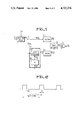
- FIG. 1 shows the block diagram of part of a pulse Doppler radar measuring the ambiguous distance according to the process of the invention
- FIG. 2 shows the signal received after splitting of a reception window
- FIGS. 3a to 3c show the characteristic of the measured ambiguous distance as a function of the position of the pulse received.
- r(t) denotes the signal reflected by the target (not shown) and received by the radar antenna (not shown), the signal transmitted by the radar being a pulse signal e(t) at the constant repetition frequency f R .
- the signal r(t) received by the antenna undergoes at first time splitting into a "sum" channel signal R 1 (t) and a “distance” channel signal R 2 (t) in a circuit 1 controlled by an external signal Sx.
- This circuit can be, for example, a switch.
- This splitting makes it possible to obtain a reception window which may or may not be adapted to the pulse transmitted, an adapted reception window being of the same width as the pulse transmitted and having an optimized signal-to-nose ratio.
- phase difference existing between the principal line and a side line of order p represents the ambiguous distance of the target detected.
- a phase difference can easily be measured between signals of the same frequency. Consequently, either the frequency of the side line of order p is transposed to the frequency of the principal line, as in the preferred non-limiting embodiment of FIG. 1, or conversely the frequency of the principal line is transposed to the frequency of the side line of order p.
- a distance channel in addition to the principal reception channel, called the "sum channel”, the “sum” and “distance” channels being respectively fed with the signals R 1 (t) and R 2 (t) resulting from the division between the two channels, at point A, of the signal received and split R(t), and hence having the same frequency spectrum as the latter.
- the spectrum of the signal received and split R 2 (t) is transposed by a frequency pf R .
- One of the two side lines of order p has therefore been transposed to the original frequency f o +f d of the principal line of the signal R 2 (t) and hence to the frequency of the principal line of the signal received R 1 (t) or R(t).
- this transposition of the spectrum of the signal R 2 (t) is effected by the sub-unit 3.
- this sub-unit can consist, an illustrated in FIG. 1, of a circuit 32 multiplying the repetition frequency f R by a positve integer p, and of a SSB-modulating circuit 31 which receives the signal of frequency pf R from the output of the multiplying circuit 32 and the signal R 2 (t) resulting from the division of the signal received and split R(t) between the two "sum” and "distance” reception channels.
- the signal delivered by the transposing sub-unit 3 is denoted by d(t).
- the principal line of the signal R 1 (t), and hence of the signal received r(t), and the transposed side line of order p of the signal R 2 (t), and hence of the signal received r(t), are at the same frequency and are respectively isolated by a narrow band filter denoted by reference numeral 2 for the "sum” channel and by reference numeral 5 for the "distance” channel.
- the filters 2 and 5 are identical and respectively deliver a signal S(t) and a signal D(t) at the same frequency f o +f d , in which f o is the carrier frequency of the signal transmitted and f d the Doppler frequency corresponding to the target detected.
- the signals S(t) and D(t) obtained at the output of the "sum” and “distance” channels respectively are applied at the input of a circuit 6 which measures and delivers their phase difference ⁇ , representing the ambiguous distance.
- This circuit 6 is, for example, a phase detector.
- This signal representative of the phase difference ⁇ is then amplified in a circuit 7 with a gain equal to ##EQU2## if the ambiguous distance is to be expressed in meters, and to ##EQU3## if the ambiguous distance is to be expressed in seconds. This will be explained below in the description.
- the two signals S(t) and D(t) can be digital coded signals.
- the phase difference ⁇ between the two signals S(t) and D(t) is then calculated by the circuit 6 and subsequently multiplied by the factor g or g' to give directly a measurement of the ambiguous distance which can be used immediately in a subsequent digital processing device.
- FIG. 1 operates in the hereabovedescribed manner, reference also being made to FIG. 2, which shows the signal R(t) received by the antenna after time splitting.
- the signal shown is the signal received R(t) after splitting of an adapted reception window by a pulse signal Sx at repetition frequency f R and of pulse width ⁇ .
- the instant corresponding to zero is chosen arbitrarily and the instant corresponding to the middle of one of the pulses forming the signal R(t) is called T.
- the signal R(t) is periodic, it consists of lines at frequencies which are multiples of f R .
- the SSB modulator 31 delivers the distance signal d(t) formed by multiplication of the signal R(t) by a signal of frequency pf R (p ⁇ 1, p being an integer). Breaking it down into a Fourier series therefore gives: ##EQU5##
- the filtering circuit 5 isolates the principal zero-frequency line ##EQU6##
- the second channel or "distance” channel, therefore isolates the lateral line of order p of the signal received, after transposition to the same frequency as the principal line.
- Representing the SSB modulator 31 by the formula e -j2 ⁇ p ⁇ f R t fixes the instant called zero in FIG. 2 at the instant when the phase of the modulator 31 is zero, that is to say when the phase of the transposition signal (of frequency pf R ) is zero.
- the phase difference is obtained in an analogical or digital way by the detector 6.
- phase difference ⁇ is known to within 2 ⁇ .
- ambiguity in the phase difference ⁇ is therefore equal to 2 ⁇ and the following equation can be written:
- phase difference ⁇ can also be expressed by ##EQU7##
- T i.e. the interval of time existing between the instant corresponding to the middle of the pulse processed and the instant zero (when the phase of the SSB-modulator 31 is 0)
- T R 1/f R being the repetition period of the pulses transmitted.
- the phase difference ⁇ is therefore the measurement in seconds of the interval T between the instant zero and the instant corresponding to the middle of the pulse processed, this interval being known with the ambiguity T R /P. This measurement in seconds is also the time taken by the signal transmitted to travel twice the ambiguous distance sought.
- FIGS. 3a and 3b respectively show the pulse transmitted, in the case of a form factor of 1/5 and the reception window with a form factor of 4/5.
- FIG. 3c shows the characteristic of the phase difference ⁇ obtained in this case, the shift in the pulse received R(t) before splitting of the reception window by the circuit 1 being represented on the abscissa x.
- the form factor is small and less than 0.5, only part of the characteristic can be used and the slope of the characteristic is slight.
- the present invention can be applied to the measurement of the ambiguous distances in a pulse Doppler radar having a high repetition frequency.
Abstract
The present invention relates to a process for measuring the ambiguous distance in a pulse Doppler radar of repetition frequency (fR).
The device comprises means (3) for transposing the signal received R(t) by a signal of frequency p·fR, where p is a positive integer; first and second narrow band filtering means (2,5) isolating the principal line of the signal received R(t) and of the transposed signal d(t) respectively, and means (6) for measuring the phase difference (Δφ) which exists between the two filtered signals and which is proportional to the ambiguous distance with a coefficient g.
Description
The present invention relates to a process for measuring the ambiguous distance and to a pulse Doppler radar using such a process.
In a Doppler radar transmitting pulses at a repetition frequency fR the spectrum of the signal transmitted is composed of a principal line at the carrier frequency fo and of side lines situated on either side of the carrier frequency fo at intervals equal to the repetition frequency fR. Compared with the signal transmitted, the signal received has undergone a delay equal to the time taken for the signal transmitted to cover the radar-target-radar distance, and a frequency shift fd due to the Doppler effect. It therefore comprises a principal line at the frequency fo +fd and side lines separated by fR, the repetition frequency.
Some pulse Doppler radars have a distance ambiguity due to the fact that the delay on the signal received compared with the signal transmitted is only known with a modulo equal to the repetition period TR =1/fR. This is the case in particular if the pulse repetition frequency is high. This distance ambiguity can be eliminated by changing the repetition frequency. During an interval of time when the repetition frequency is constant, the radar can only measure the ambiguous distance. The present invention provides a process for measuring the ambiguous distance.
A known process for carrying out this measurement consists in splitting the reception window into two split gates of the same width, and in calculating the ratio ##EQU1## in which P1 and P2 are respectively the power of the output signal of the receiver corresponding to each of the two split gates.
This process has the following two disadvantages:
The characteristic obtained, (i.e. measurement of the ambiguous distance as a function of the ambiguous distance) is not linear around zero.
The characteristic is limited as soon as the absolute value of the ambiguous distance exceeds the product of the speed of light multiplied by a quarter of the width of the pulse transmitted (saturation effect).
The present invention makes it possible to overcome the above disavantages and relates to a process for measuring the ambiguous distance.
One advantage of the present invention is that it gives a linear characteristic of the measurement of the ambiguous distance as a function of the ambiguous distance.
Another advantage of the present invention is that it makes measurement of the ambiguous distance always possible when the pulse received is not totally eclipsed.
Another advantage of the present invention is that it makes it possible, in the case of a formation of several targets, to obtain a linear measurement of the ambiguous distance over the entire reception window, for each of the targets, with an transmission form factor of less than 0.5.
According to the process of the invention for measuring the ambiguous distance in a tracking Doppler radar transmitting pulses at the repetition frequency fR and receiving the signal reflected by the target in a reception window, the phase difference Δφ is measured which exists in the signal received between the principal line and a side line of order p after the latter and the principal line have been transposed to the same frequency and which corresponds to a measurement of the ambiguous distance.
The present invention will be described in greater details with reference to the accompanying drawings, in which:
FIG. 1 shows the block diagram of part of a pulse Doppler radar measuring the ambiguous distance according to the process of the invention;
FIG. 2 shows the signal received after splitting of a reception window; and
FIGS. 3a to 3c show the characteristic of the measured ambiguous distance as a function of the position of the pulse received.
In the block diagram of FIG. 1, the radar operating in the tracking mode, r(t) denotes the signal reflected by the target (not shown) and received by the radar antenna (not shown), the signal transmitted by the radar being a pulse signal e(t) at the constant repetition frequency fR.
In a non limiting analogical embodiment of the invention, the signal r(t) received by the antenna undergoes at first time splitting into a "sum" channel signal R1 (t) and a "distance" channel signal R2 (t) in a circuit 1 controlled by an external signal Sx. This circuit can be, for example, a switch. This splitting makes it possible to obtain a reception window which may or may not be adapted to the pulse transmitted, an adapted reception window being of the same width as the pulse transmitted and having an optimized signal-to-nose ratio.
As already mentioned and as will be shown later, the phase difference existing between the principal line and a side line of order p (situated, as mentioned above, at an interval equal to pfR from the principal line) represents the ambiguous distance of the target detected.
A phase difference can easily be measured between signals of the same frequency. Consequently, either the frequency of the side line of order p is transposed to the frequency of the principal line, as in the preferred non-limiting embodiment of FIG. 1, or conversely the frequency of the principal line is transposed to the frequency of the side line of order p.
This can be achieved by creating an auxiliary reception channel, called a "distance channel", in addition to the principal reception channel, called the "sum channel", the "sum" and "distance" channels being respectively fed with the signals R1 (t) and R2 (t) resulting from the division between the two channels, at point A, of the signal received and split R(t), and hence having the same frequency spectrum as the latter.
In the "distance channel", the spectrum of the signal received and split R2 (t) is transposed by a frequency pfR. One of the two side lines of order p has therefore been transposed to the original frequency fo +fd of the principal line of the signal R2 (t) and hence to the frequency of the principal line of the signal received R1 (t) or R(t).
This transposition of the spectrum of the signal R2 (t) is effected by the sub-unit 3. In a non-limitating embodiment, this sub-unit can consist, an illustrated in FIG. 1, of a circuit 32 multiplying the repetition frequency fR by a positve integer p, and of a SSB-modulating circuit 31 which receives the signal of frequency pfR from the output of the multiplying circuit 32 and the signal R2 (t) resulting from the division of the signal received and split R(t) between the two "sum" and "distance" reception channels. The signal delivered by the transposing sub-unit 3 is denoted by d(t).
The principal line of the signal R1 (t), and hence of the signal received r(t), and the transposed side line of order p of the signal R2 (t), and hence of the signal received r(t), are at the same frequency and are respectively isolated by a narrow band filter denoted by reference numeral 2 for the "sum" channel and by reference numeral 5 for the "distance" channel. The filters 2 and 5 are identical and respectively deliver a signal S(t) and a signal D(t) at the same frequency fo +fd, in which fo is the carrier frequency of the signal transmitted and fd the Doppler frequency corresponding to the target detected.
The signals S(t) and D(t) obtained at the output of the "sum" and "distance" channels respectively are applied at the input of a circuit 6 which measures and delivers their phase difference Δφ, representing the ambiguous distance. This circuit 6 is, for example, a phase detector.
This signal representative of the phase difference Δφ is then amplified in a circuit 7 with a gain equal to ##EQU2## if the ambiguous distance is to be expressed in meters, and to ##EQU3## if the ambiguous distance is to be expressed in seconds. This will be explained below in the description.
In another embodiment (not shown), the two signals S(t) and D(t) can be digital coded signals. The phase difference Δφ between the two signals S(t) and D(t) is then calculated by the circuit 6 and subsequently multiplied by the factor g or g' to give directly a measurement of the ambiguous distance which can be used immediately in a subsequent digital processing device.
The device shown in FIG. 1 operates in the hereabovedescribed manner, reference also being made to FIG. 2, which shows the signal R(t) received by the antenna after time splitting.
In FIG. 2, the signal shown is the signal received R(t) after splitting of an adapted reception window by a pulse signal Sx at repetition frequency fR and of pulse width τ.
The instant corresponding to zero is chosen arbitrarily and the instant corresponding to the middle of one of the pulses forming the signal R(t) is called T. As the signal R(t) is periodic, it consists of lines at frequencies which are multiples of fR.
Breaking it down into a Fourier series leads to the following representation: ##EQU4##
In the device of FIG. 1, the filter 2 isolating the zero-frequency line of the signal R(t) delivers the signal S(t)=Zo=τ/TR.
In the second ("distance") channel of the device of FIG. 1, the SSB modulator 31 delivers the distance signal d(t) formed by multiplication of the signal R(t) by a signal of frequency pfR (p≧1, p being an integer). Breaking it down into a Fourier series therefore gives: ##EQU5##
The filtering circuit 5 isolates the principal zero-frequency line ##EQU6##
The second channel, or "distance" channel, therefore isolates the lateral line of order p of the signal received, after transposition to the same frequency as the principal line.
In the above calculation, it has been assumed that the signal received has a carrier frequency equal to zero, which makes it possible not to take the microwave phase of the signal into account. However, it is to show that this does not prejudice the generalization of the calculation.
Representing the SSB modulator 31 by the formula e-j2πp·f Rt fixes the instant called zero in FIG. 2 at the instant when the phase of the modulator 31 is zero, that is to say when the phase of the transposition signal (of frequency pfR) is zero.
If, in the expression of D(t), sin (pπ·fR τ) is positive that is to say if p is a positive integer between (2a/b) and (2a+1/b), a being a natural integer and b=τ/TR the form factor of the pulse transmitted, the phase difference Δφ between S(t) and D(t) (which are at the same frequency) is equal to:
Δφ=φ[S(t)]-φ[D(t)]=0-(-2πp·f.sub.R T)=2πp·f.sub.R T.
If sin (p·π·fR τ) is negative that is to say if the positive integer p is between (2a-1/b) and (2a/b), the phase difference is given by Δφ=2πpfR T+π.
The reasoning is identical in both cases of a positive sin and a negative sin and is indicated below in the case of a positive sin.
The phase difference is obtained in an analogical or digital way by the detector 6.
Generally speaking a phase is known to within 2π. The ambiguity in the phase difference Δφ is therefore equal to 2π and the following equation can be written:
Δφ=2πp·f.sub.R T+q·2π
in which q is a relative integer.
The phase difference Δφ can also be expressed by ##EQU7##
The ambiguity in T, i.e. the interval of time existing between the instant corresponding to the middle of the pulse processed and the instant zero (when the phase of the SSB-modulator 31 is 0), is therefore equal to (1/p·fR) or alternatively to TR /p, TR =1/fR being the repetition period of the pulses transmitted. From expression (1), we therefore have ##EQU8##
Multiplied by the coefficient ##EQU9## the phase difference Δφ is therefore the measurement in seconds of the interval T between the instant zero and the instant corresponding to the middle of the pulse processed, this interval being known with the ambiguity TR /P. This measurement in seconds is also the time taken by the signal transmitted to travel twice the ambiguous distance sought.
Multiplied by the coefficient ##EQU10## the phase difference Δφis therefore the measurement y in seconds of the ambiguous distance.
With the speed of light denoted by c, the measurement y of the ambiguous distance which is travelled during an interval of time T'=T/2=g/2·Δφ is therefore equal to ##EQU11## Multiplied by the coefficient ##EQU12## the phase difference Δφ is therefore the measurement y in meters of the ambiguous distance.
FIGS. 3a and 3b respectively show the pulse transmitted, in the case of a form factor of 1/5 and the reception window with a form factor of 4/5.
FIG. 3c shows the characteristic of the phase difference Δφ obtained in this case, the shift in the pulse received R(t) before splitting of the reception window by the circuit 1 being represented on the abscissa x.
It can be seen that for |x|>3/5×T R/ 2 the pulse is truncated by the splitting, and, consequently, the middle of the pulse processed cannot be confused with the middle of the pulse received. There is therefore a break in slope of the characteristic at its ends.
For |x|≦3/5×T R 2, the characteristic is perfectly linear.
In general, the reception form factor is very similar to the transmission form factor, so that the signal-to-noise ratio is a maximum, and it is possible in most cases to take p=1, that is to say to use the first side line of the spectrum.
However, if the form factor is small and less than 0.5, only part of the characteristic can be used and the slope of the characteristic is slight.
To overcome this disadvantage, a harmonic of higher order p of fR is used in this case rather than the first side line of the spectrum (p=1), so as to multiply the slope of the characteristic by p, according to the explanations given above in the general case of processing of the side line of order p.
The present invention has the following advantages:
When estimating the non-ambiguous distance of a target from the successive measurements of the ambiguous distance which are obtained for various values of the repetition frequency, it is not necessary to correct the measurements by calculation, since the characteristic obtained is linear.
Furthermore, it is always possible to measure the ambiguous distance provided that the pulse is not totally eclipsed. In fact, when the pulse is partially eclipsed the slope of the characteristic is divided by two. As the resulting curve remains strictly monotonous, this effect can be compensated.
If a formation of several targets appears, their distances from the radar are not equal. To be able to process them simultaneously, it is then necessary to use a much wider reception window than the pulse transmitted with a form factor of less than 0.5. The device in FIG. 1 makes it possible, for each of the targets, to obtain a measurement of ambiguous distance which is linear over the whole reception window.
The present invention can be applied to the measurement of the ambiguous distances in a pulse Doppler radar having a high repetition frequency.
Claims (9)
1. A process for measuring the ambiguous distance in a tracking Doppler radar transmitting pulses at a repetition frequency fR, and receiving signals reflected by a target in a reception window, comprising successively:
a first step of transposing to a same frequency the principal line and a side line of order p in the frequency spectrum of the received signal, p being a positive integer;
a second step of measuring the phase difference between the transposed principal and side lines at the same frequency; and
a third step of multiplying the phase difference measured by a coefficient for providing a measurement of the ambiguous distance corresponding to the target.
2. A process according to claim 1, wherein the phase difference is multiplied by coefficient ##EQU13## in order to express the ambiguous distance in seconds, or by coefficient ##EQU14## where c is the speed of light, in order to express the ambiguous distance in meters.
3. A process according to claim 1, wherein the step of transposing the phase difference comprises the following operations carried out in succession:
separating the received signal into first and second parallel processing channels;
on the second processing channel, transposing the signal received by a signal of frequency p·fR ;
on the first and second processing channels, narrow band filtering in order to isolate the principal line of the untransposed signal received and of the transposed signal received, respectively;
the phase difference of both principal lines being proportional to the ambiguous distance.
4. A process according to claim 1, wherein the side line of order p is transposed to the frequency of the principal line of the signal received.
5. A process according to claim 1, wherein the frequency of the principal line of the signal received is transposed to the frequency of the side line of order p.
6. A Doppler radar transmitting pulses at a repetition frequency fR by means of an antenna and receiving, by means of the same antenna, the signal reflected by the target and split by a reception window, further comprising:
means for transposing a side line of order p, p being a positive integer, and the principal line of the signal received to a same frequency,
first and second narrow band filtering means for isolating respectively the principal line of the signals which are delivered by the transposing means, and with which they are respectively supplied;
means for measuring the phase difference existing between the signals at the same frequency delivered by the first and second filtering means and delivering a signal (Δφ) whose amplitude is proportional to the ambiguous distance of the target.
7. A pulse Doppler radar according to claim 6, wherein it further comprises means for multiplying the output signal of the measuring means by a coefficient ##EQU15## and delivering a measurement in seconds of the ambiguous distance of the target.
8. A pulse Doppler radar according to claim 6, wherein the transposing means comprises:
a circuit for multiplying the repetition frequency (fR) of the transmitted pulses by a factor p, p being an integer greater than or equal to 1; and
a single-side-band modulator receiving at a first input, the signal received and at a second input the pulse signal of repetition frequency (p·fR) from the output of the multiplying circuit.
9. A pulse Doppler radar according to claim 6, wherein the measuring means consists of a phase detector.
Applications Claiming Priority (2)
| Application Number | Priority Date | Filing Date | Title |
|---|---|---|---|
| FR8221226 | 1982-12-17 | ||
| FR8221226A FR2599854B1 (en) | 1982-12-17 | 1982-12-17 | METHOD FOR MEASURING THE AMBIGUOUS DISTANCE AND PULSE DOPPLER RADAR USING SUCH A METHOD |
Publications (1)
| Publication Number | Publication Date |
|---|---|
| US4727376A true US4727376A (en) | 1988-02-23 |
Family
ID=9280233
Family Applications (1)
| Application Number | Title | Priority Date | Filing Date |
|---|---|---|---|
| US06/561,830 Expired - Fee Related US4727376A (en) | 1982-12-17 | 1983-12-13 | Process for measuring the ambiguous distance and pulse Doppler radar using such a process |
Country Status (7)
| Country | Link |
|---|---|
| US (1) | US4727376A (en) |
| CA (1) | CA1247215A (en) |
| DE (1) | DE3345429A1 (en) |
| FR (1) | FR2599854B1 (en) |
| GB (1) | GB2191648B (en) |
| IT (1) | IT1193444B (en) |
| NL (1) | NL8304351A (en) |
Cited By (4)
| Publication number | Priority date | Publication date | Assignee | Title |
|---|---|---|---|---|
| US6638226B2 (en) | 2001-09-28 | 2003-10-28 | Teratech Corporation | Ultrasound imaging system |
| US20050017892A1 (en) * | 2002-09-10 | 2005-01-27 | Jean-Paul Artis | Method for increasing the unambiguous distance in FSK radars |
| US20090034795A1 (en) * | 2006-02-08 | 2009-02-05 | Thales | Method for geolocalization of one or more targets |
| US20110001823A1 (en) * | 2007-10-26 | 2011-01-06 | Thales | Method for Detecting a Target |
Families Citing this family (1)
| Publication number | Priority date | Publication date | Assignee | Title |
|---|---|---|---|---|
| AU662878B3 (en) * | 1993-11-17 | 1995-09-14 | Laurence Frederick Uchtman | Personal support apparatus |
Citations (1)
| Publication number | Priority date | Publication date | Assignee | Title |
|---|---|---|---|---|
| US3798643A (en) * | 1972-06-27 | 1974-03-19 | Us Air Force | Pulsed doppler radar |
Family Cites Families (3)
| Publication number | Priority date | Publication date | Assignee | Title |
|---|---|---|---|---|
| US3023409A (en) * | 1956-03-09 | 1962-02-27 | Westinghouse Electric Corp | Pulse doppler radar system |
| US3975729A (en) * | 1957-05-31 | 1976-08-17 | Aeronutronic Ford Corporation | Target detecting system |
| US3333266A (en) * | 1966-03-23 | 1967-07-25 | Motorola Inc | Dual spectrum radar ranging |
-
1982
- 1982-12-17 FR FR8221226A patent/FR2599854B1/en not_active Expired
-
1983
- 1983-12-13 US US06/561,830 patent/US4727376A/en not_active Expired - Fee Related
- 1983-12-14 IT IT68301/83A patent/IT1193444B/en active
- 1983-12-15 DE DE3345429A patent/DE3345429A1/en not_active Withdrawn
- 1983-12-15 GB GB08333408A patent/GB2191648B/en not_active Expired
- 1983-12-16 CA CA000443468A patent/CA1247215A/en not_active Expired
- 1983-12-19 NL NL8304351A patent/NL8304351A/en not_active Application Discontinuation
Patent Citations (1)
| Publication number | Priority date | Publication date | Assignee | Title |
|---|---|---|---|---|
| US3798643A (en) * | 1972-06-27 | 1974-03-19 | Us Air Force | Pulsed doppler radar |
Cited By (7)
| Publication number | Priority date | Publication date | Assignee | Title |
|---|---|---|---|---|
| US6638226B2 (en) | 2001-09-28 | 2003-10-28 | Teratech Corporation | Ultrasound imaging system |
| US7223242B2 (en) | 2001-09-28 | 2007-05-29 | Teratech Corporation | Ultrasound imaging system |
| US20050017892A1 (en) * | 2002-09-10 | 2005-01-27 | Jean-Paul Artis | Method for increasing the unambiguous distance in FSK radars |
| US6859167B2 (en) * | 2002-09-10 | 2005-02-22 | Thales | Method for increasing the unambiguous distance in FSK radars |
| US20090034795A1 (en) * | 2006-02-08 | 2009-02-05 | Thales | Method for geolocalization of one or more targets |
| US8107684B2 (en) | 2006-02-08 | 2012-01-31 | Thales | Method for geolocalization of one or more targets |
| US20110001823A1 (en) * | 2007-10-26 | 2011-01-06 | Thales | Method for Detecting a Target |
Also Published As
| Publication number | Publication date |
|---|---|
| FR2599854A1 (en) | 1987-12-11 |
| IT8368301A0 (en) | 1983-12-14 |
| GB8333408D0 (en) | 1987-10-07 |
| DE3345429A1 (en) | 1988-02-11 |
| IT1193444B (en) | 1988-06-22 |
| FR2599854B1 (en) | 1988-10-14 |
| GB2191648A (en) | 1987-12-16 |
| NL8304351A (en) | 1987-11-02 |
| GB2191648B (en) | 1988-05-25 |
| CA1247215A (en) | 1988-12-20 |
Similar Documents
| Publication | Publication Date | Title |
|---|---|---|
| US6646587B2 (en) | Doppler radar apparatus | |
| US4743110A (en) | Laser telemetry and Doppler measurement system with pulse compression | |
| US4388622A (en) | Double sideband linear frequency modulation system for radar applications | |
| US4176351A (en) | Method of operating a continuous wave radar | |
| US4137532A (en) | VIP doppler filter bank signal processor for pulse doppler radar | |
| US5376939A (en) | Dual-frequency, complementary-sequence pulse radar | |
| US5559518A (en) | Low target velocity interferometric AMTI radar | |
| US4333080A (en) | Signal processor | |
| US4625207A (en) | Surface acoustic wave passive transponder having amplitude and phase-modifying surface pads | |
| EP0138940B1 (en) | Method and apparatus for measuring the distance to an object | |
| US6184820B1 (en) | Coherent pulse radar system | |
| US4379295A (en) | Low sidelobe pulse compressor | |
| US5455588A (en) | Method for determining target velocity by measuring phase shift | |
| US5731782A (en) | Ranging systems | |
| US3798590A (en) | Signal processing apparatus including doppler dispersion correction means | |
| EP4206734A1 (en) | Radar detection method and related apparatus | |
| US4566011A (en) | Palindromic polyphase code expander-compressor | |
| US5559516A (en) | Dual cancellation interferometric AMTI radar | |
| US4709237A (en) | Device for eliminating low frequency noise from a transmission system, in particular 1/f noise in a homodyne radar receiver | |
| US5212489A (en) | Echo ranging system for detecting velocity of targets using composite doppler invariant transmissions | |
| US4727376A (en) | Process for measuring the ambiguous distance and pulse Doppler radar using such a process | |
| US5347281A (en) | Frequency-coded monopulse MTI | |
| US4972194A (en) | Method and device for compensating for the speed of clutter in a coherent doppler radar with variable blind speed | |
| AU603704B2 (en) | Fm-cw radar apparatus | |
| US3769585A (en) | Method and apparatus for earth-space range measurements employing correction for ionospheric group delay |
Legal Events
| Date | Code | Title | Description |
|---|---|---|---|
| AS | Assignment |
Owner name: THOMSON-CSF 173, BL. HAUSSMANN 75008 PARIS, FRANCE Free format text: ASSIGNMENT OF ASSIGNORS INTEREST.;ASSIGNOR:PRENAT, MICHEL;REEL/FRAME:004208/0396 Effective date: 19830923 |
|
| REMI | Maintenance fee reminder mailed | ||
| LAPS | Lapse for failure to pay maintenance fees | ||
| FP | Lapsed due to failure to pay maintenance fee |
Effective date: 19920223 |
|
| STCH | Information on status: patent discontinuation |
Free format text: PATENT EXPIRED DUE TO NONPAYMENT OF MAINTENANCE FEES UNDER 37 CFR 1.362 |