US4745972A - Well packer having extrusion preventing rings - Google Patents
Well packer having extrusion preventing rings Download PDFInfo
- Publication number
- US4745972A US4745972A US07/060,564 US6056487A US4745972A US 4745972 A US4745972 A US 4745972A US 6056487 A US6056487 A US 6056487A US 4745972 A US4745972 A US 4745972A
- Authority
- US
- United States
- Prior art keywords
- ring
- packing element
- packer
- planar surface
- extrusion
- Prior art date
- Legal status (The legal status is an assumption and is not a legal conclusion. Google has not performed a legal analysis and makes no representation as to the accuracy of the status listed.)
- Expired - Fee Related
Links
Images

Classifications
-
- E—FIXED CONSTRUCTIONS
- E21—EARTH DRILLING; MINING
- E21B—EARTH DRILLING, e.g. DEEP DRILLING; OBTAINING OIL, GAS, WATER, SOLUBLE OR MELTABLE MATERIALS OR A SLURRY OF MINERALS FROM WELLS
- E21B33/00—Sealing or packing boreholes or wells
- E21B33/10—Sealing or packing boreholes or wells in the borehole
- E21B33/12—Packers; Plugs
- E21B33/1208—Packers; Plugs characterised by the construction of the sealing or packing means
- E21B33/1216—Anti-extrusion means, e.g. means to prevent cold flow of rubber packing
Definitions
- the present invention relates to well tools used in subterranean oil and gas wells under elevated conditions of temperature and pressure and, specifically, to the packing element systems employed on such well tools.
- Downhole well tools of the type under consideration are used to maintain sealing integrity between inner and outer concentric conduits in subterranean wells.
- downhole well packers are commonly used to establish a seal in the annulus between the well casing and a smaller diameter production tubing string inserted into the casing.
- Permanent well packers can be set at a desired location within the well bore by means of mechanical tubing or wireline manipulation or by the use of hydraulic pressure. Once the permanent packer has been set at the prescribed location within the well, it can only be removed by milling or drilling the packer.
- Retrievable packers can be set by hydraulic or mechanical manipulation but can later be retrieved to the well surface.
- Permanent packers are typically utilized at higher temperatures and pressures than comparable retrievable packers. Both permanent and retrievable packers are normally inserted within a well bore with adequate clearance between the packer and the well bore to avoid interference during installation. When the packer is set, radially expandable slips are actuated and move into engagement with the well casing.
- An annular seal or packing element which is typically formed of a resilient, elastomeric material, is carried about a tubular mandrel and is expanded into engagement with the well casing in response to axial compression exerted on the packing element. The clearance between the packer mandrel and the expander surfaces and between the packer mandrel and the well casing provides an annular area into which the packing element, subjected to axial compression, can extrude.
- permanent packers In order to resist extrusion, permanent packers typically employ retaining or backup rings formed of a malleable metallic material. These rings are expandable into engagement with the casing upon the application of an axially compressive force sufficient to expand the packing element into the sealing engagement with the casing. The purpose of these rings is to seal off the annular clearance area to prevent extrusion of the packing material under extreme temperature and pressure conditions.
- An object of the present invention is to provide a well packer having an improved extrusion preventing ring design which resists bending and deformation under extreme conditions of temperature and pressure.
- Another object of the invention is to provide an improved ring design which more effectively fills the annular space between the packer mandrel and the well casing than did prior designs.
- the well packer of the invention is used to maintain sealing integrity between inner and outer concentric conduits under downhole temperature and pressure conditions in a subterranean well.
- the packer includes an annular packing element which is radially expandable under axial compression.
- Upper and lower annular shoulders are disposed on opposite sides of the packing element and at least one of the shoulders is movable axially towards and away from the other shoulder.
- An extrusion preventing device is located between each shoulder and the packing element.
- the extrusion preventing device includes an outer spilt ring having a generally triangular cross-section defined by a cylindrical abutment surface for abutment with the inner surface of the outer conduit, a tapered sidewall engageable with one of the shoulders, and a planar surface which substantially normal to the longitudinal axis of the packer.
- the planar surface has an innermost radial extent which joins the tapered sidewall and an outermost radial extent which joins the cylindrical abutment surface.
- the extrusion preventing device also includes an inner split ring of complementary shape but reversely arranged to the outer ring.
- the planar surface of the inner ring is provided with a circumferential land which joins the innermost radial extent thereof for engaging the innermost radial extent of the outer ring to prevent extrusion of the packing element past the extrusion preventing member.
- FIG. 1 is a side view, partly in section of the well packer of the invention showing the extrusion preventing rings in the relaxed state.
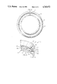
- FIG. 2 is a top, perceptive view of the inner extrusion preventing ring used in the well packer of FIG. 1.
- FIG. 3 is a partial, perspective view of the extrusion preventing device showing the outer and the inner split rings.
- the packer also has an annular packing element 21 of a resilient, elastomeric type material and upper and lower relatively axially shiftable annular shoulders 23, 25 disposed on opposite sides of the packing element 21. At least one of the shoulders 23, 25 is movable towards and away from the other shoulder.
- the annular shoulders 23, 25 form a part of the cone elements of the well packer 11, the cone elements having tapered expander surfaces 27, 29 for causing outward radial movement of the serrated slips 31, 33.
- the lower slip 33 rests upon an end ring 39 which threadedly engages the lower extent 41 of the tubular mandrel 13.
- a setting sleeve 35 is connected to the running tool. Actuation of the running tool, as will be understood by those skilled in the art, results in relative movement between the setting sleeve 35 and the tubular mandrel 13. This relative movement shears the screws 37, 39, thereby compressing the packing element 21 and allowing the outer radial expansion of the gripping slips 31, 33.
- An extrusion preventing device 43, 45 is located between each shoulder 23, 25 and the packing element 21.
- the extrusion preventing devices are radially expandable into abutment with the inner surface 47 of the outer conduit (casing) upon movement of the first and second shoulders 23, 25 toward each to compress the packing element.
- each extrusion preventing device 43 includes an outer split ring 49 having a generally triangular cross-section defined by a cylindrical abutment surface 51 for abutment with the inner surface 47 of the outer conduit, a tapered sidewall 53 engageable with one of the shoulders 23, and a planar surface 55 which is substantially normal to the longitudinal axis 57 of the packer.
- the planar surface 55 has an innermost radial extent 59 which joins the tapered sidewall 53 and an outermost radial extent 61 which joins the cylindrical abutment surface 51.
- the extrusion preventing device 43 also includes an inner split ring 63 which is reversely arranged to the outer ring 49.
- the inner ring 63 also has a generally triangular cross-section defined by a cylindrical abutment surface 65 which is continuous with the surface 51 for abutment with the inner surface 47 of the outer conduit, a tapered sidewall 67 engageable with the packing element 21, and a planar surface 69 having an innermost radial extent 71 which joins the tapered sidewalls 67 and an outermost radial extent 73 which joins the cylindrical abutment surface 65.
- the ring planar surfaces 55, 69 are keyed to one another for circumferential sliding movement.
- the ring planar surfaces 55, 69 are keyed by means of a tongue and groove arrangement such as circumferential rib 75 on inner ring 63 and circumferential groove 77 provided in outer ring 49.
- the rings are each split at and axial location (79 in FIG. 2) and tend to remain in a retracted position, such as that shown in FIG. 1.
- the splits in the upper and lower rings 49, 63 are staggered with respect to one another and are preferably displaced approximately 180° from one another when the rings are assembled. Because of the circumferential rib and groove arrangement and because of the split 79, the rings 49, 63 are expandable outwardly to bring their outer cylindrical surfaces 51, 65 into engagement with the cylindrical inner surface 47 of the surrounding conduit.
- the extrusion preventing rings of the invention are also provided with a circumferential land 81 which helps to prevent extrusion of the packing element 21 past the rings in use.
- the land 81 is provided on the planar surface 69 of the land 81 is provided on the planar surface 69 of the inner split ring 63 and is itself of generally triangular cross-section, extending axially from the planar surface 69 in the direction of the companion shoulder 23.
- one surface 83 of the land 81 is tapered to form a continuous surface with the tapered surface 53 of the outer split ring 49 when the rings are assembled. As shown in FIG.
- the land, together with the circumferential rib 75 forms a channel for receiving a mating portion of the outer ring 49.
- the channel indicated generally at 69 in FIG. 3, has a generally rectangular cross-section with a bottom surface and spaced side walls which are parallel and extend axially with respect to the longitudinal axis 57 of the packer.
- One of the side walls 85 is defined by the circumferential land 81 and the other side wall 87 is defined by the circumferential rib 75.
- the running tool is actuated to cause relative movement between the setting sleeve 35 and the tubular mandrel 13 of the packer.
- This relative movement shifts the outer parts of the packer to expand the gripping slips 31, 33 radially outward and to expand the packing element 21 and extrusion preventing rings 43, 45 radially outward.
- the extrusion preventing rings 43, 45 are also brought into contact with the surrounding casing.
- the circumferential land 81 seals off against its respective expander shoulder 23, 25 to prevent the extrusion of packing material past the rings.
- the circumferential land also provides a ring design which rings having a point contact at the innermost radial extents.
- the extrusion preventing rings of the invention are stronger than previous designs and less likely to bend or fail in use.
- the extrusion preventing rings of the invention are also more effective in preventing extrusion of the packing element past the rings under extreme temperature and pressure conditions such as are encountered during permanent packer use.
Abstract
Description
Claims (6)
Priority Applications (1)
| Application Number | Priority Date | Filing Date | Title |
|---|---|---|---|
| US07/060,564 US4745972A (en) | 1987-06-10 | 1987-06-10 | Well packer having extrusion preventing rings |
Applications Claiming Priority (1)
| Application Number | Priority Date | Filing Date | Title |
|---|---|---|---|
| US07/060,564 US4745972A (en) | 1987-06-10 | 1987-06-10 | Well packer having extrusion preventing rings |
Publications (1)
| Publication Number | Publication Date |
|---|---|
| US4745972A true US4745972A (en) | 1988-05-24 |
Family
ID=22030307
Family Applications (1)
| Application Number | Title | Priority Date | Filing Date |
|---|---|---|---|
| US07/060,564 Expired - Fee Related US4745972A (en) | 1987-06-10 | 1987-06-10 | Well packer having extrusion preventing rings |
Country Status (1)
| Country | Link |
|---|---|
| US (1) | US4745972A (en) |
Cited By (31)
| Publication number | Priority date | Publication date | Assignee | Title |
|---|---|---|---|---|
| GB2236129A (en) * | 1989-08-31 | 1991-03-27 | Baker Hughes Inc | Sealing assembly for subterranean well packing unit |
| US5103904A (en) * | 1989-08-31 | 1992-04-14 | Baker Hughes Incorporated | Sealing assembly for subterranean well packing unit |
| US5176217A (en) * | 1989-08-31 | 1993-01-05 | Baker Hughes Incorporated | Sealing assembly for subterranean well packing unit |
| US5303774A (en) * | 1992-12-11 | 1994-04-19 | Duhn Oil Tool, Inc. | Ring seal packer |
| US5343946A (en) * | 1993-08-09 | 1994-09-06 | Hydril Company | High pressure packer for a drop-in check valve |
| US5749585A (en) * | 1995-12-18 | 1998-05-12 | Baker Hughes Incorporated | Downhole tool sealing system with cylindrical biasing member with narrow width and wider width openings |
| WO2001006087A1 (en) * | 1999-07-19 | 2001-01-25 | Baker Hughes Incorporated | Extrusion resistant inflatable tool |
| EP0798445A3 (en) * | 1996-03-29 | 2001-05-02 | Halliburton Company | Downwhole packer apparatus and method of limiting packer element extrusion |
| US20020195244A1 (en) * | 2001-06-07 | 2002-12-26 | Coronado Martin P. | Compression set, large expansion packing element for downhole plugs or packers |
| US6666276B1 (en) * | 2001-10-19 | 2003-12-23 | John M. Yokley | Downhole radial set packer element |
| US20040036225A1 (en) * | 2000-12-08 | 2004-02-26 | Ritter Michael G. | Anti-extrusion assembly for a packing element system |
| US20090065191A1 (en) * | 2007-07-18 | 2009-03-12 | Reid Michael A | Support assembly for downhole tool, downhole tool and method |
| WO2009158066A2 (en) * | 2008-06-26 | 2009-12-30 | Baker Hughes Incorporated | Resettable antiextrusion backup system and method |
| US7735549B1 (en) | 2007-05-03 | 2010-06-15 | Itt Manufacturing Enterprises, Inc. | Drillable down hole tool |
| US20100186970A1 (en) * | 2009-01-19 | 2010-07-29 | William Stephen Burnett | Support assembly |
| US7900696B1 (en) | 2008-08-15 | 2011-03-08 | Itt Manufacturing Enterprises, Inc. | Downhole tool with exposable and openable flow-back vents |
| US20110062670A1 (en) * | 2009-09-14 | 2011-03-17 | Baker Hughes Incorporated | Load delayed seal element, system, and method |
| US20110147012A1 (en) * | 2006-11-21 | 2011-06-23 | Swelltec Limited | Downhole Apparatus with a Swellable Support Structure |
| US20120037355A1 (en) * | 2010-08-16 | 2012-02-16 | Baker Hughes Incorporated | Retractable Petal Collet Backup for a Subterranean Seal |
| CN102418492A (en) * | 2011-11-02 | 2012-04-18 | 中国石油集团渤海钻探工程有限公司 | Tie-back plug-in sealing device for horizontal well fracturing |
| US8267177B1 (en) | 2008-08-15 | 2012-09-18 | Exelis Inc. | Means for creating field configurable bridge, fracture or soluble insert plugs |
| US8403036B2 (en) | 2010-09-14 | 2013-03-26 | Halliburton Energy Services, Inc. | Single piece packer extrusion limiter ring |
| US8579023B1 (en) | 2010-10-29 | 2013-11-12 | Exelis Inc. | Composite downhole tool with ratchet locking mechanism |
| US8770276B1 (en) | 2011-04-28 | 2014-07-08 | Exelis, Inc. | Downhole tool with cones and slips |
| US8997859B1 (en) | 2012-05-11 | 2015-04-07 | Exelis, Inc. | Downhole tool with fluted anvil |
| CN104879085A (en) * | 2015-05-26 | 2015-09-02 | 中国石油天然气股份有限公司 | Packer seat sealing pressure determining method and device |
| US9845658B1 (en) | 2015-04-17 | 2017-12-19 | Albany International Corp. | Lightweight, easily drillable or millable slip for composite frac, bridge and drop ball plugs |
| US9995111B2 (en) | 2012-12-21 | 2018-06-12 | Resource Well Completion Technologies Inc. | Multi-stage well isolation |
| CN110593804A (en) * | 2019-10-09 | 2019-12-20 | 太仓优尼泰克精密机械有限公司 | Umbrella type anti-extrusion ring |
| CN112832708A (en) * | 2020-12-31 | 2021-05-25 | 湘潭大学 | Hook type packer for annular pipeline |
| US20220316291A1 (en) * | 2020-03-24 | 2022-10-06 | Ronald van Petegem | Roll-out apparatus, method, and system |
Citations (10)
| Publication number | Priority date | Publication date | Assignee | Title |
|---|---|---|---|---|
| US31978A (en) * | 1861-04-09 | Transmitting motion | ||
| US2921632A (en) * | 1956-03-05 | 1960-01-19 | Baker Oil Tools Inc | Expansible and retractable packing structure |
| US2921633A (en) * | 1956-03-05 | 1960-01-19 | Baker Oil Tools Inc | Packing flow preventing device |
| US3036639A (en) * | 1960-05-02 | 1962-05-29 | Baker Oil Tools Inc | Expandible packing apparatus |
| US3061013A (en) * | 1958-11-21 | 1962-10-30 | Lane Wells Co | Bridging plug |
| US3109493A (en) * | 1962-04-30 | 1963-11-05 | Baker Oil Tools Inc | Subsurface well apparatus with packing structures |
| US3229767A (en) * | 1962-12-31 | 1966-01-18 | Baker Oil Tools Inc | Well packer |
| US4433726A (en) * | 1982-02-18 | 1984-02-28 | Baker Oil Tools, Inc. | Energized packer anchor seal assembly |
| US4611658A (en) * | 1984-09-26 | 1986-09-16 | Baker Oil Tools, Inc. | High pressure retrievable gravel packing apparatus |
| US4688634A (en) * | 1986-01-31 | 1987-08-25 | Dresser Industries, Inc. | Running and setting tool for well packers |
-
1987
- 1987-06-10 US US07/060,564 patent/US4745972A/en not_active Expired - Fee Related
Patent Citations (10)
| Publication number | Priority date | Publication date | Assignee | Title |
|---|---|---|---|---|
| US31978A (en) * | 1861-04-09 | Transmitting motion | ||
| US2921632A (en) * | 1956-03-05 | 1960-01-19 | Baker Oil Tools Inc | Expansible and retractable packing structure |
| US2921633A (en) * | 1956-03-05 | 1960-01-19 | Baker Oil Tools Inc | Packing flow preventing device |
| US3061013A (en) * | 1958-11-21 | 1962-10-30 | Lane Wells Co | Bridging plug |
| US3036639A (en) * | 1960-05-02 | 1962-05-29 | Baker Oil Tools Inc | Expandible packing apparatus |
| US3109493A (en) * | 1962-04-30 | 1963-11-05 | Baker Oil Tools Inc | Subsurface well apparatus with packing structures |
| US3229767A (en) * | 1962-12-31 | 1966-01-18 | Baker Oil Tools Inc | Well packer |
| US4433726A (en) * | 1982-02-18 | 1984-02-28 | Baker Oil Tools, Inc. | Energized packer anchor seal assembly |
| US4611658A (en) * | 1984-09-26 | 1986-09-16 | Baker Oil Tools, Inc. | High pressure retrievable gravel packing apparatus |
| US4688634A (en) * | 1986-01-31 | 1987-08-25 | Dresser Industries, Inc. | Running and setting tool for well packers |
Cited By (51)
| Publication number | Priority date | Publication date | Assignee | Title |
|---|---|---|---|---|
| US5103904A (en) * | 1989-08-31 | 1992-04-14 | Baker Hughes Incorporated | Sealing assembly for subterranean well packing unit |
| US5176217A (en) * | 1989-08-31 | 1993-01-05 | Baker Hughes Incorporated | Sealing assembly for subterranean well packing unit |
| GB2236129A (en) * | 1989-08-31 | 1991-03-27 | Baker Hughes Inc | Sealing assembly for subterranean well packing unit |
| US5303774A (en) * | 1992-12-11 | 1994-04-19 | Duhn Oil Tool, Inc. | Ring seal packer |
| US5343946A (en) * | 1993-08-09 | 1994-09-06 | Hydril Company | High pressure packer for a drop-in check valve |
| FR2708967A1 (en) * | 1993-08-09 | 1995-02-17 | Hydril Co | Internal check valve assembly for a drilled well. |
| US5749585A (en) * | 1995-12-18 | 1998-05-12 | Baker Hughes Incorporated | Downhole tool sealing system with cylindrical biasing member with narrow width and wider width openings |
| EP0798445A3 (en) * | 1996-03-29 | 2001-05-02 | Halliburton Company | Downwhole packer apparatus and method of limiting packer element extrusion |
| GB2370851B (en) * | 1999-07-19 | 2003-10-01 | Baker Hughes Inc | Extrusion resistant inflatable tool |
| GB2370851A (en) * | 1999-07-19 | 2002-07-10 | Baker Hughes Inc | Extrusion resistant inflatable tool |
| US6595283B1 (en) | 1999-07-19 | 2003-07-22 | Baker Hughes Incorporated | Extrusion resistant inflatable tool |
| WO2001006087A1 (en) * | 1999-07-19 | 2001-01-25 | Baker Hughes Incorporated | Extrusion resistant inflatable tool |
| US20040036225A1 (en) * | 2000-12-08 | 2004-02-26 | Ritter Michael G. | Anti-extrusion assembly for a packing element system |
| US20020195244A1 (en) * | 2001-06-07 | 2002-12-26 | Coronado Martin P. | Compression set, large expansion packing element for downhole plugs or packers |
| US6843315B2 (en) * | 2001-06-07 | 2005-01-18 | Baker Hughes Incorporated | Compression set, large expansion packing element for downhole plugs or packers |
| US6666276B1 (en) * | 2001-10-19 | 2003-12-23 | John M. Yokley | Downhole radial set packer element |
| US8408316B2 (en) | 2006-11-21 | 2013-04-02 | Swelltec Limited | Downhole apparatus with a swellable support structure |
| US8584764B2 (en) | 2006-11-21 | 2013-11-19 | Swelltec Limited | Downhole apparatus with a swellable support structure |
| US20110147012A1 (en) * | 2006-11-21 | 2011-06-23 | Swelltec Limited | Downhole Apparatus with a Swellable Support Structure |
| US8151894B2 (en) | 2006-11-21 | 2012-04-10 | Swelltec Limited | Downhole apparatus with a swellable support structure |
| US7735549B1 (en) | 2007-05-03 | 2010-06-15 | Itt Manufacturing Enterprises, Inc. | Drillable down hole tool |
| US20090065191A1 (en) * | 2007-07-18 | 2009-03-12 | Reid Michael A | Support assembly for downhole tool, downhole tool and method |
| US8327929B2 (en) * | 2007-07-18 | 2012-12-11 | Red Spider Technology Limited | Support assembly for downhole tool, downhole tool and method |
| WO2009158066A2 (en) * | 2008-06-26 | 2009-12-30 | Baker Hughes Incorporated | Resettable antiextrusion backup system and method |
| WO2009158066A3 (en) * | 2008-06-26 | 2010-03-11 | Baker Hughes Incorporated | Resettable antiextrusion backup system and method |
| US8127856B1 (en) | 2008-08-15 | 2012-03-06 | Exelis Inc. | Well completion plugs with degradable components |
| US8746342B1 (en) | 2008-08-15 | 2014-06-10 | Itt Manufacturing Enterprises, Inc. | Well completion plugs with degradable components |
| US8267177B1 (en) | 2008-08-15 | 2012-09-18 | Exelis Inc. | Means for creating field configurable bridge, fracture or soluble insert plugs |
| US7900696B1 (en) | 2008-08-15 | 2011-03-08 | Itt Manufacturing Enterprises, Inc. | Downhole tool with exposable and openable flow-back vents |
| US8678081B1 (en) | 2008-08-15 | 2014-03-25 | Exelis, Inc. | Combination anvil and coupler for bridge and fracture plugs |
| US8276678B2 (en) | 2009-01-19 | 2012-10-02 | Red Spider Technology Limited | Support assembly for a deformable sealing element for a downhole tool |
| US20100186970A1 (en) * | 2009-01-19 | 2010-07-29 | William Stephen Burnett | Support assembly |
| US20110062670A1 (en) * | 2009-09-14 | 2011-03-17 | Baker Hughes Incorporated | Load delayed seal element, system, and method |
| US20120037355A1 (en) * | 2010-08-16 | 2012-02-16 | Baker Hughes Incorporated | Retractable Petal Collet Backup for a Subterranean Seal |
| US8393388B2 (en) * | 2010-08-16 | 2013-03-12 | Baker Hughes Incorporated | Retractable petal collet backup for a subterranean seal |
| US8403036B2 (en) | 2010-09-14 | 2013-03-26 | Halliburton Energy Services, Inc. | Single piece packer extrusion limiter ring |
| US8579023B1 (en) | 2010-10-29 | 2013-11-12 | Exelis Inc. | Composite downhole tool with ratchet locking mechanism |
| US8770276B1 (en) | 2011-04-28 | 2014-07-08 | Exelis, Inc. | Downhole tool with cones and slips |
| CN102418492A (en) * | 2011-11-02 | 2012-04-18 | 中国石油集团渤海钻探工程有限公司 | Tie-back plug-in sealing device for horizontal well fracturing |
| US8997859B1 (en) | 2012-05-11 | 2015-04-07 | Exelis, Inc. | Downhole tool with fluted anvil |
| US10584562B2 (en) | 2012-12-21 | 2020-03-10 | The Wellboss Company, Inc. | Multi-stage well isolation |
| US9995111B2 (en) | 2012-12-21 | 2018-06-12 | Resource Well Completion Technologies Inc. | Multi-stage well isolation |
| US9845658B1 (en) | 2015-04-17 | 2017-12-19 | Albany International Corp. | Lightweight, easily drillable or millable slip for composite frac, bridge and drop ball plugs |
| CN104879085A (en) * | 2015-05-26 | 2015-09-02 | 中国石油天然气股份有限公司 | Packer seat sealing pressure determining method and device |
| CN104879085B (en) * | 2015-05-26 | 2017-10-17 | 中国石油天然气股份有限公司 | The determination method and device of packer set pressure |
| CN110593804A (en) * | 2019-10-09 | 2019-12-20 | 太仓优尼泰克精密机械有限公司 | Umbrella type anti-extrusion ring |
| US20220316291A1 (en) * | 2020-03-24 | 2022-10-06 | Ronald van Petegem | Roll-out apparatus, method, and system |
| US20220316292A1 (en) * | 2020-03-24 | 2022-10-06 | Ronald van Petegem | Roll-out apparatus, method, and system |
| US11767725B2 (en) * | 2020-03-24 | 2023-09-26 | Ronald van Petegem | Roll-out apparatus, method, and system |
| CN112832708A (en) * | 2020-12-31 | 2021-05-25 | 湘潭大学 | Hook type packer for annular pipeline |
| CN112832708B (en) * | 2020-12-31 | 2023-08-29 | 湘潭大学 | Hook type packer for annular pipeline |
Similar Documents
| Publication | Publication Date | Title |
|---|---|---|
| US4745972A (en) | Well packer having extrusion preventing rings | |
| US4612985A (en) | Seal assembly for well tools | |
| US4288082A (en) | Well sealing system | |
| US6598672B2 (en) | Anti-extrusion device for downhole applications | |
| US3631926A (en) | Well packer | |
| US5720343A (en) | High temperature, high pressure retrievable packer | |
| US3419079A (en) | Well tool with expansible anchor | |
| US3306362A (en) | Permanently set bridge plug | |
| US6772844B2 (en) | High pressure sealing apparatus and method | |
| US5253705A (en) | Hostile environment packer system | |
| US4372393A (en) | Casing bore receptacle | |
| US4438933A (en) | Hydraulic set high temperature isolation packer | |
| US3029873A (en) | Combination bridging plug and combustion chamber | |
| US5211226A (en) | Metal-to-metal seal for oil well tubing string | |
| EP2017432B1 (en) | Support assembly for downhole tool, downhole tool and method | |
| US5101897A (en) | Slip mechanism for a well tool | |
| US4754814A (en) | Well packer with internally adjustable shear release mechanism | |
| US6612372B1 (en) | Two-stage downhole packer | |
| US2921633A (en) | Packing flow preventing device | |
| US3131764A (en) | High temperature packer for well bores | |
| US5390738A (en) | Inflatable packer inner bladder retention and seal | |
| US3695352A (en) | Retrievable well packer apparatus | |
| US3520361A (en) | Well packer with slip and drag block assembly | |
| US5044433A (en) | Pack-off well apparatus with straight shear release | |
| US3684010A (en) | Selectively-anchored well tools |
Legal Events
| Date | Code | Title | Description |
|---|---|---|---|
| AS | Assignment |
Owner name: HUGHES TOOL COMPANY, P.O. BOX 2539, HOUSTON, TEXAS Free format text: ASSIGNMENT OF ASSIGNORS INTEREST.;ASSIGNOR:BELL, MERLE L.;REEL/FRAME:004739/0721 Effective date: 19870520 Owner name: HUGHES TOOL COMPANY, P.O. BOX 2539, HOUSTON, TEXAS Free format text: ASSIGNMENT OF ASSIGNORS INTEREST.;ASSIGNOR:CORONADO, MARTIN P.;REEL/FRAME:004739/0719 Effective date: 19870520 |
|
| FEPP | Fee payment procedure |
Free format text: PAYOR NUMBER ASSIGNED (ORIGINAL EVENT CODE: ASPN); ENTITY STATUS OF PATENT OWNER: LARGE ENTITY |
|
| FPAY | Fee payment |
Year of fee payment: 4 |
|
| REMI | Maintenance fee reminder mailed | ||
| LAPS | Lapse for failure to pay maintenance fees | ||
| FP | Lapsed due to failure to pay maintenance fee |
Effective date: 19960529 |
|
| STCH | Information on status: patent discontinuation |
Free format text: PATENT EXPIRED DUE TO NONPAYMENT OF MAINTENANCE FEES UNDER 37 CFR 1.362 |