US4746798A - Compact optical wavelength discriminator radiometer - Google Patents
Compact optical wavelength discriminator radiometer Download PDFInfo
- Publication number
- US4746798A US4746798A US06/897,671 US89767186A US4746798A US 4746798 A US4746798 A US 4746798A US 89767186 A US89767186 A US 89767186A US 4746798 A US4746798 A US 4746798A
- Authority
- US
- United States
- Prior art keywords
- wavelength
- wavelength selective
- detectors
- recited
- radiant energy
- Prior art date
- Legal status (The legal status is an assumption and is not a legal conclusion. Google has not performed a legal analysis and makes no representation as to the accuracy of the status listed.)
- Expired - Fee Related
Links
- 230000003287 optical effect Effects 0.000 title claims abstract description 21
- 230000005855 radiation Effects 0.000 claims description 14
- 238000001816 cooling Methods 0.000 claims description 10
- 238000003384 imaging method Methods 0.000 claims description 8
- 238000010276 construction Methods 0.000 claims description 4
- 239000000758 substrate Substances 0.000 claims description 3
- 201000009240 nasopharyngitis Diseases 0.000 claims 2
- 230000005540 biological transmission Effects 0.000 description 10
- 239000000463 material Substances 0.000 description 10
- 238000013461 design Methods 0.000 description 9
- 238000000926 separation method Methods 0.000 description 6
- 229910052782 aluminium Inorganic materials 0.000 description 5
- XAGFODPZIPBFFR-UHFFFAOYSA-N aluminium Chemical compound [Al] XAGFODPZIPBFFR-UHFFFAOYSA-N 0.000 description 5
- PFNQVRZLDWYSCW-UHFFFAOYSA-N (fluoren-9-ylideneamino) n-naphthalen-1-ylcarbamate Chemical compound C12=CC=CC=C2C2=CC=CC=C2C1=NOC(=O)NC1=CC=CC2=CC=CC=C12 PFNQVRZLDWYSCW-UHFFFAOYSA-N 0.000 description 4
- 239000011248 coating agent Substances 0.000 description 4
- 238000000576 coating method Methods 0.000 description 4
- 229910052732 germanium Inorganic materials 0.000 description 4
- GNPVGFCGXDBREM-UHFFFAOYSA-N germanium atom Chemical compound [Ge] GNPVGFCGXDBREM-UHFFFAOYSA-N 0.000 description 4
- 230000003595 spectral effect Effects 0.000 description 4
- 230000004075 alteration Effects 0.000 description 3
- 238000004458 analytical method Methods 0.000 description 3
- 238000013459 approach Methods 0.000 description 3
- 238000004519 manufacturing process Methods 0.000 description 3
- 238000000034 method Methods 0.000 description 3
- 230000035945 sensitivity Effects 0.000 description 3
- 238000012360 testing method Methods 0.000 description 3
- IJGRMHOSHXDMSA-UHFFFAOYSA-N Atomic nitrogen Chemical compound N#N IJGRMHOSHXDMSA-UHFFFAOYSA-N 0.000 description 2
- 229910000661 Mercury cadmium telluride Inorganic materials 0.000 description 2
- 238000001514 detection method Methods 0.000 description 2
- 230000000694 effects Effects 0.000 description 2
- WPYVAWXEWQSOGY-UHFFFAOYSA-N indium antimonide Chemical compound [Sb]#[In] WPYVAWXEWQSOGY-UHFFFAOYSA-N 0.000 description 2
- 239000007788 liquid Substances 0.000 description 2
- 239000005304 optical glass Substances 0.000 description 2
- 239000007787 solid Substances 0.000 description 2
- 238000007514 turning Methods 0.000 description 2
- 239000013585 weight reducing agent Substances 0.000 description 2
- MCMSPRNYOJJPIZ-UHFFFAOYSA-N cadmium;mercury;tellurium Chemical compound [Cd]=[Te]=[Hg] MCMSPRNYOJJPIZ-UHFFFAOYSA-N 0.000 description 1
- 238000004364 calculation method Methods 0.000 description 1
- 238000004590 computer program Methods 0.000 description 1
- 239000004020 conductor Substances 0.000 description 1
- 238000011109 contamination Methods 0.000 description 1
- 238000012937 correction Methods 0.000 description 1
- 230000001419 dependent effect Effects 0.000 description 1
- 238000010586 diagram Methods 0.000 description 1
- 229910003460 diamond Inorganic materials 0.000 description 1
- 239000010432 diamond Substances 0.000 description 1
- 238000007516 diamond turning Methods 0.000 description 1
- 230000008030 elimination Effects 0.000 description 1
- 238000003379 elimination reaction Methods 0.000 description 1
- 238000001914 filtration Methods 0.000 description 1
- 238000005187 foaming Methods 0.000 description 1
- 239000007789 gas Substances 0.000 description 1
- 229910052738 indium Inorganic materials 0.000 description 1
- APFVFJFRJDLVQX-UHFFFAOYSA-N indium atom Chemical compound [In] APFVFJFRJDLVQX-UHFFFAOYSA-N 0.000 description 1
- 239000011261 inert gas Substances 0.000 description 1
- 238000005259 measurement Methods 0.000 description 1
- 229910052757 nitrogen Inorganic materials 0.000 description 1
- 238000012545 processing Methods 0.000 description 1
- 230000000135 prohibitive effect Effects 0.000 description 1
- 238000011160 research Methods 0.000 description 1
- 238000002076 thermal analysis method Methods 0.000 description 1
Images


Classifications
-
- G—PHYSICS
- G02—OPTICS
- G02B—OPTICAL ELEMENTS, SYSTEMS OR APPARATUS
- G02B27/00—Optical systems or apparatus not provided for by any of the groups G02B1/00 - G02B26/00, G02B30/00
- G02B27/10—Beam splitting or combining systems
- G02B27/14—Beam splitting or combining systems operating by reflection only
- G02B27/143—Beam splitting or combining systems operating by reflection only using macroscopically faceted or segmented reflective surfaces
-
- G—PHYSICS
- G01—MEASURING; TESTING
- G01J—MEASUREMENT OF INTENSITY, VELOCITY, SPECTRAL CONTENT, POLARISATION, PHASE OR PULSE CHARACTERISTICS OF INFRARED, VISIBLE OR ULTRAVIOLET LIGHT; COLORIMETRY; RADIATION PYROMETRY
- G01J3/00—Spectrometry; Spectrophotometry; Monochromators; Measuring colours
- G01J3/02—Details
- G01J3/0205—Optical elements not provided otherwise, e.g. optical manifolds, diffusers, windows
- G01J3/0243—Optical elements not provided otherwise, e.g. optical manifolds, diffusers, windows having a through-hole enabling the optical element to fulfil an additional optical function, e.g. a mirror or grating having a throughhole for a light collecting or light injecting optical fiber
-
- G—PHYSICS
- G01—MEASURING; TESTING
- G01J—MEASUREMENT OF INTENSITY, VELOCITY, SPECTRAL CONTENT, POLARISATION, PHASE OR PULSE CHARACTERISTICS OF INFRARED, VISIBLE OR ULTRAVIOLET LIGHT; COLORIMETRY; RADIATION PYROMETRY
- G01J3/00—Spectrometry; Spectrophotometry; Monochromators; Measuring colours
- G01J3/12—Generating the spectrum; Monochromators
-
- G—PHYSICS
- G02—OPTICS
- G02B—OPTICAL ELEMENTS, SYSTEMS OR APPARATUS
- G02B27/00—Optical systems or apparatus not provided for by any of the groups G02B1/00 - G02B26/00, G02B30/00
- G02B27/10—Beam splitting or combining systems
- G02B27/1006—Beam splitting or combining systems for splitting or combining different wavelengths
-
- G—PHYSICS
- G02—OPTICS
- G02B—OPTICAL ELEMENTS, SYSTEMS OR APPARATUS
- G02B27/00—Optical systems or apparatus not provided for by any of the groups G02B1/00 - G02B26/00, G02B30/00
- G02B27/10—Beam splitting or combining systems
- G02B27/14—Beam splitting or combining systems operating by reflection only
- G02B27/148—Beam splitting or combining systems operating by reflection only including stacked surfaces having at least one double-pass partially reflecting surface
-
- G—PHYSICS
- G01—MEASURING; TESTING
- G01J—MEASUREMENT OF INTENSITY, VELOCITY, SPECTRAL CONTENT, POLARISATION, PHASE OR PULSE CHARACTERISTICS OF INFRARED, VISIBLE OR ULTRAVIOLET LIGHT; COLORIMETRY; RADIATION PYROMETRY
- G01J3/00—Spectrometry; Spectrophotometry; Monochromators; Measuring colours
- G01J3/12—Generating the spectrum; Monochromators
- G01J2003/1213—Filters in general, e.g. dichroic, band
-
- G—PHYSICS
- G01—MEASURING; TESTING
- G01J—MEASUREMENT OF INTENSITY, VELOCITY, SPECTRAL CONTENT, POLARISATION, PHASE OR PULSE CHARACTERISTICS OF INFRARED, VISIBLE OR ULTRAVIOLET LIGHT; COLORIMETRY; RADIATION PYROMETRY
- G01J5/00—Radiation pyrometry, e.g. infrared or optical thermometry
- G01J5/60—Radiation pyrometry, e.g. infrared or optical thermometry using determination of colour temperature
- G01J2005/607—Radiation pyrometry, e.g. infrared or optical thermometry using determination of colour temperature on two separate detectors
-
- G—PHYSICS
- G01—MEASURING; TESTING
- G01J—MEASUREMENT OF INTENSITY, VELOCITY, SPECTRAL CONTENT, POLARISATION, PHASE OR PULSE CHARACTERISTICS OF INFRARED, VISIBLE OR ULTRAVIOLET LIGHT; COLORIMETRY; RADIATION PYROMETRY
- G01J3/00—Spectrometry; Spectrophotometry; Monochromators; Measuring colours
- G01J3/28—Investigating the spectrum
- G01J3/30—Measuring the intensity of spectral lines directly on the spectrum itself
- G01J3/36—Investigating two or more bands of a spectrum by separate detectors
-
- G—PHYSICS
- G01—MEASURING; TESTING
- G01J—MEASUREMENT OF INTENSITY, VELOCITY, SPECTRAL CONTENT, POLARISATION, PHASE OR PULSE CHARACTERISTICS OF INFRARED, VISIBLE OR ULTRAVIOLET LIGHT; COLORIMETRY; RADIATION PYROMETRY
- G01J5/00—Radiation pyrometry, e.g. infrared or optical thermometry
- G01J5/02—Constructional details
- G01J5/06—Arrangements for eliminating effects of disturbing radiation; Arrangements for compensating changes in sensitivity
- G01J5/061—Arrangements for eliminating effects of disturbing radiation; Arrangements for compensating changes in sensitivity by controlling the temperature of the apparatus or parts thereof, e.g. using cooling means or thermostats
Definitions
- This invention relates to wavelength discriminator radiometers, and more particularly to devices used to angularly separate two or more wavelengths of interest.
- wavelength discrimination can be accomplished by collecting broadband energy and then isolating specific narrow bands of interest and imaging them onto energy sensors. Narrow band flashes are readily detected because such signals will trigger an electrical current in only one channel of a state of the art device.
- the design approach usually adopted for such a device uses a simple catadioptric afocal telescope to collect and collimate the incoming energy and two dichroic beam splitters to isolate the wavelengths of interest. Typically this is followed by three separate imaging optics, three separate detectors and three separate detector coolers. It obviously would be advantageous to find an efficient technique that would combine the optical paths through a single imaging optic and place the three detectors on a single detector cooler.
- Prior art devices typically utilize a large primary mirror that serves to collect and image the energy from extended sources. The energy is then recollimated to form a classical Newtonian Telescope. Three dichroic beamsplitters are then located in the collimated space separating the three selected wavelengths of interest and sending them to three separate imager optics and to three separate detectors. This solution is straightforward but results in a large, heavy and expensive system.
- an optical wavelength discriminator radiometer that angularly separates two or more wavelengths of interest, and then recombines their paths through a single imager lens such that an appropriate number of separate detectors may advantageously be located on the same cold finger. This is accomplished by a unique arrangement of dichroic plates that both combines the optical paths of the several wavelengths and angularly separates them.
- the detectors may be located on a single detector cooler, but yet they are sufficiently isolated that the signals of each wavelength are imaged onto separate detectors and may thereby be discriminated.
- the resultant system is lighter, smaller, less expensive, and generally more satisfactory than the conventional approach.
- the three detectors must be close enough to be placed on a single cooler but sufficiently separated so that the image at each wavelength can be readily discriminated.
- wavelengths ⁇ 1 and ⁇ 2 are isolated narrow spectral bands and wavelength ⁇ 3 as broadband. If a signal is received by either sensor #1 or sensor #2 and not the #3 sensor, then a narrow band source has been detected. The #3 sensor therefore serves as a guard channel against false alarms.
- detectors can be placed on a single substrate as a result of spacing wavelength selective reflectors closely together and disposed at proper angular relationships. It is to be realized, however, that a wavelength selective reflector or dichroic beamsplitter that reflects one wavelength must also be able to transmit the wavelengths reflected by succeeding dichroic beamsplitters of the array.
- the wavelength selective reflectors (dichroic beamsplitter) we use are dichroic filters and hence have a center reflecting wavelength that shifts with incident angle. Consequently, collimating optics are usually required in order to keep the incident angle as small as possible, and it is to be realized there will always be slight angle variations due to the field of view.
- Another significant aspect of our invention is the used of a field stop, for without the use of this device, light entering the system from outside the designated field of view may impinge on the wrong detector, thus giving rise to a false signal. In applications where the incoming energy will never be out of the designed field of view, the field stop is not required.
- each detector sees the entire field of view.
- the 82% normalized transmission at wavelength ⁇ 3 is calculated by multiplying the normalized transmission of 0.990 for dichroic beamsplitter #3; by 0.970 for beamsplitter #2; and by 0.850 for beamsplitter #1.
- our invention involves a wavelength discriminator designed to collect multiple wavelength input energy, to isolate specific narrow bands of interest, and to image such narrow bands of interest upon closely spaced, discrete detectors.
- Our novel discriminator comprises means for directing incoming radiant energy of a certain quality and involving a wide range of wavelengths through first and second wavelength selective reflectors separated by a medium that transmits the wavelengths of interest.
- our wavelength selective reflectors are disposed in a double pass geometrical arrangement wherein energy reflected from the second wavelength selective reflector passes back through the first wavelength reflector. This novel double pass arrangement makes possible the use of the same imaging system to focus light rays that have been angularly displaced, onto respective detectors that have been spatially separated to a small extent.
- FIG. 1 is a layout of certain principal components of our compact optical wavelength discriminator, with portions shown in cross section to reveal internal construction;
- FIG. 2 is a view similar to FIG. 1 but constructed to a larger scale to reveal the components constituting the heart of our invention, involving three dichroic beamsplitter (filter) plates along with the collimator, imager and detectors, with the approximate ray path from each dichroic filter plate to the respective detector also being shown;
- filter dichroic beamsplitter
- FIG. 3 is a view to a considerably larger scale of a preferred detector arrangement, sealed into a vacuum created behind a dewar window made of material transmissive to all the wavelengths of interest, with cold filters being used to increase signal to noise ratio when low level signals are being discriminated against a noisy background;
- FIG. 4 shows a ray trace drawn with seven rays chosen of the wavelength which reflects off of the center dichroic filter, with all the rays shown focused on the center detector;
- FIG. 5 is a graph showing how the spot size on an outer detector increases in size, measured in mils, with variations in temperature, with it to be noted that most of the spot size variations with temperature fall within the dotted lines representing 10% of the field of view, which criteria was met by this invention;
- FIGS. 6a and 6b are views of simplified alternate embodiments of wavelength selective reflectors in accordance with out invention, set forth in schematic form;
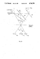
- FIG. 7 shows the angles of the central ray onto each detector, with it to be realized that inasmuch as minimum spacing between detectors varies with different detectors, the corresponding angles vary, which is important in determining the angle at which the dichroic beamsplitter in accordance with our invention must be tilted;
- FIG. 8 shows how the angles calculated in FIG. 7 are used to determine the angles of the dichroic filters, with the center dichroic set at a nominal angle of 45°, and the first and third dichroics tilted so that light in each instance will be caused to fall on the correct detector;
- FIG. 9 shows the spacings that can be used to provide a minimum imager lens size based on the diameter of the collimated beam, with these spacings being measured only from the front surface of each dichroic filter;
- FIG. 10 reveals the information needed by a mechanical designer in constructing a mechanism for tilting the plates at appropriate angles.
- FIG. 1 it will there be seen that we have illustrated a wavelength discriminator radiometer 10 in accordance with a preferred embodiment of this invention.
- the window is anti-reflection coated on both sides and the window is hermetically sealed to the case 13 to keep out dirt and contamination.
- the window must be larger than the collecting aperture so that a desired 1.0 ⁇ 1.0 degree field of view and the desired +/-2.5 degree elevation field of regard are not vignetted.
- a gimballed fold mirror 14 also known as an elevation mirror. Contained in a mid portion of mirror 14 is an aperture 15, directly behind which is a field stop 16. Mechanism 17 permits angular adjustments of the angle of the mirror 14 that are needed in order to adjust the field of regard.
- the requirement for a lightweight system forced the exploration of novel solutions for the large mirror 14, which mirror for example may measure 18 by 13 inches.
- the search resulted in an unusual lightweight mirror material called Foamed Aluminum manufactured by Energy Research Group in San Diego, Calif.
- the material is made by foaming molten aluminum with inert gas and then cooling it.
- the sponge-like material is then milled into the desired shape and solid plates are then brazed to the front and back.
- the front surface of the mirror was diamond turned to a flatness requirement of 1/4 wave at 10 microns.
- the product is extremely lightweight but nevertheless has excellent rigidity so that a quality optical surface can be achieved.
- the mirror 14 we prefer to use weighs only 4.25 pounds when made of foamed aluminum, whereas a solid block of the same dimensions would weight 26 pounds. This weight reduction along with the elimination of two of the original three detector coolers resulted in a net weight reduction of approximately 90 pounds from our overall system.
- parabolic mirror 22 which serves as a suitably large collecting aperture for the system, and focusses the incoming energy at the field stop 16.
- the f/1.25 parabolic mirror 22 we prefer to use is 12 inches in diameter and has a 15" focal length, and it permits a large collection aperture.
- the parabolic shape was achieved by diamond turning an aluminum block. The quality of the mirror 22 insofar as forming a good image was assured by the requirement that the image of a point source formed by the parabola would contain 80 percent of the energy within a 0.001" diameter pinhole.
- the field stop 16 is located at the focal point of the parabola to prevent radiation outside the field of view from impinging on the wrong detector.
- the field stop advantageously restricts the field of view, thereby entirely eliminating the problem associated with the receipt of extraneous radiation.
- FIG. 2 reveals the triplet lens assembly to a larger scale, and for an infra-red system, the elements 19a and 19b are preferably germanium, whereas the element 19c is zinc selenide.
- the lenses may be chosen from a number of suitable standard Schott optical glasses, such as Schott LAK 10 and Schott SF 58 crown-flint combination used in the collimator and imager optical groups. This typical combination enables correction for chromatic aberration.
- the rays of all the wavelengths be well collimated or the tilted dichroic beamsplitter plates that follow may not pass the radiation due to total internal reflection, because the angle variation may be out of the dichroic filter acceptance angle for reflecting the band of interest.
- the collimating optics could be dispensed with.
- a typical acceptance angle for a dichroic filter is about 10°.
- the lenses 19a, 19b and 19c of the collimating triplet lens assembly 18 in conjunction with the parabola 22 may be regarded as forming a 7.2 ⁇ a focal telescope.
- the dichroic beamsplitter plates are plano parallel parts, they have no effect on the aberrations of the system and serve only to separate and direct the wavelengths of interest.
- wavelength selective reflectors in accordance with this invention, these being 26a, and 26b and 26c, as best revealed in FIG. 2.
- the wavelength selective reflectors may also refer to the wavelength selective reflectors as dichroic beamsplitters, or as radiant energy deflecting members.
- the first of these wavelength selective reflectors which is reflector or dichroic beamsplitter 26a, serves to reflect wavelength ⁇ 1 , while permitting the rest of the energy to pass through.
- reflector or dichroic beamsplitter 26b reflects wavelength ⁇ 2 while transmitting the rest of the radiant energy.
- the wavelength ⁇ 2 reflected by reflector 26b transmit through reflector 26a for the second time, as will be noted from FIG. 2. We prefer to call this "double-passing.”
- Each plate of out novel wavelength selective reflectors or dichroic beamsplitters is made of material which will transmit all of the wavelengths of interest, and in most instances, it is the front surface of each dichroic beamsplitter that has the dichroic coating permitting certain wavelengths to pass, and it rear side contains a broadband anti-reflection coating.
- the first two dichroic beamsplitters or reflectors 26a and 26b are made of zinc selenide with a dichroic coating on one side, and a broadband antireflection coating on the other side, whereas reflector 26c is a broadband reflector, that reflects virtually all of the energy incident on it.
- the wavelength selective reflector 26c is an aluminum mirror.
- wavelength ⁇ 3 double passes reflectors 26b and 26a. It is also important to realize that reflector 26b is set at a designated angle, such as an angle of 45°, whereas reflectors 26a and 26c are set at an angle with respect thereto, such that the desired angular separation will be achieved, and so that all three wavelengths are angularly displaced in an advantageous manner.
- the spacing between the plates is set so that the central ray from each of the wavelengths converage at the center of the imager front lens so as to minimize the size of the imager.
- the dichroic beamsplitters we use for the wavelength selective reflectors 26a and 26b pass all the wavelengths involved, and that all three dichroic beamsplitters we use in the preferred embodiment of our invention reflect the three selected narrowband wavelengths.
- the dichroic beamsplitter or wavelength selective reflectors depicted in the preferred embodiment of our invention illustrated in FIGS. 1 and 2 are tilted at different angles so that the optical paths of the three wavelengths are displaced angularly, but are recombined at the aperture of the imager 28, which is made up of three individual lenses 29a, 29b and 29c. While the advantages of size, weight, and cost are apparent, the transmission losses, due to doublepassing the dichroic beamsplitters, could have prohibited a functional design. This likewise was found not to be the case, however, as was shown from the Transmission Analysis set forth in Table 1 hereinabove.
- FIGS. 7 through 10 are illustrative of certain details of our preferred embodiment, wherein the dichroic beamsplitter angles and spacing are determined by the detector spacing and imager focal length.
- the detector spacing determines the angles at which each wavelength must enter the imager, but mechanical considerations of mounting and adjusting the plates (+2.0°) determines how close the dichroic beamsplitters can be placed.
- the imager 28, the second triplet is composed of two germanium lenses and one zinc selenide lens in the preferred embodiment, and focusses the spectrally split energy emerging from the wavelength selective reflectors or dichroic beamsplitters.
- the imager characteristics of this embodiment may be summarized as follows: T1 -Imager focal length 1.25"? -Imager semi-field angle (spectral) 3.66 degrees ⁇ ? - 3.66 degrees -Imager field of view (total) 7.32 ⁇ 26.6 - degrees -Imager aperture size 2.52"? -
- the collimated energy from each wavelength is then imaged by a triple lens imager assembly 28, involving lens components 29a, 29b and 29c, and by virtue of this arrangement, three separate and distinct images are created, one for each wavelength.
- the three separate images are then caused to respectively fall upon detectors 32a, 32b and 32c of the detector array 30.
- the position and separation of the detectors has been exaggerated in FIGS. 1 and 2, and in neither of these figures was it conveniently possible to illustrate to scale, either the size or the positions of the detectors.
- triplets 18 and 28 relay the image of the field stop reduced in size by 0.6 ⁇ .
- the detectors 32a, 32b and 32c are in a manner of speaking perpendicular to the plane of the paper, which confines all the parameters of interest to a single plane. This simplifies both the design and fabrication of the system, but it is to be realized that the dichroic beamsplitter plates may be rotated out of the plane of the paper as well to accommodate more wavelengths or reduce the total effective field of view of the imager. It should be remembered however, that this rotation introduces an image rotation as well.
- narrow band filters 34a and 34b in front of the detectors 32a and 32b.
- detector 32c need not utilize a filter inasmuch as it is the guard channel, and is necessarily sensitive to a wide range of wavelengths.
- a dewar window 42 may be used, which is made of a material that is transmissive to all the wavelengths of interest for an infra-red detection system. Importantly, this window seals in the vacuum in which the detectors 32a, 32b and 32c must be kept for a dewar-cooler arrangement.
- a suitable window material for a mid-infra-red detection system is germanium.
- each detector is sensitive to the specific wavelength of interest that is reflected from the respective dichroic beamsplitters.
- detector 32a ( ⁇ 1 detector) receives energy reflected from dichroic beamsplitter 26a;
- detector 32b ( ⁇ 2 detector) receives energy reflected from the dichroic beamsplitter 26b; and
- detector 32c ( ⁇ 3 detector) receives energy reflected from dichroic beamsplitter 26c.
- the detectors 32a, 32b and 32c selected for this preferred embodiment of this invention are:
- Fabrication constraints set the minimum detector separation. It is important that the detectors be as close together as possible to minimize the apparent field angle of the imager.
- the separation between first detector 32a and the second detector 32b is 0.022 inches, and the separation between the second detector 32b and the third detector 32c is 0.055". It is obvious that we are not to be limited to the use of these particular detectors or to these spacings.
- Narrow band cold filters 34a and 34b are located in front of the first and second detectors, respectively, rejecting everything but the wavelengths of interest.
- the third wavelength ⁇ 3 in the preferred embodiment is broadband, so in this instance, no filter is required.
- Off the shelf cold filters 34a and 34b were procured with different thicknesses, as will shortly be discussed. The height of each detector was designed to compensate for the different optical paths through the cold filters and the residual chromatic aberration of the imager.
- the third detector, detector 32c is different from the other two inasmuch as in the preferred embodiment it must detect broadband wavelengths.
- infrared detectors which gain the maximum sensitivity from being cooled, and most advantageously, only a single cooler will in accordance with this invention be sufficient to cool three detectors.
- the sample platform 44 is connected via a thermally conductive material to a common cooling device, such as a cold finger (not shown) in which a liquid gas such as liquid nitrogen is being pumped.
- a common cooling device such as a cold finger (not shown) in which a liquid gas such as liquid nitrogen is being pumped.
- a cooling substrate as the cooling device.
- the cold filters which are placed in close proximity to the detectors, serve to increase the signal to noise ratio when low level signals are being discriminated against a noisy background.
- the cold filters are optional. Note that since the cold filters are plates which act to shorten the focal length of the signal focused on the detector, that the detectors must be further away from the dewar window if the cold filters are removed.
- the distance between the interior surface of the dewar window 42 and the sample platform 44 is 0.496 inches, whereas distance a between the interior surface of the window 42 and the top of the detector 32a is 0.3721 inches.
- the cold filter 34a in front of the detector 32a is 0.0197 inches thick.
- Distance b between the interior surface of the window 42 and the top of the detector 32b is 0.3994 inches, and the cold filter 34b in front of this detector is 0.030 inches thick.
- Distance c between the front of detector 32c and the interior of the dewar window is 0.3654 inches, and as previously mentioned, no cold filter is utilized in this particular instance, although one may well be used in the event that detector 32c is being used for selective wavelength discrimination.
- the optical design in accordance with the preferred embodiment of our invention was carried out in a modular fashion.
- the parabolic mirror, the collimating triplet and the imager were designed independently on ACCOS V lens design program. These sub-systems were then combined and raytraced, as shown in FIG. 4, to assure compliance with system requirements. This was done by computing spot diagrams of each wavelength at the appropriate field angles. Table 2 summarizes this data, as will now be seen.
- the detectors act as a photon bucket, the spot size on axis and at intermediate points in the field is of little consequence, but it is important that each detector see essentially the same field of view.
- the size of the point spread image at the edges of each detector will determine the apparent variation in field of view.
- Experience with such devices in the past has shown that a point spread image size less than 1/10 the field of view is acceptable.
- Table 2 indicates the minimum size of a spot focused by the imager on each of the detectors, both on axis and at full field of view. If any spot were too large at full field of view, energy could overlap from one detector onto another. This would give a false alarm wavelength signal and hinder the discrimination usefulness.
- FIG. 4 shows a raytrace for the simplest case of our invention, in this instance drawn by the use of an optical design computer program (ACCOSV), with the zero field of view centered on the middle detector, and with all rays passing from the entrance aperture to the detectors.
- ACCOSV optical design computer program
- seven rays were chosen of the wavelength which reflects off of the center dichroic filter 26b. All the rays are shown focused on the center detector, and inasmuch as all seven rays were from the center of the field of view, all rays hit the center of the center detector. Should rays have come from the edge of the field of view, then they would have struck the edge of the center detector.
- a raytrace for light reflecting off of the first dichroic filter would show the rays hitting the lower detector, whereas a raytrace for light reflecting off of the third dichroic filter would show the rays hitting the upper detector.
- FIG. 5 it is to be realized that our system must operate over a large temperature range (-40° to +50° C.) with no active focusing element (passive operation). Consequently, we found it desirable to conduct an optical thermal analysis in order to verify that the system would conform to minimum specifications over that range. This performance specification requires the point spread be no larger than 1/10 the field of view.
- the field of view is one degree (1°) by one degree (1°), which corresponds to 0.157 inches square at the detector plane.
- the spot blur should not grow more than 10% of this detector width, or 15.7 mils. This value has been determined to be the compromise between minimum crosstalk between buildable detectors, and a buildable system.
- FIG. 5 shows that the spot size stays within this criteria if the curve is biased to about 5° C., or in other words, it shows that the system focus must be biased to approximately 5° C. to assure compliance with the performance specification over the entire temperature range.
- FIG. 5 shows how the spot size on an outer detector increases in size as measured in mils (1/1000 inch) with variations in temperature. Spot increases representing 10% of the field of view (i.e., 10% of the detector size) are shown in dotted lines. It is to be noted that most of the spot size variations with temperature fall within these dotted lines (i.e. the spot size rarely increases to more than 10% of the field of view over temperature). Our system was designed to meet this criteria.
- the lens sets of our device are individually checked by sending the collimated output of the interferometer into what would be the collimated output or input of the lens group. This will cause the 10.6 micron radiation to focus down to a point.
- a mirror which is perpendicular to the optical axis is placed at this focal point, thus sending the radiation back through the lens into the interferometer.
- the position of the mirror that achieves parallel fringes in the interferometer is the lens back focal length.
- the radiation passing back through the lens under test then returns into the interferometer to form a fringe pattern from which wavefront distortions are measured. Therefore, back focus, fabrication errors and/or assembly errors may be identified with this simple test.
- FIG. 6a we schematically reveal apparatus for selectively separating predetermined wavelengths or bandwidths of radiant energy from a beam of polychromatic radiant energy, in this instance comprising a first radiant energy deflecting member 36a, otherwise know as a wavelength selective reflector, that is supported in a position of radiant energy deflecting alignment relative to the incoming beam.
- This first deflecting member 36a is arranged to selectively deflect a first wavelength or bandwidth of radiant energy contained in the beam, while permitting the remainder of the beam to pass through.
- the radiant energy reflected from 36a may be arranged to impinge on a detector 38.
- any dichroic beamsplitter is solely determined by the angle of the beamsplitter off which the beam reflects. Subsequent plates only serve to displace the beam laterally and not angularly.
- a second radiant energy deflecting member or wavelength selective reflector 36b is supported in a relatively closely spaced, overlapping alignment with the first deflecting member, and in a position of radiant energy deflecting alignment with respect to the beam after the passage of the beam through the first deflecting member 36a.
- the spacing and alignment between the first and second deflecting members is such that a first part of the radiant energy deflected by the second deflecting member travels along a path through the first deflecting member.
- the second deflecting member may be selected to permit the remainder of the beam to pass through after the first part has been reflected through the first deflecting member 36a.
- the radiant energy reflected from 36b double passes 36a and may then be arranged to impinge upon detector 40.
- the energy deflecting members 36a and 36b can be separated by an air gap, or as illustrated in FIG. 6b, a wavelength refractive material 52 such as optical glass or zinc selenide may be used to separate the first and second deflecting members 46a and 46b, the decision being based upon the spectral band of interest.
- the first deflecting member 46a may for example be coated on one side of the refractive material 52, and the second deflecting member 46b may be coated on the other side of the refractive material.
- the radiant energy reflected from member 46a may be arranged to impinge upon detector 48, whereas the radiant energy reflected from member 46b may be arranged to impinge upon detector 50.
- FIG. 7 shows the angles of the central ray onto each detector, with detectors 32a, 32b and 32c being in the same relationship as depicted hereinbefore in FIG. 3. We obviously are not to be limited to the physical separation distances called out in this figure. Because the minimum spacing between the detectors for this embodiment varied due to our using different detectors, the corresponding angles are necessarily different.
- the focal length of the detector imager lens set is 1.252"
- the angles ⁇ 1 and ⁇ 2 are the inverse tangent of the distance from the center of the center detector to the center of the respective outermost detector divided by the imager focal length.
- This chief ray exit angle from the imager approximates the chief ray acceptance angle into the imager.
- FIG. 8 shows how the angles calculated in FIG. 7 are used to determine the angles of the dichroic beamsplitters, thus taking into consideration the size and spacing of the selected detectors.
- the dichroic beamsplitters are presumed to be infinitely thin.
- the nominal tilt angle is 45° and the center dichroic beamsplitter 26b is set at this angle. Since reflectors cause angle doubling, the first dichroic beamsplitter 26a and third dichroic beamsplitter 26c are tilted 45++ ⁇ 2 /2 and 45°- ⁇ 1 /2 respectively.
- plate 26a will be tilted at 45° plus half the chief ray acceptance angle
- plate 26c will be tilted at 45° minus half the chief ray acceptance angle.
- the angle ⁇ 1 of 26a to be 49.077°
- the angle ⁇ 2 of 26c is 40.186°, with detector spacing and size being of course the limiting factor.
- the horizontal line through the vertex located in the center portion of FIG. 8 represents the middle of the first lens front surface.
- FIG. 9 shows the spacings that can be used to provide a minimum imager lens size based on the diameter of the collimated beam. It is to be realized that these spacings are measured only from the front surface of each dichroic beamsplitter.
- the dichroic beamsplitters 26a, 26b and 26c may be considered to be in the same relationships as in the preceding figure, and as previously mentioned, the dichroic beamsplitters are assumed to be infinitely thin.
- the meridional or chief ray here enters from the left, with the spectrally separated wavelengths reflecting off of the dichroic beamsplitters passing through a vertex at the front surface of the first imager lens, with this allowing for the imager lens diameter to be minimized.
- a minimum diameter imager lens can be utilized, with these collimated light beams thereafter falling on the previously mentioned detector array, involving detectors 32a, 32b and 32c.
- the distance d between dichroic beamsplitter 26a and the vertex point should be minimized from the standpoint of compactness, but on the other hand, the distance d should not be such as to cause the beamsplitter to hit each other should angular adjustment be required.
- the spacing X 1 and X 2 can be calculated by the use of simple geometry. With distance d being 4.023 inches, the distance X 1 was found to be 0.658 inches, the distance X 2 was found to be 0.779 inches. The distance from this vertex to the meridional ray was calculated to be 4.594 inches, this being shown as Y 1 in FIG. 9. The distance Y 3 was found to be 4.641 inches. All of these measurements have herein been rounded off to three decimal places.
- FIG. 10 provides some of the information a mechanical designer would need in order to construct a mechanism for tilting the plates at the appropriate angles.
- FIG. 10 represents mechanical spacings and relationships as well as angular adjustment criteria.
- the meridional or chief ray enters from the left and first strikes the surface of dichroic beamsplitter 26a, with part of this entering ray reflecting down upon the front surface on the imager lens, depicted at the bottom of FIG. 10 by means of a fragmentary lens portion.
- dichroic beamsplitter 26a Portions of the chief ray passing through dichroic beamsplitter 26a thereafter impinge upon the outer surface of dichroic beamsplitter 26b, with a part of this light energy double passing back through dichroic beamsplitter 26a and thereafter impinging upon the front surface of the imager lens, whereas another portion of the light striking beamsplitter 26b passes on through to strike dichroic beamsplitter 26c.
- the light energy reflected from dichroic beamsplitter 26c thereafter passes back through dichroic beamsplitters 26b and 26a before impinging upon the aforementioned front surface of the imager lens.
- Our invention is especially suited for infra-red applications, where cooled detectors are required, but in reality, our device is a general purpose radiometer having a wide range of applications.
Abstract
Description
______________________________________Aperture Diameter 12 inches Field of View 1.0 × 1.0 degrees Field of Regard +/- 2.5 degrees in elevation Effective Focal Length 9.0 inches f/number 0.75 Detector 4.0 × 4.0 mm each Field stop restricting field of view Operating Temperature range -40° to 50° C. ______________________________________
              TABLE 1
______________________________________
Transmission Analysis
          λ.sub.1
                     λ.sub.2
                                  λ.sub.3
______________________________________
Window      0.889              0.932          0.863
Fold Mirror 0.990              0.990          0.990
Obscuration 0.960              0.960          0.960
Parabolic Mirror
            0.990              0.990          0.990
Lens 1      0.920              0.940          0.880
Lens 2      0.920              0.940          0.880
Lens 3      0.920              0.940          0.880
Beamsplitter #1
            0.970              0.800          0.850
Beamsplitter #2
            --                 0.950          0.970
Beamsplitter #3
            --                 --             0.990
Beamsplitter #2
            --      80%        --    82%      0.970
Beamsplitter #1
            --                 0.800          0.850
Lens 4      0.920              0.940          0.880
Lens 5      0.920              0.940          0.880
Lens 6      0.920              0.940          0.880
Dewar Window
            0.920              0.947          0.880
Cold Filter 0.699              0.600          --
Total       0.316              0.209          0.223
Transmission:
______________________________________
______________________________________
Lambda 1        HgCdTe (Mercury Cadmium
                Telluride)
Lambda 2        InSb (Indium anteminide)
Lambda 3        InSb
______________________________________
              TABLE 2
______________________________________
Field of
View in  RMS Spot Radius (Mils)
Degrees  Channel 1    Channel 2 Channel 3
______________________________________
0         9.7         0.56      7.8
1        10.8         2.10      4.3
______________________________________
Claims (33)
Priority Applications (7)
| Application Number | Priority Date | Filing Date | Title |
|---|---|---|---|
| US06/897,671 US4746798A (en) | 1986-08-18 | 1986-08-18 | Compact optical wavelength discriminator radiometer |
| IL83391A IL83391A (en) | 1986-08-18 | 1987-07-30 | Compact optical wavelength discriminator radiometer |
| EP87905377A EP0318499B1 (en) | 1986-08-18 | 1987-08-05 | Compact optical wavelength discriminator radiometer |
| JP62504934A JP2908795B2 (en) | 1986-08-18 | 1987-08-05 | Compact optical wavelength identification radiometer |
| PCT/US1987/001864 WO1988001397A1 (en) | 1986-08-18 | 1987-08-05 | Compact optical wavelength discriminator radiometer |
| DE8787905377T DE3785585T2 (en) | 1986-08-18 | 1987-08-05 | COMPACT OPTICAL RADIOMETER WITH WAVELENGTH DISCRIMINATOR. |
| CA000544762A CA1295157C (en) | 1986-08-18 | 1987-08-18 | Compact optical wavelength discriminator radiometer |
Applications Claiming Priority (1)
| Application Number | Priority Date | Filing Date | Title |
|---|---|---|---|
| US06/897,671 US4746798A (en) | 1986-08-18 | 1986-08-18 | Compact optical wavelength discriminator radiometer |
Publications (1)
| Publication Number | Publication Date |
|---|---|
| US4746798A true US4746798A (en) | 1988-05-24 |
Family
ID=25408236
Family Applications (1)
| Application Number | Title | Priority Date | Filing Date |
|---|---|---|---|
| US06/897,671 Expired - Fee Related US4746798A (en) | 1986-08-18 | 1986-08-18 | Compact optical wavelength discriminator radiometer |
Country Status (7)
| Country | Link |
|---|---|
| US (1) | US4746798A (en) |
| EP (1) | EP0318499B1 (en) |
| JP (1) | JP2908795B2 (en) |
| CA (1) | CA1295157C (en) |
| DE (1) | DE3785585T2 (en) |
| IL (1) | IL83391A (en) |
| WO (1) | WO1988001397A1 (en) |
Cited By (21)
| Publication number | Priority date | Publication date | Assignee | Title |
|---|---|---|---|---|
| US4996427A (en) * | 1989-12-26 | 1991-02-26 | General Electric Company | Imager for simultaneously obtaining two images of differing color bands using a single photodetector area array |
| US5132922A (en) * | 1989-01-12 | 1992-07-21 | Massachusetts Institute Of Technology | Emissivity independent multiwavelength pyrometer |
| US5724135A (en) * | 1996-03-27 | 1998-03-03 | The United States Of America As Represented By The Secretary Of The Navy | Hyper-spectral imaging using rotational spectro-tomography |
| US5926283A (en) * | 1997-07-12 | 1999-07-20 | Optical Insights, Llc | Multi-spectral two dimensional imaging spectrometer |
| US5982497A (en) * | 1998-07-09 | 1999-11-09 | Optical Insights, Llc | Multi-spectral two-dimensional imaging spectrometer |
| US6473176B2 (en) * | 1999-01-25 | 2002-10-29 | Amnis Corporation | Imaging and analyzing parameters of small moving objects such as cells |
| US20030053204A1 (en) * | 2000-04-13 | 2003-03-20 | Peter Wise | Reflector telescope |
| US20040008406A1 (en) * | 2000-10-27 | 2004-01-15 | Blitstein Jeffrey L. | Wavelength specific coating for mirrored optics and method for reducing reflection of white light |
| US20040021868A1 (en) * | 1999-01-25 | 2004-02-05 | Ortyn William E. | Imaging and analyzing parameters of small moving objects such as cells |
| US6856466B2 (en) | 2001-07-05 | 2005-02-15 | Science & Engineering Associates, Inc. | Multiple imaging system |
| US20050145348A1 (en) * | 2000-03-06 | 2005-07-07 | Lee Jeffrey A. | Method of providing paper-making fibers with durable curl and absorbent products incorporating same |
| US20050185857A1 (en) * | 2004-02-25 | 2005-08-25 | Hillis W. D. | Chromatic aberration correction by moving photo-detector array |
| US20050264875A1 (en) * | 2002-07-19 | 2005-12-01 | Leica Microsystems Heidelberg Gmbh | Optical device for the combination of light beams |
| EP1736750A1 (en) * | 2005-06-21 | 2006-12-27 | Galileo Avionica S.p.A. | Optoelectronic device for generating a plurality of spectral images of an object on a common sensor |
| WO2007005278A2 (en) * | 2005-07-05 | 2007-01-11 | Northrop Grumman Corporation | Dichroic mangin mirror |
| US20080037115A1 (en) * | 2006-08-08 | 2008-02-14 | Dante Duby | Correct image zoomable reflecting telescope with near stationary eyepiece |
| FR2924230A1 (en) * | 2007-11-22 | 2009-05-29 | Sagem Defense Securite | Detection device for detecting head of directed infrared counter-measure system in e.g. aircraft, has separation element arranged with respect to objective and matrix detector to produce reference and secondary images on surface of detector |
| US9244264B1 (en) * | 2013-06-14 | 2016-01-26 | Sandia Corporation | Gimbaled multispectral imaging system and method |
| US20180307053A1 (en) * | 2017-04-25 | 2018-10-25 | Raytheon Company | Broadband optical systems and methods |
| US10416436B2 (en) * | 2016-04-11 | 2019-09-17 | Dante Duby | Advancements in reflective monocular, binocular, and night vision applications including multi-wave |
| US20210381891A1 (en) * | 2020-06-03 | 2021-12-09 | Labsphere, Inc. | Field spectral radiometers including calibration assemblies |
Families Citing this family (5)
| Publication number | Priority date | Publication date | Assignee | Title |
|---|---|---|---|---|
| FR2734375B1 (en) * | 1995-05-19 | 1997-07-18 | Sfim Optronique Pour La Defens | MULTISPECTRAL CATADIOPTRIC OPTICAL SYSTEM |
| JP3624978B2 (en) * | 1995-10-20 | 2005-03-02 | 株式会社ニコン | Spectroscopic optical system |
| GB2321532A (en) * | 1997-01-22 | 1998-07-29 | Sharp Kk | Multi-colour reflector device and display |
| AU1199401A (en) * | 2000-01-24 | 2001-07-31 | Amnis Corp | Imaging and analyzing parameters of small moving objects such as cells |
| FR2917187B1 (en) * | 2007-06-05 | 2009-08-28 | Sagem Defense Securite | SLEEP DEVICE OF A SCENE |
Citations (11)
| Publication number | Priority date | Publication date | Assignee | Title |
|---|---|---|---|---|
| GB470653A (en) * | 1935-03-20 | 1937-08-19 | William Hartley Harrison | Improvements in optical systems for colour photography |
| US3130308A (en) * | 1956-11-19 | 1964-04-21 | Barnes Eng Co | Three detector frequency sharing system for radiometers |
| US3696202A (en) * | 1969-10-16 | 1972-10-03 | Fuji Photo Optical Co Ltd | Optical system for a color television camera |
| US3767290A (en) * | 1970-04-17 | 1973-10-23 | Fernseh Gmbh | Beam splitting prism system for color television |
| US3922069A (en) * | 1973-04-09 | 1975-11-25 | Fuji Photo Optical Co Ltd | Color separating prism system |
| US4215273A (en) * | 1979-03-29 | 1980-07-29 | Nasa | Multispectral scanner optical system |
| US4284323A (en) * | 1979-03-28 | 1981-08-18 | International Telephone And Telegraph Corporation | Trichroic mirror |
| JPS5843686A (en) * | 1981-09-08 | 1983-03-14 | Fuji Photo Optical Co Ltd | Light source device for solid-state image pickup element |
| JPS5852526A (en) * | 1981-09-24 | 1983-03-28 | Natl Aerospace Lab | Pre-spectroscopic device for spectrometry |
| US4411492A (en) * | 1981-02-11 | 1983-10-25 | United Technologies Corporation | Dispersionless refractor for use with high-power lasers |
| JPS6050426A (en) * | 1983-08-31 | 1985-03-20 | Fujitsu Ltd | Infrared ray detector |
Family Cites Families (1)
| Publication number | Priority date | Publication date | Assignee | Title |
|---|---|---|---|---|
| JPS5034896A (en) * | 1973-08-01 | 1975-04-03 |
-
1986
- 1986-08-18 US US06/897,671 patent/US4746798A/en not_active Expired - Fee Related
-
1987
- 1987-07-30 IL IL83391A patent/IL83391A/en not_active IP Right Cessation
- 1987-08-05 EP EP87905377A patent/EP0318499B1/en not_active Expired - Lifetime
- 1987-08-05 WO PCT/US1987/001864 patent/WO1988001397A1/en active IP Right Grant
- 1987-08-05 JP JP62504934A patent/JP2908795B2/en not_active Expired - Lifetime
- 1987-08-05 DE DE8787905377T patent/DE3785585T2/en not_active Expired - Lifetime
- 1987-08-18 CA CA000544762A patent/CA1295157C/en not_active Expired - Lifetime
Patent Citations (11)
| Publication number | Priority date | Publication date | Assignee | Title |
|---|---|---|---|---|
| GB470653A (en) * | 1935-03-20 | 1937-08-19 | William Hartley Harrison | Improvements in optical systems for colour photography |
| US3130308A (en) * | 1956-11-19 | 1964-04-21 | Barnes Eng Co | Three detector frequency sharing system for radiometers |
| US3696202A (en) * | 1969-10-16 | 1972-10-03 | Fuji Photo Optical Co Ltd | Optical system for a color television camera |
| US3767290A (en) * | 1970-04-17 | 1973-10-23 | Fernseh Gmbh | Beam splitting prism system for color television |
| US3922069A (en) * | 1973-04-09 | 1975-11-25 | Fuji Photo Optical Co Ltd | Color separating prism system |
| US4284323A (en) * | 1979-03-28 | 1981-08-18 | International Telephone And Telegraph Corporation | Trichroic mirror |
| US4215273A (en) * | 1979-03-29 | 1980-07-29 | Nasa | Multispectral scanner optical system |
| US4411492A (en) * | 1981-02-11 | 1983-10-25 | United Technologies Corporation | Dispersionless refractor for use with high-power lasers |
| JPS5843686A (en) * | 1981-09-08 | 1983-03-14 | Fuji Photo Optical Co Ltd | Light source device for solid-state image pickup element |
| JPS5852526A (en) * | 1981-09-24 | 1983-03-28 | Natl Aerospace Lab | Pre-spectroscopic device for spectrometry |
| JPS6050426A (en) * | 1983-08-31 | 1985-03-20 | Fujitsu Ltd | Infrared ray detector |
Cited By (36)
| Publication number | Priority date | Publication date | Assignee | Title |
|---|---|---|---|---|
| US5132922A (en) * | 1989-01-12 | 1992-07-21 | Massachusetts Institute Of Technology | Emissivity independent multiwavelength pyrometer |
| US4996427A (en) * | 1989-12-26 | 1991-02-26 | General Electric Company | Imager for simultaneously obtaining two images of differing color bands using a single photodetector area array |
| US5724135A (en) * | 1996-03-27 | 1998-03-03 | The United States Of America As Represented By The Secretary Of The Navy | Hyper-spectral imaging using rotational spectro-tomography |
| US5926283A (en) * | 1997-07-12 | 1999-07-20 | Optical Insights, Llc | Multi-spectral two dimensional imaging spectrometer |
| EP1019686A1 (en) * | 1997-07-12 | 2000-07-19 | Optical Insights LLC | Multi-spectral two-dimensional imaging spectrometer |
| EP1019686A4 (en) * | 1997-07-12 | 2002-06-19 | Optical Insights Llc | Multi-spectral two-dimensional imaging spectrometer |
| US5982497A (en) * | 1998-07-09 | 1999-11-09 | Optical Insights, Llc | Multi-spectral two-dimensional imaging spectrometer |
| US6473176B2 (en) * | 1999-01-25 | 2002-10-29 | Amnis Corporation | Imaging and analyzing parameters of small moving objects such as cells |
| US6975400B2 (en) * | 1999-01-25 | 2005-12-13 | Amnis Corporation | Imaging and analyzing parameters of small moving objects such as cells |
| US20040021868A1 (en) * | 1999-01-25 | 2004-02-05 | Ortyn William E. | Imaging and analyzing parameters of small moving objects such as cells |
| US20050145348A1 (en) * | 2000-03-06 | 2005-07-07 | Lee Jeffrey A. | Method of providing paper-making fibers with durable curl and absorbent products incorporating same |
| US20030053204A1 (en) * | 2000-04-13 | 2003-03-20 | Peter Wise | Reflector telescope |
| US6888672B2 (en) * | 2000-04-13 | 2005-05-03 | Cape Instruments Ltd. | Reflector telescope |
| US6822788B2 (en) | 2000-10-27 | 2004-11-23 | Honeywell International Inc. | Wavelength specific coating for mirrored optics and method for reducing reflection of white light |
| US20040008406A1 (en) * | 2000-10-27 | 2004-01-15 | Blitstein Jeffrey L. | Wavelength specific coating for mirrored optics and method for reducing reflection of white light |
| US6856466B2 (en) | 2001-07-05 | 2005-02-15 | Science & Engineering Associates, Inc. | Multiple imaging system |
| US7428104B2 (en) * | 2002-07-19 | 2008-09-23 | Leica Microsystems Cms Gmbh | Optical device for the combination of light beams |
| US20050264875A1 (en) * | 2002-07-19 | 2005-12-01 | Leica Microsystems Heidelberg Gmbh | Optical device for the combination of light beams |
| US20050185857A1 (en) * | 2004-02-25 | 2005-08-25 | Hillis W. D. | Chromatic aberration correction by moving photo-detector array |
| US7130489B2 (en) * | 2004-02-25 | 2006-10-31 | Searete Llc | Chromatic aberration correction by moving photo-detector array |
| US7792387B2 (en) | 2004-02-25 | 2010-09-07 | The Invention Science Fund I, Inc | Control and/or making aspects related to chromatic aberration correction by moving photo-detector array |
| US20070025640A1 (en) * | 2004-02-25 | 2007-02-01 | Hillis W D | Control and/or making aspects related to chromatic aberration correction by moving photo-detector array |
| EP1736750A1 (en) * | 2005-06-21 | 2006-12-27 | Galileo Avionica S.p.A. | Optoelectronic device for generating a plurality of spectral images of an object on a common sensor |
| US20070008614A1 (en) * | 2005-07-05 | 2007-01-11 | Jackson John E | Dichroic mangin mirror |
| US7333271B2 (en) * | 2005-07-05 | 2008-02-19 | Northrop Grumman Corporation | Dichroic mangin mirror |
| WO2007005278A3 (en) * | 2005-07-05 | 2007-04-19 | Northrop Grumman Corp | Dichroic mangin mirror |
| WO2007005278A2 (en) * | 2005-07-05 | 2007-01-11 | Northrop Grumman Corporation | Dichroic mangin mirror |
| US20080037115A1 (en) * | 2006-08-08 | 2008-02-14 | Dante Duby | Correct image zoomable reflecting telescope with near stationary eyepiece |
| US7403331B2 (en) * | 2006-08-08 | 2008-07-22 | Dante Duby | Correct image zoomable reflecting telescope with near stationary eyepiece |
| FR2924230A1 (en) * | 2007-11-22 | 2009-05-29 | Sagem Defense Securite | Detection device for detecting head of directed infrared counter-measure system in e.g. aircraft, has separation element arranged with respect to objective and matrix detector to produce reference and secondary images on surface of detector |
| US9244264B1 (en) * | 2013-06-14 | 2016-01-26 | Sandia Corporation | Gimbaled multispectral imaging system and method |
| US10416436B2 (en) * | 2016-04-11 | 2019-09-17 | Dante Duby | Advancements in reflective monocular, binocular, and night vision applications including multi-wave |
| US20180307053A1 (en) * | 2017-04-25 | 2018-10-25 | Raytheon Company | Broadband optical systems and methods |
| US10616461B2 (en) * | 2017-04-25 | 2020-04-07 | Raytheon Company | Broadband optical systems and methods |
| US20210381891A1 (en) * | 2020-06-03 | 2021-12-09 | Labsphere, Inc. | Field spectral radiometers including calibration assemblies |
| US11885671B2 (en) * | 2020-06-03 | 2024-01-30 | Labsphere, Inc. | Field spectral radiometers including calibration assemblies |
Also Published As
| Publication number | Publication date |
|---|---|
| JP2908795B2 (en) | 1999-06-21 |
| DE3785585T2 (en) | 1993-07-29 |
| IL83391A (en) | 1990-03-19 |
| CA1295157C (en) | 1992-02-04 |
| EP0318499B1 (en) | 1993-04-21 |
| WO1988001397A1 (en) | 1988-02-25 |
| EP0318499A1 (en) | 1989-06-07 |
| DE3785585D1 (en) | 1993-05-27 |
| JPH01503637A (en) | 1989-12-07 |
Similar Documents
| Publication | Publication Date | Title |
|---|---|---|
| US4746798A (en) | Compact optical wavelength discriminator radiometer | |
| US4507551A (en) | Optical detection system having a detector lens comprising a rear landscape lens | |
| US6288781B1 (en) | Imaging spectrometer | |
| US5127728A (en) | Compact prism spectrograph suitable for broadband spectral surveys with array detectors | |
| EP1779170B1 (en) | Imaging optical system including a telescope and an uncooled warm-stop structure | |
| JPH03115977A (en) | Anemometer for intermediate altitude | |
| JPH09133877A (en) | Optical instrument assembly for observation of panorama scene | |
| US4106855A (en) | Lens element incorporating narrow bandpass filter and usable in dual mode | |
| US4205229A (en) | Cooled echelle grating spectrometer | |
| US4497540A (en) | Optical system | |
| US5225893A (en) | Two-color focal plane array sensor arrangement | |
| US3580679A (en) | Solar spectrographs | |
| Hunter et al. | Optical design of the submillimeter high angular resolution camera (SHARC) | |
| US7130051B2 (en) | Telescope accessory | |
| EP0059836B1 (en) | Optical beam splitter | |
| US3707325A (en) | Optical imaging system | |
| Graves et al. | Adaptive optics at the University of Hawaii IV: a photon-counting curvature wavefront sensor | |
| US5627374A (en) | Static infrared panoramic watching device with multiple matrix detectors | |
| RU207727U1 (en) | Mirrored lens for small space telescope | |
| EP0470732B1 (en) | All-reflective boresight transfer optical system | |
| US11703386B2 (en) | Instrument with multiple optical paths | |
| Gennari et al. | The spectrometer optics of GIANO-TNG | |
| US20130027793A1 (en) | Multiple Optical Beam Folding Apparatus and Method | |
| Beer | Cooled echelle grating spectrometer | |
| Von Der Lühe | Solar Instrumentation: An Introduction |
Legal Events
| Date | Code | Title | Description |
|---|---|---|---|
| AS | Assignment |
Owner name: MARTIN MARIETTA CORPORATION, 6801 ROCKLEDGE DR., B Free format text: ASSIGNMENT OF ASSIGNORS INTEREST.;ASSIGNORS:AMON, MAX;ODHNER, JEFFERSON E.;REEL/FRAME:004601/0203;SIGNING DATES FROM 19860815 TO 19860818 Owner name: MARTIN MARIETTA CORPORATION, A CORP. OF MD, MARYLA Free format text: ASSIGNMENT OF ASSIGNORS INTEREST;ASSIGNORS:AMON, MAX;ODHNER, JEFFERSON E.;SIGNING DATES FROM 19860815 TO 19860818;REEL/FRAME:004601/0203 |
|
| FEPP | Fee payment procedure |
Free format text: PAYOR NUMBER ASSIGNED (ORIGINAL EVENT CODE: ASPN); ENTITY STATUS OF PATENT OWNER: LARGE ENTITY |
|
| FPAY | Fee payment |
Year of fee payment: 4 |
|
| FPAY | Fee payment |
Year of fee payment: 8 |
|
| AS | Assignment |
Owner name: LOCKHEED MARTIN CORPORATION, MARYLAND Free format text: MERGER;ASSIGNOR:MARTIN MARIETTA CORPORATION;REEL/FRAME:009414/0706 Effective date: 19960125 |
|
| FEPP | Fee payment procedure |
Free format text: PAYER NUMBER DE-ASSIGNED (ORIGINAL EVENT CODE: RMPN); ENTITY STATUS OF PATENT OWNER: LARGE ENTITY Free format text: PAYOR NUMBER ASSIGNED (ORIGINAL EVENT CODE: ASPN); ENTITY STATUS OF PATENT OWNER: LARGE ENTITY |
|
| REMI | Maintenance fee reminder mailed | ||
| LAPS | Lapse for failure to pay maintenance fees | ||
| FP | Lapsed due to failure to pay maintenance fee |
Effective date: 20000524 |
|
| STCH | Information on status: patent discontinuation |
Free format text: PATENT EXPIRED DUE TO NONPAYMENT OF MAINTENANCE FEES UNDER 37 CFR 1.362 |