US4748570A - Clamping confirming device - Google Patents
Clamping confirming device Download PDFInfo
- Publication number
- US4748570A US4748570A US06/852,690 US85269086A US4748570A US 4748570 A US4748570 A US 4748570A US 85269086 A US85269086 A US 85269086A US 4748570 A US4748570 A US 4748570A
- Authority
- US
- United States
- Prior art keywords
- clamping
- signal
- workpiece
- pressurized fluid
- signals
- Prior art date
- Legal status (The legal status is an assumption and is not a legal conclusion. Google has not performed a legal analysis and makes no representation as to the accuracy of the status listed.)
- Expired - Lifetime
Links
Images


Classifications
-
- G—PHYSICS
- G05—CONTROLLING; REGULATING
- G05B—CONTROL OR REGULATING SYSTEMS IN GENERAL; FUNCTIONAL ELEMENTS OF SUCH SYSTEMS; MONITORING OR TESTING ARRANGEMENTS FOR SUCH SYSTEMS OR ELEMENTS
- G05B19/00—Programme-control systems
- G05B19/02—Programme-control systems electric
- G05B19/18—Numerical control [NC], i.e. automatically operating machines, in particular machine tools, e.g. in a manufacturing environment, so as to execute positioning, movement or co-ordinated operations by means of programme data in numerical form
-
- G—PHYSICS
- G05—CONTROLLING; REGULATING
- G05B—CONTROL OR REGULATING SYSTEMS IN GENERAL; FUNCTIONAL ELEMENTS OF SUCH SYSTEMS; MONITORING OR TESTING ARRANGEMENTS FOR SUCH SYSTEMS OR ELEMENTS
- G05B2219/00—Program-control systems
- G05B2219/30—Nc systems
- G05B2219/49—Nc machine tool, till multiple
- G05B2219/49134—Clamp, keep positioned slide, workpiece stationary during machining
-
- Y—GENERAL TAGGING OF NEW TECHNOLOGICAL DEVELOPMENTS; GENERAL TAGGING OF CROSS-SECTIONAL TECHNOLOGIES SPANNING OVER SEVERAL SECTIONS OF THE IPC; TECHNICAL SUBJECTS COVERED BY FORMER USPC CROSS-REFERENCE ART COLLECTIONS [XRACs] AND DIGESTS
- Y10—TECHNICAL SUBJECTS COVERED BY FORMER USPC
- Y10S—TECHNICAL SUBJECTS COVERED BY FORMER USPC CROSS-REFERENCE ART COLLECTIONS [XRACs] AND DIGESTS
- Y10S294/00—Handling: hand and hoist-line implements
- Y10S294/907—Sensor controlled device
Definitions
- This invention relates to a clamping device in which the clamping actuator is operated with pressurized fluid to clamp a workpiece, and more particularly to an electrical device for detecting the clamping conditions of the workpiece from the flow rate of pressurized fluid.
- a clamping device of this type is provided at each machining station in a transfer machine to hold a workpiece in place for a machining operation, automatic assembling operation, etc.
- actuators such as hydraulic cylinders, are employed.
- the machining operation is started after it is confirmed that the workpiece is satisfactorily clamped.
- the clamping of the workpiece is detected with a dog connected to the piston rod of the hydraulic cylinder and a limit switch provided at the clamping position.
- the mounting position of the limit switch must be changed, and changing the setup accordingly takes a relatively long period of time.
- the clamping of the workpiece can be indirectly confirmed by measuring the flow rate of the pressurized fluid.
- Japanese Patent application Publication No. 35182/1973 has disclosed the technical concept that the length of a multi-stage expansion boom can be represented by the flow rate of the fluid.
- the conventional method merely indicates the length of a multi-stage expansion boom, and cannot be applied to a clamping device as it is. That is, in a clamping device, it is necessary to confirm or detect the kind of a workpiece from the stroke of the actuator, and to confirm the clamping and unclamping of the workpiece to perform the following operations successively.
- an object of this invention is to provide a clamping confirming device for a clamping device in which signals corresponding to the kind of a workpiece are obtained according to the flow rate of pressurized fluid used to drive the actuator of the clamping device, and the signals thus obtained are utilized to confirm the clamping conditions, and also the kind, and the presence or absence, of the workpiece.
- a flow detector is provided in a presurized-fluid supplying path, an arithmetic section receives a detection pulse signal from the flow detector indirectly to measure the stroke of a clamping actuator, and the results of the measurement are utilized to confirm the external dimensions of the workpiece: i.e., the kind of workpiece.
- the output signal of the arithmetic section is supplied to an external sequencer, where the signal, and a pressure signal provided by a pressure switch are ANDed, thereby to confirm the clamping condition from the pressure of the pressurized fluid.
- the external sequencer performs sequential operations for an external system, such as a machining device or transfer device.
- the clamping confirming device of the invention utilizes an electrical signal processing technique to confirm the clamping condition of a workpiece and to determine the kind of workpiece. Therefore, the device an be readily adjusted to handle workpieces different in size, thus being applicable to a so-called "flexible manufacturing system” (FMS).
- FMS flexible manufacturing system
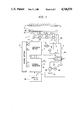
- FIG. 1 is a block diagram showing piping systems and electrical systems of a clamping device and a clamping confirming system according to this invention.
- FIG. 2 is a block diagram showing an arithmetic section in FIG. 1.
- FIG. 3 is a timing chart illustrating the operation of the clamping confirming device.
- This invention has been developed for a fluid-driven clamping device 1.
- the clamping device 1 comprises, for instance, a plurality of hydraulic cylinders 3 employed as clamping actuator means.
- the hydraulic cylinders 3 are operated through pressurized fluid 2, to tightly hold a variety of workpieces 6a, 6b and 6c between piston rods 4 and a reference piece 5 provided at the machining station.
- the fluid 2 is stored in a tank 7a, and is supplied to the hydraulic cylinders 3 through a supply pipe path 8a, a pressurized fluid source, namely, a pump 9a driven by a motor 9b, and an electromagnetic change-over valve 10.
- the fluid 2 thus supplied is returned to a tank 7b through a return pipe path 8b and the change-over valve 10.
- a clamping confirming device 11 comprises: a sensor section 12; an arithmetic section 13; an external sequencer 14; and a control section 37.
- the sensor section 12 is provided in the pipe path 8a, and consists of a rotary flow detector 15 and a pressure switch 16.
- the flow detector 15 operates to convert the flow rate of the pressurized fluid 2, for instance, into the speed (rpm) of a turbine, and to output a detection pulse S 1 proportional to the speed.
- the detection pulse S 1 is applied to the arithmetic section 13.
- the presure switch 16 detects the pressure which is required positively to clamp a workpiece to provide an electrical pressure signal S 2 .
- the electrical pressure signal S 2 is applied to the external sequencer 14.
- the external sequencer 14 operates to apply an instruction signal S 12 to an external device 39, such as a machining device or a transfer device, according to the following program.
- the control section 37 receiving an instruction signal S 10 , applies a gate change-over signal S 3 , a clear signal S 4 and a shift direction change-over signal S 5 to the arithmetic section 13.
- a pulse shaping circuit 17, a frequency divider 18, a gate 19 and an up-down counter 20 are connected to the flow detector 15 in the stated order, the up-down counter 20 is connected to a comparator 21, a display unit 22 and a digit driver 23, the output terminal of the comparator 21 is connected through a shift register 24, a memory 25 and, for instance, a photo-coupler type isolator 26 to the external sequencer 14, and the isolator 26 is connected to display lamps 32, 33, 34, 35 and 36.
- the frequency divider 18 operates to frequency-divide the detection pulse S 1 at a predetermined frequency division ratio according to a value which is set by a setting unit 38.
- a count signal S 6 of the counter 20 i.e. its count value
- values A, B, C, D and E set by digital switches 27, 28, 29, 30 and 31 which are driven by the digit driver 23, and whenever the count value coincides with any one of the set values, a coincidence signal S 7 is outputted.
- the signal S 7 is applied to the shift register 24 for shifting.
- the set values A, B and C provided by the digital switches 27, 28 and 29 are for the workpieces 6a, 6b and 6c, respectively.
- the set values D and E provided by the digital switches 30 and 31 are for over-clamping and unclamping, respectively.
- the control section 37 applies the gate change-over signal S 3 , the clear signal S 4 and the shift direction change-over signal S 5 respectively to the gate 19, the counter 20, and the shift register 24.
- the external sequencer 14 operates the control section 37, so that the clear signal S 4 is applied to the counter 20 to reset the latter, and the gate change-over signal S 3 is applied to the gate 19 to deliver the detection pulse S 1 to the "up" input terminal of the counter 20.
- the hydraulic cylinders 3 are held ready to receive the workpieces 6a, 6b and 6c with the piston rods 4 retracted.
- the external sequencer 14 detects the delivery of the workpiece 6c with a conventional means, such as a photo-electric sensor, to apply the change-over signal S 9 to the change-over valve 10 so that the pressurized fluid 2 is supplied into the first chambers of the hydraulic cylinders 3.
- a conventional means such as a photo-electric sensor
- the piston rods 4 of the hydraulic cylinders 3 are moved outwardly according to the amount of fluid thus supplied, thus cooperating with the reference piece 5 to hold the workpiece 6c therebetween.
- the fluid 2 in the second chambers of the hydraulic cylinders 3 is returned through the pipe path 8b into the tank 7b.
- the rotary flow detector 15 of the sensor section 12 provides the detection pulse S 1 which is proportional to the amount of fluid 2 supplied to the cylinders.
- the detection pulse S 1 is applied to the pulse shaping circuit 17 in the arithemtic section 13.
- the detection pulse S 1 is shaped by the pulse shaping circuit 17, and then frequency-divided at a predetermined frequency division ratio 1/n by the frequency divider 18.
- the output signal of the frequency divider 18 is applied to the gate 19.
- the counter 20 counts the detection pulse S 1 thus processed.
- the count value is applied, as a count signal S 6 , to the comparator 21, the display unit 22 and the digit driver 23.
- the display unit 22 is used to externally read the count value of the counter 20.
- the count value corresponds to the stroke of the hydraulic cylinders 3, and is displayed in such a manner that it can be directly read.
- the digit driver 23 supplies the outputs of the digital switches 27, 28, 29, 30 and 31 to one input terminal of the comparator 21 according to the count value.
- the count value of the counter 20 is compared with the set values A, B, C, D and E, and whenever it coincides with any one of the set values, a one-pulse coincidence signal S 7 is produced.
- the coincidence signal S 7 is supplied to the shift register 24.
- the shift register 24 provides its output signal S 8 in such a manner that the content is shifted in one direction during clamping and in the opposite derection during unclamping, by "H" level of the shift direction change-over signal S 5 .
- the output signal S 8 after being stored in the memory 25 just in case of power service interruption, is supplied through the isolator 26 to the external sequencer 14.
- the output signal S 8 is raised to "H" level in correspondence to the set values A, B and C, and the display lamps 32 through 36 are turned on, so that both accomplishment of the stroke of the hydraulic cylinders 3 and also the kinds of workpieces (6a, 6b and 6c) can be externally confirmed.
- the workpiece 6c is clamped. Therefore, after signals for workpieces 6a and 6b, which are larger than the workpiece 6c, have and 6b, which are larger than the workpiece 6c, have been outputted, the output signal S 8 is provided in response to an "H" level shift pulse for the workpiece 6c.
- the piston rods 4 of the hydraulic cylinders 3 are brought into contact with the workpiece 6c, the advance of the piston rods is stopped.
- the pressurized fluid 2 is still being supplied into the hydraulic cylinders 3 by the pump 9a and the motor 9b, and therefore the pressure of the fluid 2 is gradually increased.
- the pressure switch 16 detects the pressure and applies the pressure signal S 2 to the external sequencer 14.
- the external sequencer 14 the "H" level output signal S 8 for the workpiece 6c and the pressure signal S 2 from the pressure switch 16 and ANDed to confirm the correct clamping condition of the workpiece 6c to provide a confirmation signal. And the external sequencer 14 applies an appropriate instruction signal S 12 to the external device 39.
- an "H" level output signal S 8 is provided in correspondence to the set value D for overclamping, to confirm the absence of the workpiece.
- the workpiece 6c thus clamped is machined as required.
- the external sequencer 14 applies an instruction signal S 10 to the control section 37 to change the levels of the gate change-over signal S 3 and the shift direction change-over signal S 5 .
- the counter 20 is caused to perform a down-counting operation, and the direction of shift in the shift register 24 is inverted.
- the change-over valve 10 is operated to supply the pressurized fluid 2 into the second chambers of the hydraulic cylinders 3 to retract the piston rods 4. In this operation, the fluid 2 supplied into the hydraulic cylinders during clamping is returned to the tank 7b through the sensor section 12.
- the shift register 24 successively provides the output signals S 8 corresponding to the set values D, C, B, A and E.
- the external sequencer 14 confirms the unclamping of the workpiece, thus becoming ready for the following control.
- the frequency division ratio (1/n) of the frequency divider 18 should also be changed to a suitable value so as to maintain the sensor section 12 and the arithmetic section 13 operable in all cases.
- the hydraulic cylinders 3 are employed as actuators; however, they may be replaced, for instance, by hydraulic motors.
- the display unit 22, the memory 25 and the isolator 26 in the arithmetic section 13 may be eliminated as the case may be.
- Clamping, unclamping and overclamping positions for workpieces different in size from one another can be preset as desired by switching operations. Furthermore, the accomplishment of clamping of different workpieces can be confirmed without using limit switches and dogs on the actuators, and the confirming means can be installed at a place suitable for adjustment.
- the arithmetic section provides output signals separately according to the outputs of the actuators, the kinds of workpieces (workpiece clamping dimensions) can be detected from the output signals of the arithmetic section. Therefore, even if workpieces different in size are delivered to the machining station at random, the workpieces can be automatically sorted out, so that the following operation can be started immediately.
- the sensor section includes the pressure switch, and the arithmetic section comprises the frequency divider and the up-down counter, and the following effects are provided:
- the frequency divider can set the detected-pulse frequency division ratio to a suitable value
- the flow detector can be replaced by another one which is different therefrom in the number of pulses generated per unitary flow rate, when necessary. Furthermore, error due to temperature change or piping deflection can be corrected by adjusting the frequency division ratio. In addition, as the content of the counter is reset every detection, the integration of errors therein is prevented.
- the set values are provided for the kinds of workpieces, the overclamping position and the unclamping position, respectively. Therefore, the absence of the workpiece and the unclamping state can be electrically confirmed. Receiving these data, the arithmetic section and the external sequencer control the succeeding operations according to the machining program.
Landscapes
- Engineering & Computer Science (AREA)
- Human Computer Interaction (AREA)
- Manufacturing & Machinery (AREA)
- Physics & Mathematics (AREA)
- General Physics & Mathematics (AREA)
- Automation & Control Theory (AREA)
- Jigs For Machine Tools (AREA)
- Machine Tool Sensing Apparatuses (AREA)
Abstract
Description
Claims (5)
Applications Claiming Priority (2)
| Application Number | Priority Date | Filing Date | Title |
|---|---|---|---|
| JP60081894A JPS61241039A (en) | 1985-04-16 | 1985-04-16 | Confirming device for clamp |
| JP60-81894 | 1985-04-16 |
Publications (1)
| Publication Number | Publication Date |
|---|---|
| US4748570A true US4748570A (en) | 1988-05-31 |
Family
ID=13759146
Family Applications (1)
| Application Number | Title | Priority Date | Filing Date |
|---|---|---|---|
| US06/852,690 Expired - Lifetime US4748570A (en) | 1985-04-16 | 1986-04-15 | Clamping confirming device |
Country Status (2)
| Country | Link |
|---|---|
| US (1) | US4748570A (en) |
| JP (1) | JPS61241039A (en) |
Cited By (17)
| Publication number | Priority date | Publication date | Assignee | Title |
|---|---|---|---|---|
| US5031106A (en) * | 1988-06-30 | 1991-07-09 | Brother Kogyo Kabushiki Kaisha | Machine tool |
| US5051923A (en) * | 1988-08-08 | 1991-09-24 | Ricoh Company, Ltd. | Knowledge inferential processing apparatus |
| US5119310A (en) * | 1988-05-17 | 1992-06-02 | Amada Company, Limited | Device for measurement of workpiece dimensions and conforming automatic adjustment of bandsaw blade guide |
| US5208760A (en) * | 1988-05-17 | 1993-05-04 | Amada Company, Limited | Method and device for recognizing cross sectional external form and dimensions of a workpiece in a bandsaw machine |
| US5335955A (en) * | 1990-07-11 | 1994-08-09 | Kolari Pekka | Method and system for setting the hydraulic pressure influencing a grab member |
| US5587536A (en) * | 1995-08-17 | 1996-12-24 | Rasmussen; John | Differential pressure sensing device for pneumatic cylinders |
| US5825655A (en) * | 1994-08-02 | 1998-10-20 | Komatsu Ltd. | Normal operating condition restoration device |
| US5984617A (en) * | 1998-05-11 | 1999-11-16 | Cascade Corporation | Clamp for handling stacked loads of different sizes at different maximum clamping forces |
| US20050063811A1 (en) * | 2003-09-24 | 2005-03-24 | Seaberg Richard D. | Hydraulically-synchronized clamp for handling stacked loads different sizes |
| US20050146252A1 (en) * | 2003-12-30 | 2005-07-07 | Ksp Technologies Corp. | Cylinder apparatus with a capability of detecting piston position in a cylinder |
| US20060104781A1 (en) * | 2004-10-19 | 2006-05-18 | Auramo Oy | Method and apparatus for handling a load |
| US20060248960A1 (en) * | 2005-05-05 | 2006-11-09 | Liskow Karl J | Gripper gage assembly |
| US20110088795A1 (en) * | 2009-10-16 | 2011-04-21 | Hill Engineering Limited | Control system for a hydraulic coupler |
| US20110091267A1 (en) * | 2009-10-16 | 2011-04-21 | Ian Hill | Coupler |
| US9469965B2 (en) | 2009-09-22 | 2016-10-18 | Ian Hill | Hydraulic coupler with pin retention system for coupling an attachment to a work machine |
| CN106826299A (en) * | 2017-04-10 | 2017-06-13 | 江南大学 | Abrasive water-jet is thrown and bores milling one clamping device |
| CN109751966A (en) * | 2019-01-29 | 2019-05-14 | 广东联城住工装备信息科技有限公司 | The detection method of hydraulic clamping system, equipment of vibrating and hydraulic clamping system |
Families Citing this family (2)
| Publication number | Priority date | Publication date | Assignee | Title |
|---|---|---|---|---|
| US4820611A (en) * | 1987-04-24 | 1989-04-11 | Advanced Micro Devices, Inc. | Titanium nitride as an antireflection coating on highly reflective layers for photolithography |
| CN114670042B (en) * | 2022-04-08 | 2023-06-09 | 无锡贝斯特精机股份有限公司 | Intelligent clamp and control system |
Citations (11)
| Publication number | Priority date | Publication date | Assignee | Title |
|---|---|---|---|---|
| US3414136A (en) * | 1966-01-18 | 1968-12-03 | North American Rockwell | Underwater manipulator system |
| US3967242A (en) * | 1973-06-15 | 1976-06-29 | Hitachi, Ltd. | Automatic working machine |
| US4273505A (en) * | 1978-09-22 | 1981-06-16 | The United States Of America As Represented By The Administrator Of The National Aeronautics And Space Administration | Pneumatic inflatable end effector |
| US4484443A (en) * | 1980-10-20 | 1984-11-27 | Sumitomo Metal Industries, Ltd. | Control system for superhigh pressure generation circuit |
| US4530636A (en) * | 1980-10-08 | 1985-07-23 | Fujitsu Fanuc Limited | Device for operating a hand of an industrial robot |
| US4537547A (en) * | 1981-10-23 | 1985-08-27 | The United Kingdom Atomic Energy Authority | Manipulator |
| US4587618A (en) * | 1982-04-12 | 1986-05-06 | Kabushiki Kaisha Sankyo Seiki Seisakusho | Apparatus for controlling operation of an industrial robot |
| US4600985A (en) * | 1982-06-01 | 1986-07-15 | Fanuc Ltd. | Numerical control method and apparatus therefor |
| US4610597A (en) * | 1983-10-06 | 1986-09-09 | Intelledex Incorporated | Gripper interface for a robot |
| US4628499A (en) * | 1984-06-01 | 1986-12-09 | Scientific-Atlanta, Inc. | Linear servoactuator with integrated transformer position sensor |
| US4646225A (en) * | 1983-03-04 | 1987-02-24 | Fanuc Ltd | Adaptive feed rate controller for tracer head |
Family Cites Families (1)
| Publication number | Priority date | Publication date | Assignee | Title |
|---|---|---|---|---|
| JP2799225B2 (en) * | 1990-06-11 | 1998-09-17 | 株式会社神戸製鋼所 | Descaling method of titanium plate |
-
1985
- 1985-04-16 JP JP60081894A patent/JPS61241039A/en active Pending
-
1986
- 1986-04-15 US US06/852,690 patent/US4748570A/en not_active Expired - Lifetime
Patent Citations (11)
| Publication number | Priority date | Publication date | Assignee | Title |
|---|---|---|---|---|
| US3414136A (en) * | 1966-01-18 | 1968-12-03 | North American Rockwell | Underwater manipulator system |
| US3967242A (en) * | 1973-06-15 | 1976-06-29 | Hitachi, Ltd. | Automatic working machine |
| US4273505A (en) * | 1978-09-22 | 1981-06-16 | The United States Of America As Represented By The Administrator Of The National Aeronautics And Space Administration | Pneumatic inflatable end effector |
| US4530636A (en) * | 1980-10-08 | 1985-07-23 | Fujitsu Fanuc Limited | Device for operating a hand of an industrial robot |
| US4484443A (en) * | 1980-10-20 | 1984-11-27 | Sumitomo Metal Industries, Ltd. | Control system for superhigh pressure generation circuit |
| US4537547A (en) * | 1981-10-23 | 1985-08-27 | The United Kingdom Atomic Energy Authority | Manipulator |
| US4587618A (en) * | 1982-04-12 | 1986-05-06 | Kabushiki Kaisha Sankyo Seiki Seisakusho | Apparatus for controlling operation of an industrial robot |
| US4600985A (en) * | 1982-06-01 | 1986-07-15 | Fanuc Ltd. | Numerical control method and apparatus therefor |
| US4646225A (en) * | 1983-03-04 | 1987-02-24 | Fanuc Ltd | Adaptive feed rate controller for tracer head |
| US4610597A (en) * | 1983-10-06 | 1986-09-09 | Intelledex Incorporated | Gripper interface for a robot |
| US4628499A (en) * | 1984-06-01 | 1986-12-09 | Scientific-Atlanta, Inc. | Linear servoactuator with integrated transformer position sensor |
Cited By (22)
| Publication number | Priority date | Publication date | Assignee | Title |
|---|---|---|---|---|
| US5119310A (en) * | 1988-05-17 | 1992-06-02 | Amada Company, Limited | Device for measurement of workpiece dimensions and conforming automatic adjustment of bandsaw blade guide |
| US5208760A (en) * | 1988-05-17 | 1993-05-04 | Amada Company, Limited | Method and device for recognizing cross sectional external form and dimensions of a workpiece in a bandsaw machine |
| US5031106A (en) * | 1988-06-30 | 1991-07-09 | Brother Kogyo Kabushiki Kaisha | Machine tool |
| US5051923A (en) * | 1988-08-08 | 1991-09-24 | Ricoh Company, Ltd. | Knowledge inferential processing apparatus |
| US5335955A (en) * | 1990-07-11 | 1994-08-09 | Kolari Pekka | Method and system for setting the hydraulic pressure influencing a grab member |
| US5825655A (en) * | 1994-08-02 | 1998-10-20 | Komatsu Ltd. | Normal operating condition restoration device |
| US5587536A (en) * | 1995-08-17 | 1996-12-24 | Rasmussen; John | Differential pressure sensing device for pneumatic cylinders |
| US5984617A (en) * | 1998-05-11 | 1999-11-16 | Cascade Corporation | Clamp for handling stacked loads of different sizes at different maximum clamping forces |
| US7056078B2 (en) | 2003-09-24 | 2006-06-06 | Cascade Corporation | Hydraulically-synchronized clamp for handling stacked loads different sizes |
| US20050063811A1 (en) * | 2003-09-24 | 2005-03-24 | Seaberg Richard D. | Hydraulically-synchronized clamp for handling stacked loads different sizes |
| US20050146252A1 (en) * | 2003-12-30 | 2005-07-07 | Ksp Technologies Corp. | Cylinder apparatus with a capability of detecting piston position in a cylinder |
| US20060104781A1 (en) * | 2004-10-19 | 2006-05-18 | Auramo Oy | Method and apparatus for handling a load |
| US20060248960A1 (en) * | 2005-05-05 | 2006-11-09 | Liskow Karl J | Gripper gage assembly |
| US7694583B2 (en) | 2005-05-05 | 2010-04-13 | Control Gaging, Inc. | Gripper gage assembly |
| US9469965B2 (en) | 2009-09-22 | 2016-10-18 | Ian Hill | Hydraulic coupler with pin retention system for coupling an attachment to a work machine |
| US20110088795A1 (en) * | 2009-10-16 | 2011-04-21 | Hill Engineering Limited | Control system for a hydraulic coupler |
| US20110091267A1 (en) * | 2009-10-16 | 2011-04-21 | Ian Hill | Coupler |
| US8863640B2 (en) * | 2009-10-16 | 2014-10-21 | Hill Engineering Limited | Control system for a hydraulic coupler |
| US9297141B2 (en) | 2009-10-16 | 2016-03-29 | Ian Hill | Coupler |
| CN106826299A (en) * | 2017-04-10 | 2017-06-13 | 江南大学 | Abrasive water-jet is thrown and bores milling one clamping device |
| CN106826299B (en) * | 2017-04-10 | 2022-09-27 | 江南大学 | Abrasive water jet is thrown and is bored and mill integrative clamping jig |
| CN109751966A (en) * | 2019-01-29 | 2019-05-14 | 广东联城住工装备信息科技有限公司 | The detection method of hydraulic clamping system, equipment of vibrating and hydraulic clamping system |
Also Published As
| Publication number | Publication date |
|---|---|
| JPS61241039A (en) | 1986-10-27 |
Similar Documents
| Publication | Publication Date | Title |
|---|---|---|
| US4748570A (en) | Clamping confirming device | |
| EP0199823B1 (en) | Monitoring device for an injection molding machine | |
| US4673173A (en) | Workpiece clamping device | |
| US4743823A (en) | Method and device for correcting backlash | |
| EP0270688B1 (en) | Method and apparatus for automatically adjusting the origin of an injection molding machine | |
| US5239479A (en) | Process for determining the presence or the dimensions or the correct positioning of a workpiece on a machine tool | |
| EP0218340B1 (en) | Method and apparatus for electric discharge machining | |
| US4499359A (en) | Shape compensating method for wire-out electric discharge machining | |
| US4766700A (en) | Method and apparatus for determining the position of a workpiece in an NC-controlled machine | |
| EP0034927A2 (en) | Spindle orientation control apparatus | |
| GB2256167A (en) | Automatic adjustment of bandsaw blade guides and determination of workpiece shape and dimensions. | |
| SU745377A3 (en) | Control device for cyclic feeding of multisectional fuel pump sets | |
| US5208760A (en) | Method and device for recognizing cross sectional external form and dimensions of a workpiece in a bandsaw machine | |
| US4829717A (en) | Method and relevant apparatus for controlling the machining of mechanical pieces | |
| JPH0435279B2 (en) | ||
| EP0245522B1 (en) | Metering device for injection molding machine | |
| JPH0445293B2 (en) | ||
| JPS6126963Y2 (en) | ||
| US5981898A (en) | Method of controlling electrode pressure application force in an electric gun | |
| EP0533998A1 (en) | Bending machine | |
| KR850000311B1 (en) | Spindle orientation control apparatus | |
| US3700993A (en) | Apparatus for controlling relative motion between gage jaws on a contacting gage | |
| JPH11212618A (en) | Work machining method for nc lathe | |
| KR100190574B1 (en) | V-shape groove coordinate and right angle measuring jig for drum base | |
| SU1001016A1 (en) | Device for in-process checking of diameters of parts being machined on npc machinc-tools |
Legal Events
| Date | Code | Title | Description |
|---|---|---|---|
| AS | Assignment |
Owner name: KABUSHIKI KAISHA NIPPEI TOYAMA, WORLD TRADE CENTER Free format text: ASSIGNMENT OF ASSIGNORS INTEREST.;ASSIGNORS:SHOCHI, TOSHIYUKI;NAKAJIMA, KENEI;JOBOJI, NOBUAKI;REEL/FRAME:004831/0244 Effective date: 19860408 Owner name: KABUSHIKI KAISHA NIPPEI TOYAMA, WORLD TRADE CENTER Free format text: ASSIGNMENT OF ASSIGNORS INTEREST;ASSIGNORS:SHOCHI, TOSHIYUKI;NAKAJIMA, KENEI;JOBOJI, NOBUAKI;REEL/FRAME:004831/0244 Effective date: 19860408 |
|
| STCF | Information on status: patent grant |
Free format text: PATENTED CASE |
|
| FEPP | Fee payment procedure |
Free format text: PAYOR NUMBER ASSIGNED (ORIGINAL EVENT CODE: ASPN); ENTITY STATUS OF PATENT OWNER: LARGE ENTITY |
|
| FPAY | Fee payment |
Year of fee payment: 4 |
|
| FEPP | Fee payment procedure |
Free format text: PAYOR NUMBER ASSIGNED (ORIGINAL EVENT CODE: ASPN); ENTITY STATUS OF PATENT OWNER: LARGE ENTITY Free format text: PAYER NUMBER DE-ASSIGNED (ORIGINAL EVENT CODE: RMPN); ENTITY STATUS OF PATENT OWNER: LARGE ENTITY |
|
| FPAY | Fee payment |
Year of fee payment: 8 |
|
| FPAY | Fee payment |
Year of fee payment: 12 |