US4754819A - Method for improving cuttings transport during the rotary drilling of a wellbore - Google Patents
Method for improving cuttings transport during the rotary drilling of a wellbore Download PDFInfo
- Publication number
- US4754819A US4754819A US07/024,442 US2444287A US4754819A US 4754819 A US4754819 A US 4754819A US 2444287 A US2444287 A US 2444287A US 4754819 A US4754819 A US 4754819A
- Authority
- US
- United States
- Prior art keywords
- wellbore
- drill
- drill string
- annulus
- drilling
- Prior art date
- Legal status (The legal status is an assumption and is not a legal conclusion. Google has not performed a legal analysis and makes no representation as to the accuracy of the status listed.)
- Expired - Fee Related
Links
- 238000005553 drilling Methods 0.000 title claims abstract description 44
- 238000005520 cutting process Methods 0.000 title claims description 28
- 238000000034 method Methods 0.000 title claims description 6
- 239000003638 chemical reducing agent Substances 0.000 claims abstract description 22
- 239000012530 fluid Substances 0.000 claims abstract description 17
- 238000005086 pumping Methods 0.000 claims abstract description 6
- 239000003381 stabilizer Substances 0.000 description 15
- 230000015572 biosynthetic process Effects 0.000 description 5
- 238000005755 formation reaction Methods 0.000 description 5
- 238000003756 stirring Methods 0.000 description 5
- 239000007787 solid Substances 0.000 description 3
- 238000004140 cleaning Methods 0.000 description 2
- 239000002131 composite material Substances 0.000 description 2
- 239000002245 particle Substances 0.000 description 2
- 241001427367 Gardena Species 0.000 description 1
- 238000009825 accumulation Methods 0.000 description 1
- 230000004075 alteration Effects 0.000 description 1
- 230000015556 catabolic process Effects 0.000 description 1
- 239000004568 cement Substances 0.000 description 1
- 239000012141 concentrate Substances 0.000 description 1
- 238000001816 cooling Methods 0.000 description 1
- 230000000694 effects Effects 0.000 description 1
- 238000005516 engineering process Methods 0.000 description 1
- 239000003623 enhancer Substances 0.000 description 1
- 230000002706 hydrostatic effect Effects 0.000 description 1
- 230000001771 impaired effect Effects 0.000 description 1
- 238000010348 incorporation Methods 0.000 description 1
- 238000012423 maintenance Methods 0.000 description 1
- 239000000463 material Substances 0.000 description 1
- 238000012986 modification Methods 0.000 description 1
- 230000004048 modification Effects 0.000 description 1
- 230000035515 penetration Effects 0.000 description 1
- 239000011148 porous material Substances 0.000 description 1
- 230000001737 promoting effect Effects 0.000 description 1
- 238000000518 rheometry Methods 0.000 description 1
- 238000007789 sealing Methods 0.000 description 1
Images


Classifications
-
- E—FIXED CONSTRUCTIONS
- E21—EARTH DRILLING; MINING
- E21B—EARTH DRILLING, e.g. DEEP DRILLING; OBTAINING OIL, GAS, WATER, SOLUBLE OR MELTABLE MATERIALS OR A SLURRY OF MINERALS FROM WELLS
- E21B7/00—Special methods or apparatus for drilling
- E21B7/04—Directional drilling
-
- E—FIXED CONSTRUCTIONS
- E21—EARTH DRILLING; MINING
- E21B—EARTH DRILLING, e.g. DEEP DRILLING; OBTAINING OIL, GAS, WATER, SOLUBLE OR MELTABLE MATERIALS OR A SLURRY OF MINERALS FROM WELLS
- E21B17/00—Drilling rods or pipes; Flexible drill strings; Kellies; Drill collars; Sucker rods; Cables; Casings; Tubings
- E21B17/10—Wear protectors; Centralising devices, e.g. stabilisers
-
- E—FIXED CONSTRUCTIONS
- E21—EARTH DRILLING; MINING
- E21B—EARTH DRILLING, e.g. DEEP DRILLING; OBTAINING OIL, GAS, WATER, SOLUBLE OR MELTABLE MATERIALS OR A SLURRY OF MINERALS FROM WELLS
- E21B21/00—Methods or apparatus for flushing boreholes, e.g. by use of exhaust air from motor
Definitions
- a drill bit In the drilling of wells into the earth by rotary drilling techniques, a drill bit is attached to a drill string, lowered into a well, and rotated in contact with the earth; thereby breaking and fracturing the earth and forming a wellbore thereinto.
- a drilling fluid is circulated down the drill string and through nozzles provided in the drill bit to the bottom of the wellbore and thence upward through the annular space formed between the drill string and the wall of the wellbore.
- the drilling fluid serves many purposes including cooling the bit, supplying hydrostatic pressure upon the formations penetrated by the wellbore to prevent fluids existing under pressure therein from flowing into the wellbore, reducing torque and drag between the drill string and the wellbore, maintaining the stability of open hole (uncased) intervals, and sealing pores and openings penetrated by the bit.
- a most important function is hole cleaning (carrying capacity), i.e. the removal of drill solids (cuttings) beneath the bit, and the transport of this material to the surface through the wellbore annulus.
- Hole cleaning can also be a problem under conditions where the drill string is in tension and intervals of negative eccentricity result as the drill string is pulled to the high side of the annulus. In the latter situation, the drill string is not usually in direct contact with the cuttings bed, but the latter's presence can lead to incidents of stuck pipe when circulation is stopped to pull out of the hole.
- U.S. Pat. No. 4,361,193 to Gravley teaches the incorporation of one or more fluid nozzles in the drill string for directing a portion of the drilling fluid circulating in the drill string outwardly into the annulus of the wellbore about the drill string so as to effect a stirring action on the drill cuttings and improve their removal by the return flow of the drilling fluid.
- the present invention is directed to a method and system for increasing the cuttings transport efficiency during the rotary drilling of a wellbore.
- a drill string is formed of a plurality of sections of drill pipe interconnected at tool joints with a drill bit at its lower end.
- a drilling fluid is circulated down the drill and up the annulus between the wellbore and the drill string. As the drilling fluid is circulated, it flows through a plurality of annulus reducers located at spaced-apart positions along the drill string. The annulus reducers impart a cyclical pumping action to the flowing drilling fluid.
- the drill string is axially reciprocated. An extension capability of the drill string maintains continuous weight on the drill bit during this reciprocating action.
- the annulus reducers provide for at least two differing sizes of annulus restrictions alternately spaced along the wellbore.
- the reciprocating movement of the drill string is such that each annulus reducer is moved a distance at least equal to the axial spacing of the annulus reducers along the drill string.
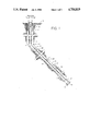
- FIG. 1 illustrates a drill string lying along the lower side of a deviated wellbore extending into the earth.
- FIG. 2 illustrates a cuttings bed buildup around the drill string of FIG. 1 during rotary drilling operations.
- FIG. 3 illustrates the drill string of the present invention for use in the deviated wellbore of FIG. 1 to minimize a cuttings bed buildup.
- FIGS. 4-6 illustrate alternate embodiments for the annulus reducers utilized with the drill string of FIG. 3.
- FIG. 1 there is illustrated a conventional drill string used in the rotary drilling of a wellbore, particularly a deviated wellbore.
- a deviated wellbore 1 has a vertical first portion 3 which extends from the surface 5 of the earth to a kick-off point 7 and a deviated second portion 9 of the wellbore which extends from the kick-off point 7 to the wellbore bottom 11.
- the illustrated embodiment shows a wellbore having a first vertical section extending to a kick-off point
- the teachings of the present invention are applicable to other types of wellbores as well. For instance, under certain types of drilling conditions involving porous formations and large pressure differentials, the teachings herein may be applicable to vertical wellbores. Also some deviated wellbores need not have the first vertical section illustrated in FIG. 1.
- a shallow or surface casing string 13 is shown in the wellbore surrounded by a cement sheath 15.
- a drill string 17, having a drill bit 19 at the lower end thereof, is positioned in the wellbore 1.
- the drill string 17 is comprised of drill pipe 21 and the drill bit 19, and will normally include at least one drill collar 23.
- the drill pipe 21 is comprised of joints of pipe that are interconnected together by tool joints 25, and the drill string may also include wear knots for their normal function.
- the drill string In the deviated second portion 9, the drill string normally rests on the lower side 27 of the wellbore.
- Drill cuttings are removed from the wellbore bottom 11 by circulating drilling fluid, as shown by the arrows.
- a normal drilling mud circulation rate is about 100 feet/minute average velocity in the annulus between a 5 inch drill pipe and a nominal 121/4 inch wellbore. This velocity is frequently inadequate to remove the drill cuttings.
- problems are experienced at the greater flow rate. Pump pressures increase dramatically causing added expenditure of power and maintenance. The wellbore may not be able to support this increased pressure without breakdown of the formation and subsequent loss of drilling mud circulation.
- any decrease in the size of the annulus will cause both a pressure and velocity increase in the drilling mud flow.
- the mud flow velocity of 100 feet/minute around the 5 inch drill pipe will increase to about 115 feet/minute about a 63/8 inch tool joint and to about 145 feet/minute about an 8 inch drill collar.
- the mud flow velocity would be about 123 feet/minute about the 5 inch drill pipe, 145 feet/minute about the 63/8 inch tool joint and 198 feet/minute about the 8 inch drill collar.
- the present invention provides for the imparting of a cyclical pumping action into the drilling mud flow up the wellbore annulus.
- This pumping action provides a stirring of the cuttings which enhances their transport up the wellbore by the flowing drilling mud.
- FIGS. 2 and 3 Referring first to FIG. 2, it can be seen that in a deviated wellbore 30 each drill cutting particle 31 will tend to fall (as shown by arrow 32) from the flow of drilling mud up the wellbore (as shown by arrow 33). These particles accumulate on the lower side of the wellbore to form a cuttings bed as shown at 34 beneath and around the drill pipe 35 which also rests along the lower side of the wellbore on the tool joints 36.
- FIG. 3 there is diagrammatically shown the drilling tool of the present invention, the use of which provides a stirring action to the drill cuttings to keep them from falling out of the mud flow stream.
- the drill bit 41 At the lower end of the drill pipe 40 is the drill bit 41 and a conventional bottom hole assembly (BHA) 42 including the drill motor 53 and the measuring while drilling system 54. Adjacent the bottom hole assembly 42 is shown the extension sub 43 which provides the immediate source of weight on the drill bit.
- the drill pipe 40 may be cyclically moved up and down in the wellbore, to the extent allowed by the extension sub, without taking weight off the drill bit.
- Located at spaced-apart positions along the drill pipe 40 are a plurality of annulus reducers 44.
- FIG. 4 illustrates an annulus reducer 44 that is a drill pipe diameter enhancer wherein the mud flow cross-sectional area is reduced to the area 45 within wellbore 50.
- FIG. 5 illustrates an annulus reducer 46 that is a wellbore diameter reducer wherein the mud flow cross-sectional area is reduced to the area 47 within the wellbore 50.
- FIG. 6 illustrates an annulus reducer 48 that is a conventional drill pipe stabilizer wherein the mud flow cross-sectional area is reduced to the area 49 within the wellbore 50.
- the drill tool of FIG. 3 is used to provide the desired stirring action to the drill cuttings in the following manner.
- the drill pipe is cyclically moved up and down in the wellbore a distance d as permitted by the extension sub 43 which continuously maintains weight on the drill bit to advance the drilling operations.
- the annulus reducers 44 are also moved up and down the same distance d. It is preferable that the spacing between these annulus reducers be no greater than the distance d so that the up or down position of any one of such reducers overlaps with the down or up position respectively of an adjacent reducer. In this configuration, each axial movement of the drill pipe up and down in the wellbore cyclically causes the adjacent moving reduced annuli to overlap.
- drill bit 41 is a 121/4 inch bit.
- Drill motor 53 is 73/4 inch Delta 1000 mud motor supplied by Dyna-Drill Co. of Irvine, Calif., and which is 241/2 feet in length.
- the measuring-while-drilling system 54 can be of the types supplied by the Anadrill/Schlumberger of Houston, Tex.; Gearhart Industries of Fort Worth, Tex.; Teleco Oil Field Services of Meriden, Conn.; or Exploration Logging of Sacramento, Calif., for example.
- Other suitable measuring-while-drilling systems are disclosed in U.S. Pat. Nos. 3,309,656, 3,739,331; 3,770,006; and 3,789,355.
- the spiral-bladed stabilizers 56 can be of the integral blade or non-magnetic integral blade type supplied by Norton Christensen, Inc. of Houston, Tex. or of the rig-replaceable sleeve type supplied by Drilco (Div. of Smith International) of Houston, Tex., for example.
- annulus area reducers are supplied by Servco, Division of Smith International, Inc., Gardena, Calif., such as the sleeve-type stabilizer or the integral blade stabilizer.
- annulus area reducers are available in the form of drill collar stabilizers, drill pipe stabilizers, integral blade stabilizers, sleeve stabilizers and spiral blade stabilizers. Numerous manufacturers supply such stabilizers as also listed in the Composite Catalog of Oil Field Equipment and Services, 36th Revision, 1984-85, published by World Oil, Houston, Texas. All of these stabilizers come in varying sizes for differing wellbore sizes. Such stabilizers include the clamp-on type stabilizer of Servco, a Division of Smith International, Inc., and the clamp-on and interchangeable sleeve stabilizers of SMF International, Paris, France as examples.
Abstract
A wellbore drill string is formed of a plurality of sections of drill pipe interconnected at tool joints with a drill bit at its lower end. A drilling fluid is circulated down the drill string and up the annulus between the wellbore and the drill string. A plurality of annulus reducers located at spaced-apart positions along the drill string impart a cyclical pumping action to the flowing drilling fluid. During drilling, the drill string is axially reciprocated and an extension capability to the drill string maintains continuous weight on the drill bit.
Description
In the drilling of wells into the earth by rotary drilling techniques, a drill bit is attached to a drill string, lowered into a well, and rotated in contact with the earth; thereby breaking and fracturing the earth and forming a wellbore thereinto. A drilling fluid is circulated down the drill string and through nozzles provided in the drill bit to the bottom of the wellbore and thence upward through the annular space formed between the drill string and the wall of the wellbore. The drilling fluid serves many purposes including cooling the bit, supplying hydrostatic pressure upon the formations penetrated by the wellbore to prevent fluids existing under pressure therein from flowing into the wellbore, reducing torque and drag between the drill string and the wellbore, maintaining the stability of open hole (uncased) intervals, and sealing pores and openings penetrated by the bit. A most important function is hole cleaning (carrying capacity), i.e. the removal of drill solids (cuttings) beneath the bit, and the transport of this material to the surface through the wellbore annulus.
Reduced bit life, slow penetration rate, bottom hole fill up during trips, stuck pipe, and lost circulation, can result when drill solids are inefficiently removed in the drilling of vertical boreholes. The efficiency of cuttings removal and transport becomes even more critical in drilling the deviated or inclined wellbore, particularly when the inclination is greater than 60 degrees, because as cuttings settle along the lower side of the wellbore, this accumulation results in the formation of a cutting bed. As a result of the reduction in net area open to flow, cuttings transport becomes severely impaired. If the drill pipe lies on the low side of an open hole interval (positive eccentricity), drill solids concentrate in the constricted space and conditions susceptible to differential sticking of the pipe can also occur. Hole cleaning can also be a problem under conditions where the drill string is in tension and intervals of negative eccentricity result as the drill string is pulled to the high side of the annulus. In the latter situation, the drill string is not usually in direct contact with the cuttings bed, but the latter's presence can lead to incidents of stuck pipe when circulation is stopped to pull out of the hole.
Various methods have been proposed for improving the efficiency of cuttings removal from the wellbore, including, promoting the formation of a particular flow regime throughout the annulus, altering the rheology of the entire drilling fluid volume, increasing the annular velocity, rotating pipe, and combinations thereof. In the case of the inclined wellbore, U.S. Pat. No, 4,246,975 to Dellinger, teaches the use of eccentric tool joints to stir up the cuttings bed, thus aiding cuttings removal.
U.S. Pat. No. 4,361,193 to Gravley teaches the incorporation of one or more fluid nozzles in the drill string for directing a portion of the drilling fluid circulating in the drill string outwardly into the annulus of the wellbore about the drill string so as to effect a stirring action on the drill cuttings and improve their removal by the return flow of the drilling fluid.
The present invention is directed to a method and system for increasing the cuttings transport efficiency during the rotary drilling of a wellbore. A drill string is formed of a plurality of sections of drill pipe interconnected at tool joints with a drill bit at its lower end. A drilling fluid is circulated down the drill and up the annulus between the wellbore and the drill string. As the drilling fluid is circulated, it flows through a plurality of annulus reducers located at spaced-apart positions along the drill string. The annulus reducers impart a cyclical pumping action to the flowing drilling fluid. During drilling, the drill string is axially reciprocated. An extension capability of the drill string maintains continuous weight on the drill bit during this reciprocating action.
In a further aspect, the annulus reducers provide for at least two differing sizes of annulus restrictions alternately spaced along the wellbore.
In a still further aspect, the reciprocating movement of the drill string is such that each annulus reducer is moved a distance at least equal to the axial spacing of the annulus reducers along the drill string.
FIG. 1 illustrates a drill string lying along the lower side of a deviated wellbore extending into the earth.
FIG. 2 illustrates a cuttings bed buildup around the drill string of FIG. 1 during rotary drilling operations.
FIG. 3 illustrates the drill string of the present invention for use in the deviated wellbore of FIG. 1 to minimize a cuttings bed buildup.
FIGS. 4-6 illustrate alternate embodiments for the annulus reducers utilized with the drill string of FIG. 3.
Referring to FIG. 1 there is illustrated a conventional drill string used in the rotary drilling of a wellbore, particularly a deviated wellbore. A deviated wellbore 1 has a vertical first portion 3 which extends from the surface 5 of the earth to a kick-off point 7 and a deviated second portion 9 of the wellbore which extends from the kick-off point 7 to the wellbore bottom 11. Although the illustrated embodiment shows a wellbore having a first vertical section extending to a kick-off point, the teachings of the present invention are applicable to other types of wellbores as well. For instance, under certain types of drilling conditions involving porous formations and large pressure differentials, the teachings herein may be applicable to vertical wellbores. Also some deviated wellbores need not have the first vertical section illustrated in FIG. 1.
A shallow or surface casing string 13 is shown in the wellbore surrounded by a cement sheath 15. A drill string 17, having a drill bit 19 at the lower end thereof, is positioned in the wellbore 1. The drill string 17 is comprised of drill pipe 21 and the drill bit 19, and will normally include at least one drill collar 23. The drill pipe 21 is comprised of joints of pipe that are interconnected together by tool joints 25, and the drill string may also include wear knots for their normal function. In the deviated second portion 9, the drill string normally rests on the lower side 27 of the wellbore.
Drill cuttings are removed from the wellbore bottom 11 by circulating drilling fluid, as shown by the arrows.
It is a common occurrence in the drilling of high-angle boreholes, as shown in FIG. 1, to have difficulty in removing the drill cuttings from the wellbore. A normal drilling mud circulation rate is about 100 feet/minute average velocity in the annulus between a 5 inch drill pipe and a nominal 121/4 inch wellbore. This velocity is frequently inadequate to remove the drill cuttings. By increasing the mud flow velocity to 150 feet/minute, cuttings removal has been found to be enhanced. However, problems are experienced at the greater flow rate. Pump pressures increase dramatically causing added expenditure of power and maintenance. The wellbore may not be able to support this increased pressure without breakdown of the formation and subsequent loss of drilling mud circulation.
Also, any decrease in the size of the annulus will cause both a pressure and velocity increase in the drilling mud flow. For example, the mud flow velocity of 100 feet/minute around the 5 inch drill pipe will increase to about 115 feet/minute about a 63/8 inch tool joint and to about 145 feet/minute about an 8 inch drill collar. In addition, if the 121/4 inch wellbore were reduced to 111/4 inch, the mud flow velocity would be about 123 feet/minute about the 5 inch drill pipe, 145 feet/minute about the 63/8 inch tool joint and 198 feet/minute about the 8 inch drill collar. These velocity changes are even more pronounced in drilling a 97/8 inch wellbore with 5-inch drill pipe.
To overcome such problems of drill cuttings removal in wellbore drilling operations, particularly in deviated wellbores, the present invention provides for the imparting of a cyclical pumping action into the drilling mud flow up the wellbore annulus. This pumping action provides a stirring of the cuttings which enhances their transport up the wellbore by the flowing drilling mud. This may be better understood by reference to FIGS. 2 and 3. Referring first to FIG. 2, it can be seen that in a deviated wellbore 30 each drill cutting particle 31 will tend to fall (as shown by arrow 32) from the flow of drilling mud up the wellbore (as shown by arrow 33). These particles accumulate on the lower side of the wellbore to form a cuttings bed as shown at 34 beneath and around the drill pipe 35 which also rests along the lower side of the wellbore on the tool joints 36.
Referring now to FIG. 3 there is diagrammatically shown the drilling tool of the present invention, the use of which provides a stirring action to the drill cuttings to keep them from falling out of the mud flow stream. At the lower end of the drill pipe 40 is the drill bit 41 and a conventional bottom hole assembly (BHA) 42 including the drill motor 53 and the measuring while drilling system 54. Adjacent the bottom hole assembly 42 is shown the extension sub 43 which provides the immediate source of weight on the drill bit. The drill pipe 40 may be cyclically moved up and down in the wellbore, to the extent allowed by the extension sub, without taking weight off the drill bit. Located at spaced-apart positions along the drill pipe 40 are a plurality of annulus reducers 44. These annulus reducers may be all of the same type or may be of different types at select spaced-apart positions along the drill pipe. FIG. 4 illustrates an annulus reducer 44 that is a drill pipe diameter enhancer wherein the mud flow cross-sectional area is reduced to the area 45 within wellbore 50. FIG. 5 illustrates an annulus reducer 46 that is a wellbore diameter reducer wherein the mud flow cross-sectional area is reduced to the area 47 within the wellbore 50. FIG. 6 illustrates an annulus reducer 48 that is a conventional drill pipe stabilizer wherein the mud flow cross-sectional area is reduced to the area 49 within the wellbore 50.
The drill tool of FIG. 3 is used to provide the desired stirring action to the drill cuttings in the following manner. During drilling operations, the drill pipe is cyclically moved up and down in the wellbore a distance d as permitted by the extension sub 43 which continuously maintains weight on the drill bit to advance the drilling operations. As the drill pipe is moved up and down the distance d, the annulus reducers 44 are also moved up and down the same distance d. It is preferable that the spacing between these annulus reducers be no greater than the distance d so that the up or down position of any one of such reducers overlaps with the down or up position respectively of an adjacent reducer. In this configuration, each axial movement of the drill pipe up and down in the wellbore cyclically causes the adjacent moving reduced annuli to overlap. The greater mud flow velocity through these moving reduced annuli imparts cyclical pumping action to the cuttings along the wellbore where the reduced annuli are located, thereby resulting in an enhanced transportion of the drill cuttings from the wellbore to the surface of the earth. Each of these stabilizers are supplied for varying wellbore size.
In one example, drill bit 41 is a 121/4 inch bit. Drill motor 53 is 73/4 inch Delta 1000 mud motor supplied by Dyna-Drill Co. of Irvine, Calif., and which is 241/2 feet in length. The measuring-while-drilling system 54 can be of the types supplied by the Anadrill/Schlumberger of Houston, Tex.; Gearhart Industries of Fort Worth, Tex.; Teleco Oil Field Services of Meriden, Conn.; or Exploration Logging of Sacramento, Calif., for example. Other suitable measuring-while-drilling systems are disclosed in U.S. Pat. Nos. 3,309,656, 3,739,331; 3,770,006; and 3,789,355. The spiral-bladed stabilizers 56 can be of the integral blade or non-magnetic integral blade type supplied by Norton Christensen, Inc. of Houston, Tex. or of the rig-replaceable sleeve type supplied by Drilco (Div. of Smith International) of Houston, Tex., for example.
Several alternative embodiments are available for configuration of the extension sub 43. When powered by hydraulic pressure, the teaching of U.S. Pat. No, 3,105,561 to Kellner for a hydraulic actuated drill collar may be utilized. The technology utilized in conventional bumper subs or jars for drilling and fishing operations may also be used. Numerous manufacturers supply such bumper subs or jars as listed in the Composite Catalog of Oil Field Equipment and Services, 36th Revision, 1984-85, published by World Oil, Houston, Texas. Such bumper subs include the lubricated bumper sub No. 746-23 of Baker Service Tools, the A-Z fishing bumper sub of A-Z International Tool Co., and the fishing bumper sub of Bowen and the ball bearing drive bumper jar of Driltrol as examples.
Several such annulus area reducers are supplied by Servco, Division of Smith International, Inc., Gardena, Calif., such as the sleeve-type stabilizer or the integral blade stabilizer.
Several types of annulus area reducers are available in the form of drill collar stabilizers, drill pipe stabilizers, integral blade stabilizers, sleeve stabilizers and spiral blade stabilizers. Numerous manufacturers supply such stabilizers as also listed in the Composite Catalog of Oil Field Equipment and Services, 36th Revision, 1984-85, published by World Oil, Houston, Texas. All of these stabilizers come in varying sizes for differing wellbore sizes. Such stabilizers include the clamp-on type stabilizer of Servco, a Division of Smith International, Inc., and the clamp-on and interchangeable sleeve stabilizers of SMF International, Paris, France as examples.
While a preferred embodiment of the invention has been described and illustrated, numerous modifications or alterations may be made without departing from the spirit and scope of the invention as set forth in the appended claims.
Claims (2)
1. A method for increasing the cuttings transport efficiency during the rotary drilling of a wellbore with a drill string formed of a plurality of sections of drill pipe interconnected at tool joints and having a drill bit at the lower end thereof, comprising:
(a) circulating a drilling fluid down the drill string and returning said fluid from the wellbore up the annulus formed between the drill string and the wellbore wall,
(b) flowing said drilling fluid through a plurality of annulus reducers successively varying in diameter and located at spaced apart positions along said drill string and
(c) axially reciprocating said drill string a distance at least equal to the axial spacing of said variable diameter annulus reducers along said drill string during drilling while continuously maintaining drilling bit weight so as to provide a cyclical pumping action to the flow of drilling fluids in the axial direction of the wellbore which enhances the transport of drill cuttings up the annulus of the wellbore.
2. The method of claim 1 wherein the step of axially reciprocating said drill string is carried out such that positions of adjacent variable diameter annulus reducers at least overlap during each of said reciprocating movements.
Priority Applications (1)
| Application Number | Priority Date | Filing Date | Title |
|---|---|---|---|
| US07/024,442 US4754819A (en) | 1987-03-11 | 1987-03-11 | Method for improving cuttings transport during the rotary drilling of a wellbore |
Applications Claiming Priority (1)
| Application Number | Priority Date | Filing Date | Title |
|---|---|---|---|
| US07/024,442 US4754819A (en) | 1987-03-11 | 1987-03-11 | Method for improving cuttings transport during the rotary drilling of a wellbore |
Publications (1)
| Publication Number | Publication Date |
|---|---|
| US4754819A true US4754819A (en) | 1988-07-05 |
Family
ID=21820614
Family Applications (1)
| Application Number | Title | Priority Date | Filing Date |
|---|---|---|---|
| US07/024,442 Expired - Fee Related US4754819A (en) | 1987-03-11 | 1987-03-11 | Method for improving cuttings transport during the rotary drilling of a wellbore |
Country Status (1)
| Country | Link |
|---|---|
| US (1) | US4754819A (en) |
Cited By (26)
| Publication number | Priority date | Publication date | Assignee | Title |
|---|---|---|---|---|
| US5316091A (en) * | 1993-03-17 | 1994-05-31 | Exxon Production Research Company | Method for reducing occurrences of stuck drill pipe |
| US5435402A (en) * | 1994-09-28 | 1995-07-25 | Ziegenfuss; Mark | Self-propelled earth drilling hammer-bit assembly |
| WO1998038411A2 (en) * | 1997-02-28 | 1998-09-03 | Ocre (Scotland) Limited | Apparatus for use in drilling operations |
| US6425448B1 (en) | 2001-01-30 | 2002-07-30 | Cdx Gas, L.L.P. | Method and system for accessing subterranean zones from a limited surface area |
| US6439320B2 (en) | 1998-11-20 | 2002-08-27 | Cdx Gas, Llc | Wellbore pattern for uniform access to subterranean deposits |
| US6598686B1 (en) | 1998-11-20 | 2003-07-29 | Cdx Gas, Llc | Method and system for enhanced access to a subterranean zone |
| US6662870B1 (en) | 2001-01-30 | 2003-12-16 | Cdx Gas, L.L.C. | Method and system for accessing subterranean deposits from a limited surface area |
| US6679322B1 (en) | 1998-11-20 | 2004-01-20 | Cdx Gas, Llc | Method and system for accessing subterranean deposits from the surface |
| US6681855B2 (en) | 2001-10-19 | 2004-01-27 | Cdx Gas, L.L.C. | Method and system for management of by-products from subterranean zones |
| US6708764B2 (en) | 2002-07-12 | 2004-03-23 | Cdx Gas, L.L.C. | Undulating well bore |
| US6725922B2 (en) | 2002-07-12 | 2004-04-27 | Cdx Gas, Llc | Ramping well bores |
| US20080060571A1 (en) * | 1998-11-20 | 2008-03-13 | Cdx Gas, Llc. | Method and system for accessing subterranean deposits from the surface and tools therefor |
| US20090194337A1 (en) * | 2008-02-01 | 2009-08-06 | Aquatic Company | Spiral Ribbed Aluminum Drillpipe |
| US7703549B2 (en) | 2005-05-02 | 2010-04-27 | Schlumberger Technology Corporation | Method and apparatus for removing cuttings in high-angle wells |
| US8333245B2 (en) | 2002-09-17 | 2012-12-18 | Vitruvian Exploration, Llc | Accelerated production of gas from a subterranean zone |
| US8376039B2 (en) | 1998-11-20 | 2013-02-19 | Vitruvian Exploration, Llc | Method and system for accessing subterranean deposits from the surface and tools therefor |
| US8376052B2 (en) | 1998-11-20 | 2013-02-19 | Vitruvian Exploration, Llc | Method and system for surface production of gas from a subterranean zone |
| US8434568B2 (en) | 1998-11-20 | 2013-05-07 | Vitruvian Exploration, Llc | Method and system for circulating fluid in a well system |
| US8528219B2 (en) | 2009-08-17 | 2013-09-10 | Magnum Drilling Services, Inc. | Inclination measurement devices and methods of use |
| US9611700B2 (en) | 2014-02-11 | 2017-04-04 | Saudi Arabian Oil Company | Downhole self-isolating wellbore drilling systems |
| US10260295B2 (en) | 2017-05-26 | 2019-04-16 | Saudi Arabian Oil Company | Mitigating drilling circulation loss |
| US11131144B1 (en) | 2020-04-02 | 2021-09-28 | Saudi Arabian Oil Company | Rotary dynamic system for downhole assemblies |
| CN113802983A (en) * | 2021-09-18 | 2021-12-17 | 洲际海峡能源科技有限公司 | Method for removing horizontal well debris bed |
| US11306555B2 (en) | 2020-04-02 | 2022-04-19 | Saudi Arabian Oil Company | Drill pipe with dissolvable layer |
| US11319777B2 (en) | 2020-04-02 | 2022-05-03 | Saudi Arabian Oil Company | Extended surface system with helical reamers |
| US20230241653A1 (en) * | 2022-01-31 | 2023-08-03 | Saudi Arabian Oil Company | Hybrid descaling tool and methods |
Citations (8)
| Publication number | Priority date | Publication date | Assignee | Title |
|---|---|---|---|---|
| US4246975A (en) * | 1979-04-04 | 1981-01-27 | Mobil Oil Corporation | Wellbore drilling technique using eccentric tool joints to mitigate pressure-differential sticking |
| US4361193A (en) * | 1980-11-28 | 1982-11-30 | Mobil Oil Corporation | Method and arrangement for improving cuttings removal and reducing differential pressure sticking of drill strings in wellbores |
| US4368787A (en) * | 1980-12-01 | 1983-01-18 | Mobil Oil Corporation | Arrangement for removing borehole cuttings by reverse circulation with a downhole bit-powered pump |
| US4373592A (en) * | 1980-11-28 | 1983-02-15 | Mobil Oil Corporation | Rotary drilling drill string stabilizer-cuttings grinder |
| US4428441A (en) * | 1979-04-04 | 1984-01-31 | Mobil Oil Corporation | Method and apparatus for reducing the differential pressure sticking tendency of a drill string |
| US4552230A (en) * | 1984-04-10 | 1985-11-12 | Anderson Edwin A | Drill string shock absorber |
| EP0184304A1 (en) * | 1984-11-07 | 1986-06-11 | Mobil Oil Corporation | Method and system of drilling deviated wellbores |
| US4646855A (en) * | 1984-11-06 | 1987-03-03 | Mobil Oil Corporation | Method for raising and lowering a drill string in a wellbore during drilling operations |
-
1987
- 1987-03-11 US US07/024,442 patent/US4754819A/en not_active Expired - Fee Related
Patent Citations (8)
| Publication number | Priority date | Publication date | Assignee | Title |
|---|---|---|---|---|
| US4246975A (en) * | 1979-04-04 | 1981-01-27 | Mobil Oil Corporation | Wellbore drilling technique using eccentric tool joints to mitigate pressure-differential sticking |
| US4428441A (en) * | 1979-04-04 | 1984-01-31 | Mobil Oil Corporation | Method and apparatus for reducing the differential pressure sticking tendency of a drill string |
| US4361193A (en) * | 1980-11-28 | 1982-11-30 | Mobil Oil Corporation | Method and arrangement for improving cuttings removal and reducing differential pressure sticking of drill strings in wellbores |
| US4373592A (en) * | 1980-11-28 | 1983-02-15 | Mobil Oil Corporation | Rotary drilling drill string stabilizer-cuttings grinder |
| US4368787A (en) * | 1980-12-01 | 1983-01-18 | Mobil Oil Corporation | Arrangement for removing borehole cuttings by reverse circulation with a downhole bit-powered pump |
| US4552230A (en) * | 1984-04-10 | 1985-11-12 | Anderson Edwin A | Drill string shock absorber |
| US4646855A (en) * | 1984-11-06 | 1987-03-03 | Mobil Oil Corporation | Method for raising and lowering a drill string in a wellbore during drilling operations |
| EP0184304A1 (en) * | 1984-11-07 | 1986-06-11 | Mobil Oil Corporation | Method and system of drilling deviated wellbores |
Cited By (54)
| Publication number | Priority date | Publication date | Assignee | Title |
|---|---|---|---|---|
| US5316091A (en) * | 1993-03-17 | 1994-05-31 | Exxon Production Research Company | Method for reducing occurrences of stuck drill pipe |
| US5435402A (en) * | 1994-09-28 | 1995-07-25 | Ziegenfuss; Mark | Self-propelled earth drilling hammer-bit assembly |
| WO1998038411A2 (en) * | 1997-02-28 | 1998-09-03 | Ocre (Scotland) Limited | Apparatus for use in drilling operations |
| WO1998038411A3 (en) * | 1997-02-28 | 1999-02-18 | Ocre Scotland Ltd | Apparatus for use in drilling operations |
| GB2338738A (en) * | 1997-02-28 | 1999-12-29 | Ocre | Apparatus for use in drilling operations |
| US8297377B2 (en) | 1998-11-20 | 2012-10-30 | Vitruvian Exploration, Llc | Method and system for accessing subterranean deposits from the surface and tools therefor |
| US8297350B2 (en) | 1998-11-20 | 2012-10-30 | Vitruvian Exploration, Llc | Method and system for accessing subterranean deposits from the surface |
| US6478085B2 (en) | 1998-11-20 | 2002-11-12 | Cdx Gas, Llp | System for accessing subterranean deposits from the surface |
| US6561288B2 (en) | 1998-11-20 | 2003-05-13 | Cdx Gas, Llc | Method and system for accessing subterranean deposits from the surface |
| US6575235B2 (en) | 1998-11-20 | 2003-06-10 | Cdx Gas, Llc | Subterranean drainage pattern |
| US6598686B1 (en) | 1998-11-20 | 2003-07-29 | Cdx Gas, Llc | Method and system for enhanced access to a subterranean zone |
| US8371399B2 (en) | 1998-11-20 | 2013-02-12 | Vitruvian Exploration, Llc | Method and system for accessing subterranean deposits from the surface and tools therefor |
| US8464784B2 (en) | 1998-11-20 | 2013-06-18 | Vitruvian Exploration, Llc | Method and system for accessing subterranean deposits from the surface and tools therefor |
| US6668918B2 (en) | 1998-11-20 | 2003-12-30 | Cdx Gas, L.L.C. | Method and system for accessing subterranean deposit from the surface |
| US6679322B1 (en) | 1998-11-20 | 2004-01-20 | Cdx Gas, Llc | Method and system for accessing subterranean deposits from the surface |
| US8434568B2 (en) | 1998-11-20 | 2013-05-07 | Vitruvian Exploration, Llc | Method and system for circulating fluid in a well system |
| US8376039B2 (en) | 1998-11-20 | 2013-02-19 | Vitruvian Exploration, Llc | Method and system for accessing subterranean deposits from the surface and tools therefor |
| US9551209B2 (en) | 1998-11-20 | 2017-01-24 | Effective Exploration, LLC | System and method for accessing subterranean deposits |
| US6439320B2 (en) | 1998-11-20 | 2002-08-27 | Cdx Gas, Llc | Wellbore pattern for uniform access to subterranean deposits |
| US6732792B2 (en) | 1998-11-20 | 2004-05-11 | Cdx Gas, Llc | Multi-well structure for accessing subterranean deposits |
| US8376052B2 (en) | 1998-11-20 | 2013-02-19 | Vitruvian Exploration, Llc | Method and system for surface production of gas from a subterranean zone |
| US20080060571A1 (en) * | 1998-11-20 | 2008-03-13 | Cdx Gas, Llc. | Method and system for accessing subterranean deposits from the surface and tools therefor |
| US8813840B2 (en) | 1998-11-20 | 2014-08-26 | Efective Exploration, LLC | Method and system for accessing subterranean deposits from the surface and tools therefor |
| US8511372B2 (en) | 1998-11-20 | 2013-08-20 | Vitruvian Exploration, Llc | Method and system for accessing subterranean deposits from the surface |
| US8505620B2 (en) | 1998-11-20 | 2013-08-13 | Vitruvian Exploration, Llc | Method and system for accessing subterranean deposits from the surface and tools therefor |
| US8479812B2 (en) | 1998-11-20 | 2013-07-09 | Vitruvian Exploration, Llc | Method and system for accessing subterranean deposits from the surface and tools therefor |
| US6688388B2 (en) | 1998-11-20 | 2004-02-10 | Cdx Gas, Llc | Method for accessing subterranean deposits from the surface |
| US8469119B2 (en) | 1998-11-20 | 2013-06-25 | Vitruvian Exploration, Llc | Method and system for accessing subterranean deposits from the surface and tools therefor |
| US8316966B2 (en) | 1998-11-20 | 2012-11-27 | Vitruvian Exploration, Llc | Method and system for accessing subterranean deposits from the surface and tools therefor |
| US8291974B2 (en) | 1998-11-20 | 2012-10-23 | Vitruvian Exploration, Llc | Method and system for accessing subterranean deposits from the surface and tools therefor |
| US6604580B2 (en) | 1998-11-20 | 2003-08-12 | Cdx Gas, Llc | Method and system for accessing subterranean zones from a limited surface area |
| US6425448B1 (en) | 2001-01-30 | 2002-07-30 | Cdx Gas, L.L.P. | Method and system for accessing subterranean zones from a limited surface area |
| US7036584B2 (en) | 2001-01-30 | 2006-05-02 | Cdx Gas, L.L.C. | Method and system for accessing a subterranean zone from a limited surface area |
| US6662870B1 (en) | 2001-01-30 | 2003-12-16 | Cdx Gas, L.L.C. | Method and system for accessing subterranean deposits from a limited surface area |
| US6681855B2 (en) | 2001-10-19 | 2004-01-27 | Cdx Gas, L.L.C. | Method and system for management of by-products from subterranean zones |
| US6725922B2 (en) | 2002-07-12 | 2004-04-27 | Cdx Gas, Llc | Ramping well bores |
| US6708764B2 (en) | 2002-07-12 | 2004-03-23 | Cdx Gas, L.L.C. | Undulating well bore |
| US8333245B2 (en) | 2002-09-17 | 2012-12-18 | Vitruvian Exploration, Llc | Accelerated production of gas from a subterranean zone |
| US7703549B2 (en) | 2005-05-02 | 2010-04-27 | Schlumberger Technology Corporation | Method and apparatus for removing cuttings in high-angle wells |
| US7814996B2 (en) | 2008-02-01 | 2010-10-19 | Aquatic Company | Spiral ribbed aluminum drillpipe |
| US20090194337A1 (en) * | 2008-02-01 | 2009-08-06 | Aquatic Company | Spiral Ribbed Aluminum Drillpipe |
| US8528219B2 (en) | 2009-08-17 | 2013-09-10 | Magnum Drilling Services, Inc. | Inclination measurement devices and methods of use |
| US10156100B2 (en) | 2014-02-11 | 2018-12-18 | Saudi Arabian Oil Company | Downhole self-isolating wellbore drilling systems |
| US10138686B2 (en) | 2014-02-11 | 2018-11-27 | Saudi Arabian Oil Company | Downhole self-isolating wellbore drilling systems |
| US9611700B2 (en) | 2014-02-11 | 2017-04-04 | Saudi Arabian Oil Company | Downhole self-isolating wellbore drilling systems |
| US10161192B2 (en) | 2014-02-11 | 2018-12-25 | Saudi Arabian Oil Company | Downhole self-isolating wellbore drilling systems |
| US10260295B2 (en) | 2017-05-26 | 2019-04-16 | Saudi Arabian Oil Company | Mitigating drilling circulation loss |
| US11448021B2 (en) | 2017-05-26 | 2022-09-20 | Saudi Arabian Oil Company | Mitigating drilling circulation loss |
| US11131144B1 (en) | 2020-04-02 | 2021-09-28 | Saudi Arabian Oil Company | Rotary dynamic system for downhole assemblies |
| US11306555B2 (en) | 2020-04-02 | 2022-04-19 | Saudi Arabian Oil Company | Drill pipe with dissolvable layer |
| US11319777B2 (en) | 2020-04-02 | 2022-05-03 | Saudi Arabian Oil Company | Extended surface system with helical reamers |
| CN113802983A (en) * | 2021-09-18 | 2021-12-17 | 洲际海峡能源科技有限公司 | Method for removing horizontal well debris bed |
| US20230241653A1 (en) * | 2022-01-31 | 2023-08-03 | Saudi Arabian Oil Company | Hybrid descaling tool and methods |
| US11897011B2 (en) * | 2022-01-31 | 2024-02-13 | Saudi Arabian Oil Company | Hybrid descaling tool and methods |
Similar Documents
| Publication | Publication Date | Title |
|---|---|---|
| US4754819A (en) | Method for improving cuttings transport during the rotary drilling of a wellbore | |
| US5447200A (en) | Method and apparatus for downhole sand clean-out operations in the petroleum industry | |
| US4844182A (en) | Method for improving drill cuttings transport from a wellbore | |
| KR100411580B1 (en) | Method and appartatus for drilling with high-pressure, reduced solid content liquid | |
| US4373592A (en) | Rotary drilling drill string stabilizer-cuttings grinder | |
| US6837313B2 (en) | Apparatus and method to reduce fluid pressure in a wellbore | |
| US5040620A (en) | Methods and apparatus for drilling subterranean wells | |
| CA1167832A (en) | Reduction of the frictional coefficient in a borehole by the use of vibration | |
| US4368787A (en) | Arrangement for removing borehole cuttings by reverse circulation with a downhole bit-powered pump | |
| US4428441A (en) | Method and apparatus for reducing the differential pressure sticking tendency of a drill string | |
| US7481280B2 (en) | Method and apparatus for conducting earth borehole operations using coiled casing | |
| US6446737B1 (en) | Apparatus and method for rotating a portion of a drill string | |
| US5150757A (en) | Methods and apparatus for drilling subterranean wells | |
| US5839520A (en) | Method of drilling well bores | |
| US10519734B2 (en) | Downhole milling tool apparatus | |
| US6138777A (en) | Hydraulic underreamer and sections for use therein | |
| CN106062299A (en) | Multi fluid drilling system | |
| CN1056553A (en) | Be used to the method and apparatus drilling and take a sample | |
| US20020157871A1 (en) | Apparatus and method of oscillating a drill string | |
| US8074717B2 (en) | Drilling method and downhole cleaning tool | |
| CN106030022B (en) | Dual cycle fluid hammer drilling system | |
| US6223839B1 (en) | Hydraulic underreamer and sections for use therein | |
| US2336029A (en) | Well drilling apparatus | |
| RU2190089C1 (en) | Process of deep perforation of cased wells | |
| CA2487182C (en) | Hydraulic underreamer and sections for use therein |
Legal Events
| Date | Code | Title | Description |
|---|---|---|---|
| AS | Assignment |
Owner name: MOBIL OIL CORPORATION, A CORP. OF NY Free format text: ASSIGNMENT OF ASSIGNORS INTEREST.;ASSIGNOR:DELLINGER, THOMAS B.;REEL/FRAME:004693/0617 Effective date: 19870304 |
|
| REMI | Maintenance fee reminder mailed | ||
| LAPS | Lapse for failure to pay maintenance fees | ||
| FP | Lapsed due to failure to pay maintenance fee |
Effective date: 19920705 |
|
| STCH | Information on status: patent discontinuation |
Free format text: PATENT EXPIRED DUE TO NONPAYMENT OF MAINTENANCE FEES UNDER 37 CFR 1.362 |