US4780883A - Data modem with adaptive synchronized speed change - Google Patents
Data modem with adaptive synchronized speed change Download PDFInfo
- Publication number
- US4780883A US4780883A US06/878,765 US87876586A US4780883A US 4780883 A US4780883 A US 4780883A US 87876586 A US87876586 A US 87876586A US 4780883 A US4780883 A US 4780883A
- Authority
- US
- United States
- Prior art keywords
- modem
- speed
- secs
- transmission
- transmitting
- Prior art date
- Legal status (The legal status is an assumption and is not a legal conclusion. Google has not performed a legal analysis and makes no representation as to the accuracy of the status listed.)
- Expired - Fee Related
Links
Images


Classifications
-
- H—ELECTRICITY
- H04—ELECTRIC COMMUNICATION TECHNIQUE
- H04L—TRANSMISSION OF DIGITAL INFORMATION, e.g. TELEGRAPHIC COMMUNICATION
- H04L1/00—Arrangements for detecting or preventing errors in the information received
- H04L1/20—Arrangements for detecting or preventing errors in the information received using signal quality detector
-
- H—ELECTRICITY
- H04—ELECTRIC COMMUNICATION TECHNIQUE
- H04L—TRANSMISSION OF DIGITAL INFORMATION, e.g. TELEGRAPHIC COMMUNICATION
- H04L1/00—Arrangements for detecting or preventing errors in the information received
- H04L1/0001—Systems modifying transmission characteristics according to link quality, e.g. power backoff
- H04L1/0015—Systems modifying transmission characteristics according to link quality, e.g. power backoff characterised by the adaptation strategy
-
- H—ELECTRICITY
- H04—ELECTRIC COMMUNICATION TECHNIQUE
- H04L—TRANSMISSION OF DIGITAL INFORMATION, e.g. TELEGRAPHIC COMMUNICATION
- H04L1/00—Arrangements for detecting or preventing errors in the information received
- H04L1/0001—Systems modifying transmission characteristics according to link quality, e.g. power backoff
- H04L1/0023—Systems modifying transmission characteristics according to link quality, e.g. power backoff characterised by the signalling
- H04L1/0025—Transmission of mode-switching indication
-
- H—ELECTRICITY
- H04—ELECTRIC COMMUNICATION TECHNIQUE
- H04L—TRANSMISSION OF DIGITAL INFORMATION, e.g. TELEGRAPHIC COMMUNICATION
- H04L1/00—Arrangements for detecting or preventing errors in the information received
- H04L1/004—Arrangements for detecting or preventing errors in the information received by using forward error control
- H04L1/0045—Arrangements at the receiver end
- H04L1/0054—Maximum-likelihood or sequential decoding, e.g. Viterbi, Fano, ZJ algorithms
-
- H—ELECTRICITY
- H04—ELECTRIC COMMUNICATION TECHNIQUE
- H04L—TRANSMISSION OF DIGITAL INFORMATION, e.g. TELEGRAPHIC COMMUNICATION
- H04L1/00—Arrangements for detecting or preventing errors in the information received
- H04L1/12—Arrangements for detecting or preventing errors in the information received by using return channel
- H04L1/16—Arrangements for detecting or preventing errors in the information received by using return channel in which the return channel carries supervisory signals, e.g. repetition request signals
Definitions
- This invention relates generally to the field of modems suitable for data communications at varying data transmission rates. More particularly, this invention relates to a data modem which adaptively adjusts its transmission rate in accordance with line quality to optimize data throughput over changing transmission lines.
- U.S. Pat. No. 4,4387,511 to Baran discloses a high speed modem suitable for dialup telephone lines in which the telephone pass-band is subdivided into 64 sub bands each with its own carrier. Each carrier is individually amplitude and phase modulated in order to transmit at a relatively low data rate on each carrier. The net result is a relatively high data rate. Baran's modem determines during a training period which portions of the telephone line spectrum may be most effectively utilized to carry data. Those carriers which are most impaired, are dropped in order to reduce the effective data rate while maximizing data throughput for a given set of channel impairments.
- Baran modem is not currently compatible with existing network control and diagnostic systems such as the Racal-Milgo® CMS series of network control and diagnostic equipment. Also, Baran's modem is only able to measure line conditions during its initial training period. Any line improvements occurring after that training period will not be recognized or accounted for, thus possibly reducing effective utilization of Bandwidth.
- Another problem with such modems is a less than optimal speed change protocol which can result in two modems temporarily winding up at different speeds which cause disruption of user data until a reinitialization occurs. This results primarily when one modem which is assigned absolute control over speed increases at any given time blindly assumes that it upspeed command correctly reaches its counterpart. An upspeed command which is not properly received due to, for example, phase hits on the line can cause such situations. It is also possible that power failures, brown outs and the like can cause neither modem to retain control over increases in speed so that a pair of modems is locked at a speed which is lower than the optimum transmission rate.
- the Codex® model 2660 modem uses an interruptive inband signaling as part of its speed change protocol. No secondary channel signaling is used. While this modem has a mechanism for switching its master/slave relationship similar to the present invention, the protocol for speed changes is less than optimal in that it allows one modem to demand upspeed without consulting the other. This can result in two modems operating at different speeds if the command to change speeds is damaged in transmission. It also has less immunity to confusion over master/slave identity or transmission speed in the event of brownout or damage to control signals in transmission.
- the present invention alleviates many of these problems as well as providing a protocol with minimal user data interruption as well as minimizing secondary channel interruption while providing a high degree of reliability in speed change signaling.
- a method for changing the data transmission rates in a synchronous data communication system including a first modem and a second modem coupled together through a transmission channel, the transmission channel including a first path for transmission from the first modem to the second modem and a second path for transmission from the second modem to the first modem, includes the steps of determining, at the first modem, that the second path of the transmission channel is adequately high in quality to support an increase in transmission rate. Next it is determined, at the second modem, that the first path of the transmission channel is adequately high in quality to support an increase in transmission rate. A training sequence is then transmitted at an increased transmission rate from the second modem to the first modem.
- a training sequence is transmitted at the increased transmission rate from the first modem to the second modem.
- the determining steps are carried out by comparing the average minimum cost function of a Viterbi decoder with a predetermined threshold and weighting transient phenomenon so that the line quality is measured predominantly on the basis of relatively long term averages.
- FIG. 1 is a functional block diagram of a pair of modems incorporating the present invention.
- FIG. 2, including FIG. 2A through FIG. 2F is a flow chart describing the operation of the present invention.
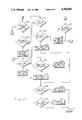
- FIG. 3 is a hardware block diagram of a modem of the present invention.
- a convolutional encoded modem utilizing Viterbi decoding forms the heart of the present data modem.
- Viterbi decoders are now well known and commonly used in the modem art to achieve maximum likelihood sequence estimation decoding of convolutionally coded data. Such decoders are described, for example, in Forney, "The Viterbi Algorithm", Proceedings of the IEEE, Vol. 61, No. 3, March 1973; Hayes, "The Viterbi Algorithm Applied to Digital Data Transmission” Journal of Communications Society, Vol. 13, pages 15-20, March 1975, U.S. Pat. Nos. 4,578,800 to Yasuda, et al.; and 4,562,426 to Forney, Jr. These documents are incorporated by reference as though disclosed fully herein.
- the modem of the present invention operates over four wire conditioned telephone lines such as 3002, +D-1, or CCITT M1020 lines.
- the present invention is especially useful for high speed data modems operated under such conditions at 12,000 BPS and above, but of course this is not to be limiting.
- the present modem is capable of operating at either 12,000, 14,400 or 16,800 BPS depending upon the quality of the transmission line.
- the present modem is preferably designed for compatibility with known network control and diagnostic systems such as those disclosed in U.S. Pat. No. 4,385,384 to Rosbury et al. This patent is incorporated by reference as though disclosed fully herein.
- TX channel is a secondary channel preferably utilizing low speed FSK modulation at 75 to 150 bits per second.
- User data is modulated over the communication channel utilizing convolutional coding with a 256 point constellation at 16.8 KBPS, a 128 point constellation at 14.4 KBPS and a 65 point constellation at 12 KBPS.
- Inband network control signals may also be utilized by preceding control signals such as those used to initiate speed changes with a training sequence or other suitable mechanism for encoding control signals into the user data stream.
- RacalMilgo® T1 inband signaling is utilized.
- T1 signaling is a form of signaling implemented as an unidirectional message transmission having the following format: [modem training sequence] [brief squelch] [127 symbols of carrier] [sync signal] [short (T1) signaling message at 2400 baud, one bit per symbol] [brief squelch] [modem training sequence] [user data]. While this form of inband signaling is preferred, it will be clear to those skilled in the art that many other forms of signaling may be used to serve an equivalent purpose. Thus, references to T1 signaling herein should be viewed only as illustrative.
- the present invention contemplates both upspeed and downspeed conversions (referred to hereinafter as fall forward or fallforward and fall back or fallback respectively). Further, the present invention contemplates utilization in systems with and without network controllers. In those systems without a network controller, remote modem control (RMC) may be utilized with secondary channel signaling as well as inband signaling to effect speed changes. In those systems having a network controller, the system utilizes a combination of T1 inband signaling and secondary channel signaling to effect speed changes.
- Remote Modem Control is a feature common in the art which allows a single modem, such as the Omnimode® series modem manufactured by Racal-Milgo®, to be used to control features characteristics and options of remote modems from its control panel.
- the modem's control panel acts as the network controller in a limited capacity.
- the secondary channel diagnostics and control functions are assumed to have high priority.
- this protocol is designed to disrupt secondary channel data as well as user data as little as possible.
- the speed change protocol is implemented with inband T1 signaling in a manner which is least disruptive of user data.
- a high level of acknowledgement is retained to assure that each modem remains aware of the other's condition at all times, thus largely eliminating disruptive reinitialization.
- the present invention finds greater utility in four wire leased line environments in which it is possible that one pair of wires may be capable of handling a higher speed of transmission than the other pair. There is of course no way to know which pair of wires will be likely to support the higher or lower transmission rates at any given time. It is therefore advantageous to provide a protocol which will enable the modem transmitting on the line with the greatest likelihood of having the lowest capacity to dominate in order to establish an orderly mechanism for such control. To achieve this, one modem is designated "master” and the other is designated “slave". The modem which is designated as the master modem will always initiate a fallforward speed change.
- communication begins at a speed which is established either from the control panel or from the modem's nonvolatile memory (that is, the most recent speed used by the modem). Speed increases will occur if possible until the highest tolerable rate is achieved. If any modem in the system is unable to reliably transmit over the channel, it can initiate a fallback to the next lower speed. If the modem is operating in the T1 environment the modem which last requested a fallback is designated master and is the only modem which may initiate an increase in speed. In this manner, the modem at all weakest link in the communication channel is generally assured of controlling the speed of the entire network. In the RMC or TX environment, the central site modem is always designated master.
- FIG. 1 a functional block diagram of a data communication system including the present invention is shown.
- the system of FIG. 1 represents a point-to-point data communication system including a modem 10 coupled through a communication channel 12 to a second modem 14.
- modems 10 and 14 include many other elements not shown but which are standard and well known in the modem art.
- Modem 10 includes a Viterbi decoder 16 which is used in the modem's receiver to decode the inband transmitted data.
- Viterbi decoder 16 produces a binary signal computed from a minimum cost function at its output 18.
- the signal at output 18 is referred to as "Cost SQ" (Signal Quality) herein.
- the cost as used herein means the magnitude of the euclidean distance between a received constellation point and the ideal constellation point).
- the cost function at output18 is obtained by summing the euclidean distance between the received signal point and the closest ideal point over a trellis path history of the previous N bauds. The average minimum cost is then obtained by integrating this minimum cost over a predetermined number of bauds.
- the output of the Viterbi decoder is a number that is processed by fallback and fallforward decision logics.
- the minimum cost information is provided to fallback decision logic 20 which includes a counter for counting the number of retrain attempts necessitated by data errors in the received data.
- the output 18 of Viterbi decoder 16 is also provided to a fall forward decision logic block 22 which processes the cost SQ signal at 18 to determine if a speed increase is possible.
- the output of fallback decision logic 20 is a fallback request signal which is transmitted to an auto speed state sequencer 24 the operation of which (along with fall back decision logic 20 and fall forward decision logic 22) is described by the flow chart of FIG. 2.
- the output of fall forward decision logic 22 can be viewed as a request for an increase in speed which is also provided to auto speed state sequencer 24.
- the output of 22 is provided in the form of a logic level. This logic level is obtained by comparing the average minimum cost from the Viterbi algorithm to a predetermined threshold. When the signal quality is high (therefore the average minimum cost is low) this comparison results in a logical 1 at the output of 22. When line quality degrades below the predetermined threshold, the logic level at the output of 22 drops to a logic 0.
- a logic level is obtained by comparing the average minimum cost from the Viterbi algorithm to a predetermined threshold. When the signal quality is high (therefore the average minimum cost is low) this comparison results in a logical 1 at the output of 22. When line quality degrades below the predetermined threshold, the logic level at the output of 22 drops to a logic 0.
- cost Sq is integrated in the fallforward decision logic 22 for approximately 8 minutes, 15 minutes, 1 hour or 2 hours depending on an integration time strap which is user selectable.
- the timer times are selected to be much shorter than a typical time period in which transmission line quality changes (frequently hours, days or even weeks). In this manner, transient phenomenon are given a small weight in determining overall transmission line quality. If the integration timer expired, then a fallforward flag is set and a request to fall forward sent from logic 22 to state sequencer 24.
- cost SQ While cost SQ is being integrated the modem receiver can be affected by line impairments (phase hits, amplitude hits, etc). If the effect of the impairments on the cost SQ is not significant, then the integration will continue with no interruption.
- Control panel 26 is also coupled to fall forward decision logic and fall back decision logic as well as an EIA RS 232 speed select logic block 28 so that control panel 26 may provide configuration information to each of these blocks. Such configuration information is utilized to inform the various parts of the modem exactly what soft strappable configuration the modem is currently in. Control panel 26 is also utilized to override automatic speed change information as desired by the user via its direct connection to the auto speed state sequencer 24.
- EIA RS-232 speed select logic block 28 serves to process the data rate signal from a DTE per circuit CH of a standard RS-232 interface. In the present invention this is accomplished by selecting the data rate which is soft strapped into the modem from the control panel in response to DTE speed change commands. Speed changes may also be initiated manually by a network controller 30.
- Speed change commands from the auto speed state sequencer 24 are encoded for transmission over the communication channel 12 by a command encoder 32 prior to transmission either by a T1 inband transmitter 34 or a TX FSK transmitter 36 depending upon whether inband signaling or secondary channel signaling is to be utilized for implementing the speed change.
- Such speed change commands received from modem 14 are received either by a T1 inband receiver 38 or a TX FSK receiver 40 prior to processing by a command decoder 42. When such commands are decoded by decoder 42 they are forwarded to auto speed state sequencer 24 for further processing.
- Modem 14 may be similarly configured to include a Viterbi decoder 116 having an output 118 coupled to a fallback decision logic block 120 and a fall forward decision logic block 122.
- Blocks 120 and 122 are coupled to a similar auto speed state sequencer 124.
- a control panel 126 is similarly coupled to blocks 120, 122, 124 and EIA speed select logic block 128.
- State sequencer 124 is coupled to a command encoder 132 which provides speed change commands to inband transmitter 134 and FSK transmitter 136.
- An inband receiver 138 and a FSK secondary channel receiver 140 feed incoming commands to command decoder 142 in a manner similar to that of modem 10.
- a handshaking protocol having two levels of acknowledgement is established.
- a master/slave relationship is created between modem 10 and modem 14.
- the modem which most recently required a speed decrease is established to be the master modem in the T1 environment.
- the central site modem is always master. Only the master moden may initiate speed increases. In this manner the modem which most recently had the poorest quality line always has control over increases in speed.
- two possible protocols for speed change may be utilized depending upon whether secondary channel is available for use (RMC or TX environment) or not (T1 environment).
- modem 10 has most recently requested a speed decrease (fallback) so that modem 10 is the master modem and modem 14 is the slave modem. If the line quality is measured by Viterbi decoder 16 of modem 10 is high enough so that modem 10 determines that it can support an increase in transmission speed, it transmits a request to increase speed to modem 14. In this situation where no network is transmitted via inband transmitter 34. If modem 14 is unable to support an increase in transmission rate, it acknowledges the request and responds that it is unable to support a speed increase. At this point, the master/slave modem identities are switched so that modem 14 now controls speed increases.
- modem 10 waits for 10 seconds to again attempt to increase speed. If a second attempt fails, modem 10 will restart its cost SQ integration timer.
- the master When the master receives a training sequence at the new speed it will return a training sequence at the new speed.
- the master will abort the handshake if it does not receive an acknowledgement from the slave within 10 seconds or if after it squelches carrier it does not receive a training sequence from the slave within 5 seconds.
- the slave will abort the handshake if it does not detect the squelch within 10 seconds of its transmission of an acknowledgement. If the handshake is aborted due to the loss of an acknowledgement, the master will retry the handshake. If the second attempt fails then subsequent attempts will be inhibited for the duration of the Retry timer.
- the master When the master receives a training sequence at the new speed it will return a training sequence at the new speed.
- the master will abort the handshake if it does not receive an acknowledge from the slave within 10 seconds or if after it squelches carrier it does not receive a training sequence from the slave within 5 seconds.
- the slave will abort the handshake if it does not detect the squelch within 10 seconds of its transmission of an acknowledgement. If the handshake is aborted due to the loss of an acknowledgement, the master will retry the handshake. If the second attempt fails then subsequent attempts will be inhibited for the duration of the Retry timer.
- modem 14 In this T1 environment, if the modem 14 is able to support a speed increase it transmits a positive acknowledgement signal back to modem 10. Upon receipt of this positive acknowledgement, modem 10 drops its carrier (squelches its transmitter) as an acknowledgement to modem 14's acknowledgement. Modem 14 then transmits a training sequence at the next higher data rate, followed by a training sequence from modem 10 to modem 14 and normal data communication at the higher rate resumes.
- This protocol provides minimal user data disruption in the event upspeed cannot be accommodated. When upspeed can be accomplished it provides a protocol which assures that the speed change is well coordinated between both modems so that no loss of master/slave identity occurs and transmission rates are always synchronized.
- Modem 10 is assumed to be the central site modem and therefore is strapped as the master modem.
- modem 10 transmits a request to fallforward to modem 14 via its FSK secondary channel transmitter 36. This request is destined for modem 14's secondary channel receiver 140.
- fall forward decision logic 22 Upon requesting a fall forward in speed by modem 10, fall forward decision logic 22 initiates a timer which runs for a predetermined period of time (30 seconds in the preferred embodiment) while an acknowledgment from modem 14 is awaited.
- modem 14 If modem 14 is unable to support an increase in transmission rate, it will not respond to modem 10's request. If modem 10 does not receive a positive acknowledgment within 30 seconds it retransmits the request (one time). If modem 10 again does not receive or reply within 30 seconds, it assumes that modem 10 cannot operate at the requested data rate. Modem 10 will then restart its cost SQ integration timer. Subsequent retries can only be made after the duration of this timer (8, 15, 60 or 120 minutes).
- modem 10 will wait for a much longer period of time (8, 15, 60 or 120 minutes, strap selectable in the preferred embodiment) to see if line conditions change to allow modem 14 to increase in speed.
- the exact times of the above timers may be varied to optimize operation in various environments.
- This form of negative acknowledgment (NO REPLY) has the distinct advantage that user data is never interrupted by an unsuccessful attempt.
- a second advantage of this methodology is that it results in minimal interruption of network control functions.
- the fall foward integration timers in the master and slave modems are not exactly synchronized.
- the slave modem is the first to send a training sequence at the new speed.
- the master modem starts to integrate the computational fall forward flag before the slave.
- the offset in the two timers could be as much as a minute. Therefore the integration timer in the slave is set to be 2 minutes less than the master (i.e. 58 minutes rather than 60 minutes).
- the integration timer is reset by either a successful or unsuccessful fall forward attempt or the computational flag being false.
- modem 14 In the case of a positive acknowledgment, modem 14 will reply with positive ACK using T1 inband signaling. This presents no problem interrupting user data since the modems must be retrained at the new data rate anyway.
- the modem may be strap selectable to request fall forward when the line quality is such that the expected block error rate at the new data rate is either 0/1000 or 5/1000 as desired by the user.
- Retrains are instituted at block error rates of either 30/1000 or 500/1000 (user strappable). This has been found to provide adequate hysteresis to prevent unnecessary speed changes under marginal line conditions.
- both user data and secondary channel communication interruption is minimized by use of no acknowledgment equating to a negative acknowledgment in the TX/RMC environment and minimizing user data interruptions in both the TX/RMC and T1 environments.
- either modem 10 or 14 may initiate a speed fall back.
- a fall forward is a speed change which must be mutually agreed upon by both modems 10 and 14
- a speed fall back is a non-negotiable speed change which may be instituted on demand by either modem upon determining that it cannot support the data rate presently being used. This inability to support the higher data rate, is determined in the preferred embodiment by counting the number of retrain requests occurring over a period of time.
- the fall back criteria may be strap selectable to either four (4) retrain attempts within one (1) minute or six (6) retrain attempts within fifteen (15) minutes, but these specifics are not to be limiting.
- T1 signaling is preferably always used for fallback. There is no need to disrupt the secondary channel at all when implementing a fallback. Since a fallback is not negotiable, user data must be interrupted so it is preferable to use inband signaling.
- the central modem sends a speed change alert message to the network controller to inform the network controller of the new data rate.
- the speed change operation is controlled primarily by fall back decision logic blocks 20 and 120, fall forward decision logic blocks 22 and 122 in conjunction with the auto speed state sequencers 24 and 124.
- the operation of these functional blocks as well as their relationship to other functional blocks is described in the flow chart shown in FIG. 2.
- FIG. 2 has been subdivided into FIGS. 2A through 2F.
- the process begins at start block 200 after which a series of three checks 202, 204 and 206 are made to determine if any tests are active, if auto speed has been disabled or if the external clock has been enabled. A positive response to any of these three queries leads the process to block 208 of FIG. 2B where the signal quality (SQ) integration timer is initialized. Once the signal quality integration timer is initialized all other timers, flags and command registers are initialized at step 210 and the process ends at 212. It will be understood that since the process is repetitive, control always passes from 212 to 200.
- SQL signal quality
- State sequencer 24 may assume any of five possible states 1 through state 5 of FIG. 2A.
- the route taken by the process at the output of decision block 206 is determined by the state of the state sequencer at that point.
- state sequencer If the state sequencer is in state 1, which represents an idle state where no commands are being sent or received, then process control goes to decision block 211 of FIG. 2B if a command is received at 211 control of the process goes to decision block 214 of FIG. 2D. Otherwise, control passes to decision block 213 of FIG. 2B. If there has been a strap change or power up, a status command (reinitializes master/slave relationship) is set up at 215. An acknowledgment timer (implemented in 24) which allows for a predetermined time period to wait for an acknowledgment to the speed change command is started at block 220. The state of the machine is changed to state 2 at 222 and a T1 command is sent at 224. The process then goes to step 212.
- a status command (reinitializes master/slave relationship) is set up at 215.
- An acknowledgment timer (implemented in 24) which allows for a predetermined time period to wait for an acknowledgment to the speed change command is started at block 220
- the acknowledgment timer (implemented in 24) is set at 242
- state 2 is set at 246 and the TX command is sent (using secondary channel) at 248 and the process goes to step 212.
- TX is not enabled at 240, then the modems designation is changed to master at 250.
- the acknowledgment timer is set at 252 and state 2 is set at 254.
- the T1 command to change speeds is sent at 256 and control passes to block 212. If at step 228, a fallback command is to be sent, the speed is inspected 258 to determine if the speed is greater than or equal to 14.4 KBPS. If so, the fallback command is set up at 260.
- the retrain timer is a fixed duration timer implemented in 24 which establishes a timer interval in which a predetermined number of retrains may occur without requiring a fall back in modem speed. If the timer is running at 232, a check is made to determine if the number of retrains requested has exceeded a predetermined (strap selectable) threshold at 266. If so, a fall back request command is initiated at 268 and control is passed to block 270. If the retrain timer is not running then control passes to 233. If a retrain attempt has occurred then the retrain timer is started in step 235 and control passes to block 270. Control is passed to block 270 in the event of a negative response at blocks 233 or 266.
- DCD data carrier detect
- the duration on retrain timer of step 232 is checked to determine if it is greater than or equal to the predetermined threshold. If so, the duration and the count is saturated at 284 and control is passed to decision block 282. If the duration is not greater than or equal to the threshold at 276, then the duration is mapped into the count at 286 prior to passing control to block 282.
- the integrators are initialized at 288 and control is passed to 212. If the count is less than the threshold at 282 and the signal quality integration/retry timer (implemented in 22) has expired at 290, a fall forward is requested at 292. If the count is less than the threshold at 282 and the signal quality timer has not expired at 290, control is passed directly to 212 bypassing 292.
- the "carrier detect off” timer of step 308 (implemented in 24) is used to time a duration for waiting for detection of transmitter squelch at the remote modem. In the preferred embodiment, this timer is set at 6 seconds, but this is not to be limiting.
- step 322 determines whether or not the TX secondary channel is enabled. If it is, control passes to block 208 of FIG. 2B. If it is not enabled at 322 the modem is set to master 324, a negative acknowledgment command is set up at 326 and the T1 command is transmitted at 328. Control is then passed to block 208 of FIG. 2B.
- state sequencer 24 (or 124) is in either state 2 or 3 after step 206 of FIG. 2A the state sequencer's actions are governed primarily by the flow chart of FIG. 2E. If the state sequencer is in state 2, which represents an acknowledgment processing state (that is, a speed change command has been sent and an acknowledgment is expected) then control is passed to step 340 where it is determined whether or not an acknowledgment has been received. If not, control is passed to 342 to determine if the acknowledgment timer has expired. If the acknowledgment timer has been expired, the acknowledgment timer is started at 344, the state sequencer is set to state 3 and 346 and the T1 or TX command is retransmitted at 348. State 3 represents the acknowledge processing for a second attempt. Control then passes to block 212. If the acknowledgment at 342 is not positive, control passes directly to block 212 by passing steps 344, 346 and 348.
- state 2 represents an acknowledgment processing state (that is, a speed change command has been sent and an acknowledgment is expected) then
- the acknowledgment is inspected to determine if it positive. If it is positive, the local modem speed is changed at 354, the transmitter is squelched at 356. The squelch timer is started at 358 and the state sequencer is set to state 4 at 360.
- control is passed to block 370 where it is determined whether or not an acknowledgment has been received. If not, and the acknowledgment timer has not expired, in block 372, then control is passed to 212. If the acknowledgment timer has expired at 372 taken control is passed back to block 208 of FIG. 2B.
- state sequencer If the state sequencer is in either state 4 or state 5, its actions are governed by the flow charts of FIG. 2F. If the state sequencer is in state 4 it is indicative of a valid acknowledgment having been received by the master (initiator) modem in state 2 or 3 and the transmitter is squelched awaiting receipt of a training sequence from the remote modem. Once the machine is in state 4, control is passed to block 380 where it is determined whether or not a training sequence has been received. If so, control is passed to 382 where it is determined whether or not TX is enabled. If TX is not enabled, control passes to block 208 of FIG. 2B.
- a speed Mayday is generated at block 384 prior to passing control to 208.
- the speed Mayday generated by 384 informs the network controller of the new data rate (see the Rosbury et al., patent).
- the squelch timer is inspected at 386 to determine whether or not it has expired. If not, control passes to 212. If the squelch timer has expired, however, the transmitter is unsquelched at 388 prior to passing control to block 208.
- control is passed to block 392.
- carrier detect is inspected to determine whether or not it is off. If carrier detect is off at 392 then the modem speed is set according to the speed command received at step 394 and a training sequence is transmitted at 396 so that communications can be established at the modified speed. Control is then passed to block 208 of FIG. 2B If carrier detect is not off at 392 and the squelch timer (implemented in 24) has not expired in 398 then control is passed to 212. If the squelch timer has expired in 398, control is passed to block 208 of FIG. 2B.
- the present invention is implemented utilizing microprocessor technology and the above state sequencer is in the form of a micro computer.
- the above state sequencer is in the form of a micro computer.
- a dedicated state machine could be designed to provide the functions described above.
- the various timers described in conjunction with the flow chart operation are implemented in software also. It will be clear to those skilled in the art, however, that the preferred values of these timers may be modified without departing from the spirit of the present invention. It will also be clear that such timers may also be implemented in hardware using known circuitry.
- Data Terminal Equipment (DTE) 402 is coupled via a standard connection such as RS-232 to an interface/timing circuit 404 and a modem controller 406.
- Interface/timing circuit 404 is coupled to a computational processor 408 which includes a transmit microprocessor 410.
- Transmit microprocessor 410 is preferably a custom microprocessor such as that disclosed in U.S. Pat. No. 4,541,045 to Kromer, Ill., the contents which is incorporated by reference.
- Transmit microprocessor 410 communicates with received processor A 412 and received processor B 414 via a mailbox RAM 416.
- Modem controller 406 is coupled to TX/RMC controller 418, option controller 420, and a common random access memory 422.
- Option controller 420 is coupled to a control panel 424 for receiving user input.
- Modem controller 406 is also coupled to an analog/digital interface 426 which is connected to interface/timing circuit 404 as well as computational processor 408.
- TX/RMC controller 418 is coupled to an external network controller 30 in the preferred embodiment.
- TX/RMC controller 418 provides and receives serial data to and from a low speed FSK modem 430. Filters 432 and 434 are used to filter serial low speed FSK data to and from modem 430.
- Received data passes through an isolation transformer 440 and is amplified by an amplifier 442 prior to being divided between filter 434 for processing by the low speed FSK modem and a filter 444 which filters the user data and applies it to an automatic gain control circuit 445.
- AGC circuit 445 drives an analog to digital converter 448 which provides digital data to analog/digital via interface 426.
- Outgoing user data is first converted to analog signals by digital to analog converter 450 prior to filtering by filter 452 and combining at adder 454.
- the output of adder 454 is amplified by an amplifier 456 and provided to transmit isolation transformer 460.
- the interface/timing circuit 404 serves to generate transmit and receive clocks for the DTE as well as providing serial to parallel conversion for the transmit data and parallel to serial data for the received data.
- Interface/timing circuit 404 also includes logic and other circuitry for performing digital loop tests as is known in the art.
- Transmit microprocessor 410 configures the interface/timing circuit 404 and reads the transmit data and writes the received data through its parallel interface thereto.
- the analog/digital interface 426 generates the baud clocks and some of the bit clocks used by the interface/timing circuit 404.
- the analog/digital interface provides bit and baud clock generation as well as interface between the modem controller and the transmit processor.
- the modem controller 406 configures the analog/digital interface through a parallel interface.
- the transmit processor sends and receives configuration and status information from the modem controller 406 through the analog/digital interface.
- the transmit processor 410 of computational processor 408 scrambles the transmit data read from the interface/timing circuit 404 and encodes the scrambled transmit data.
- Transmit microprocessor 410 also generates transmit symbols from the encoded transmit data and generates the transmit samples for the digital to analog converter.
- Transmit microprocessor 410 also controls the AGC based on energy information derived from the samples from the analog to digital converter and from the received processor.
- Transmit microprocessor 410 also controls the received timing generation on the analog/digital interface based on information coming from the received processors.
- Transmit microprocessor 410 is also used to write received data to the interface/timing circuit 404 and exchange status and configuration information with the modem controller 406.
- Received processors 412 and 414 get received samples, configuration and status information from the transmit processor through the mailbox RAM 460. Clock information is recovered from the received channel and the received samples are phase split and equalized and then sliced into symbols. Viterbi decoding (the functional blocks of FIG. 1 associated with the present speed change invention) is implemented in processor 414 to convert the symbols into data in a known manner. Unscrambling is also implemented in processors A and B on the decoded data. Processors 412 and 414 also update equalizer taps based on Viterbi decoder cost function and calculates signal quality and fall forward flags based on the Viterbi decoder cost function.
- Modem controller 406 sends configuration information to The analog/digital interface 426, interface/timing circuit 404 and the receive and transmit processors. Transmitted and receive related DTE signals based on DTE interface and transmit processor information are processed by the modem controller also. Modem controller 406 also generates master timing for the common RAM access and implements the auto speed state sequencer and fallback and fallforward decision logic (20 and 22). Modem controller 406 also controls the tests that the system can perform.
- Option controller 420 implements control panel control as well as keeping and managing system configuration information.
- Option controller 420 also controls the common RAM access memory for any options and manages communication between the modem and the options.
- the TX/RMC controller 418 operates in one of two modes. In the TX mode, it serves to communicate to the network controller through a serial interface on a central site or through secondary channel on a remote site. It also serves to transiate network diagnostic and management commands into modem commands for putting a modem into various test modes and requesting status information or generating alarms. In the RMC mode the TX/RMC controller 418 serves to communicate to remote modems through the secondary channel. It also serves to translate RMC commands into modem commands vice versa for conducting tests, requesting status information or generating alarms. In the preferred embodiment, received processors 412 and 414 are preferably general purpose microcomputers based upon the Texas Instruments® TMS 3020 series microprocessors but this is not to be limiting as other high speed microprocessors could be utilized to implement the present invention.
Abstract
Description
              TABLE 1
______________________________________
Cost SQ "Bad" Duration
                  Associated Count
______________________________________
Less than 853 msecs
                  0
853 msecs to 1.28 secs
                  1
1.28 secs to 1.7 secs
                  2
1.7 secs to 2.13 secs
                  3
2.13 secs to 2.56 secs
                  4
2.56 secs to 2.98 secs
                  5
2.98 secs to 3.41 secs
                  6
3.41 secs to 3.84 secs
                  7
3.84 secs to 4.27 secs
                  8
4.27 secs to 4.69 secs
                  9
4.69 secs to 5.00 secs
                  10
greater than 5.00 secs
                  Counter is Restarted
______________________________________
              TABLE 2
______________________________________
Cost SQ Integration Time
                  Maximum Count
______________________________________
8         minutes      20
15        minutes      30
1         hour        120
2         hours       240
______________________________________
Claims (16)
______________________________________
Duration of poor signal quality
                   Associated Count
______________________________________
Less than 853 msecs
                   0
853 msecs to 1.28 secs
                   1
1.28 secs to 1.7 secs
                   2
1.7 secs to 2.13 secs
                   3
2.13 secs to 2.56 secs
                   4
2.56 secs to 2.98 secs
                   5
2.98 secs to 3.41 secs
                   6
3.41 secs to 3.84 secs
                   7
3.84 secs to 4.27 secs
                   8
4.27 secs to 4.69 secs
                   9
4.69 secs to 5.00 secs
                   10
greater than 5.00 secs
                   Counter is Restarted
______________________________________
______________________________________
Accumulated Time
                Maximum Count
______________________________________
8         minutes   20
15        minutes   30
1         hour      120
2         hours     210.
______________________________________
Priority Applications (2)
| Application Number | Priority Date | Filing Date | Title |
|---|---|---|---|
| US06/878,765 US4780883A (en) | 1986-06-26 | 1986-06-26 | Data modem with adaptive synchronized speed change |
| CA000536026A CA1268225A (en) | 1986-06-26 | 1987-04-30 | Data modem with adaptive synchronized speed change |
Applications Claiming Priority (1)
| Application Number | Priority Date | Filing Date | Title |
|---|---|---|---|
| US06/878,765 US4780883A (en) | 1986-06-26 | 1986-06-26 | Data modem with adaptive synchronized speed change |
Publications (1)
| Publication Number | Publication Date |
|---|---|
| US4780883A true US4780883A (en) | 1988-10-25 |
Family
ID=25372793
Family Applications (1)
| Application Number | Title | Priority Date | Filing Date |
|---|---|---|---|
| US06/878,765 Expired - Fee Related US4780883A (en) | 1986-06-26 | 1986-06-26 | Data modem with adaptive synchronized speed change |
Country Status (2)
| Country | Link |
|---|---|
| US (1) | US4780883A (en) |
| CA (1) | CA1268225A (en) |
Cited By (62)
| Publication number | Priority date | Publication date | Assignee | Title |
|---|---|---|---|---|
| US4924456A (en) * | 1986-09-18 | 1990-05-08 | Racal Data Communications, Inc. | High speed modem |
| US4937844A (en) * | 1988-11-03 | 1990-06-26 | Racal Data Communications Inc. | Modem with data compression selected constellation |
| WO1990009062A1 (en) * | 1989-01-27 | 1990-08-09 | Dallas Semiconductor Corporation | Transceiver with serial control port |
| US5008901A (en) * | 1987-10-29 | 1991-04-16 | U.S. Robotics, Inc. | Asymmetrical duplex error-controlled modem |
| US5017915A (en) * | 1988-09-19 | 1991-05-21 | Dang Mieu Hong | Method of enhancing communication setup between a communication station and a telecommunications network |
| US5113411A (en) * | 1989-07-31 | 1992-05-12 | Nec Corporation | Modulator and demodulator for data transmission systems |
| US5127051A (en) * | 1988-06-13 | 1992-06-30 | Itt Corporation | Adaptive modem for varying communication channel |
| US5289459A (en) * | 1986-12-01 | 1994-02-22 | British Telecommunications Plc | Duplex data transmission |
| US5343503A (en) * | 1990-06-24 | 1994-08-30 | Next, Inc. | Method and apparatus for clock and data delivery on a bus |
| US5586151A (en) * | 1991-03-18 | 1996-12-17 | Fujitsu Limited | Transmission rate control system for information processing system |
| US5598524A (en) * | 1993-03-03 | 1997-01-28 | Apple Computer, Inc. | Method and apparatus for improved manipulation of data between an application program and the files system on a computer-controlled display system |
| WO1997009810A1 (en) * | 1995-09-01 | 1997-03-13 | Motorola Inc. | Method and apparatus for multirate data communications |
| US5621878A (en) * | 1993-03-03 | 1997-04-15 | Apple Computer, Inc. | Method and apparatus or manipulating data from a suspended application program on a computer-controlled display system |
| US5666552A (en) * | 1990-12-21 | 1997-09-09 | Apple Computer, Inc. | Method and apparatus for the manipulation of text on a computer display screen |
| US5687188A (en) * | 1994-10-11 | 1997-11-11 | Motorola, Inc. | Method of producing an adjusted metric |
| US5696915A (en) * | 1993-03-03 | 1997-12-09 | Apple Computer, Inc. | Method and apparatus for linking routines for different contexts |
| US5754178A (en) * | 1993-03-03 | 1998-05-19 | Apple Computer, Inc. | Method and apparatus for improved feedback during manipulation of data on a computer controlled display system |
| US5828695A (en) * | 1991-06-03 | 1998-10-27 | British Telecommunications Public Limited Company | QAM system in which the constellation is modified in accordance with channel quality |
| WO1999020010A1 (en) * | 1997-10-09 | 1999-04-22 | Interval Research Corporation | Variable bandwidth communication systems and methods |
| US5898886A (en) * | 1996-11-19 | 1999-04-27 | Advanced Micro Devices, Inc. | Multimedia devices in computer system that selectively employ a communications protocol by determining the presence of the quaternary interface |
| US5911067A (en) * | 1993-03-03 | 1999-06-08 | Apple Computer, Inc. | Method and apparatus for improved application program switching on a computer-controlled display system |
| EP0697797A3 (en) * | 1994-08-15 | 1999-06-23 | AT&T Corp. | Integrated communication system |
| US5930312A (en) * | 1997-04-24 | 1999-07-27 | Tut Systems, Inc. | Apparatus and method for selecting different communication speeds on a data signal line |
| US5969705A (en) * | 1993-06-28 | 1999-10-19 | Apple Computer, Inc. | Message protocol for controlling a user interface from an inactive application program |
| US5991269A (en) * | 1998-09-15 | 1999-11-23 | Northern Telecom Limited | Wireline modem, communication system and method of setting-up such |
| WO1999065156A2 (en) * | 1998-06-10 | 1999-12-16 | Conexant Systems, Inc. | Method and apparatus for training an echo canceler in a pcm modem context |
| US6061058A (en) * | 1993-03-03 | 2000-05-09 | Apple Computer, Inc. | Method and apparatus for transferring data by type according to data types available |
| US6135651A (en) * | 1997-05-29 | 2000-10-24 | Cirrus Logic, Inc. | Patching apparatus and method for upgrading modem software code |
| EP1067729A2 (en) * | 1999-07-09 | 2001-01-10 | Nec Corporation | Data transfer control system for mobile packet communications |
| US6304905B1 (en) * | 1998-09-16 | 2001-10-16 | Cisco Technology, Inc. | Detecting an active network node using an invalid protocol option |
| US6345071B1 (en) * | 1998-07-24 | 2002-02-05 | Compaq Computer Corporation | Fast retrain based on communication profiles for a digital modem |
| US6351271B1 (en) | 1997-10-09 | 2002-02-26 | Interval Research Corporation | Method and apparatus for sending and receiving lightweight messages |
| WO2002035906A2 (en) * | 2000-11-01 | 2002-05-10 | Actelis Networks Ltd. | High speed access system over copper cable plant |
| US6389066B1 (en) * | 1997-09-21 | 2002-05-14 | Lucent Technologies Inc. | System and method for adaptive modification of modulated and coded schemes in a communication system |
| US6421375B1 (en) * | 1998-07-28 | 2002-07-16 | Conexant Systems, Inc | Method and apparatus for transmitting control signals in a data communication system having a fully digital communication channel |
| US6535930B2 (en) | 1993-03-03 | 2003-03-18 | Apple Computer, Inc. | Method and apparatus for improved interaction with an application program according to data types and actions performed by the application program |
| US6535551B1 (en) * | 1999-11-17 | 2003-03-18 | Conexant Systems, Inc. | DSL post-synchronization auto baud |
| US6567464B2 (en) | 1998-07-24 | 2003-05-20 | Compaq Information Technologies Group, L.P. | Fast retrain based on communication profiles for a digital modem |
| US6570915B1 (en) * | 1999-11-17 | 2003-05-27 | Conexant Systems, Inc. | DSL auto baud |
| US20030101664A1 (en) * | 2001-12-03 | 2003-06-05 | Paul Trpkovski | Methods and devices for manufacturing insulating glass units |
| US6600755B1 (en) * | 1999-06-22 | 2003-07-29 | 3Com Corporation | Link technology detection in multiple speed physical links |
| US20040078477A1 (en) * | 2000-07-20 | 2004-04-22 | Guenter Beyer | Method for transmitting data in the access area |
| US6754546B1 (en) | 1997-10-09 | 2004-06-22 | Interval Research Corporation | Electronic audio connection system and methods for providing same |
| US20040218684A1 (en) * | 2001-11-16 | 2004-11-04 | Matsushita Electric Industrial Co., Ltd. | Method for modifying a bit sequence in an ARQ retransmission, receiver and transmitter therefor |
| US6839792B2 (en) | 2000-12-15 | 2005-01-04 | Innovative Concepts, Inc. | Data modem |
| US6876696B1 (en) * | 1999-09-24 | 2005-04-05 | Adtran, Inc. | Timing device and method using a timing equalizer filter for a digital communications systems |
| US20050097424A1 (en) * | 2001-02-21 | 2005-05-05 | Matsushita Electric Industrial Co., Ltd. | Data transmission apparatus using a constellation rearrangement |
| US20050097425A1 (en) * | 2002-11-29 | 2005-05-05 | Matsushita Electric Industrial Co., Ltd. | Data transmission apparatus using a constellation rearrangement |
| US20050220180A1 (en) * | 1999-02-23 | 2005-10-06 | Tuvia Barlev | High speed access system over copper cable plant |
| US6956497B1 (en) | 1997-10-09 | 2005-10-18 | Vulcan Patents Llc | Method and apparatus for sending presence messages |
| US20060068724A1 (en) * | 2000-12-27 | 2006-03-30 | Matsushita Electric Industrial Co., Ltd. | Radio transmitting apparatus, radio receiving apparatus, and M-ary modulation communication system |
| US7061973B1 (en) * | 2000-02-03 | 2006-06-13 | General Electric Capital Corporation | Data mode signaling system for PCM modem adaptation |
| US20060168311A1 (en) * | 1999-08-31 | 2006-07-27 | Rahul Khanna | Console redirection among linked computers |
| US20060251185A1 (en) * | 2001-11-16 | 2006-11-09 | Matsushita Electric Industrial Co., Ltd. | ARQ retransmission with reordering scheme employing multiple redundancy versions and receiver/transmitter therefor |
| US20060256775A1 (en) * | 2005-05-16 | 2006-11-16 | Mcrae Matthew | Upstream data rate estimation |
| US20070016712A1 (en) * | 2005-07-15 | 2007-01-18 | Via Technologies, Inc. | Multi-port bridge device |
| US7545359B1 (en) | 1995-08-03 | 2009-06-09 | Vulcan Patents Llc | Computerized interactor systems and methods for providing same |
| US20100278222A1 (en) * | 2009-05-02 | 2010-11-04 | De Lind Van Wijngaarden Adriaan J | Validated signal resumption in DSL systems |
| EP2922260A4 (en) * | 2012-12-07 | 2015-12-16 | Huawei Tech Co Ltd | Adaptive wave channel bandwidth switching method and system |
| US10200241B2 (en) | 2015-05-13 | 2019-02-05 | Stryker Corporation | Method of wireless discovery and networking of medical devices in care environments |
| US10609441B1 (en) * | 2018-12-10 | 2020-03-31 | Broadsign Serv Llc | Master computing device and method for synchronizing display of a digital content |
| US11107121B2 (en) | 2018-12-10 | 2021-08-31 | Broadsign Serv, Inc. | Master computing device and method for determining an actual number of impressions provided by a synchronized group of devices |
Citations (13)
| Publication number | Priority date | Publication date | Assignee | Title |
|---|---|---|---|---|
| US3457550A (en) * | 1967-07-11 | 1969-07-22 | Bell Telephone Labor Inc | Automatic handshaking method and apparatus for data transmission systems |
| US3534264A (en) * | 1966-04-15 | 1970-10-13 | Ibm | Adaptive digital communication system |
| US3536840A (en) * | 1969-04-25 | 1970-10-27 | Computer Modem Corp | Digital data transmission system with a variable transmission rate |
| US4385384A (en) * | 1977-06-06 | 1983-05-24 | Racal Data Communications Inc. | Modem diagnostic and control system |
| US4438511A (en) * | 1980-11-10 | 1984-03-20 | Telebit Corporation | Packetized ensemble modem |
| US4541045A (en) * | 1981-09-21 | 1985-09-10 | Racal-Milgo, Inc. | Microprocessor architecture employing efficient operand and instruction addressing |
| EP0154565A2 (en) * | 1984-03-08 | 1985-09-11 | Codex Corporation | Modem |
| US4562426A (en) * | 1982-11-08 | 1985-12-31 | Codex Corporation | Symbol coding apparatus |
| US4578800A (en) * | 1982-07-12 | 1986-03-25 | Yutaka Yasuda | Synchronization circuit for a Viterbi decoder |
| US4583236A (en) * | 1983-11-04 | 1986-04-15 | Racal Data Communications Inc. | Modified absolute phase detector |
| US4589111A (en) * | 1982-06-14 | 1986-05-13 | Ricoh Company, Ltd. | Arq equipped data communication system |
| US4606044A (en) * | 1983-03-09 | 1986-08-12 | Ricoh Company, Ltd. | Adjusting data transmission rate based on received signal quality |
| US4630126A (en) * | 1983-08-30 | 1986-12-16 | Fujitsu Limited | Method of signal transmission with selected signal transmission rate |
-
1986
- 1986-06-26 US US06/878,765 patent/US4780883A/en not_active Expired - Fee Related
-
1987
- 1987-04-30 CA CA000536026A patent/CA1268225A/en not_active Expired - Fee Related
Patent Citations (13)
| Publication number | Priority date | Publication date | Assignee | Title |
|---|---|---|---|---|
| US3534264A (en) * | 1966-04-15 | 1970-10-13 | Ibm | Adaptive digital communication system |
| US3457550A (en) * | 1967-07-11 | 1969-07-22 | Bell Telephone Labor Inc | Automatic handshaking method and apparatus for data transmission systems |
| US3536840A (en) * | 1969-04-25 | 1970-10-27 | Computer Modem Corp | Digital data transmission system with a variable transmission rate |
| US4385384A (en) * | 1977-06-06 | 1983-05-24 | Racal Data Communications Inc. | Modem diagnostic and control system |
| US4438511A (en) * | 1980-11-10 | 1984-03-20 | Telebit Corporation | Packetized ensemble modem |
| US4541045A (en) * | 1981-09-21 | 1985-09-10 | Racal-Milgo, Inc. | Microprocessor architecture employing efficient operand and instruction addressing |
| US4589111A (en) * | 1982-06-14 | 1986-05-13 | Ricoh Company, Ltd. | Arq equipped data communication system |
| US4578800A (en) * | 1982-07-12 | 1986-03-25 | Yutaka Yasuda | Synchronization circuit for a Viterbi decoder |
| US4562426A (en) * | 1982-11-08 | 1985-12-31 | Codex Corporation | Symbol coding apparatus |
| US4606044A (en) * | 1983-03-09 | 1986-08-12 | Ricoh Company, Ltd. | Adjusting data transmission rate based on received signal quality |
| US4630126A (en) * | 1983-08-30 | 1986-12-16 | Fujitsu Limited | Method of signal transmission with selected signal transmission rate |
| US4583236A (en) * | 1983-11-04 | 1986-04-15 | Racal Data Communications Inc. | Modified absolute phase detector |
| EP0154565A2 (en) * | 1984-03-08 | 1985-09-11 | Codex Corporation | Modem |
Non-Patent Citations (7)
| Title |
|---|
| "The Viterbi Algorithm", Proceedings of the IEEE, vol. 61, No. 3, Mar. 1973; Forney, Jr.; pp. 268-278. |
| Codex 2600 Series Advertisement, 1985. * |
| Codex Model 2660 Modem, 10/85. * |
| Computer Design, Oct. 15, 1985, p. 108. * |
| Hayes, "The Viterbi Algorithm Applied to Digital Data Transmission", Journal of Communications Society, vol. 13, pp. 15-20, Mar. 1975. |
| Hayes, The Viterbi Algorithm Applied to Digital Data Transmission , Journal of Communications Society, vol. 13, pp. 15 20, Mar. 1975. * |
| The Viterbi Algorithm , Proceedings of the IEEE, vol. 61, No. 3, Mar. 1973; Forney, Jr.; pp. 268 278. * |
Cited By (110)
| Publication number | Priority date | Publication date | Assignee | Title |
|---|---|---|---|---|
| US4924456A (en) * | 1986-09-18 | 1990-05-08 | Racal Data Communications, Inc. | High speed modem |
| US5289459A (en) * | 1986-12-01 | 1994-02-22 | British Telecommunications Plc | Duplex data transmission |
| US5008901A (en) * | 1987-10-29 | 1991-04-16 | U.S. Robotics, Inc. | Asymmetrical duplex error-controlled modem |
| US5127051A (en) * | 1988-06-13 | 1992-06-30 | Itt Corporation | Adaptive modem for varying communication channel |
| US5017915A (en) * | 1988-09-19 | 1991-05-21 | Dang Mieu Hong | Method of enhancing communication setup between a communication station and a telecommunications network |
| US4937844A (en) * | 1988-11-03 | 1990-06-26 | Racal Data Communications Inc. | Modem with data compression selected constellation |
| WO1990009062A1 (en) * | 1989-01-27 | 1990-08-09 | Dallas Semiconductor Corporation | Transceiver with serial control port |
| US5113411A (en) * | 1989-07-31 | 1992-05-12 | Nec Corporation | Modulator and demodulator for data transmission systems |
| US5343503A (en) * | 1990-06-24 | 1994-08-30 | Next, Inc. | Method and apparatus for clock and data delivery on a bus |
| US5666552A (en) * | 1990-12-21 | 1997-09-09 | Apple Computer, Inc. | Method and apparatus for the manipulation of text on a computer display screen |
| US5586151A (en) * | 1991-03-18 | 1996-12-17 | Fujitsu Limited | Transmission rate control system for information processing system |
| US5828695A (en) * | 1991-06-03 | 1998-10-27 | British Telecommunications Public Limited Company | QAM system in which the constellation is modified in accordance with channel quality |
| US5598524A (en) * | 1993-03-03 | 1997-01-28 | Apple Computer, Inc. | Method and apparatus for improved manipulation of data between an application program and the files system on a computer-controlled display system |
| US5621878A (en) * | 1993-03-03 | 1997-04-15 | Apple Computer, Inc. | Method and apparatus or manipulating data from a suspended application program on a computer-controlled display system |
| US6061058A (en) * | 1993-03-03 | 2000-05-09 | Apple Computer, Inc. | Method and apparatus for transferring data by type according to data types available |
| US5696915A (en) * | 1993-03-03 | 1997-12-09 | Apple Computer, Inc. | Method and apparatus for linking routines for different contexts |
| US5754178A (en) * | 1993-03-03 | 1998-05-19 | Apple Computer, Inc. | Method and apparatus for improved feedback during manipulation of data on a computer controlled display system |
| US7631320B2 (en) | 1993-03-03 | 2009-12-08 | Apple Inc. | Method and apparatus for improved interaction with an application program according to data types and actions performed by the application program |
| US20080155439A1 (en) * | 1993-03-03 | 2008-06-26 | Mark Ludwig Stern | Method and apparatus for improved interaction with an application program according to data types and actions performed by the application program |
| US6807668B2 (en) | 1993-03-03 | 2004-10-19 | Apple Computer, Inc. | Method and apparatus for improved interaction with an application program according to data types and actions performed by the application program |
| US5911067A (en) * | 1993-03-03 | 1999-06-08 | Apple Computer, Inc. | Method and apparatus for improved application program switching on a computer-controlled display system |
| US6535930B2 (en) | 1993-03-03 | 2003-03-18 | Apple Computer, Inc. | Method and apparatus for improved interaction with an application program according to data types and actions performed by the application program |
| US5969705A (en) * | 1993-06-28 | 1999-10-19 | Apple Computer, Inc. | Message protocol for controlling a user interface from an inactive application program |
| EP0697797A3 (en) * | 1994-08-15 | 1999-06-23 | AT&T Corp. | Integrated communication system |
| US5687188A (en) * | 1994-10-11 | 1997-11-11 | Motorola, Inc. | Method of producing an adjusted metric |
| US7545359B1 (en) | 1995-08-03 | 2009-06-09 | Vulcan Patents Llc | Computerized interactor systems and methods for providing same |
| US20090174654A1 (en) * | 1995-08-03 | 2009-07-09 | Cohen Jonathan R | Computerized interactor systems and methods for providing same |
| US8154511B2 (en) | 1995-08-03 | 2012-04-10 | Vintell Applications Ny, Llc | Computerized interactor systems and methods for providing same |
| US5974106A (en) * | 1995-09-01 | 1999-10-26 | Motorola, Inc. | Method and apparatus for multirate data communications |
| WO1997009810A1 (en) * | 1995-09-01 | 1997-03-13 | Motorola Inc. | Method and apparatus for multirate data communications |
| US5898886A (en) * | 1996-11-19 | 1999-04-27 | Advanced Micro Devices, Inc. | Multimedia devices in computer system that selectively employ a communications protocol by determining the presence of the quaternary interface |
| US6553062B1 (en) * | 1997-04-24 | 2003-04-22 | Tut Systems, Inc. | Apparatus and method for selecting communication speeds on data signal line |
| US5930312A (en) * | 1997-04-24 | 1999-07-27 | Tut Systems, Inc. | Apparatus and method for selecting different communication speeds on a data signal line |
| US6135651A (en) * | 1997-05-29 | 2000-10-24 | Cirrus Logic, Inc. | Patching apparatus and method for upgrading modem software code |
| US6389066B1 (en) * | 1997-09-21 | 2002-05-14 | Lucent Technologies Inc. | System and method for adaptive modification of modulated and coded schemes in a communication system |
| WO1999020010A1 (en) * | 1997-10-09 | 1999-04-22 | Interval Research Corporation | Variable bandwidth communication systems and methods |
| US20070280290A1 (en) * | 1997-10-09 | 2007-12-06 | Debby Hindus | Variable bandwidth communication systems and methods |
| US6351271B1 (en) | 1997-10-09 | 2002-02-26 | Interval Research Corporation | Method and apparatus for sending and receiving lightweight messages |
| US8509137B2 (en) | 1997-10-09 | 2013-08-13 | Interval Licensing Llc | Method and apparatus for sending presence messages |
| US20010037508A1 (en) * | 1997-10-09 | 2001-11-01 | Debby Hindus | Variable bandwidth communication systems and methods |
| US6956497B1 (en) | 1997-10-09 | 2005-10-18 | Vulcan Patents Llc | Method and apparatus for sending presence messages |
| US8416806B2 (en) | 1997-10-09 | 2013-04-09 | Interval Licensing Llc | Variable bandwidth communication systems and methods |
| US6754546B1 (en) | 1997-10-09 | 2004-06-22 | Interval Research Corporation | Electronic audio connection system and methods for providing same |
| US6282206B1 (en) * | 1997-10-09 | 2001-08-28 | Interval Research Corporation | Variable bandwidth communication systems and methods |
| US7953112B2 (en) | 1997-10-09 | 2011-05-31 | Interval Licensing Llc | Variable bandwidth communication systems and methods |
| US6317419B1 (en) | 1998-06-10 | 2001-11-13 | Conexant Systems, Inc. | Method and apparatus for training an echo canceler in a PCM modem context |
| WO1999065156A2 (en) * | 1998-06-10 | 1999-12-16 | Conexant Systems, Inc. | Method and apparatus for training an echo canceler in a pcm modem context |
| WO1999065156A3 (en) * | 1998-06-10 | 2000-04-20 | Conexant Systems Inc | Method and apparatus for training an echo canceler in a pcm modem context |
| US6567464B2 (en) | 1998-07-24 | 2003-05-20 | Compaq Information Technologies Group, L.P. | Fast retrain based on communication profiles for a digital modem |
| US6345071B1 (en) * | 1998-07-24 | 2002-02-05 | Compaq Computer Corporation | Fast retrain based on communication profiles for a digital modem |
| US6480533B1 (en) | 1998-07-28 | 2002-11-12 | Conexant Systems, Inc. | Method and apparatus for receiving control signals in a data communication system having a fully digital communication channel |
| US6421375B1 (en) * | 1998-07-28 | 2002-07-16 | Conexant Systems, Inc | Method and apparatus for transmitting control signals in a data communication system having a fully digital communication channel |
| US5991269A (en) * | 1998-09-15 | 1999-11-23 | Northern Telecom Limited | Wireline modem, communication system and method of setting-up such |
| US6304905B1 (en) * | 1998-09-16 | 2001-10-16 | Cisco Technology, Inc. | Detecting an active network node using an invalid protocol option |
| US20050220180A1 (en) * | 1999-02-23 | 2005-10-06 | Tuvia Barlev | High speed access system over copper cable plant |
| US7453929B2 (en) | 1999-02-23 | 2008-11-18 | Actelis Networks Ltd. | High speed access system over copper cable plant |
| US7133441B1 (en) * | 1999-02-23 | 2006-11-07 | Actelis Networks Inc. | High speed access system over copper cable plant |
| US6600755B1 (en) * | 1999-06-22 | 2003-07-29 | 3Com Corporation | Link technology detection in multiple speed physical links |
| EP1067729A2 (en) * | 1999-07-09 | 2001-01-10 | Nec Corporation | Data transfer control system for mobile packet communications |
| EP1067729A3 (en) * | 1999-07-09 | 2001-07-18 | Nec Corporation | Data transfer control system for mobile packet communications |
| US20080177854A1 (en) * | 1999-08-31 | 2008-07-24 | Intel Corporation | Console redirection among linked computers |
| US7349991B2 (en) | 1999-08-31 | 2008-03-25 | Intel Corporation | Host computer using basic input and output system to process control command received from a remote computer according to timer interrupts |
| US20060168311A1 (en) * | 1999-08-31 | 2006-07-27 | Rahul Khanna | Console redirection among linked computers |
| US20060168442A1 (en) * | 1999-08-31 | 2006-07-27 | Rahul Khanna | Console redirection among linked computers |
| US7203767B2 (en) * | 1999-08-31 | 2007-04-10 | Intel Corporation | System processing data packets received from remote host to control system operation according to adjustable timer interrupts based on data flow rate |
| US6876696B1 (en) * | 1999-09-24 | 2005-04-05 | Adtran, Inc. | Timing device and method using a timing equalizer filter for a digital communications systems |
| US6535551B1 (en) * | 1999-11-17 | 2003-03-18 | Conexant Systems, Inc. | DSL post-synchronization auto baud |
| US6829294B2 (en) | 1999-11-17 | 2004-12-07 | Mindspeed Technologies, Inc. | DSL auto baud |
| US6570915B1 (en) * | 1999-11-17 | 2003-05-27 | Conexant Systems, Inc. | DSL auto baud |
| US7061973B1 (en) * | 2000-02-03 | 2006-06-13 | General Electric Capital Corporation | Data mode signaling system for PCM modem adaptation |
| US20040078477A1 (en) * | 2000-07-20 | 2004-04-22 | Guenter Beyer | Method for transmitting data in the access area |
| US7617288B2 (en) * | 2000-07-20 | 2009-11-10 | Nokia Siemens Networks Gmbh & Co. Kg | Method for transmitting data in the access area |
| WO2002035906A3 (en) * | 2000-11-01 | 2003-04-03 | Actelis Networks Ltd | High speed access system over copper cable plant |
| WO2002035906A2 (en) * | 2000-11-01 | 2002-05-10 | Actelis Networks Ltd. | High speed access system over copper cable plant |
| US20070124604A1 (en) * | 2000-12-15 | 2007-05-31 | Innovative Concepts, Inc. | Method for power down interrupt in a data modem |
| US6839792B2 (en) | 2000-12-15 | 2005-01-04 | Innovative Concepts, Inc. | Data modem |
| US7293128B2 (en) | 2000-12-15 | 2007-11-06 | Innovative Concepts, Inc. | Data modem |
| US7296165B2 (en) | 2000-12-15 | 2007-11-13 | Innovative Concepts, Inc. | Method for power down interrupt in a data modem |
| US7167945B2 (en) | 2000-12-15 | 2007-01-23 | Feldstein Andy A | Data modem |
| US20070101040A1 (en) * | 2000-12-15 | 2007-05-03 | Innovative Concepts, Inc. | Data modem |
| US20050132245A1 (en) * | 2000-12-15 | 2005-06-16 | Innovative Concepts, Inc. | Data modem |
| US20060068724A1 (en) * | 2000-12-27 | 2006-03-30 | Matsushita Electric Industrial Co., Ltd. | Radio transmitting apparatus, radio receiving apparatus, and M-ary modulation communication system |
| US7688913B2 (en) | 2000-12-27 | 2010-03-30 | Panasonic Corporation | Radio transmitting apparatus, radio receiving apparatus, and M-ary modulation communication system |
| US7400689B2 (en) | 2000-12-27 | 2008-07-15 | Matsushita Electric Industrial Co., Ltd. | Data reception method and apparatus including reception of data in a first transmission and a retransmission |
| US20070230613A1 (en) * | 2001-02-21 | 2007-10-04 | Matsushita Electric Industrial Co., Ltd. | Data transmission apparatus and communication system using a constellation rearrangement |
| US7697565B2 (en) | 2001-02-21 | 2010-04-13 | Panasonic Corporation | Data transmission apparatus and communication system using a constellation rearrangement |
| US20050097424A1 (en) * | 2001-02-21 | 2005-05-05 | Matsushita Electric Industrial Co., Ltd. | Data transmission apparatus using a constellation rearrangement |
| US20060251185A1 (en) * | 2001-11-16 | 2006-11-09 | Matsushita Electric Industrial Co., Ltd. | ARQ retransmission with reordering scheme employing multiple redundancy versions and receiver/transmitter therefor |
| US20040218684A1 (en) * | 2001-11-16 | 2004-11-04 | Matsushita Electric Industrial Co., Ltd. | Method for modifying a bit sequence in an ARQ retransmission, receiver and transmitter therefor |
| US7787561B2 (en) | 2001-11-16 | 2010-08-31 | Panasonic Corporation | Hybrid ARQ retransmission with reordering scheme employing multiple redundancy versions and receiver/transmitter therefor |
| US7227904B2 (en) | 2001-11-16 | 2007-06-05 | Matsushita Electric Industrial Co., Ltd. | Method for modifying a bit sequence in an ARQ retransmission, receiver and transmitter therefor |
| US7471740B2 (en) | 2001-11-16 | 2008-12-30 | Panasonic Corporation | ARQ retransmission with reordering scheme employing multiple redundancy versions and receiver/transmitter therefor |
| US20030101664A1 (en) * | 2001-12-03 | 2003-06-05 | Paul Trpkovski | Methods and devices for manufacturing insulating glass units |
| US7693179B2 (en) * | 2002-11-29 | 2010-04-06 | Panasonic Corporation | Data transmission apparatus using a constellation rearrangement |
| US20050097425A1 (en) * | 2002-11-29 | 2005-05-05 | Matsushita Electric Industrial Co., Ltd. | Data transmission apparatus using a constellation rearrangement |
| US7924815B2 (en) * | 2005-05-16 | 2011-04-12 | Cisco Technology, Inc. | Upstream data rate estimation |
| US20060256775A1 (en) * | 2005-05-16 | 2006-11-16 | Mcrae Matthew | Upstream data rate estimation |
| US20070016712A1 (en) * | 2005-07-15 | 2007-01-18 | Via Technologies, Inc. | Multi-port bridge device |
| US8433056B2 (en) * | 2009-05-02 | 2013-04-30 | Alcatel Lucent | Validated signal resumption in DSL systems |
| US20100278222A1 (en) * | 2009-05-02 | 2010-11-04 | De Lind Van Wijngaarden Adriaan J | Validated signal resumption in DSL systems |
| EP2922260A4 (en) * | 2012-12-07 | 2015-12-16 | Huawei Tech Co Ltd | Adaptive wave channel bandwidth switching method and system |
| RU2598537C1 (en) * | 2012-12-07 | 2016-09-27 | Хуавэй Текнолоджиз Ко., Лтд. | Method and system for adaptive switching of channel bandwidth |
| US9730235B2 (en) | 2012-12-07 | 2017-08-08 | Huawei Technologies Co., Ltd. | Adaptive channel bandwidth switching method and system |
| US10200241B2 (en) | 2015-05-13 | 2019-02-05 | Stryker Corporation | Method of wireless discovery and networking of medical devices in care environments |
| US11115265B2 (en) | 2015-05-13 | 2021-09-07 | Stryker Corporation | Method of wireless discovery and networking of medical devices in care environments |
| US11765026B2 (en) | 2015-05-13 | 2023-09-19 | Stryker Corporation | Method of wireless discovery and networking of medical devices in care environments |
| US10609441B1 (en) * | 2018-12-10 | 2020-03-31 | Broadsign Serv Llc | Master computing device and method for synchronizing display of a digital content |
| US11006169B2 (en) | 2018-12-10 | 2021-05-11 | Broadsign Serv, Inc. | Master computing device and method for synchronizing display of a digital content |
| US11107121B2 (en) | 2018-12-10 | 2021-08-31 | Broadsign Serv, Inc. | Master computing device and method for determining an actual number of impressions provided by a synchronized group of devices |
| US11388468B2 (en) | 2018-12-10 | 2022-07-12 | Broadsign Serv Inc. | Master computing device and method for synchronizing display of a digital content |
Also Published As
| Publication number | Publication date |
|---|---|
| CA1268225A (en) | 1990-04-24 |
Similar Documents
| Publication | Publication Date | Title |
|---|---|---|
| US4780883A (en) | Data modem with adaptive synchronized speed change | |
| US6965636B1 (en) | System and method for block error correction in packet-based digital communications | |
| US4890316A (en) | Modem for communicating at high speed over voice-grade telephone circuits | |
| JP3441080B2 (en) | Method and apparatus for reducing signal processing requirements for transmitting packet-based data by a modem | |
| EP0292691B1 (en) | Fast turnaround protocol for use with a high speed half duplex modem | |
| US4937844A (en) | Modem with data compression selected constellation | |
| US6611795B2 (en) | Apparatus and method for providing adaptive forward error correction utilizing the error vector magnitude metric | |
| US5592468A (en) | Wireless local area network system with improved transfer efficiency and data transfer method for same | |
| US4811357A (en) | Secondary channel for digital modems using spread spectrum subliminal induced modulation | |
| JP3096680B2 (en) | Communications system | |
| US5241565A (en) | Method and apparatus for effecting efficient transmission of data | |
| US4756007A (en) | Adaptive communication rate modem | |
| JP2682703B2 (en) | Multipoint connection modem retraining method | |
| US5546382A (en) | Communication method and communications control apparatus in circuit switching network | |
| EP0260470A2 (en) | High speed modem | |
| US6747993B2 (en) | Method and apparatus for adjusting a communication timer in a communication network | |
| US7529293B2 (en) | Universal intelligent modem | |
| EP2009803B1 (en) | A method and device for performing communication in digital subscriber line technology | |
| EP0364866A2 (en) | Feature negotiation protocol and dynamically adjustable retraining sequence for a high speed half duplex modem | |
| EP0713302A2 (en) | Adaptive forward error correction system using block codes | |
| EP0637150A1 (en) | A 1200 bit per second fallback method for use in mobile radio | |
| EP0829144A1 (en) | Apparatus and method for adaptive forward error correction in data communications | |
| US5008901A (en) | Asymmetrical duplex error-controlled modem | |
| US7287096B2 (en) | Method for robust, flexible reconfiguration of transceive parameters for communication systems | |
| US5243438A (en) | Facsimile compression for transmission |
Legal Events
| Date | Code | Title | Description |
|---|---|---|---|
| AS | Assignment |
Owner name: RACAL DATA COMMUNICATIONS INC., 8600 N.W. 41ST STR Free format text: ASSIGNMENT OF ASSIGNORS INTEREST.;ASSIGNORS:O'CONNOR, DONALD C.;FARIAS, JUAN E.;FERNANDEZ, RAUL F.;REEL/FRAME:004572/0769 Effective date: 19860620 |
|
| FEPP | Fee payment procedure |
Free format text: PAYOR NUMBER ASSIGNED (ORIGINAL EVENT CODE: ASPN); ENTITY STATUS OF PATENT OWNER: LARGE ENTITY |
|
| FPAY | Fee payment |
Year of fee payment: 4 |
|
| AS | Assignment |
Owner name: RACAL-DATACOM, INC., FLORIDA Free format text: ASSIGNMENT OF ASSIGNORS INTEREST;ASSIGNOR:RACAL-DATA COMMUNCIATIONS INC.;REEL/FRAME:007722/0734 Effective date: 19910820 |
|
| FPAY | Fee payment |
Year of fee payment: 8 |
|
| AS | Assignment |
Owner name: PEH WORLDWIDE HOLDING, LLC, A DELAWARE LIMITED LIA Free format text: SECURITY AGREEMENT;ASSIGNOR:RACAL-DATACOM, INC., A DELAWARE CORPORATION;REEL/FRAME:009500/0081 Effective date: 19980911 |
|
| AS | Assignment |
Owner name: FOOTHILL CAPITAL CORPORATION, CALIFORNIA Free format text: SECURITY INTEREST;ASSIGNOR:RACAL- DATACOM, INC., A DELAWARE CORPORATION;REEL/FRAME:009525/0011 Effective date: 19980911 |
|
| REMI | Maintenance fee reminder mailed | ||
| LAPS | Lapse for failure to pay maintenance fees | ||
| FP | Lapsed due to failure to pay maintenance fee |
Effective date: 20001025 |
|
| AS | Assignment |
Owner name: FOOTHILL CAPITAL CORPORATION, AS AGENT, CALIFORNIA Free format text: AMENDMENT TO PATENT SECURITY AGREEMENT;ASSIGNOR:MILGO SOLUTIONS, LLC;REEL/FRAME:011700/0287 Effective date: 20010402 |
|
| AS | Assignment |
Owner name: NEXTIRAONE SOLUTIONS, LLC, TEXAS Free format text: RELEASE OF SECURITY INTEREST IN PATENT COLLATERAL;ASSIGNOR:WELLS FARGO FOOTHILL, INC., AS AGENT, FORMERLY FOOTHILL CAPITAL CORPORATION;REEL/FRAME:017507/0866 Effective date: 20050613 |
|
| STCH | Information on status: patent discontinuation |
Free format text: PATENT EXPIRED DUE TO NONPAYMENT OF MAINTENANCE FEES UNDER 37 CFR 1.362 |