US4807343A - Tubeless tire valve stem inserter - Google Patents

Tubeless tire valve stem inserter Download PDF

Info

Publication number
US4807343A
US4807343A US07/085,344 US8534487A US4807343A US 4807343 A US4807343 A US 4807343A US 8534487 A US8534487 A US 8534487A US 4807343 A US4807343 A US 4807343A
Authority
US
United States
Prior art keywords
valve stem
shaft
tool
opening
rim
Prior art date
Legal status (The legal status is an assumption and is not a legal conclusion. Google has not performed a legal analysis and makes no representation as to the accuracy of the status listed.)
Expired - Fee Related
Application number
US07/085,344
Inventor
Thomas P. Wadsworth
Current Assignee (The listed assignees may be inaccurate. Google has not performed a legal analysis and makes no representation or warranty as to the accuracy of the list.)
Chemi Trol Chemical Co
Original Assignee
Chemi Trol Chemical Co
Priority date (The priority date is an assumption and is not a legal conclusion. Google has not performed a legal analysis and makes no representation as to the accuracy of the date listed.)
Filing date
Publication date
Application filed by Chemi Trol Chemical Co filed Critical Chemi Trol Chemical Co
Priority to US07/085,344 priority Critical patent/US4807343A/en
Assigned to Chemi-Trol Chemical Co. reassignment Chemi-Trol Chemical Co. ASSIGNMENT OF ASSIGNORS INTEREST. Assignors: WADSWORTH, THOMAS P.
Application granted granted Critical
Publication of US4807343A publication Critical patent/US4807343A/en
Anticipated expiration legal-status Critical
Expired - Fee Related legal-status Critical Current

Links

Images

Classifications

    • BPERFORMING OPERATIONS; TRANSPORTING
    • B25HAND TOOLS; PORTABLE POWER-DRIVEN TOOLS; MANIPULATORS
    • B25BTOOLS OR BENCH DEVICES NOT OTHERWISE PROVIDED FOR, FOR FASTENING, CONNECTING, DISENGAGING OR HOLDING
    • B25B27/00Hand tools, specially adapted for fitting together or separating parts or objects whether or not involving some deformation, not otherwise provided for
    • B25B27/02Hand tools, specially adapted for fitting together or separating parts or objects whether or not involving some deformation, not otherwise provided for for connecting objects by press fit or detaching same
    • BPERFORMING OPERATIONS; TRANSPORTING
    • B25HAND TOOLS; PORTABLE POWER-DRIVEN TOOLS; MANIPULATORS
    • B25BTOOLS OR BENCH DEVICES NOT OTHERWISE PROVIDED FOR, FOR FASTENING, CONNECTING, DISENGAGING OR HOLDING
    • B25B27/00Hand tools, specially adapted for fitting together or separating parts or objects whether or not involving some deformation, not otherwise provided for
    • B25B27/14Hand tools, specially adapted for fitting together or separating parts or objects whether or not involving some deformation, not otherwise provided for for assembling objects other than by press fit or detaching same
    • B25B27/24Hand tools, specially adapted for fitting together or separating parts or objects whether or not involving some deformation, not otherwise provided for for assembling objects other than by press fit or detaching same mounting or demounting valves
    • BPERFORMING OPERATIONS; TRANSPORTING
    • B60VEHICLES IN GENERAL
    • B60CVEHICLE TYRES; TYRE INFLATION; TYRE CHANGING; CONNECTING VALVES TO INFLATABLE ELASTIC BODIES IN GENERAL; DEVICES OR ARRANGEMENTS RELATED TO TYRES
    • B60C25/00Apparatus or tools adapted for mounting, removing or inspecting tyres
    • B60C25/18Tools for mounting or demounting air valves
    • YGENERAL TAGGING OF NEW TECHNOLOGICAL DEVELOPMENTS; GENERAL TAGGING OF CROSS-SECTIONAL TECHNOLOGIES SPANNING OVER SEVERAL SECTIONS OF THE IPC; TECHNICAL SUBJECTS COVERED BY FORMER USPC CROSS-REFERENCE ART COLLECTIONS [XRACs] AND DIGESTS
    • Y10TECHNICAL SUBJECTS COVERED BY FORMER USPC
    • Y10TTECHNICAL SUBJECTS COVERED BY FORMER US CLASSIFICATION
    • Y10T29/00Metal working
    • Y10T29/49Method of mechanical manufacture
    • Y10T29/49826Assembling or joining
    • Y10T29/49863Assembling or joining with prestressing of part
    • Y10T29/4987Elastic joining of parts
    • Y10T29/49872Confining elastic part in socket
    • YGENERAL TAGGING OF NEW TECHNOLOGICAL DEVELOPMENTS; GENERAL TAGGING OF CROSS-SECTIONAL TECHNOLOGIES SPANNING OVER SEVERAL SECTIONS OF THE IPC; TECHNICAL SUBJECTS COVERED BY FORMER USPC CROSS-REFERENCE ART COLLECTIONS [XRACs] AND DIGESTS
    • Y10TECHNICAL SUBJECTS COVERED BY FORMER USPC
    • Y10TTECHNICAL SUBJECTS COVERED BY FORMER US CLASSIFICATION
    • Y10T29/00Metal working
    • Y10T29/53Means to assemble or disassemble
    • Y10T29/53552Valve applying or removing
    • Y10T29/53591Valve applying or removing to or from wheel rim of resilient tire or tube
    • YGENERAL TAGGING OF NEW TECHNOLOGICAL DEVELOPMENTS; GENERAL TAGGING OF CROSS-SECTIONAL TECHNOLOGIES SPANNING OVER SEVERAL SECTIONS OF THE IPC; TECHNICAL SUBJECTS COVERED BY FORMER USPC CROSS-REFERENCE ART COLLECTIONS [XRACs] AND DIGESTS
    • Y10TECHNICAL SUBJECTS COVERED BY FORMER USPC
    • Y10TTECHNICAL SUBJECTS COVERED BY FORMER US CLASSIFICATION
    • Y10T29/00Metal working
    • Y10T29/53Means to assemble or disassemble
    • Y10T29/53657Means to assemble or disassemble to apply or remove a resilient article [e.g., tube, sleeve, etc.]

Definitions

  • the present invention relates broadly to installation of valve stems for tubeless tires, and more particularly to a tool for externally inserting a valve stem into the rim of a tubeless tire assembly.
  • tubeless tires have largely replaced the tire and separate inner tube arrangement employed earlier.
  • the inner tube included a valve stem which was adapted to extend through an opening in the rim for inflation of the tube.
  • the inner tube is eliminated and the tire is so constructed as to form an air-tight seal with the rim.
  • a separate valve stem is sealingly seated in the opening in the rim for inflation of the tire.
  • valve stems generally comprise a metal tube disposed within and bonded to a rubber sleeve.
  • the rubber sleeve has at its inner end an enlarged flange or base adapted to sealingly engage at least the interior surface of the rim around the opening as air pressure is applied thereto.
  • the metal tube projects beyond the rubber sleeve at the outer end and is provided with external threads for retaining a valve cap.
  • the valve stems have generally been installed by inserting them through the opening from the inside of the rim and pulling them into position from the outside.
  • Various tools are known in the art for installing valve stems in this manner.
  • Such tools as disclosed, for example, in U.S. Pat. No. 3,852,839 to Blessing, generally include an elongated member threaded for attachment to the valve stem and by which the valve stem can be pulled into seated position within the opening in the rim.
  • a tool for installing valve stems in the rims for tubeless tires from the outside of the rim includes a cylindrical barrel having a tip for insertion in the opening in the rim.
  • the interior walls of the barrel converge toward the tip end, and the barrel is removably affixed to an actuating mechanism including a push rod adapted to be advanced and retracted within the barrel.
  • the forward end of the push rod has an internally threaded fitting for mating with the threaded end of conventional tubeless tire valve stems.
  • the actuating mechanism may be operated to incrementally advance the push rod, and thereby the valve stem, along the converging barrel to eject it through the barrel tip and seat it within the opening in the rim.
  • An indicia is provided on the push rod for visually indicating the point at which the rod has advanced sufficiently to insure that the valve stem is properly seated with its lower flange or base inside the rim.
  • Another object of the invention is to provide a tool adapted to insert valve stems for tubeless tires with the tire mounted upon the rim.
  • Another object of the invention is to provide such a tool capable of installing various standard sizes of tubeless tire valve stems.
  • Still another object is to provide such a tool by means of which a relatively unskilled person can quickly, easily and precisely install replacement tubeless tire valve stems without demounting the tire or breaking it free from the rim.
  • FIG. 1 is an exploded perspective view of the valve stem installing tool
  • FIG. 2 is a longitudinal sectional view of the invention.
  • FIG. 3 is an enlarged fragmentary view, illustrating the end of the barrel of the device of FIG. 2 in position for inserting a valve stem in a rim.
  • valve inserting tool constructed in accordance with the invention. More particularly the valve inserting tool includes a tubular barrel 11 removably affixed to a handle mechanism 12 within which is carried a reciprocable push rod or shaft 13.
  • the illustrated handle mechansim 12 employs a trigger arrangement of the type commonly utilized in caulking guns for advancing the push rod as will be hereinafter more fully explained.
  • other and different types of equipment may be employed with the handle mechanism for advancing and retracting the push rod.
  • a number of types of equivalent trigger systems are available, or the handle mechanism might employ a rotary lever in conjunction with a threaded push rod. It might also incorporate an air cylinder with the push rod 13 connected to the piston thereof.
  • the tubular barrel 11 comprises a cylindrical loading section 14 having an inside diameter sufficiently large to readily accommodate a valve stem 15, and a funnel-shaped exit section 16 whose walls converge toward an exit orifice 17 to compress the base of the valve stem as it is advanced prior to ejection.
  • the exit section 16 is formed at the end with a tip 18 of reduced external diameter. More particularly, the tip comprises a reduced diameter flange 19 projecting from the end of the funnel shaped section 16 so as to define an annular end bearing wall 20 thereon.
  • the flange 19 is so dimensioned as to be received within a conventional valve stem opening 21 in a rim 22 for a tubeless tire 23.
  • the width of the flange 19 is approximately equal to the thickness of the rim material so that, as seen in FIG. 3, with the annular end bearing wall 20 seated against the rim, the end of the flange will be approximately flush with the inner surface of the rim 22.
  • the compressed base of the valve stem 15 emerges from the orifice 17 it will seat against the interior surface of the rim.
  • the handle mechanism 12 includes a pistol-type grip 24 of generally rectangular configuration by which the tool is held while in use.
  • the grip is open at the top and bottom and carries at its forward end a coupler, indicated generally at 25, for affixing the barrel 11.
  • the coupler more specifically comprises a base plate 26 with a mounting flange 27 projecting forwardly therefrom adapted to be received in the end of the entry section 14 of the tubular barrel 11.
  • Diametrically opposed pins 28 projecting from the mounting flange cooperate with mating bayonet slots 29 in the barrel in the conventional manner to releasably couple the barrel to the handle mechanism.
  • the interior of the barrel may be provided with threads for mating with complementary threads on the mounting flange 27 whereby the barrel may be removably coupled to the handle mechanism.
  • a central aperture 30 is provided in the base plate and mounting flange for passage of the push rod 13.
  • a trigger 31 positioned forwardly of the grip 24 is pivotally mounted within the grip above the push rod upon a transversely extending shaft 32.
  • First and second push rod drive grips 33 and 34, located forwardly of the upper portion of the trigger 31 and in operational contact with the trigger have openings 35 and 36, respectively, through which the push rod loosely passes.
  • a compression spring 37 surrounding the push rod between the base plate 26 and second push rod drive grip 34 urges the drive grips against the trigger.
  • a release lever 38 extending through an aperture 39 in the rear wall of the pistol-type grip 24 has an opening 40 through which the push rod 13 loosely passes.
  • the release lever has a rearwardly extending lip 41 which bears against the grip 24 to serve as a fulcrum for the lever, and a thumb tab 42 by which it can be manually depressed to release type push rod.
  • a coil spring 43 surrounding the push rod bears against the trigger 31 and the release lever 38 to normally urge the trigger forward and the release lever rearwardly to a canted position where-at it grips the push rod 13 around the opening 40 in the conventional manner and prevents rearward movement of the push rod.
  • Conventional tubeless tire valve stems are generally available in a number of standard lengths to serve different applications. Thus, for example, there may be four standard lengths for automobile valve stems and two standard lengths for truck stems.
  • the push rod 13 of the invention serves both to advance the valve stem 15 through the insertion tool and into the rim, and to provide a visual indication of the point at which the stem is properly positioned with respect to the rim. To that end, the push rod or shaft 13 is of some what greater length than the assembled tubular barrel 11 and handle mechanism 12. At its forward end there is affixed to the push rod a fitting 44 internally threaded as at 45 for receiving the threaded end of the barrel 46 of the valve stem 15.
  • Such valve stems conventionally include a resilient sleeve 47 bonded to the barrel and having an enlarged base 48 with tapered walls 49, and an annular flange 50 spaced therefrom and defining a recess 51 between the flange and enlarged base.
  • the recessed area has a diameter similar to the diameter of the opening 21 in the rim 22, and the width of the recess is equivalent to the wall thickness of the rim.
  • the push rod or shaft 13 is of sufficient length to extend rearwardly beyond the grip 24 for some distance with the shaft fully advanced for insertion of a valve stem.
  • An adjustable knob 52 carried on the push rod has a set screw 53 by which it may be affixed at selected positions along the push rod. The knob is utilized in turning the pushrod for connecting it to an disconnecting it from the valve stem, and to that end may be provided with a knurled surface 54.
  • a compression spring 55 encircles the push rod between the grip 24 and the knob 52. The spring may serve to indicate the position of the valve stem as well as to retract the push rod when the release lever 38 is depressed.
  • the knob 52 can be positioned to indicate that a particular length valve stem is properly seated in the rim when the knob first engages the spring 55 against the grip 24, or when it has fully compressed the spring.
  • the index marks themselves may be so positioned on the push rod to visually indicate directly, either relative to the spring 55 or to the grip 24, when the rod has been advanced sufficiently to permit seating of the valve stem.
  • valve stem in order to install a valve stem the barrel 11 is removed from the handle mechansim 12 by turning counterclockwise and separating to disengage the pins 28 from the bayonet slots 29.
  • An appropriate valve stem 15 is then attached to the push rod 13 by screwing the end of the barrel 46 into the fitting 44.
  • a lubricant such as ordinary lubricating grease or pertroleum jelly, is preferably applied to the enlarged base 48 and tapered walls 49 of the valve stem to facilitate passage of the valve stem through the funnel shaped exit section 16 of the barrel 11.
  • the barrel is then re-attached to the handle mechanism, care being taken to insure that the push rod and attached valve stem are sufficiently retracted to readily permit locking of the pins 28 in the bayonet slots 29 without the base 48 being compressed within the funnel section 16.
  • the knob 52 is then set axially along the push rod or shaft 13 at the appropriate location for the particular valve stem affixed thereto if the knob is to be used as the visual indicator or, as described above, the index marks 56 may be utilized directly to indicate the depth of insertion of the valve stem.
  • the tip 18 of the tool is then placed against the rim with the flange 19 in the opening 21 and the annular end bearing wall 20 held securely against the surface of the rim.
  • the trigger 31 of the grip 24 is operated in the usual manner to incrementally advance the push rod or shaft 13.
  • the drive grips 33 and 34 are canted forwardly to grip the push rod and cause it to advance.
  • the compression spring 37 urges the grips 33 and 34 back to an upright position and the trigger to its forward position.
  • the release lever 38 grips the push rod to prevent it form retracting.
  • the trigger 31 thus causes the push rod to advance the valve stem 15 along the barrel and the funnel shaped exit section 16 thereof, in turn compressing the enlarged base 49.
  • the valve stem moves along the funnel-shaped section 16 from the solid line position and, as it reaches the position shown in broken lines, the enlarged base 48 moves out of the exit orifice 17 and snaps into position against the inside surface of the rim.
  • the operator will not only be able to feel when the base has seated inside the rim since the valve stem can not be easily withdrawn, but will also be able to visually observe from the position of the knob 52 and/or the index marks 56 when the base is in position, whereupon advancement of the valve stem is discontinued with the annular flange 50 still within the barrel.
  • the release lever 38 With the base 48 inside the rim, the release lever 38 is depressed to allow the push rod 13 to retract and pull the base securely against the rim.
  • the trigger 31 may again be operated to eject the remainder of the valve stem from the barrel.
  • the annular flange 50 seats against the outer surface of the rim, and the walls of the recess 51 expand outwardly to engage the walls of the valve stem opening 21 to complete the installation of the valve stem as shown in broken line in FIG. 3.
  • the push rod is then rotated by means of the knob 52 to unscrew the valve stem from the fitting 44.

Abstract

A tool for installing valve stems in the rims for tubeless tires from the outside of the rim. The tool includes a cylindrical barrel having a tip for insertion in the opening in the rim, the interior walls of the barrel converging toward the tip end. The barrel is removably affixed to an actuating mechanism including a push rod adapted to be advanced and retracted within the barrel. The forward end of the push rod has an internally threaded fitting for mating with the threaded end of conventional tubeless tire valve stems. The actuating mechanism may be operated to incrementally advance the push rod, and thereby a valve stem affixed thereto, along the converging barrel to eject the valve stem through the barrel tip and seat it within the opening in the rim. An indicia may be provided on the push rod for visually indicating the axial position of the valve stem.

Description

BACKGROUND OF THE INVENTION
1. Field of the Invention
The present invention relates broadly to installation of valve stems for tubeless tires, and more particularly to a tool for externally inserting a valve stem into the rim of a tubeless tire assembly.
2. Description of the Prior Art
In recent years so-called tubeless tires have largely replaced the tire and separate inner tube arrangement employed earlier. In the earlier arrangement the inner tube included a valve stem which was adapted to extend through an opening in the rim for inflation of the tube. In the tubeless tire and rim assembly, the inner tube is eliminated and the tire is so constructed as to form an air-tight seal with the rim. A separate valve stem is sealingly seated in the opening in the rim for inflation of the tire.
Such valve stems generally comprise a metal tube disposed within and bonded to a rubber sleeve. The rubber sleeve has at its inner end an enlarged flange or base adapted to sealingly engage at least the interior surface of the rim around the opening as air pressure is applied thereto. The metal tube projects beyond the rubber sleeve at the outer end and is provided with external threads for retaining a valve cap. Heretofore the valve stems have generally been installed by inserting them through the opening from the inside of the rim and pulling them into position from the outside. Various tools are known in the art for installing valve stems in this manner. Such tools as disclosed, for example, in U.S. Pat. No. 3,852,839 to Blessing, generally include an elongated member threaded for attachment to the valve stem and by which the valve stem can be pulled into seated position within the opening in the rim.
In order to install a valve stem in this manner it is, of course, necessary that the tire be removed from the rim, or at least that the tire bead be broken free from the rim to provide access to the interior for insertion of the stem. Demounting and mouting of the tire requires specialized equipment and skilled personnel. In many instances a flat tire is due to failure of the valve stem itself, so that all that is necessary for repair of the tire is installation of a new valve stem. Heretofore it has nevertheless generally been necessary to demount the tire to install the valve stem, resulting in an undue expenditure of time and money. Various tubeless tire valves have been developed with specific configurations for installation from the exterior of the rim as disclosed, for example, in U.S. Pat. Nos. 2,866,492 to Lee, 2,872,963 to Boyer, 3,863,697 to Brown and 4,016,918 to Thacker. Such devices have not proven entirely satisfactory. Furthermore, their use for repair purposes would require that a repair shop carry an inventory of the special repair valves in addition to the standard valves. Thus, it would be highly advantageous to be able to quickly and easily insert standard valve stems from the exterior of the rim. U.S. Pat. No. 3,798,738 to Purtell discloses a device for inserting so-called mushroom drainage valves in irrigation pipe from the exterior of the pipe. The drainage valves are of a completely different construction, so that the device would not be suitable for inserting tubeless tire valve stems in the manner of the present invention.
SUMMARY OF THE INVENTION
In accordance with the present invention, there is provided a tool for installing valve stems in the rims for tubeless tires from the outside of the rim. The tool includes a cylindrical barrel having a tip for insertion in the opening in the rim. The interior walls of the barrel converge toward the tip end, and the barrel is removably affixed to an actuating mechanism including a push rod adapted to be advanced and retracted within the barrel. The forward end of the push rod has an internally threaded fitting for mating with the threaded end of conventional tubeless tire valve stems. With a valve stem affixed to the push rod, the actuating mechanism may be operated to incrementally advance the push rod, and thereby the valve stem, along the converging barrel to eject it through the barrel tip and seat it within the opening in the rim. An indicia is provided on the push rod for visually indicating the point at which the rod has advanced sufficiently to insure that the valve stem is properly seated with its lower flange or base inside the rim.
It is, therefore, a primary object of the invention to provide a device for installing valve stems in the rims for tubeless tires.
Another object of the invention is to provide a tool adapted to insert valve stems for tubeless tires with the tire mounted upon the rim.
Another object of the invention is to provide such a tool capable of installing various standard sizes of tubeless tire valve stems.
Still another object is to provide such a tool by means of which a relatively unskilled person can quickly, easily and precisely install replacement tubeless tire valve stems without demounting the tire or breaking it free from the rim.
Other objects and advantages will become more apparent during the course of the following description, when taken in connection with the accompanying drawings.
BRIEF DESCRIPTION OF THE DRAWINGS
In the drawings, wherein like numerals refer to like parts throughout:
FIG. 1 is an exploded perspective view of the valve stem installing tool;
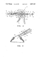
FIG. 2 is a longitudinal sectional view of the invention; and
FIG. 3 is an enlarged fragmentary view, illustrating the end of the barrel of the device of FIG. 2 in position for inserting a valve stem in a rim.
DESCRIPTION OF THE PREFERRED EMBODIMENTS
Referring now to the drawings, there is shown generally at 10 a valve inserting tool constructed in accordance with the invention. More particularly the valve inserting tool includes a tubular barrel 11 removably affixed to a handle mechanism 12 within which is carried a reciprocable push rod or shaft 13. The illustrated handle mechansim 12 employs a trigger arrangement of the type commonly utilized in caulking guns for advancing the push rod as will be hereinafter more fully explained. However it is fully contemplated that other and different types of equipment may be employed with the handle mechanism for advancing and retracting the push rod. For example, a number of types of equivalent trigger systems are available, or the handle mechanism might employ a rotary lever in conjunction with a threaded push rod. It might also incorporate an air cylinder with the push rod 13 connected to the piston thereof.
As best illustrated in FIGS. 2 and 3, the tubular barrel 11 comprises a cylindrical loading section 14 having an inside diameter sufficiently large to readily accommodate a valve stem 15, and a funnel-shaped exit section 16 whose walls converge toward an exit orifice 17 to compress the base of the valve stem as it is advanced prior to ejection. The exit section 16 is formed at the end with a tip 18 of reduced external diameter. More particularly, the tip comprises a reduced diameter flange 19 projecting from the end of the funnel shaped section 16 so as to define an annular end bearing wall 20 thereon. The flange 19 is so dimensioned as to be received within a conventional valve stem opening 21 in a rim 22 for a tubeless tire 23. The width of the flange 19 is approximately equal to the thickness of the rim material so that, as seen in FIG. 3, with the annular end bearing wall 20 seated against the rim, the end of the flange will be approximately flush with the inner surface of the rim 22. Thus, as will be hereinafter more fully explained, as the compressed base of the valve stem 15 emerges from the orifice 17 it will seat against the interior surface of the rim.
The handle mechanism 12 includes a pistol-type grip 24 of generally rectangular configuration by which the tool is held while in use. The grip is open at the top and bottom and carries at its forward end a coupler, indicated generally at 25, for affixing the barrel 11. The coupler more specifically comprises a base plate 26 with a mounting flange 27 projecting forwardly therefrom adapted to be received in the end of the entry section 14 of the tubular barrel 11. Diametrically opposed pins 28 projecting from the mounting flange cooperate with mating bayonet slots 29 in the barrel in the conventional manner to releasably couple the barrel to the handle mechanism. It is contemplated that alternatively the interior of the barrel may be provided with threads for mating with complementary threads on the mounting flange 27 whereby the barrel may be removably coupled to the handle mechanism. A central aperture 30 is provided in the base plate and mounting flange for passage of the push rod 13.
A trigger 31 positioned forwardly of the grip 24 is pivotally mounted within the grip above the push rod upon a transversely extending shaft 32. First and second push rod drive grips 33 and 34, located forwardly of the upper portion of the trigger 31 and in operational contact with the trigger have openings 35 and 36, respectively, through which the push rod loosely passes. A compression spring 37 surrounding the push rod between the base plate 26 and second push rod drive grip 34 urges the drive grips against the trigger. A release lever 38 extending through an aperture 39 in the rear wall of the pistol-type grip 24 has an opening 40 through which the push rod 13 loosely passes. The release lever has a rearwardly extending lip 41 which bears against the grip 24 to serve as a fulcrum for the lever, and a thumb tab 42 by which it can be manually depressed to release type push rod. A coil spring 43 surrounding the push rod bears against the trigger 31 and the release lever 38 to normally urge the trigger forward and the release lever rearwardly to a canted position where-at it grips the push rod 13 around the opening 40 in the conventional manner and prevents rearward movement of the push rod.
Conventional tubeless tire valve stems are generally available in a number of standard lengths to serve different applications. Thus, for example, there may be four standard lengths for automobile valve stems and two standard lengths for truck stems. The push rod 13 of the invention serves both to advance the valve stem 15 through the insertion tool and into the rim, and to provide a visual indication of the point at which the stem is properly positioned with respect to the rim. To that end, the push rod or shaft 13 is of some what greater length than the assembled tubular barrel 11 and handle mechanism 12. At its forward end there is affixed to the push rod a fitting 44 internally threaded as at 45 for receiving the threaded end of the barrel 46 of the valve stem 15. Such valve stems conventionally include a resilient sleeve 47 bonded to the barrel and having an enlarged base 48 with tapered walls 49, and an annular flange 50 spaced therefrom and defining a recess 51 between the flange and enlarged base. The recessed area has a diameter similar to the diameter of the opening 21 in the rim 22, and the width of the recess is equivalent to the wall thickness of the rim.
The push rod or shaft 13 is of sufficient length to extend rearwardly beyond the grip 24 for some distance with the shaft fully advanced for insertion of a valve stem. An adjustable knob 52 carried on the push rod has a set screw 53 by which it may be affixed at selected positions along the push rod. The knob is utilized in turning the pushrod for connecting it to an disconnecting it from the valve stem, and to that end may be provided with a knurled surface 54. A compression spring 55 encircles the push rod between the grip 24 and the knob 52. The spring may serve to indicate the position of the valve stem as well as to retract the push rod when the release lever 38 is depressed. Thus, by suitably locating the knob 52 along the push rod, it can be positioned to indicate that a particular length valve stem is properly seated in the rim when the knob first engages the spring 55 against the grip 24, or when it has fully compressed the spring. To assist in setting the knob, there may be provided on the push rod a series of index marks 56 indicating where the knob should be positioned for each standard length valve stem. Alternatively, the index marks themselves may be so positioned on the push rod to visually indicate directly, either relative to the spring 55 or to the grip 24, when the rod has been advanced sufficiently to permit seating of the valve stem.
Reviewing briefly operation of the invention, in order to install a valve stem the barrel 11 is removed from the handle mechansim 12 by turning counterclockwise and separating to disengage the pins 28 from the bayonet slots 29. An appropriate valve stem 15 is then attached to the push rod 13 by screwing the end of the barrel 46 into the fitting 44. A lubricant, such as ordinary lubricating grease or pertroleum jelly, is preferably applied to the enlarged base 48 and tapered walls 49 of the valve stem to facilitate passage of the valve stem through the funnel shaped exit section 16 of the barrel 11. The barrel is then re-attached to the handle mechanism, care being taken to insure that the push rod and attached valve stem are sufficiently retracted to readily permit locking of the pins 28 in the bayonet slots 29 without the base 48 being compressed within the funnel section 16. The knob 52 is then set axially along the push rod or shaft 13 at the appropriate location for the particular valve stem affixed thereto if the knob is to be used as the visual indicator or, as described above, the index marks 56 may be utilized directly to indicate the depth of insertion of the valve stem.
The tip 18 of the tool is then placed against the rim with the flange 19 in the opening 21 and the annular end bearing wall 20 held securely against the surface of the rim. The trigger 31 of the grip 24 is operated in the usual manner to incrementally advance the push rod or shaft 13. Thus, as will be apparent in FIG. 2, when the trigger is pulled back the drive grips 33 and 34 are canted forwardly to grip the push rod and cause it to advance. When the trigger is released the compression spring 37 urges the grips 33 and 34 back to an upright position and the trigger to its forward position. The release lever 38 grips the push rod to prevent it form retracting.
Repeated operation of the trigger 31 thus causes the push rod to advance the valve stem 15 along the barrel and the funnel shaped exit section 16 thereof, in turn compressing the enlarged base 49. As illustrated in FIG. 3, the valve stem moves along the funnel-shaped section 16 from the solid line position and, as it reaches the position shown in broken lines, the enlarged base 48 moves out of the exit orifice 17 and snaps into position against the inside surface of the rim. The operator will not only be able to feel when the base has seated inside the rim since the valve stem can not be easily withdrawn, but will also be able to visually observe from the position of the knob 52 and/or the index marks 56 when the base is in position, whereupon advancement of the valve stem is discontinued with the annular flange 50 still within the barrel. With the base 48 inside the rim, the release lever 38 is depressed to allow the push rod 13 to retract and pull the base securely against the rim. The trigger 31 may again be operated to eject the remainder of the valve stem from the barrel. As it emerges from the exit orifice, the annular flange 50 seats against the outer surface of the rim, and the walls of the recess 51 expand outwardly to engage the walls of the valve stem opening 21 to complete the installation of the valve stem as shown in broken line in FIG. 3. The push rod is then rotated by means of the knob 52 to unscrew the valve stem from the fitting 44.
It is to be understood that the forms of the invention herewith shown and described are to be taken as preferred embodiments of the same, but that various changes in the shape, size and arrangement of parts may be reserted to without departing form the spirit of the invention.

Claims (8)

What is claimed is:
1. A tool for inserting a tubeless tire valve stem having an enlarged base into the opening of a rim from the exterior of the rim, comprising a tubular barrel having an exit orifice defined by an end thereof, which end is adapted to mate with said opening, said tubular barrel including a loading section and a funnel-shaped exit section gradually decreasing in diameter from said loading section to said exit orifice, shaft means adapted to extend axially within said tubular barrel, including means for releasably connecting said shaft to said valve stem, and means for advancing said shaft axially within said tubular barrel to thereby advance said valve stem along said exit section and eject said base through said orifice into said opening, said means for advancing said shaft including a handle mechanism removably affixed to said loading section of said tubular barrel to permit the affixing of different size barrels to said handle mechanism for different standard size valve stems, a trigger pivotally mounted in said handle mechanism, said trigger being operatively connected to said shaft whereby said shaft is incrementally advanced upon each retraction of said trigger, and including index means on said shaft for indicating in cooperation with said handle mechanism the position at which said shaft has been advanced sufficiently to eject said base through said orifice and seat it in said opening for each of several diffrent standard length stems.
2. A tool for inserting a tubeless tire valve stem as claimed in claim 1, wherein said tubular barrel includes a tip of reduced external diameter adapted to be received within said opening whereby said exit orifice mates with said opening.
3. A tool for inserting a tubeless tire valve stem as claimed in claim 2, wherein said tip comprises a flange of reduced diameter projecting from the end of said funnel-shaped exit section and defining an annular end bearing wall on said end supporting said flange.
4. A tool for inserting a tubeless tire valve stem as claimed in claim 3, wherein the external diameter of said flange is substantially equal to the diameter of said opening, and the width of said flange is substantially equal to the thickness of the rim in the area surrounding said opening.
5. A tool for inserting a tubeless tire valve stem as claimed in claim 1, wherein said valve stem includes an externally threaded end and said means for releasably connecting said shaft to said valve stem includes an internally threaded fitting at the end of said shaft for receiving the threaded end of said valve stem.
6. A tool for inserting a tubeless tire valve stem as claimed in claim 1, wherein said index means comprises a series of spaced marks on said shaft, each said mark indicating the position of the base of a different on of the standard lengths of said valve stems relative to said orifice.
7. A tool for inserting a tubeless tire valve stem as claimed in claim 1, wherein said valve stem includes an externally threaded end portion and said means for releasably connecting said shaft to said valve stem includes an internally threaded fitting at the end of said shaft adapted to mate with the threaded end of said valve stem, and said index means comprises a knob adjustable positionable along said shaft behind said handle mechanism, said knob being adapted for setting at selected positions along said shaft to indicate the position of the base of a different one of the standard lengths of said valve stems relative to said orifice, and for rotating said shaft about its longitudinal axis to connect and disconnect said shaft and valve stem.
8. A tool for inserting a tubeless tire valve stem as claimed in claim 1, including a base plate on said handle mechanism, a mounting flange extending outwardly from said base plate for insertion into the end of said loading section of said tubular barrel, at least one pin projecting radially outwardly from said mounting flange, and a locking slot in the wall of said tubular barrel for receiving said pin and releasably connecting said tubular barrel to said handle mechanism.
US07/085,344 1987-08-14 1987-08-14 Tubeless tire valve stem inserter Expired - Fee Related US4807343A (en)

Priority Applications (1)

Application Number Priority Date Filing Date Title
US07/085,344 US4807343A (en) 1987-08-14 1987-08-14 Tubeless tire valve stem inserter

Applications Claiming Priority (1)

Application Number Priority Date Filing Date Title
US07/085,344 US4807343A (en) 1987-08-14 1987-08-14 Tubeless tire valve stem inserter

Publications (1)

Publication Number Publication Date
US4807343A true US4807343A (en) 1989-02-28

Family

ID=22190985

Family Applications (1)

Application Number Title Priority Date Filing Date
US07/085,344 Expired - Fee Related US4807343A (en) 1987-08-14 1987-08-14 Tubeless tire valve stem inserter

Country Status (1)

Country Link
US (1) US4807343A (en)

Cited By (24)

* Cited by examiner, † Cited by third party
Publication number Priority date Publication date Assignee Title
US5054821A (en) * 1988-03-03 1991-10-08 Cordis Corporation Sterile sleeve/connector assembly
US5097580A (en) * 1990-07-02 1992-03-24 Story Albert J Apparatus for installing and removing valve stems
US5146676A (en) * 1991-10-30 1992-09-15 Westinghouse Electric Corp. Hand-actuated spring clip insertion tool
US5218750A (en) * 1991-09-05 1993-06-15 The United States Of America As Represented By The Secretary Of The Navy Method of mounting a spool mount in an opening in the hull of a vessel
US5636436A (en) * 1994-12-28 1997-06-10 Martin; Douglas A. Extended coaxial cable ejection device
US5803108A (en) * 1996-12-09 1998-09-08 International Marketing, Inc. Tool and method for inserting a filter element into the valve stem of a wheel assembly
US5813104A (en) * 1996-12-24 1998-09-29 Quick; Thomas W. Sucker rod thread protector removal tool
US6152165A (en) * 1998-03-03 2000-11-28 Alma Trading Incorporated Valve core mounting and dismounting tool
US6209183B1 (en) * 1999-10-19 2001-04-03 Trw Inc. Bushing installation tool
US6324739B1 (en) * 1999-04-16 2001-12-04 Nippon Pillar Packing Co., Ltd. Inner ring press-insertion jig for a pipe joint made of resin
US6481083B1 (en) 1999-06-25 2002-11-19 Burke E. Porter Machinery Company Robotic apparatus and method for mounting a vale stem on a wheel rim
US6574843B1 (en) 2001-07-12 2003-06-10 Thomas J. Meadows Method and apparatus for installing and replacing valve stems
US6722011B1 (en) * 2003-05-09 2004-04-20 Bradley Bacon Apparatus and method for installing a c-clip
US6886231B2 (en) 1999-06-25 2005-05-03 Burke E. Porter Machinery Company Robotic apparatus and method for mounting a valve stem on a wheel rim
US7017247B2 (en) 2001-05-18 2006-03-28 Dave Detzel Valve stem remover and installer tool kit
WO2013149305A1 (en) * 2012-04-05 2013-10-10 Dwyer Christopher John Tyre valve tool
US8621991B1 (en) * 2010-08-23 2014-01-07 Rodolfo Lopez Pistol grip spring compressor system and method for maintaining compression on a valve spring
US9517551B2 (en) * 2013-06-06 2016-12-13 LR Inventions, LLC Fuel injector assembly apparatus and method
US9616719B1 (en) 2014-07-17 2017-04-11 Cory R. Jensen Valve cap and core tool
US20180119834A1 (en) * 2015-06-05 2018-05-03 Todd Johnson Valve stem assemblies
CN108870075A (en) * 2017-05-10 2018-11-23 深圳市兰洋科技有限公司 Gas cylinder valve handwheel handgrip and gas cylinder valve handwheel rotating device
GR1009449B (en) * 2017-10-25 2019-01-29 Δημητριος Νικολαου Μαραγκουδακης Damaged tyre's valve replacement gun
CN109397182A (en) * 2018-09-27 2019-03-01 北京车和家信息技术有限公司 Buckle installation tool
US20190145535A1 (en) * 2016-09-22 2019-05-16 Raymond H. Smith Grooved Valve Stems for Wheel-Side Installation

Citations (9)

* Cited by examiner, † Cited by third party
Publication number Priority date Publication date Assignee Title
US1466992A (en) * 1922-03-07 1923-09-04 Daniel A Craun Pin-inserting tool
US1552645A (en) * 1922-12-08 1925-09-08 Herbert S Powell Oilless joint for the springs of motor vehicles
US1601324A (en) * 1924-04-07 1926-09-28 Tom C Reynolds Hammer
US2430532A (en) * 1945-02-20 1947-11-11 Ralph W Rayburn Pin setting tool
US2438642A (en) * 1944-11-20 1948-03-30 Ralph Walsh Apparatus for inserting valve elements
US2866492A (en) * 1954-08-20 1958-12-30 Goodyear Tire & Rubber Tubeless tire valve
US3387354A (en) * 1966-07-20 1968-06-11 Harry J. Mossberg Valve inserting device
US3750258A (en) * 1971-09-16 1973-08-07 J Sampo Insertion tool for tire valve stems
US3852839A (en) * 1972-08-09 1974-12-10 Blt Ind Tire tool

Patent Citations (9)

* Cited by examiner, † Cited by third party
Publication number Priority date Publication date Assignee Title
US1466992A (en) * 1922-03-07 1923-09-04 Daniel A Craun Pin-inserting tool
US1552645A (en) * 1922-12-08 1925-09-08 Herbert S Powell Oilless joint for the springs of motor vehicles
US1601324A (en) * 1924-04-07 1926-09-28 Tom C Reynolds Hammer
US2438642A (en) * 1944-11-20 1948-03-30 Ralph Walsh Apparatus for inserting valve elements
US2430532A (en) * 1945-02-20 1947-11-11 Ralph W Rayburn Pin setting tool
US2866492A (en) * 1954-08-20 1958-12-30 Goodyear Tire & Rubber Tubeless tire valve
US3387354A (en) * 1966-07-20 1968-06-11 Harry J. Mossberg Valve inserting device
US3750258A (en) * 1971-09-16 1973-08-07 J Sampo Insertion tool for tire valve stems
US3852839A (en) * 1972-08-09 1974-12-10 Blt Ind Tire tool

Cited By (35)

* Cited by examiner, † Cited by third party
Publication number Priority date Publication date Assignee Title
US5054821A (en) * 1988-03-03 1991-10-08 Cordis Corporation Sterile sleeve/connector assembly
US5097580A (en) * 1990-07-02 1992-03-24 Story Albert J Apparatus for installing and removing valve stems
US5218750A (en) * 1991-09-05 1993-06-15 The United States Of America As Represented By The Secretary Of The Navy Method of mounting a spool mount in an opening in the hull of a vessel
US5146676A (en) * 1991-10-30 1992-09-15 Westinghouse Electric Corp. Hand-actuated spring clip insertion tool
GB2260928B (en) * 1991-10-30 1995-05-31 Westinghouse Electric Corp Hand-actuated spring clip insertion tool
US5636436A (en) * 1994-12-28 1997-06-10 Martin; Douglas A. Extended coaxial cable ejection device
US5803108A (en) * 1996-12-09 1998-09-08 International Marketing, Inc. Tool and method for inserting a filter element into the valve stem of a wheel assembly
US5813104A (en) * 1996-12-24 1998-09-29 Quick; Thomas W. Sucker rod thread protector removal tool
US6152165A (en) * 1998-03-03 2000-11-28 Alma Trading Incorporated Valve core mounting and dismounting tool
US6324739B1 (en) * 1999-04-16 2001-12-04 Nippon Pillar Packing Co., Ltd. Inner ring press-insertion jig for a pipe joint made of resin
US6481083B1 (en) 1999-06-25 2002-11-19 Burke E. Porter Machinery Company Robotic apparatus and method for mounting a vale stem on a wheel rim
US7600306B2 (en) 1999-06-25 2009-10-13 Burke E. Porter Machinery Company Robotic apparatus and method for mounting a valve stem on a wheel rim
US20070107183A1 (en) * 1999-06-25 2007-05-17 Burke E. Porter Machinery Company, A Corporation Of The State Of Michigan Robotic apparatus and method for mounting a valve stem on a wheel rim
US6886231B2 (en) 1999-06-25 2005-05-03 Burke E. Porter Machinery Company Robotic apparatus and method for mounting a valve stem on a wheel rim
US20050177989A1 (en) * 1999-06-25 2005-08-18 Burke E. Porter Machinery Company, A Corporation Of The State Of Michigan Robotic apparatus and method for mounting a valve stem on a wheel rim
US7185410B2 (en) 1999-06-25 2007-03-06 Burke E. Porter Machinery Company Robotic apparatus and method for mounting a valve stem on a wheel rim
US6209183B1 (en) * 1999-10-19 2001-04-03 Trw Inc. Bushing installation tool
US7017247B2 (en) 2001-05-18 2006-03-28 Dave Detzel Valve stem remover and installer tool kit
US6574843B1 (en) 2001-07-12 2003-06-10 Thomas J. Meadows Method and apparatus for installing and replacing valve stems
US6722011B1 (en) * 2003-05-09 2004-04-20 Bradley Bacon Apparatus and method for installing a c-clip
US8621991B1 (en) * 2010-08-23 2014-01-07 Rodolfo Lopez Pistol grip spring compressor system and method for maintaining compression on a valve spring
WO2013149305A1 (en) * 2012-04-05 2013-10-10 Dwyer Christopher John Tyre valve tool
US9517551B2 (en) * 2013-06-06 2016-12-13 LR Inventions, LLC Fuel injector assembly apparatus and method
US9616719B1 (en) 2014-07-17 2017-04-11 Cory R. Jensen Valve cap and core tool
USD883914S1 (en) 2015-06-05 2020-05-12 Todd Johnson Valve stem
US10539247B2 (en) * 2015-06-05 2020-01-21 Todd Johnson Valve stem assemblies
US20180119834A1 (en) * 2015-06-05 2018-05-03 Todd Johnson Valve stem assemblies
US10969027B2 (en) 2015-06-05 2021-04-06 Todd Johnson Valve stem assemblies
US11686401B2 (en) 2015-06-05 2023-06-27 Todd Johnson Valve stem assemblies
US20190145535A1 (en) * 2016-09-22 2019-05-16 Raymond H. Smith Grooved Valve Stems for Wheel-Side Installation
US11137085B2 (en) * 2016-09-22 2021-10-05 Raymond H. Smith, Jr. Grooved valve stems for wheel-side installation
CN108870075A (en) * 2017-05-10 2018-11-23 深圳市兰洋科技有限公司 Gas cylinder valve handwheel handgrip and gas cylinder valve handwheel rotating device
CN108870075B (en) * 2017-05-10 2024-03-22 深圳市兰洋科技有限公司 Gas cylinder valve hand wheel tongs and gas cylinder valve hand wheel rotating device
GR1009449B (en) * 2017-10-25 2019-01-29 Δημητριος Νικολαου Μαραγκουδακης Damaged tyre's valve replacement gun
CN109397182A (en) * 2018-09-27 2019-03-01 北京车和家信息技术有限公司 Buckle installation tool

Similar Documents

Publication Publication Date Title
US4807343A (en) Tubeless tire valve stem inserter
EP0828573B1 (en) A fastener installation tool including a hydraulically actuated head piston
US4528735A (en) Tire tool
US4207564A (en) Piston overtravel indicator
US20090107229A1 (en) Tire pressure gauge with cap wrench
US6574843B1 (en) Method and apparatus for installing and replacing valve stems
US3301282A (en) Bleeding tool and apparatus for hydraulic systems
EP0665395B1 (en) Valve assembly
US5097580A (en) Apparatus for installing and removing valve stems
US6293297B1 (en) Air valve housing with pressure indicator
US6074118A (en) Automatic device for locking a vehicle wheel onto balancing machine shaft
US5839180A (en) Stud installer for wheel studs
US3750258A (en) Insertion tool for tire valve stems
EP1288025B1 (en) Safety device for pressurising an envelope at risk of bursting
US6944924B2 (en) Valve stem puller and valve stem core tool
EP0616911A2 (en) Arrangement for inflating tubeless wheels
US5216793A (en) Hose fitting removal apparatus
AU575809B2 (en) Tire valve connector
US4361944A (en) Barrel lock ferrule extractor
US7017247B2 (en) Valve stem remover and installer tool kit
US3833995A (en) Valve stem and valve stem tool
US3945273A (en) Tire repair tool
US20230234195A1 (en) Valve stem insertion device
US4584769A (en) Extractor for increment borer
EP0015671A1 (en) Tyre valve

Legal Events

Date Code Title Description
AS Assignment

Owner name: CHEMI-TROL CHEMICAL CO., SANDUSKY COUNTY, OH A COR

Free format text: ASSIGNMENT OF ASSIGNORS INTEREST.;ASSIGNOR:WADSWORTH, THOMAS P.;REEL/FRAME:004771/0982

Effective date: 19870810

Owner name: CHEMI-TROL CHEMICAL CO.,OHIO

Free format text: ASSIGNMENT OF ASSIGNORS INTEREST;ASSIGNOR:WADSWORTH, THOMAS P.;REEL/FRAME:004771/0982

Effective date: 19870810

REMI Maintenance fee reminder mailed
LAPS Lapse for failure to pay maintenance fees
FP Lapsed due to failure to pay maintenance fee

Effective date: 19930228

STCH Information on status: patent discontinuation

Free format text: PATENT EXPIRED DUE TO NONPAYMENT OF MAINTENANCE FEES UNDER 37 CFR 1.362