US4812831A - Key switch with controllable illumination - Google Patents
Key switch with controllable illumination Download PDFInfo
- Publication number
- US4812831A US4812831A US07/012,971 US1297187A US4812831A US 4812831 A US4812831 A US 4812831A US 1297187 A US1297187 A US 1297187A US 4812831 A US4812831 A US 4812831A
- Authority
- US
- United States
- Prior art keywords
- illumination
- keyboard
- source
- switch
- layer
- Prior art date
- Legal status (The legal status is an assumption and is not a legal conclusion. Google has not performed a legal analysis and makes no representation as to the accuracy of the status listed.)
- Expired - Fee Related
Links
Images


Classifications
-
- H—ELECTRICITY
- H01—ELECTRIC ELEMENTS
- H01H—ELECTRIC SWITCHES; RELAYS; SELECTORS; EMERGENCY PROTECTIVE DEVICES
- H01H13/00—Switches having rectilinearly-movable operating part or parts adapted for pushing or pulling in one direction only, e.g. push-button switch
- H01H13/70—Switches having rectilinearly-movable operating part or parts adapted for pushing or pulling in one direction only, e.g. push-button switch having a plurality of operating members associated with different sets of contacts, e.g. keyboard
- H01H13/78—Switches having rectilinearly-movable operating part or parts adapted for pushing or pulling in one direction only, e.g. push-button switch having a plurality of operating members associated with different sets of contacts, e.g. keyboard characterised by the contacts or the contact sites
- H01H13/807—Switches having rectilinearly-movable operating part or parts adapted for pushing or pulling in one direction only, e.g. push-button switch having a plurality of operating members associated with different sets of contacts, e.g. keyboard characterised by the contacts or the contact sites characterised by the spatial arrangement of the contact sites, e.g. superimposed sites
-
- G—PHYSICS
- G06—COMPUTING; CALCULATING OR COUNTING
- G06F—ELECTRIC DIGITAL DATA PROCESSING
- G06F1/00—Details not covered by groups G06F3/00 - G06F13/00 and G06F21/00
- G06F1/26—Power supply means, e.g. regulation thereof
- G06F1/32—Means for saving power
- G06F1/3203—Power management, i.e. event-based initiation of a power-saving mode
- G06F1/3234—Power saving characterised by the action undertaken
- G06F1/325—Power saving in peripheral device
- G06F1/3271—Power saving in keyboard
-
- H—ELECTRICITY
- H01—ELECTRIC ELEMENTS
- H01H—ELECTRIC SWITCHES; RELAYS; SELECTORS; EMERGENCY PROTECTIVE DEVICES
- H01H13/00—Switches having rectilinearly-movable operating part or parts adapted for pushing or pulling in one direction only, e.g. push-button switch
- H01H13/70—Switches having rectilinearly-movable operating part or parts adapted for pushing or pulling in one direction only, e.g. push-button switch having a plurality of operating members associated with different sets of contacts, e.g. keyboard
- H01H13/702—Switches having rectilinearly-movable operating part or parts adapted for pushing or pulling in one direction only, e.g. push-button switch having a plurality of operating members associated with different sets of contacts, e.g. keyboard with contacts carried by or formed from layers in a multilayer structure, e.g. membrane switches
-
- H—ELECTRICITY
- H01—ELECTRIC ELEMENTS
- H01H—ELECTRIC SWITCHES; RELAYS; SELECTORS; EMERGENCY PROTECTIVE DEVICES
- H01H2217/00—Facilitation of operation; Human engineering
- H01H2217/022—Part of keyboard not operable
-
- H—ELECTRICITY
- H01—ELECTRIC ELEMENTS
- H01H—ELECTRIC SWITCHES; RELAYS; SELECTORS; EMERGENCY PROTECTIVE DEVICES
- H01H2217/00—Facilitation of operation; Human engineering
- H01H2217/038—Prompting
-
- H—ELECTRICITY
- H01—ELECTRIC ELEMENTS
- H01H—ELECTRIC SWITCHES; RELAYS; SELECTORS; EMERGENCY PROTECTIVE DEVICES
- H01H2219/00—Legends
- H01H2219/002—Legends replaceable; adaptable
- H01H2219/018—Electroluminescent panel
-
- H—ELECTRICITY
- H01—ELECTRIC ELEMENTS
- H01H—ELECTRIC SWITCHES; RELAYS; SELECTORS; EMERGENCY PROTECTIVE DEVICES
- H01H2225/00—Switch site location
- H01H2225/03—Different type of switches
-
- H—ELECTRICITY
- H01—ELECTRIC ELEMENTS
- H01H—ELECTRIC SWITCHES; RELAYS; SELECTORS; EMERGENCY PROTECTIVE DEVICES
- H01H2239/00—Miscellaneous
- H01H2239/008—Static electricity considerations
-
- H—ELECTRICITY
- H01—ELECTRIC ELEMENTS
- H01H—ELECTRIC SWITCHES; RELAYS; SELECTORS; EMERGENCY PROTECTIVE DEVICES
- H01H2239/00—Miscellaneous
- H01H2239/022—Miscellaneous with opto-electronic switch
-
- H—ELECTRICITY
- H01—ELECTRIC ELEMENTS
- H01H—ELECTRIC SWITCHES; RELAYS; SELECTORS; EMERGENCY PROTECTIVE DEVICES
- H01H2239/00—Miscellaneous
- H01H2239/032—Anti-tamper
-
- Y—GENERAL TAGGING OF NEW TECHNOLOGICAL DEVELOPMENTS; GENERAL TAGGING OF CROSS-SECTIONAL TECHNOLOGIES SPANNING OVER SEVERAL SECTIONS OF THE IPC; TECHNICAL SUBJECTS COVERED BY FORMER USPC CROSS-REFERENCE ART COLLECTIONS [XRACs] AND DIGESTS
- Y02—TECHNOLOGIES OR APPLICATIONS FOR MITIGATION OR ADAPTATION AGAINST CLIMATE CHANGE
- Y02D—CLIMATE CHANGE MITIGATION TECHNOLOGIES IN INFORMATION AND COMMUNICATION TECHNOLOGIES [ICT], I.E. INFORMATION AND COMMUNICATION TECHNOLOGIES AIMING AT THE REDUCTION OF THEIR OWN ENERGY USE
- Y02D10/00—Energy efficient computing, e.g. low power processors, power management or thermal management
Definitions
- This invention relates to the field of keyboards of the back lighted membrane type.
- the use of the illumination in keyboards of the membrane or lamina type is well known, particularly where the graphic layer, usually the top layer of a membrane switch is rendered to provide a dead front or blank appearance.
- the provision of a dead front or unidirectional mask for a membrane keyboard switch is generally accomplished by the choice of dark or black inks utilized in the printing of the graphic portions of the switch. This is typically done for esthetic reasons in order to provide a contrast between a given switch point or the colors chosen for the graphics.
- Dead front coverage may be utilized over the entire switch face or selectively in portions of the switch. When this is done, it is necessary to illuminate the graphics from the rear which is termed "back lighting" and is accomplished by making the membrane switch construction relatively transparent except for the dead front top layer which contains the graphics.
- a variety of sources of illumination for back lighting have been employed. Included are incandescent bulbs which have the advantage of relatively low cost but the disadvantages of heat generation and relatively high energy consumption and a certain fragility caused by the need for a fine filament typical of incandescent bulbs. Also, fluorescent light sources have been employed with less of a consumption of energy but also having a certain fragility and a relatively higher cost.
- a third type of illumination now beginning to be used relative to display panels employs the phenomena of electroluminescence which shall be here termed EL. From an initial shortcoming of relatively high cost and limitations in regard to colors available, the EL concept has been extended first from displays made of glass to light sources, wherein the electroluminescing powders can be printed on the substrates such as polyester film by silk screening techniques.
- a third aspect of the background of the invention relates to the fact that the desirability to limit access to the controls of electronic devices such as computer terminals, T.V. sets, control monitors, and the like.
- electronic devices such as computer terminals, T.V. sets, control monitors, and the like.
- the horizontal, vertical and contrast controls of a television set might be sufficiently concealed or made "invisible” as to allow only an authorized person to adjust the picture on such receiver.
- computer and telecommunication monitors and more particularly, to such CRT displays as are now used in aircraft and on industrial controls.
- most of these controls are visible either on the front of the display of the device or are located in an obvious position on the rear thereof and may be easily manipulated or tampered with or indeed, accidentally moved to the end dissatisfaction of the user.
- This invention relates to an illuminated membrane keyboard or key switch wherein the illumination is controlled by a light beam arrangement with both the light beam and the keyboard nominally hidden from view. This is accomplished by providing the illumination beneath the membrane to back light such, with the upper or graphic layer of the keyboard being opaque without such back lighting.
- the light beam is provided in a preferred embodiment through the use of an infrared LED operating at a frequency above that which the human eye can detect in conjunction with appropriate phototransistors or photodiodes arranged to sense the presence or absence of such light beam energy.
- the LED and photodiodes are mounted in a bezel which is opaque to visible light but will transmit light in the infrared range.
- a circuit is provided which is responsive to the breaking of a light beam as by a finger or stylus touching the keyboard in a selective position to turn on the illumination and backlight the keyboard so that it may be utilized.
- a time is provided to automatically cut off the illumination following a predetermined and preselected period of time to both obscure the keyboard from sight and to save energy, extend the life of the source of illumination and provide the "invisible" feature.
- the source of the illumination utilized is an EL layer positioned within the lamina membrane keyboard.
- the arrangement of the invention may be employed in a wide variety of uses in conjunction with keyboards of normal construction utilized for computers, telecommunication, data processing, industrial controls, and placed in a front position or alternatively, placed to the rear of similar devices including television sets, allowing only competent technicians to adjust such through the special knowledge of the hidden arrangement.
- FIG. 1 is a perspective of a data terminal including a keyboard and additionally including the auxiliary keyboard of the present invention adjacent the normal keyboard position;
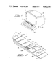
- FIG. 2 is an enlarged schematic view in perspective and partial section showing the various laminations of the keyboard in accordance with the present invention
- FIG. 3 is a schematic view of the keyboard of the present invention in conjunction with preferred circuit arrangement therefore;
- FIG. 4 is a view similar to FIG. 3 but with an alternative arrangement for the light beam feature.
- FIG. 5 is a sectional view of a portion of the rear of an electronic apparatus such as a television set showing in partial section an arrangement for mounting the keyboard of the present invention.
- a data terminal labeled 10 including a display 12 mounted in a terminal housing 14.
- a keyboard 16 which may be either integral therewith or as shown separate therefrom.
- the keyboard of the invention Positioned above the normal keyboard face is the keyboard of the invention which is in a sense an auxiliary keyboard and while shown mounted above the normal keyboard in this preferred embodiment, could be mounted to the right, left, rear or in any convenient position on the keyboard housing.
- the keyboard 18 is normally made to contain a limited number of functions such as six or ten or twelve, and is to be used for controlling the various modes or functions of display or other attributes of the terminal 10 which it serves.
- the keyboard 18 is made to have a dead front or opaque appearance as indicated in FIG. 1 in order for it to remain hidden, except when backlighted by a controlled illumination.
- a dead front keyboards in membrane keyboard technology is well known and is employed in whole or in part in a wide variety of keyboards in use today.
- the technique is accomplished by the selection of inks applied during the processing of the top layer of the keyboard as one of a series of the finite steps employed in such printing to achieve preferred colors and geometry of the key symbols.
- the provision of an opaque appearance may be accomplished by depositing the inks either on the top surface of the top layer or preferably on the undersurface of the top layer as the first step of the series of printing steps to follow.
- dead fronting is typically arranged in a flat black or a flat brown color and may be done in a manner so that virtually no key location can be observed without backlighting.
- the top layer 20 is the graphic layer which is typically made of a polyester film on the order of 0.005 to 0.007 inches in thickness. Key locations are shown as elements 21.
- the graphic ink for such is provided on the undersurface of 20 to protect it from use.
- a layer of adhesive 22 and thereafter a layer 24 which is the EL lamp assembly and is comprised of suitably selected phosphorescing inks or powders embedded in a matrix of adhesive and bonded to a polyester film on the order of 0.005 inches in thickness, with suitable electrodes applied to the rear surface thereof to produce an electric field which excites the powders of the EL assembly and causes the illumination phenomena to occur.
- a coating of adhesive shown as 26 beneath the EL lamp assembly.
- a grid 28 which is made of conductive ink and may be utilized for an ESD (electro static discharge) shield which may be optionally employed to isolate the circuit path beneath the EL lamp assembly from the field employed to excite such.
- ESD electro static discharge
- the ESD shield is laid down on the top surface of a plastic layer shown as 30 with a selective deposit of conductive material in the form of circuits 32 printed onto the bottom of 30.
- the circuits 32 form part of the switch function for keyboard 18.
- a layer 34 which may be alternatively a thin layer of polyester having a series of apertures or holes 36 therein which register with circuit traces 32 to define contact points and isolate the remaining parts of circuit traces in the switch, or can be dots of insulation silk screened on to a film to form a standoff.
- the next layer shown as 38 is made to contain the bottom circuit portion of the switch which is formed of polyester film and made to contain circuit traces which, when made to contact circuit 32 through holes 36, achieve a particular contact function. These circuits are shown as 40 and 42 and in the optional arrangement shown, form both sides of the circuit of the switch with the circuits 32 bridging the different paths 42 to effect switch closure.
- the final layer shown as 44 in FIG. 2 represents an adhesive layer applied to the bottom of the layer 38.
- the lamina package shown to include many layers be relatively thin and flexible so that pressure applied by finger or stylus upon a switch point location shown on the top layer as S, as in FIG. 3 will cause the switch points to be closed, the circuits 32 being pressed through the apertures 36 to contact the circuits 40 and 42.
- adhesives that are flexible during the life of use and that are maintained relatively thin as on the order of 0.001 inches in order to maintain the desired flexibility and thinness of the keyboard 18.
- keyboard 18 has been shown in the form of a strip, which is relatively long compared to its width, it can of course be rendered in a variety of different geometries including square or round, or indeed in any other desired configuration as long as it is maintained in a relatively planar state so as to function properly. With the keyboard 18 thus assembled, it may be applied to any flat substrate including a flat portion of the keyboard 16 to have an unilluminated appearance of an area of black or brown or suitable color chosen to fit in esthetically with the keyboard 16.
- the keyboard 18 may be placed elsewhere including to the rear of a data terminal or a television receiver as will be detailed relative to FIG. 5 hereinafter. Suffice to say, in operation the keyboard 18 will when nonilluminated, appear as a blank strip with the graphic key locations in essence invisible. When the EL lamp is excited, the back lighting effect will occur and the graphic symbols representing the key locations will show up to allow use. A depression by a finger or stylus of the top layer proximate to the key switch graphic representation will result in closure of the circuit shown as 32 with the circuits 40 and 42 to effect a switch closure. Removal of the stylus will result in an opening of these circuits by virtue of the characteristics of the polyester films 30 and 38 as held apart by the spacer structure in film 34, all as is standard in membrane switch functioning.
- the switch when the EL lamp is off, the switch will be invisible and when it is on, the various graphic key switch locations will be illuminated and ready for use.
- FIG. 3 a further and related aspect of the invention is shown wherein the keyboard 18 is mounted within a frame shown as 48 which is preferably set into the frame of keyboard 16 to become part of the facade of such keyboard.
- the frame 48 includes a series of apertures 49 as shown in FIG. 3 which may be either open or covered with a plastic suitably tinted to blend in with the frame 48 but made to be infrared transparent and visible light opaque.
- an infrared transmitter shown as 50 appropriately powered by leads 52 and, to the opposite side of the frame, a pair of receivers which may be phototransistors or photodiodes shown as 54 appropriately powered by leads such as 56.
- infrared LED 50 causes light to be broadcasted over the surface of keyboard 18 to be received by the receivers 54 which in turn detect such light and develop a signal indicating a received condition.
- U.S. Pat. Nos. 4,267,443 and 4,384,201 to Arthur B. Carroll, et al. for a teaching of the practice of utilizing infrared, transmitter and receiver devices to effect a switch function and to U.S. Pat. No. 3,764,813 to Clement, et al., which teaches, broadcasting a light beam over the surface of displays.
- a circuit shown as 60 which may be thought of as a circuit card or electronic package appropriately mounted in the electronic assembly which is served by the keyboard.
- Leads 52 and 56 are connected to board 60 and an appropriate driver circuit thereon shown as element 55.
- Board 60 further includes a logic circuit 62 in the form of a flip-flop or bi-stable device which as an on or off condition responsive to the signal level provided from the receiver elements 54 via leads 56.
- the output of element 62 is connected via lead 64 to a timer shown as 70 in FIG. 3 which operates to produce an output via lead 72 to an EL power supply shown as 74 which in turn supplies power to the EL source of illumination via leads 76.
- the timer 70 is made to provide an output holding power supply 74 on for a preselected and predetermined period of time ranging from a number of seconds to a number of minutes responsive to each pulse input from element 62.
- operation is as follows. Assuming that there is no stylus in the field of the light being generated by element 50 and received by element 54, the EL lamp will be off and the keyboard 18 will appear blank. Upon the insertion of the stylus interrupting the light beam, a change in sensed energy will be detected by elements 54 providing a voltage change via leads 60 as an input to the logic unit 62.
- Element 62 will then provide a pulse output via lead 64 to timer 70 turning the timer on which will produce an output via lead 72 to cut on power supply 74, in turn powering up the EL device via leads 76.
- the key locations 21 will then be illuminated by the EL device along the length of keyboard 18 to allow selection and actuation of an appropriate key or keys.
- each insertion of a stylus or finger into the light beam field will result in a further output from logic unit 62, resetting the timer 70 to continue to hold the power supply 74 in an on condition and maintain the keyboard illuminated.
- the keyboard in a normal condition will be off and opaque or dead front in appearance.
- the insertion of a finger or stylus into the beam field in accordance with the embodiment of FIG. 3, anywhere in the general key area will interrupt the light beam, resulting in the timer being actuated to turn on the illumination for a prefixed period of time. Thereafter, repeated insertion of the stylus into the beam field will maintain the illumination in an on condition until a certain period of time after the last insertion of the stylus.
- the key switch will be effectively hidden.
- FIG. 4 shows an alternative version of the keyboard heretofore described shown as a keyboard 80.
- Keyboard 80 includes a series of key points 82 with the keyboard being surrounded by the bezel 49 having apertures 51 which may be optionally covered with an infrared transparent plastic material serving as windows to photo devices. These devices are shown in FIG. 4 as transmitters 84 and 88, arranged at different ends of the keyboard producing beams of light detected by receivers 86 and 90.
- transmitters 84 and 88 arranged at different ends of the keyboard producing beams of light detected by receivers 86 and 90.
- FIG. 5 shows such an application wherein the switch 18 is mounted at the rear of a television chassis 11 in the frame 15.
- An internal circuit board 17 is used to support a plate 19 to which switch 18 is secured.
- Element 29 represents a grounded lead connected to a ground circuit on board 17.
- Element 98 represents the plastic frame covering the infrared transmitter 50 shown in FIG. 5. All adjustments for the display part of the set may be accommodated via 18, and an appropriate switch connection to the television set circuit.
- the LED element 50 and the receivers 54 were commercially available units as was the driver 55.
- the logic unit 62 a single low power relay and the timer was a standard 5-5-5 timer.
- the EL lamp and its power supply 74 were sourced from commercially available sources. This unit used a power supply of 120 voltage, 725 Hertz frequency, requiring 2.4 milliamperes in current.
- the duty cycle of the EL device could be reduced to less than one percent in certain applications such as in relation to the controls of a television receiver and only a few percent in relation to use with a computer or data terminal wherein the switch is used for mode control, programming functions, and/or display function control.
- This reduction in duty cycle would extend the life of the EL device, effectively many thousands of hours and well beyond the normal mean time to failure of the electronic apparatus served thereby.
- the power requirements which would be related to the expected duty cycle would be drastically reduced to the advantage of portable devices using the invention, circuit, and apparatus.
- the keyboard could have dimension of one inch by twelve inches and a thickness of less than fifty thousandths of an inch.
- the keyboard of the invention has been shown in conjunction with an attachment to or close proximity with, the electronic gear served thereby. It is contemplated that the invention keyboard may be utilized remote from such electronic gear to effect all the advantages heretofore ascribed thereto.
Abstract
Description
Claims (10)
Priority Applications (1)
| Application Number | Priority Date | Filing Date | Title |
|---|---|---|---|
| US07/012,971 US4812831A (en) | 1987-02-10 | 1987-02-10 | Key switch with controllable illumination |
Applications Claiming Priority (1)
| Application Number | Priority Date | Filing Date | Title |
|---|---|---|---|
| US07/012,971 US4812831A (en) | 1987-02-10 | 1987-02-10 | Key switch with controllable illumination |
Publications (1)
| Publication Number | Publication Date |
|---|---|
| US4812831A true US4812831A (en) | 1989-03-14 |
Family
ID=21757635
Family Applications (1)
| Application Number | Title | Priority Date | Filing Date |
|---|---|---|---|
| US07/012,971 Expired - Fee Related US4812831A (en) | 1987-02-10 | 1987-02-10 | Key switch with controllable illumination |
Country Status (1)
| Country | Link |
|---|---|
| US (1) | US4812831A (en) |
Cited By (66)
| Publication number | Priority date | Publication date | Assignee | Title |
|---|---|---|---|---|
| US5153386A (en) * | 1989-05-10 | 1992-10-06 | Summagraphics Corporation | Digitizer tablet with illuminable working surface |
| US5263271A (en) * | 1991-07-01 | 1993-11-23 | Honeywell Inc. | Annumciator with improved deadfront effect and improve light distribution uniformity |
| US5483235A (en) * | 1994-02-23 | 1996-01-09 | At&T Corp. | Stylus-based keyboard key arrangement |
| US5515045A (en) * | 1991-06-08 | 1996-05-07 | Iljin Corporation | Multipurpose optical intelligent key board apparatus |
| US5570114A (en) * | 1993-09-17 | 1996-10-29 | Ford Motor Company | Control panel illumination |
| EP0702382A3 (en) * | 1994-09-13 | 1997-03-12 | Philip N Berardi | Control knob dial illumination |
| US5729093A (en) * | 1995-08-08 | 1998-03-17 | Ford Motor Company | Control for multiple circuit electroluminescent lamp panel |
| US6040534A (en) * | 1998-10-13 | 2000-03-21 | Prince Corporation | Integrally molded switch lighting and electronics |
| WO2000017900A1 (en) * | 1998-09-18 | 2000-03-30 | John Mcgavigan Limited | Improved key pad |
| WO2000030257A1 (en) * | 1998-11-13 | 2000-05-25 | Questech International, Inc. | Backlighting for computer keyboard |
| EP1035557A2 (en) * | 1999-03-12 | 2000-09-13 | Seiko Precision Inc. | Light illuminating type switch |
| WO2001013209A1 (en) * | 1999-08-18 | 2001-02-22 | Ericsson, Inc. | Electronic devices including keypads that illuminate in response to proximity of a user and methods of operating such electronic devices |
| US6284988B1 (en) * | 1999-01-19 | 2001-09-04 | Alps Electric Co., Ltd. | Keyboard apparatus the operation side of which can be illuminated |
| US6299322B1 (en) * | 1999-05-06 | 2001-10-09 | Nec Corporation | Illuminating device for a portable radio apparatus |
| WO2001078055A1 (en) * | 2000-04-05 | 2001-10-18 | Feinstein David Y | View navigation and magnification of a hand-held device with a display |
| LU90594B1 (en) * | 2000-06-09 | 2001-12-10 | Iee Sarl | Illuminated switching element |
| WO2002007177A1 (en) * | 2000-07-18 | 2002-01-24 | Siemens Aktiengesellschaft | Switch device for an electrical appliance |
| US6443016B1 (en) * | 2000-07-20 | 2002-09-03 | Robert Sinelli | Electric cable assembly with sacrificial conductors |
| US6609805B1 (en) * | 2002-02-20 | 2003-08-26 | Michael T. Nelson | Illuminated keyboard |
| US6765503B1 (en) | 1998-11-13 | 2004-07-20 | Lightpath Technologies, Inc. | Backlighting for computer keyboard |
| US6797902B2 (en) | 2001-06-27 | 2004-09-28 | Sotai Ltd. | Illuminable computer keyboard |
| EP1398808A4 (en) * | 2001-05-25 | 2005-03-16 | Shinetsu Polymer Co | Member for push button switch and method for manufacturing the same |
| US6871978B2 (en) | 1998-11-13 | 2005-03-29 | Lightpath Technologies, Inc. | Computer keyboard backlighting |
| US20050090946A1 (en) * | 2003-10-28 | 2005-04-28 | Carl Pickering | Vehicle equipped with a control system for operating one or more vehicle sub-system |
| US20050174050A1 (en) * | 2004-02-10 | 2005-08-11 | Wan-Soo Han | Electroluminescent device for keypads with electro-static discharge prevention layer |
| WO2005081275A1 (en) * | 2004-02-20 | 2005-09-01 | Pelikon Limited | Switches |
| US20050210417A1 (en) * | 2004-03-23 | 2005-09-22 | Marvit David L | User definable gestures for motion controlled handheld devices |
| US20050210418A1 (en) * | 2004-03-23 | 2005-09-22 | Marvit David L | Non-uniform gesture precision |
| US20050212757A1 (en) * | 2004-03-23 | 2005-09-29 | Marvit David L | Distinguishing tilt and translation motion components in handheld devices |
| US20050212754A1 (en) * | 2004-03-23 | 2005-09-29 | Marvit David L | Dynamic adaptation of gestures for motion controlled handheld devices |
| US20050212749A1 (en) * | 2004-03-23 | 2005-09-29 | Marvit David L | Motion sensor engagement for a handheld device |
| US20050212752A1 (en) * | 2004-03-23 | 2005-09-29 | Marvit David L | Selective engagement of motion input modes |
| US20050212760A1 (en) * | 2004-03-23 | 2005-09-29 | Marvit David L | Gesture based user interface supporting preexisting symbols |
| US20050216867A1 (en) * | 2004-03-23 | 2005-09-29 | Marvit David L | Selective engagement of motion detection |
| US20050212911A1 (en) * | 2004-03-23 | 2005-09-29 | Marvit David L | Gesture identification of controlled devices |
| US20050212753A1 (en) * | 2004-03-23 | 2005-09-29 | Marvit David L | Motion controlled remote controller |
| US20050212750A1 (en) * | 2004-03-23 | 2005-09-29 | Marvit David L | Spatial signatures |
| US20050212767A1 (en) * | 2004-03-23 | 2005-09-29 | Marvit David L | Context dependent gesture response |
| US20050212755A1 (en) * | 2004-03-23 | 2005-09-29 | Marvit David L | Feedback based user interface for motion controlled handheld devices |
| US20050212766A1 (en) * | 2004-03-23 | 2005-09-29 | Reinhardt Albert H M | Translation controlled cursor |
| US20050212751A1 (en) * | 2004-03-23 | 2005-09-29 | Marvit David L | Customizable gesture mappings for motion controlled handheld devices |
| US20050212756A1 (en) * | 2004-03-23 | 2005-09-29 | Marvit David L | Gesture based navigation of a handheld user interface |
| US20050212758A1 (en) * | 2004-03-23 | 2005-09-29 | Marvit David L | Handheld device with preferred motion selection |
| US20050212759A1 (en) * | 2004-03-23 | 2005-09-29 | Marvit David L | Environmental modeling for motion controlled handheld devices |
| US20050281605A1 (en) * | 2004-06-18 | 2005-12-22 | Dombrowski Richard J | Thin keypad assemblies and components for electronics devices and methods |
| US20060011461A1 (en) * | 1998-11-13 | 2006-01-19 | Chan Sam E J | Computer keyboard backlighting |
| US20060289284A1 (en) * | 2005-06-28 | 2006-12-28 | Lg Electronics Inc. | Touch input device |
| US20070042614A1 (en) * | 2003-10-03 | 2007-02-22 | Koninklijke Philips Electronics N.V. | Dynamically illuminated product display system apparatus and method |
| US20070146336A1 (en) * | 2005-12-23 | 2007-06-28 | Bas Ording | Soft key interaction indicator |
| US20080212307A1 (en) * | 1998-11-13 | 2008-09-04 | Chan Sam E J | Computer keyboard backlighting |
| US20090002200A1 (en) * | 2007-06-28 | 2009-01-01 | Minebea Co., Ltd. | Multi-segment backlight system and method for keyboards |
| US20090091478A1 (en) * | 1998-11-13 | 2009-04-09 | Chan Sam E J | Computer keyboard backlighting |
| US7531764B1 (en) | 2008-01-25 | 2009-05-12 | Hewlett-Packard Development Company, L.P. | Keyboard illumination system |
| US20090211888A1 (en) * | 2007-10-05 | 2009-08-27 | Minebea Co., Ltd. | Multi-illuminating keyboard back light and method |
| EP1743474A4 (en) * | 2004-05-07 | 2009-09-02 | El Korea Corp | El sheet keypad |
| US20090247242A1 (en) * | 2008-03-25 | 2009-10-01 | Motorola Inc | Integral housing and user interface |
| US20090257241A1 (en) * | 2005-02-04 | 2009-10-15 | Adac Plastics, Inc. | Trim component with concealed indicium |
| US7883227B1 (en) * | 1998-08-26 | 2011-02-08 | Andrew Katrinecz | Low power, low cost illuminated keyboards and keypads |
| US9092132B2 (en) | 2011-01-24 | 2015-07-28 | Apple Inc. | Device, method, and graphical user interface with a dynamic gesture disambiguation threshold |
| US9128614B2 (en) | 2010-11-05 | 2015-09-08 | Apple Inc. | Device, method, and graphical user interface for manipulating soft keyboards |
| US9141285B2 (en) | 2010-11-05 | 2015-09-22 | Apple Inc. | Device, method, and graphical user interface for manipulating soft keyboards |
| US9201511B1 (en) * | 2010-04-23 | 2015-12-01 | Cypress Semiconductor Corporation | Optical navigation sensor and method |
| US9250708B2 (en) | 2012-12-06 | 2016-02-02 | At&T Intellectual Property I, L.P. | Stylus keyboard |
| US9436381B2 (en) | 2011-01-24 | 2016-09-06 | Apple Inc. | Device, method, and graphical user interface for navigating and annotating an electronic document |
| US9442654B2 (en) | 2010-01-06 | 2016-09-13 | Apple Inc. | Apparatus and method for conditionally enabling or disabling soft buttons |
| US9996173B2 (en) * | 2013-02-12 | 2018-06-12 | Illinois Tool Works, Inc. | Front panel overlay incorporating a logic circuit |
Citations (13)
| Publication number | Priority date | Publication date | Assignee | Title |
|---|---|---|---|---|
| US3673327A (en) * | 1970-11-02 | 1972-06-27 | Atomic Energy Commission | Touch actuable data input panel assembly |
| US3727069A (en) * | 1971-07-21 | 1973-04-10 | Litton Systems Inc | Target measurement system for precise projectile location |
| US3851328A (en) * | 1973-01-17 | 1974-11-26 | Singer Co | Optical solid state switches |
| US3955185A (en) * | 1972-11-29 | 1976-05-04 | Sharp Kabushiki Kaisha | Power supply for calculators |
| US4198623A (en) * | 1978-11-13 | 1980-04-15 | Sanders Associates, Inc. | Touch entry interactive cathode ray tube arrangement |
| US4267443A (en) * | 1978-04-24 | 1981-05-12 | Carroll Manufacturing Corporation | Photoelectric input apparatus |
| US4271404A (en) * | 1977-03-29 | 1981-06-02 | Sharp Kabushiki Kaisha | Power supply controller in a keyboard-equipped apparatus such as an electronic calculator |
| US4384201A (en) * | 1978-04-24 | 1983-05-17 | Carroll Manufacturing Corporation | Three-dimensional protective interlock apparatus |
| US4449024A (en) * | 1983-05-03 | 1984-05-15 | Kb Denver, Inc. | Backlighted illuminated keyboard |
| US4532395A (en) * | 1983-09-20 | 1985-07-30 | Timex Corporation | Electroluminescent flexible touch switch panel |
| US4551598A (en) * | 1983-09-28 | 1985-11-05 | Stewart-Warner Corporation | Illuminated membrane switch |
| US4672364A (en) * | 1984-06-18 | 1987-06-09 | Carroll Touch Inc | Touch input device having power profiling |
| US4683360A (en) * | 1986-05-09 | 1987-07-28 | W. H. Brady Co. | Membrane switch combined with electroluminescent lamp panel |
-
1987
- 1987-02-10 US US07/012,971 patent/US4812831A/en not_active Expired - Fee Related
Patent Citations (13)
| Publication number | Priority date | Publication date | Assignee | Title |
|---|---|---|---|---|
| US3673327A (en) * | 1970-11-02 | 1972-06-27 | Atomic Energy Commission | Touch actuable data input panel assembly |
| US3727069A (en) * | 1971-07-21 | 1973-04-10 | Litton Systems Inc | Target measurement system for precise projectile location |
| US3955185A (en) * | 1972-11-29 | 1976-05-04 | Sharp Kabushiki Kaisha | Power supply for calculators |
| US3851328A (en) * | 1973-01-17 | 1974-11-26 | Singer Co | Optical solid state switches |
| US4271404A (en) * | 1977-03-29 | 1981-06-02 | Sharp Kabushiki Kaisha | Power supply controller in a keyboard-equipped apparatus such as an electronic calculator |
| US4267443A (en) * | 1978-04-24 | 1981-05-12 | Carroll Manufacturing Corporation | Photoelectric input apparatus |
| US4384201A (en) * | 1978-04-24 | 1983-05-17 | Carroll Manufacturing Corporation | Three-dimensional protective interlock apparatus |
| US4198623A (en) * | 1978-11-13 | 1980-04-15 | Sanders Associates, Inc. | Touch entry interactive cathode ray tube arrangement |
| US4449024A (en) * | 1983-05-03 | 1984-05-15 | Kb Denver, Inc. | Backlighted illuminated keyboard |
| US4532395A (en) * | 1983-09-20 | 1985-07-30 | Timex Corporation | Electroluminescent flexible touch switch panel |
| US4551598A (en) * | 1983-09-28 | 1985-11-05 | Stewart-Warner Corporation | Illuminated membrane switch |
| US4672364A (en) * | 1984-06-18 | 1987-06-09 | Carroll Touch Inc | Touch input device having power profiling |
| US4683360A (en) * | 1986-05-09 | 1987-07-28 | W. H. Brady Co. | Membrane switch combined with electroluminescent lamp panel |
Cited By (120)
| Publication number | Priority date | Publication date | Assignee | Title |
|---|---|---|---|---|
| US5153386A (en) * | 1989-05-10 | 1992-10-06 | Summagraphics Corporation | Digitizer tablet with illuminable working surface |
| US5515045A (en) * | 1991-06-08 | 1996-05-07 | Iljin Corporation | Multipurpose optical intelligent key board apparatus |
| US5263271A (en) * | 1991-07-01 | 1993-11-23 | Honeywell Inc. | Annumciator with improved deadfront effect and improve light distribution uniformity |
| US5570114A (en) * | 1993-09-17 | 1996-10-29 | Ford Motor Company | Control panel illumination |
| US5483235A (en) * | 1994-02-23 | 1996-01-09 | At&T Corp. | Stylus-based keyboard key arrangement |
| EP0702382A3 (en) * | 1994-09-13 | 1997-03-12 | Philip N Berardi | Control knob dial illumination |
| US5664860A (en) * | 1994-09-13 | 1997-09-09 | Berardi; Philip N. | Control knob dial illumination |
| US5729093A (en) * | 1995-08-08 | 1998-03-17 | Ford Motor Company | Control for multiple circuit electroluminescent lamp panel |
| US7883227B1 (en) * | 1998-08-26 | 2011-02-08 | Andrew Katrinecz | Low power, low cost illuminated keyboards and keypads |
| US8540384B2 (en) | 1998-08-26 | 2013-09-24 | Andrew J. Katrinecz, Jr. | Low power low cost illuminated keyboards and keypads |
| US20110216524A1 (en) * | 1998-08-26 | 2011-09-08 | Katrinecz Jr Andrew J | Low power low cost illuminated keyboards and keypads |
| WO2000017900A1 (en) * | 1998-09-18 | 2000-03-30 | John Mcgavigan Limited | Improved key pad |
| US6040534A (en) * | 1998-10-13 | 2000-03-21 | Prince Corporation | Integrally molded switch lighting and electronics |
| US6871978B2 (en) | 1998-11-13 | 2005-03-29 | Lightpath Technologies, Inc. | Computer keyboard backlighting |
| US20080212307A1 (en) * | 1998-11-13 | 2008-09-04 | Chan Sam E J | Computer keyboard backlighting |
| US6322229B1 (en) | 1998-11-13 | 2001-11-27 | Questech International, Inc. | Backlighting for computer keyboard |
| US6765503B1 (en) | 1998-11-13 | 2004-07-20 | Lightpath Technologies, Inc. | Backlighting for computer keyboard |
| US20050083214A1 (en) * | 1998-11-13 | 2005-04-21 | Chan Sam E.J. | Backlighting for computer keyboard |
| US7335843B2 (en) | 1998-11-13 | 2008-02-26 | Firefly International, Inc. | Computer keyboard backlighting |
| US20090091478A1 (en) * | 1998-11-13 | 2009-04-09 | Chan Sam E J | Computer keyboard backlighting |
| WO2000030257A1 (en) * | 1998-11-13 | 2000-05-25 | Questech International, Inc. | Backlighting for computer keyboard |
| US20060011461A1 (en) * | 1998-11-13 | 2006-01-19 | Chan Sam E J | Computer keyboard backlighting |
| US6284988B1 (en) * | 1999-01-19 | 2001-09-04 | Alps Electric Co., Ltd. | Keyboard apparatus the operation side of which can be illuminated |
| EP1035557A3 (en) * | 1999-03-12 | 2002-04-10 | Seiko Precision Inc. | Light illuminating type switch |
| EP1035557A2 (en) * | 1999-03-12 | 2000-09-13 | Seiko Precision Inc. | Light illuminating type switch |
| US6299322B1 (en) * | 1999-05-06 | 2001-10-09 | Nec Corporation | Illuminating device for a portable radio apparatus |
| US6498600B1 (en) * | 1999-08-18 | 2002-12-24 | Ericsson Inc. | Electronic devices including keypads that illuminate in response to proximity of a user and methods of operating such electronic devices |
| WO2001013209A1 (en) * | 1999-08-18 | 2001-02-22 | Ericsson, Inc. | Electronic devices including keypads that illuminate in response to proximity of a user and methods of operating such electronic devices |
| US6466198B1 (en) * | 1999-11-05 | 2002-10-15 | Innoventions, Inc. | View navigation and magnification of a hand-held device with a display |
| US20020190947A1 (en) * | 2000-04-05 | 2002-12-19 | Feinstein David Y. | View navigation and magnification of a hand-held device with a display |
| WO2001078055A1 (en) * | 2000-04-05 | 2001-10-18 | Feinstein David Y | View navigation and magnification of a hand-held device with a display |
| US6933923B2 (en) | 2000-04-05 | 2005-08-23 | David Y. Feinstein | View navigation and magnification of a hand-held device with a display |
| US6875938B2 (en) | 2000-06-09 | 2005-04-05 | I.E.E. International Electronics & Engineering S.Ar.L. | Illuminated switch element |
| US20040108193A1 (en) * | 2000-06-09 | 2004-06-10 | Marc Schmiz | Illuminated switch element |
| LU90594B1 (en) * | 2000-06-09 | 2001-12-10 | Iee Sarl | Illuminated switching element |
| WO2001095357A1 (en) * | 2000-06-09 | 2001-12-13 | Iee International Electronics & Engineering S.A. | Illuminated switch element |
| WO2002007177A1 (en) * | 2000-07-18 | 2002-01-24 | Siemens Aktiengesellschaft | Switch device for an electrical appliance |
| US6443016B1 (en) * | 2000-07-20 | 2002-09-03 | Robert Sinelli | Electric cable assembly with sacrificial conductors |
| EP1398808A4 (en) * | 2001-05-25 | 2005-03-16 | Shinetsu Polymer Co | Member for push button switch and method for manufacturing the same |
| US6797902B2 (en) | 2001-06-27 | 2004-09-28 | Sotai Ltd. | Illuminable computer keyboard |
| US6609805B1 (en) * | 2002-02-20 | 2003-08-26 | Michael T. Nelson | Illuminated keyboard |
| US20070042614A1 (en) * | 2003-10-03 | 2007-02-22 | Koninklijke Philips Electronics N.V. | Dynamically illuminated product display system apparatus and method |
| US20050090946A1 (en) * | 2003-10-28 | 2005-04-28 | Carl Pickering | Vehicle equipped with a control system for operating one or more vehicle sub-system |
| US7260454B2 (en) | 2003-10-28 | 2007-08-21 | Jaguar Cars Limited | Vehicle equipped with a control system for operating one or more vehicle sub-system |
| US20050174050A1 (en) * | 2004-02-10 | 2005-08-11 | Wan-Soo Han | Electroluminescent device for keypads with electro-static discharge prevention layer |
| US20070158173A1 (en) * | 2004-02-20 | 2007-07-12 | Pelikon Limited | Switches |
| WO2005081275A1 (en) * | 2004-02-20 | 2005-09-01 | Pelikon Limited | Switches |
| US20050212752A1 (en) * | 2004-03-23 | 2005-09-29 | Marvit David L | Selective engagement of motion input modes |
| US7180501B2 (en) | 2004-03-23 | 2007-02-20 | Fujitsu Limited | Gesture based navigation of a handheld user interface |
| US20050212755A1 (en) * | 2004-03-23 | 2005-09-29 | Marvit David L | Feedback based user interface for motion controlled handheld devices |
| US20050212766A1 (en) * | 2004-03-23 | 2005-09-29 | Reinhardt Albert H M | Translation controlled cursor |
| US20050212751A1 (en) * | 2004-03-23 | 2005-09-29 | Marvit David L | Customizable gesture mappings for motion controlled handheld devices |
| US20050212756A1 (en) * | 2004-03-23 | 2005-09-29 | Marvit David L | Gesture based navigation of a handheld user interface |
| US20050212758A1 (en) * | 2004-03-23 | 2005-09-29 | Marvit David L | Handheld device with preferred motion selection |
| US20050212759A1 (en) * | 2004-03-23 | 2005-09-29 | Marvit David L | Environmental modeling for motion controlled handheld devices |
| US11119575B2 (en) | 2004-03-23 | 2021-09-14 | Fujitsu Limited | Gesture based user interface supporting preexisting symbols |
| US20050212750A1 (en) * | 2004-03-23 | 2005-09-29 | Marvit David L | Spatial signatures |
| US8692764B2 (en) | 2004-03-23 | 2014-04-08 | Fujitsu Limited | Gesture based user interface supporting preexisting symbols |
| US20050212753A1 (en) * | 2004-03-23 | 2005-09-29 | Marvit David L | Motion controlled remote controller |
| US20050212911A1 (en) * | 2004-03-23 | 2005-09-29 | Marvit David L | Gesture identification of controlled devices |
| US20050216867A1 (en) * | 2004-03-23 | 2005-09-29 | Marvit David L | Selective engagement of motion detection |
| US7173604B2 (en) | 2004-03-23 | 2007-02-06 | Fujitsu Limited | Gesture identification of controlled devices |
| US7176887B2 (en) | 2004-03-23 | 2007-02-13 | Fujitsu Limited | Environmental modeling for motion controlled handheld devices |
| US7176886B2 (en) | 2004-03-23 | 2007-02-13 | Fujitsu Limited | Spatial signatures |
| US7176888B2 (en) | 2004-03-23 | 2007-02-13 | Fujitsu Limited | Selective engagement of motion detection |
| US7180502B2 (en) | 2004-03-23 | 2007-02-20 | Fujitsu Limited | Handheld device with preferred motion selection |
| US20050212767A1 (en) * | 2004-03-23 | 2005-09-29 | Marvit David L | Context dependent gesture response |
| US7180500B2 (en) | 2004-03-23 | 2007-02-20 | Fujitsu Limited | User definable gestures for motion controlled handheld devices |
| US20050212760A1 (en) * | 2004-03-23 | 2005-09-29 | Marvit David L | Gesture based user interface supporting preexisting symbols |
| US7990365B2 (en) | 2004-03-23 | 2011-08-02 | Fujitsu Limited | Motion controlled remote controller |
| US20050210417A1 (en) * | 2004-03-23 | 2005-09-22 | Marvit David L | User definable gestures for motion controlled handheld devices |
| US20050212749A1 (en) * | 2004-03-23 | 2005-09-29 | Marvit David L | Motion sensor engagement for a handheld device |
| US7280096B2 (en) | 2004-03-23 | 2007-10-09 | Fujitsu Limited | Motion sensor engagement for a handheld device |
| US7301528B2 (en) | 2004-03-23 | 2007-11-27 | Fujitsu Limited | Distinguishing tilt and translation motion components in handheld devices |
| US7301529B2 (en) | 2004-03-23 | 2007-11-27 | Fujitsu Limited | Context dependent gesture response |
| US7301527B2 (en) | 2004-03-23 | 2007-11-27 | Fujitsu Limited | Feedback based user interface for motion controlled handheld devices |
| US7301526B2 (en) | 2004-03-23 | 2007-11-27 | Fujitsu Limited | Dynamic adaptation of gestures for motion controlled handheld devices |
| US20050212754A1 (en) * | 2004-03-23 | 2005-09-29 | Marvit David L | Dynamic adaptation of gestures for motion controlled handheld devices |
| US7903084B2 (en) | 2004-03-23 | 2011-03-08 | Fujitsu Limited | Selective engagement of motion input modes |
| US7365735B2 (en) | 2004-03-23 | 2008-04-29 | Fujitsu Limited | Translation controlled cursor |
| US7365737B2 (en) | 2004-03-23 | 2008-04-29 | Fujitsu Limited | Non-uniform gesture precision |
| US7365736B2 (en) | 2004-03-23 | 2008-04-29 | Fujitsu Limited | Customizable gesture mappings for motion controlled handheld devices |
| US20110050569A1 (en) * | 2004-03-23 | 2011-03-03 | Fujitsu Limited | Motion Controlled Remote Controller |
| US20050212757A1 (en) * | 2004-03-23 | 2005-09-29 | Marvit David L | Distinguishing tilt and translation motion components in handheld devices |
| US20050210418A1 (en) * | 2004-03-23 | 2005-09-22 | Marvit David L | Non-uniform gesture precision |
| US20100328201A1 (en) * | 2004-03-23 | 2010-12-30 | Fujitsu Limited | Gesture Based User Interface Supporting Preexisting Symbols |
| EP1743474A4 (en) * | 2004-05-07 | 2009-09-02 | El Korea Corp | El sheet keypad |
| US7070349B2 (en) | 2004-06-18 | 2006-07-04 | Motorola, Inc. | Thin keyboard and components for electronics devices and methods |
| US20060024110A1 (en) * | 2004-06-18 | 2006-02-02 | Dombrowski Richard J | Thin keypad assemblies and components for electronics devices and methods |
| US20050281605A1 (en) * | 2004-06-18 | 2005-12-22 | Dombrowski Richard J | Thin keypad assemblies and components for electronics devices and methods |
| US20060024111A1 (en) * | 2004-06-18 | 2006-02-02 | Dombrowski Richard J | Thin keypad assemblies and components for electronics devices and methods |
| US7946775B2 (en) | 2004-06-18 | 2011-05-24 | Motorola Mobility, Inc. | Thin keypad assemblies and components for electronics devices and methods |
| US7360957B2 (en) | 2004-06-18 | 2008-04-22 | Motorola, Inc. | Thin keypad assemblies and components for electronics devices and methods |
| US20080175644A1 (en) * | 2004-06-18 | 2008-07-24 | Motorola Inc | Thin keypad assemblies and components for electronics devices and methods |
| US7404682B2 (en) | 2004-06-18 | 2008-07-29 | Motorola Inc. | Thin keypad assemblies and components for electronics devices and methods |
| US8113695B2 (en) * | 2005-02-04 | 2012-02-14 | Adac Plastics, Inc. | Trim component with concealed indicium |
| US20090257241A1 (en) * | 2005-02-04 | 2009-10-15 | Adac Plastics, Inc. | Trim component with concealed indicium |
| US20060289284A1 (en) * | 2005-06-28 | 2006-12-28 | Lg Electronics Inc. | Touch input device |
| US8284164B2 (en) * | 2005-06-28 | 2012-10-09 | Lg Electronics Inc. | Touch input device |
| US20070146336A1 (en) * | 2005-12-23 | 2007-06-28 | Bas Ording | Soft key interaction indicator |
| US7649526B2 (en) | 2005-12-23 | 2010-01-19 | Apple Inc. | Soft key interaction indicator |
| US20090002200A1 (en) * | 2007-06-28 | 2009-01-01 | Minebea Co., Ltd. | Multi-segment backlight system and method for keyboards |
| US7893373B2 (en) * | 2007-06-28 | 2011-02-22 | Minebea Co., Ltd. | Multi-segment backlight system and method for keyboards |
| US20090211888A1 (en) * | 2007-10-05 | 2009-08-27 | Minebea Co., Ltd. | Multi-illuminating keyboard back light and method |
| US7531764B1 (en) | 2008-01-25 | 2009-05-12 | Hewlett-Packard Development Company, L.P. | Keyboard illumination system |
| US8280459B2 (en) | 2008-03-25 | 2012-10-02 | Motorola Mobility, Inc. | Integral housing and user interface |
| US20090247242A1 (en) * | 2008-03-25 | 2009-10-01 | Motorola Inc | Integral housing and user interface |
| US9442654B2 (en) | 2010-01-06 | 2016-09-13 | Apple Inc. | Apparatus and method for conditionally enabling or disabling soft buttons |
| US9201511B1 (en) * | 2010-04-23 | 2015-12-01 | Cypress Semiconductor Corporation | Optical navigation sensor and method |
| US9128614B2 (en) | 2010-11-05 | 2015-09-08 | Apple Inc. | Device, method, and graphical user interface for manipulating soft keyboards |
| US9146673B2 (en) | 2010-11-05 | 2015-09-29 | Apple Inc. | Device, method, and graphical user interface for manipulating soft keyboards |
| US9141285B2 (en) | 2010-11-05 | 2015-09-22 | Apple Inc. | Device, method, and graphical user interface for manipulating soft keyboards |
| US9436381B2 (en) | 2011-01-24 | 2016-09-06 | Apple Inc. | Device, method, and graphical user interface for navigating and annotating an electronic document |
| US10042549B2 (en) | 2011-01-24 | 2018-08-07 | Apple Inc. | Device, method, and graphical user interface with a dynamic gesture disambiguation threshold |
| US10365819B2 (en) | 2011-01-24 | 2019-07-30 | Apple Inc. | Device, method, and graphical user interface for displaying a character input user interface |
| US9092132B2 (en) | 2011-01-24 | 2015-07-28 | Apple Inc. | Device, method, and graphical user interface with a dynamic gesture disambiguation threshold |
| US9250708B2 (en) | 2012-12-06 | 2016-02-02 | At&T Intellectual Property I, L.P. | Stylus keyboard |
| US9383836B2 (en) | 2012-12-06 | 2016-07-05 | At&T Intellectual Property I, L.P. | Stylus keyboard |
| US9575577B2 (en) | 2012-12-06 | 2017-02-21 | At&T Intellectual Property I, L.P. | Stylus keyboard |
| US9996173B2 (en) * | 2013-02-12 | 2018-06-12 | Illinois Tool Works, Inc. | Front panel overlay incorporating a logic circuit |
Similar Documents
| Publication | Publication Date | Title |
|---|---|---|
| US4812831A (en) | Key switch with controllable illumination | |
| US5337073A (en) | Portable radio equipment with a display back-lighting function | |
| US6168283B1 (en) | Electroluminescent lamp for illuminating push-button devices | |
| US10124767B1 (en) | Vehicle exterior keypad having interior lamp | |
| EP1446879B1 (en) | Touch sensor with integrated decoration | |
| US6987466B1 (en) | Keyboard having a lighting system | |
| US5638052A (en) | LED matrix display with LED control switches adjacent to each LED | |
| US20140146551A1 (en) | Interior rearview mirror assembly with integrated indicator symbol | |
| US20050083214A1 (en) | Backlighting for computer keyboard | |
| US5880796A (en) | Display device with display plate having metal upper suface including narrow outgoing opening for emitting light from light emitting member | |
| WO2001020628A1 (en) | Keyboard having illuminated keys | |
| EP1135858A1 (en) | Backlighting for computer keyboard | |
| JP2006147519A (en) | Capacitance type switch device | |
| US20100225499A1 (en) | Device for inputting control commands | |
| JPH09220976A (en) | Room mirror | |
| JP2010067551A (en) | Backlight device | |
| JP2001125710A (en) | Operation display device | |
| JPS6138429B2 (en) | ||
| JPH10308135A (en) | Illumination type touch switch | |
| JP3639913B2 (en) | Electronics | |
| DE69710239D1 (en) | High voltage device control device with an overview display arrangement | |
| JPS6486911A (en) | Keying means in electric cooker | |
| KR100874476B1 (en) | Touch panel with mirror layer | |
| CN220420482U (en) | Single live wire switch | |
| KR100199385B1 (en) | Electronic apparatus with keyboard |
Legal Events
| Date | Code | Title | Description |
|---|---|---|---|
| AS | Assignment |
Owner name: AMP INCORPORATED, P.O. BOX 3608, HARRISBURG, PA 17 Free format text: ASSIGNMENT OF ASSIGNORS INTEREST.;ASSIGNOR:LAIER, CARL P.;REEL/FRAME:004807/0051 Effective date: 19870206 Owner name: AMP INCORPORATED,PENNSYLVANIA Free format text: ASSIGNMENT OF ASSIGNORS INTEREST;ASSIGNOR:LAIER, CARL P.;REEL/FRAME:004807/0051 Effective date: 19870206 |
|
| AS | Assignment |
Owner name: LUCAS DURALITH AKT CORPORATION Free format text: CHANGE OF NAME;ASSIGNOR:AMP KEYBOARD TECHNOLOGIES INC.;REEL/FRAME:005258/0527 Effective date: 19890428 Owner name: AMP KEYBOARD TECHNOLOGIES, INC., A WHOLLY OWNED SU Free format text: ASSIGNMENT OF ASSIGNORS INTEREST.;ASSIGNOR:AMP INCORPORATED;REEL/FRAME:005258/0518 Effective date: 19890418 |
|
| FPAY | Fee payment |
Year of fee payment: 4 |
|
| REMI | Maintenance fee reminder mailed | ||
| LAPS | Lapse for failure to pay maintenance fees | ||
| FP | Expired due to failure to pay maintenance fee |
Effective date: 19970319 |
|
| STCH | Information on status: patent discontinuation |
Free format text: PATENT EXPIRED DUE TO NONPAYMENT OF MAINTENANCE FEES UNDER 37 CFR 1.362 |