US4814130A - Method of manufacturing extruded product of fire-retardant crosslinked polyolefin composition - Google Patents
Method of manufacturing extruded product of fire-retardant crosslinked polyolefin composition Download PDFInfo
- Publication number
- US4814130A US4814130A US07/065,268 US6526887A US4814130A US 4814130 A US4814130 A US 4814130A US 6526887 A US6526887 A US 6526887A US 4814130 A US4814130 A US 4814130A
- Authority
- US
- United States
- Prior art keywords
- group
- composition
- extruder
- temperature
- molten resin
- Prior art date
- Legal status (The legal status is an assumption and is not a legal conclusion. Google has not performed a legal analysis and makes no representation as to the accuracy of the status listed.)
- Expired - Lifetime
Links
Images


Classifications
-
- C—CHEMISTRY; METALLURGY
- C08—ORGANIC MACROMOLECULAR COMPOUNDS; THEIR PREPARATION OR CHEMICAL WORKING-UP; COMPOSITIONS BASED THEREON
- C08F—MACROMOLECULAR COMPOUNDS OBTAINED BY REACTIONS ONLY INVOLVING CARBON-TO-CARBON UNSATURATED BONDS
- C08F255/00—Macromolecular compounds obtained by polymerising monomers on to polymers of hydrocarbons as defined in group C08F10/00
-
- B—PERFORMING OPERATIONS; TRANSPORTING
- B29—WORKING OF PLASTICS; WORKING OF SUBSTANCES IN A PLASTIC STATE IN GENERAL
- B29C—SHAPING OR JOINING OF PLASTICS; SHAPING OF MATERIAL IN A PLASTIC STATE, NOT OTHERWISE PROVIDED FOR; AFTER-TREATMENT OF THE SHAPED PRODUCTS, e.g. REPAIRING
- B29C48/00—Extrusion moulding, i.e. expressing the moulding material through a die or nozzle which imparts the desired form; Apparatus therefor
- B29C48/03—Extrusion moulding, i.e. expressing the moulding material through a die or nozzle which imparts the desired form; Apparatus therefor characterised by the shape of the extruded material at extrusion
- B29C48/06—Rod-shaped
-
- B—PERFORMING OPERATIONS; TRANSPORTING
- B29—WORKING OF PLASTICS; WORKING OF SUBSTANCES IN A PLASTIC STATE IN GENERAL
- B29C—SHAPING OR JOINING OF PLASTICS; SHAPING OF MATERIAL IN A PLASTIC STATE, NOT OTHERWISE PROVIDED FOR; AFTER-TREATMENT OF THE SHAPED PRODUCTS, e.g. REPAIRING
- B29C48/00—Extrusion moulding, i.e. expressing the moulding material through a die or nozzle which imparts the desired form; Apparatus therefor
- B29C48/25—Component parts, details or accessories; Auxiliary operations
- B29C48/36—Means for plasticising or homogenising the moulding material or forcing it through the nozzle or die
- B29C48/365—Means for plasticising or homogenising the moulding material or forcing it through the nozzle or die using pumps, e.g. piston pumps
- B29C48/37—Gear pumps
-
- B—PERFORMING OPERATIONS; TRANSPORTING
- B29—WORKING OF PLASTICS; WORKING OF SUBSTANCES IN A PLASTIC STATE IN GENERAL
- B29C—SHAPING OR JOINING OF PLASTICS; SHAPING OF MATERIAL IN A PLASTIC STATE, NOT OTHERWISE PROVIDED FOR; AFTER-TREATMENT OF THE SHAPED PRODUCTS, e.g. REPAIRING
- B29C48/00—Extrusion moulding, i.e. expressing the moulding material through a die or nozzle which imparts the desired form; Apparatus therefor
- B29C48/25—Component parts, details or accessories; Auxiliary operations
- B29C48/36—Means for plasticising or homogenising the moulding material or forcing it through the nozzle or die
- B29C48/375—Plasticisers, homogenisers or feeders comprising two or more stages
- B29C48/387—Plasticisers, homogenisers or feeders comprising two or more stages using a screw extruder and a gear pump
-
- B—PERFORMING OPERATIONS; TRANSPORTING
- B29—WORKING OF PLASTICS; WORKING OF SUBSTANCES IN A PLASTIC STATE IN GENERAL
- B29C—SHAPING OR JOINING OF PLASTICS; SHAPING OF MATERIAL IN A PLASTIC STATE, NOT OTHERWISE PROVIDED FOR; AFTER-TREATMENT OF THE SHAPED PRODUCTS, e.g. REPAIRING
- B29C48/00—Extrusion moulding, i.e. expressing the moulding material through a die or nozzle which imparts the desired form; Apparatus therefor
- B29C48/25—Component parts, details or accessories; Auxiliary operations
- B29C48/36—Means for plasticising or homogenising the moulding material or forcing it through the nozzle or die
- B29C48/395—Means for plasticising or homogenising the moulding material or forcing it through the nozzle or die using screws surrounded by a cooperating barrel, e.g. single screw extruders
-
- B—PERFORMING OPERATIONS; TRANSPORTING
- B29—WORKING OF PLASTICS; WORKING OF SUBSTANCES IN A PLASTIC STATE IN GENERAL
- B29C—SHAPING OR JOINING OF PLASTICS; SHAPING OF MATERIAL IN A PLASTIC STATE, NOT OTHERWISE PROVIDED FOR; AFTER-TREATMENT OF THE SHAPED PRODUCTS, e.g. REPAIRING
- B29C48/00—Extrusion moulding, i.e. expressing the moulding material through a die or nozzle which imparts the desired form; Apparatus therefor
- B29C48/25—Component parts, details or accessories; Auxiliary operations
- B29C48/78—Thermal treatment of the extrusion moulding material or of preformed parts or layers, e.g. by heating or cooling
- B29C48/793—Thermal treatment of the extrusion moulding material or of preformed parts or layers, e.g. by heating or cooling upstream of the plasticising zone, e.g. heating in the hopper
-
- B—PERFORMING OPERATIONS; TRANSPORTING
- B29—WORKING OF PLASTICS; WORKING OF SUBSTANCES IN A PLASTIC STATE IN GENERAL
- B29C—SHAPING OR JOINING OF PLASTICS; SHAPING OF MATERIAL IN A PLASTIC STATE, NOT OTHERWISE PROVIDED FOR; AFTER-TREATMENT OF THE SHAPED PRODUCTS, e.g. REPAIRING
- B29C48/00—Extrusion moulding, i.e. expressing the moulding material through a die or nozzle which imparts the desired form; Apparatus therefor
- B29C48/25—Component parts, details or accessories; Auxiliary operations
- B29C48/78—Thermal treatment of the extrusion moulding material or of preformed parts or layers, e.g. by heating or cooling
- B29C48/86—Thermal treatment of the extrusion moulding material or of preformed parts or layers, e.g. by heating or cooling at the nozzle zone
- B29C48/865—Heating
-
- B—PERFORMING OPERATIONS; TRANSPORTING
- B29—WORKING OF PLASTICS; WORKING OF SUBSTANCES IN A PLASTIC STATE IN GENERAL
- B29C—SHAPING OR JOINING OF PLASTICS; SHAPING OF MATERIAL IN A PLASTIC STATE, NOT OTHERWISE PROVIDED FOR; AFTER-TREATMENT OF THE SHAPED PRODUCTS, e.g. REPAIRING
- B29C48/00—Extrusion moulding, i.e. expressing the moulding material through a die or nozzle which imparts the desired form; Apparatus therefor
- B29C48/25—Component parts, details or accessories; Auxiliary operations
- B29C48/78—Thermal treatment of the extrusion moulding material or of preformed parts or layers, e.g. by heating or cooling
- B29C48/875—Thermal treatment of the extrusion moulding material or of preformed parts or layers, e.g. by heating or cooling for achieving a non-uniform temperature distribution, e.g. using barrels having both cooling and heating zones
-
- B—PERFORMING OPERATIONS; TRANSPORTING
- B29—WORKING OF PLASTICS; WORKING OF SUBSTANCES IN A PLASTIC STATE IN GENERAL
- B29C—SHAPING OR JOINING OF PLASTICS; SHAPING OF MATERIAL IN A PLASTIC STATE, NOT OTHERWISE PROVIDED FOR; AFTER-TREATMENT OF THE SHAPED PRODUCTS, e.g. REPAIRING
- B29C48/00—Extrusion moulding, i.e. expressing the moulding material through a die or nozzle which imparts the desired form; Apparatus therefor
- B29C48/25—Component parts, details or accessories; Auxiliary operations
- B29C48/88—Thermal treatment of the stream of extruded material, e.g. cooling
- B29C48/919—Thermal treatment of the stream of extruded material, e.g. cooling using a bath, e.g. extruding into an open bath to coagulate or cool the material
-
- B—PERFORMING OPERATIONS; TRANSPORTING
- B29—WORKING OF PLASTICS; WORKING OF SUBSTANCES IN A PLASTIC STATE IN GENERAL
- B29C—SHAPING OR JOINING OF PLASTICS; SHAPING OF MATERIAL IN A PLASTIC STATE, NOT OTHERWISE PROVIDED FOR; AFTER-TREATMENT OF THE SHAPED PRODUCTS, e.g. REPAIRING
- B29C48/00—Extrusion moulding, i.e. expressing the moulding material through a die or nozzle which imparts the desired form; Apparatus therefor
- B29C48/03—Extrusion moulding, i.e. expressing the moulding material through a die or nozzle which imparts the desired form; Apparatus therefor characterised by the shape of the extruded material at extrusion
Definitions
- the present invention relates to a method of manufacturing an extruded product of a fire-retardant silane crosslinked polyolefin composition and, more particularly, to a method of manufacturing an extruded product (e.g., a fire-retardant crosslinked polyolefin insulated wire) of a fire-retardant crosslinked polyolefin composition by silicone grafting.
- an extruded product e.g., a fire-retardant crosslinked polyolefin insulated wire
- a polyolefin polymer such as polyethylene, vinyltrimethoxysilane and a graft reaction agent (e.g., a radical polymerization initiator) are heated under given conditions and are reacted with each other to obtain silyl-denatured polyolefin.
- a graft reaction agent e.g., a radical polymerization initiator
- the resultant silyl-denatured polyolefin is reacted with water in the presence of a silanol condensation catalyst to prepare a crosslinked polyolefin extruded product.
- composition prepared by adding a filler tends to absorb moisture.
- the masterbatch of the filler and the silanol condensation catalyst must be sufficiently dried (e.g., in air at 80° C. for 48 hours or more) prior to extrusion, thereby prolonging the fabrication schedule.
- An unsaturated alkoxysilane e.g., vinyltrimethoxy silane (VTMOS)
- a radical polymerization initiator e.g., an organic peroxide such as dicumylperoxide (DCP)
- the unsaturated alkoxysilane must be graft-polymerized with the polymer.
- a radical polymerization initiator e.g., an organic peroxide such as DCP
- an extruder temperature must be set to 160° to 220° C. and a molten resin temperature must be set to 190° to 230° C.
- a composite fire-retardant silane crosslinked composition containing a large amount of an inorganic fire retardant (e.g., a metal hydroxide), an organic fire retardant (e.g., DBDE (decabromodiphenyl ether)), or an inorganic filler (e.g., calcium carbonate) is extruded according to a one-step method, grafting efficiency of the unsaturated alkoxysilane is degraded and shearing exothermic heat is increased (i.e., the viscosity of the composite composition is increased), thus causing generation of bubbles. Therefore, the composite fire-retardant silane crosslinked composition must be extruded according to the two-step method or a compression cooling unit must be used
- the present inventors made extensive studies on (a) an application of a vent extruder, (b) improvement of grafting efficiency and dispersion by using a mixing screw, (c) an application of an unsaturated alkoxysilane compound having a high boiling point (e.g., vinyltris( ⁇ -methoxyethoxy)silane having a b.p. (boiling point) of 285° C. and vinyltriethoxysilane having a b.p. of 160° C.), and (d) a change in temperature profile. Bubble generation could be effectively inhibited by a vent extruder in item (a). However, the extruder required modification and was disadvantageous in installation cost.
- an unsaturated alkoxysilane compound having a high boiling point e.g., vinyltris( ⁇ -methoxyethoxy)silane having a b.p. (boiling point) of 285° C. and vinyltriethoxysilane having a b
- the present inventors lowered the temperature of a molten resin composition undergone silane grafting, to a value at which no bubbles were generated in the molten composition and the composition was in a extrudable condition. Then, they extruded the molten resin composition, thereby forming products. These products were found to have a high degree of crosslinking and to have no bubbles.
- the present inventors concluded that a cooling zone having a stirring temperature was required. More specifically, the cooling zone having the stirring function was exemplified by a static mixing stirrer, an extruder, a gear pump, and the like.
- the static mixing stirrer are a static mixer available from Kenix Japan, a static mixer available from Noritake Co., a nondrive mixer (e.g., an ISG mixer and an LPD mixer) available from Tokushu Kika Kogyo K.K., a Shimazaki pipe mixer available from Koritsu Sangyo K.K., a square mixer available from K.K.
- Sakura Seisakusho a honeycomb mixer available from Tomoe Kogyo K.K., high mixers, and static mixing units. These devices are designed to divided a continuous flow into several portions and continuously mix the divided portions by changing combinations of the dividing planes. Therefore, the temperature of the molten resin composition can be uniformly decreased.
- an extruder, a gear pump and the like were found to be effective for uniformly cooling the resin composition.
- an object of the present invention to provide an easy, low-cost method of manufacturing an extruded product at a high grafting rate according to a one-step method without causing generation of bubbles, the extruded product being prepared using a fire-retardant composition of a type normally subjected to generation of bubbles when it is extruded by the one-step method.
- a method of manufacturing an extruded product of a fire-retardant crosslinked polyolefin composition wherein 10 to 200 parts by weight of at least one material selected from the group consisting of an inorganic fire retardant, an organic fire retardant, and an inorganic filler are mixed with 100 parts by weight of polyolefin, and desired amounts of an unsaturated alkoxysilane and a radical polymerization initiator are added to the above mixture to cause silicone grafting and are brought into contact with moisture and crosslinked in the presence of a silanol condensation catalyst, characterized in that a desired cooling zone is formed between an extruder and a crosshead to set a uniform temperature of a kneaded resin composition in a molten state, and the composition temperature is cooled to a desired temperature, and preferably to 100° to 170° C.
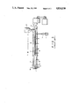
- FIGS. 1 to 3 are views for explaining an extruder used in a method of the present invention.
- FIGS. 4 and 5 are views for explaining an extruder used in a conventional method.
- a polyolefin according to the present invention is defined as a polyolefin or a polymer containing a polyolefin and is at least one polymer selected from the group consisting of high-pressure low-density polyethylene, medium/low-pressure high-density polyethylene, low-pressure low-density polyethylene, medium-density polyethylene, an ethylene- ⁇ -olefin copolymer, polypropylene, an ethylene-ethyl acrylate copolymer, an ethylene-vinyl acetate copolymer, an ethylene-propylene copolymer, an ethylene-propylene-diene terpolymer, an ethylene-butene copolymer, polymethylpentane-1, polybutene, chlorinated polyethylene, and an ethylene-vinyl acetate-chlorine terpolymer.
- An inorganic fire retardant according to the present invention is at least one fire retardant selected from the group consisting of antimony trioxide, aluminum hydroxide, magnesium hydroxide, zinc borate, red phosphorus, sodium antimonate, ammonium primary phosphate, ammonium secondary phosphate, ammonium bromide, ammonium borate, and ammonium sulfamate.
- Examples of an organic flow retardant according to the present invention are an alkyl phosphoric ester, a halogen acid-containing ester, an acidic phosphoric ester, a nitrogen-containing phosphorus compound, and a polymerizable phosphorus compound monomer.
- Examples of the alkyl phosphoric ester are trimethylphosphate and triethylphosphate.
- Examples of the halogen acid-containing ester are tris(chloroethyl)phosphate and tris(2,3-dibromopropyl)phosphate.
- halogen-based organic fire retardant examples include chlorinated paraffin, chlorinated polyolefin, brominated polyphenyldecabromodiphenyl ether, hexabromocyclododecane, perchloropentacyclodecane (Dechlorone Plus), and tetrabromobisphenol A.
- the inorganic filler used in the present invention is at least one material selected from the group consisting of all silicate minerals (e.g., baked clay, kaoline clay, an aluminum silicate glass powder, and a glass fiber), calcium carbonate, talk, and water-containing magnesium silicate.
- silicate minerals e.g., baked clay, kaoline clay, an aluminum silicate glass powder, and a glass fiber
- calcium carbonate talk
- water-containing magnesium silicate e.g., calcium carbonate, talk, and water-containing magnesium silicate.
- the unsaturated alkoxysilane used in the present invention is represented by general formula RR'SiY 2 wherein R is an olefinic unsaturated group having a valency of 1 and containing carbon, hydrogen and oxygen atoms.
- R is an olefinic unsaturated group having a valency of 1 and containing carbon, hydrogen and oxygen atoms.
- the unsaturated alkoxysilane are vinyl, allyl, butenyl, cyclohexenyl, cyclopentadienyl, cyclohexadienyl, CH 2 ⁇ C(CH 3 )COO(CH 2 ) 3 --, CH 2 ⁇ C(CH 3 )COOCH 2 CH 2 O(CH 2 ) 3 --, and CH 2 ⁇ C(CH 3 )COOCH 2 CH 2 OCH 2 CHCH 2 O(CH 2 ) 3 --.
- Y is a hydrolyzable organic group such as an alkoxy group (e.g., a methoxy group, an ethoxy group, and a butoxy group), an acyloxy group (e.g., a formyloxy group, an acetoxy group, an a propionoxy group), an oxymo group (e.g., --ON ⁇ C(CH 3 ) 2 , --ON ⁇ C(CH 3 )C 2 H 5 , and --ON ⁇ C(C 6 H 5 ) 2 , and a substituted amino group (e.g., an alkyl amino and aryl amino groups such as --NHCH 3 , --NHC 2 H 5 , and NH(C 6 H 5 ).
- an alkoxy group e.g., a methoxy group, an ethoxy group, and a butoxy group
- an acyloxy group e.g., a formyloxy group, an acetoxy group, an a propionoxy group
- R' is a hydrocarbon group having a valency of 1 and not containing an unsaturated aliphatic group and is exemplified by methyl, ethyl, propyl, tetradecyl, octadecyl, phenyl, benzyl or tryl.
- Group R' may be group Y.
- the unsaturated alkoxysilane is preferably represented by general formula RSiY3 (wherein R is a vinyl group).
- R is a vinyl group.
- examples of the unsaturated alkoxysilane are vinyl triethoxysilane and vinyl trimethoxysilane.
- the radical polymerization initiator is a compound which causes generation of radicals in polyolefin under reactive conditions. This compound has half-life of 6 minutes or less and preferably one minute or less at the reaction temperature.
- Examples of the best known and preferable free radical formation compound are organic peroxides and peresters (e.g., benzoyl peroxide, dichlorobenzoyl peroxide, dicumyl peroxide, di-tert-butyl peroxide, 2,5-dimethyl-2,5-di(peroxybenzoate)hexyne-3, 1,3-bis(t-butylperoxyisopropyl)benzene, lauroyl peroxide, tert-butyl peracetate, 2,5-dimethyl-2,5-di(t-butylperoxy)hexyne, 2,5-dimethyl-2,5-di(t-butylperoxy)hexane, and tert-butylperbenzoate) and azo compounds (e.g., azobisisobutylnitrile and dimethylazodiisobutylate).
- organic peroxides and peresters e.g., benzoyl
- the silanol condensation catalyst used in the present invention is metal salts of carboxylic acid and its examples are dibutyl tin dilaurylate, dibutyl tin diacetate, dibutyl tin dioctoate, stannous acetate, stannous caprylate, lead naphthenate, zinc caprylate, 2-ethyl ferrous caprylate, and cobalt naphthenate.
- the silanol condensation catalyst may also be an organic metal compound such as titanium ester or chelate (e.g., tetrabutyltitanate, tetranonyltitanate, bis(acetylacetonyl)-di-isopropyltitanate); an organic base (e.g., ethylamine, hexylamine, dibutylamine, and piperidine); and an acid (e.g., a mineral acid and fatty acid).
- titanium ester or chelate e.g., tetrabutyltitanate, tetranonyltitanate, bis(acetylacetonyl)-di-isopropyltitanate
- organic base e.g., ethylamine, hexylamine, dibutylamine, and piperidine
- an acid e.g., a mineral acid and fatty acid
- silanol condensation catalyst can be addd together with an unsaturated alkoxysilane and a radical formation agent.
- the silanol condensation catalyst may be coated on the surface of the extruded product or dispersed in water as an emulsion type.
- Various types of components such as an antioxidant, a metal inhibitor, an ultraviolet absorber, and a colorant may be used so as not to impair the effect of the present invention in the fabrication of an extruded product of a fire-retardant crosslinked polyolefin composition.
- a static mixer/stirrer as cooling equipment in a cooling zone is used or a means such as an extruder or a gear pump is used to stir and cool the molten resin composition to control its temperature.
- polyolefin pellets and a compound of a filler (e.g., a fire retardant) and a silanol condensation catalyst are supplied from a hopper of the extruder.
- An unsaturated alkoxysilane and a graft reaction agent e.g., an organic peroxide
- a cooling zone is provided between an extruder and a crosshead to set a uniform temperature of a molten resin composition and to cool the composition temperature to a desired temperature.
- the resin temperature is decreased below the critical temperature (i.e., 170° C. or less) at which bubbles are formed, thereby preparing an extruded product of a fire-retardant polyolefin composition.
- test compositions are as follows:
- the mixing rates of the components of the test composition are as is shown in the following table.
- the EEA pellets and the masterbatch are mixed in a predetermined mixing ratio.
- the unsaturated alkoxysilane and the organic peroxide are mixed to prepare a liquid mixture.
- the liquid mixture is injected by a pump into the extruder in accordance with the extrusion rate.
- the extrusion operation will be described in more detail with reference to the accompanying drawings.
- the polyolefin pellets and a compound (to be referred to as a masterbatch hereinafter) of the fire-retardnant and the silanol condensation catalyst were supplied from hopper 4 of extruder 3 into extruder cylinder 8.
- Mixture solution 1 of the unsaturated alkoxysilane and the organic peroxide was quantitatively supplied to cylinder 8 by injecting pump 2.
- Extruder 3 had a diameter of 55 mm and an L/D of 28.
- Supply zone F was set as 6 to 8D (where D is the diameter of the extruder), compression zone C was 7 to 8D, and metering zone M was 12 to 15D.
- Uniform kneading and metering of molten polyolefin were performed. Thereafter, the molten composition was extruded on the circumferential surface of conductor W driven by crosshead 6 mounted at the distal end of extruder 3 (FIG. 4). The extruded wire was exposed to moisture and crosslinked.
- the extruder comprised thermocouple 9 and heater 7. Temperature control device were performed to control the temperature of extruder 3 with a given temperature gradient.
- Screw 5 may be a fullflight screw or any other mixing screw may be used. However, in this example, a fluted mixing screw was used. 40-, 60-, and 80-mesh stainless steel nets were respectively inserted in the corresponding positions in breaker plate 10. The evaluation of the presence/absence of bubbles was performed as follows. A material extruded from the die port was extracted as a hollow pipe having a length of 30 to 40 mm. The hollow pipe was immediately dipped in a water tank. The cross section of the pipe was observed with an eye and a 10X magnifier.
- the material was concentrically extruded to obtain extruded products each having a thickness of 1.5 mm on a circular compression copper conductor having a diameter of 5.5 mm and a cross-sectional area of 22 mm 2 .
- the nipple had a diameter of 5.6 mm and the die had a diameter of 8.6 mm.
- the linear speed in terms of an extrusion rate was calculated to achieve a substantially constant cooling time.
- the bubbles were evaluated by cross sections of pipe- and wire-like extruded products.
- the gel fraction was the weight of an insoluble component after extraction in xylene at 120° C. for 24 hours.
- the heat deformation coefficient was measured on the basis of a JIS method when the extruded and crosslinked products were preheated at 120° C. for 30 minutes and loaded with 1.5 kg for 30 minutes.
- the heat deformation coefficients could be calculated by the following relation: ##EQU1##
- the outer appearance was evaluated with a naked eye for the outer surfaces of the extruded electric wires.
- a composition as in Comparative Example 1 was used, and cylinder 11 (having a diameter of 55 mm and an L/D of 9) was connected as a simple cooling zone to extruder 3 (see FIG. 5).
- the temperature profile of extruder 3 was set as follows:
- the temperature of the cylinder as the cooling zone was changed in the range of 65° C. to 160° C.
- the temperature profiles of the crosshead and the die were evaluated at 170° C. and in the temperature range of 100° to 130° C.
- the resuls are summarized in Table 1.
- the molten resin composition temperature was not sufficiently decreased.
- Static mixer/stirrer static mixer having an inner diameter of 38 mm and an L/D of 9
- a composition as in Comparative Example 1 was used.
- the temperature profile of extruder 3 was set as follows:
- the temperature of the static mixer was changed in the range of 65° C. to 160° C.
- the temperature profiles of the crosshesad and the die were evaluated at 170° C. and in the range of 100° to 130° C. The results are summarized in Table 2.
- the molten resin composition temperature can be low enough not to cause generation of bubbles (i.e., 170° C. or less) and the degree of crosslinking is satisfactory.
- Extruder 11 having a diameter of 55 mm and an L/D of 12 was connected as a cooling zone to extruder 3 (see FIG. 2).
- a composition as in Comparative Example 1 was used.
- the temperature profile of extruder 3 was set as follows:
- the temperature of extruder 11 was changed in the range of 65° C. to 160° C.
- the temperature profiles of the crosshead and the die were evaluated at 170° C. and 130° C. The results are summarized in Table 3. As is apparent from Table 3, the degree of crosslinking is satisfactory and bubbles are not formed in the temperature range of the cooling zone.
- a composition as in Comparative Example 1 was used. 100 cc/rev straight gear pump 11 was connected as a cooling zone to extruder 3 (see FIG. 3). Reference numeral 12 in FIG. 3 denotes gears.
- the temperature profile of extruder 3 was set as follows:
- the temperature of gear pump 11 was changed in the range of 65° C. to 160° C.
- the temperature profiles of the crosshead and the die were evaluated at 170° C. and in the range of 100° to 130° C. The results are summarized in Table 4.
- a rate of change in molten resin composition temperature is small. However, it is found conditions under which no bubbles are formed can be established by utilizing a cooling capacity (blowing and water cooling).
- Static mixer/stirrer static mixer having an inner diameter of 30 mm and an L/D of 9
- the temperature profile of extruder 3 was set as follows:
- the temperature of static mixer 11 was controlled in the range of 65° to 90° C.
- the temperature profiles of the crosshead and the die were controlled, as shown in Table 5. Results are shown in Table 5.
- An L-LDPE (low-pressure low-density polyethylene) based composition can also be used.
- the mixing ratio of the components such as silanol condensation catalyst is not limited to the level defined in Table 5.
- a subextruder or a gear group may be used together with the existing extruder.
Abstract
Description
______________________________________
Material      Content  Remarks
______________________________________
EEA (Ethylene-Ethyl
              100 PHR  Nihon Unicar
acrylate copolymer)    M.I. = 1.5, EA content =
                       15%
Metal Hydrate 250      Magnesium hydroxide
Fire Retardant
              70       Phosphorus
Antioxidant   10       Irganox
Silanol Condensation
              0.5      Dibutyl-tin-di-
Catalyst               laurylate
Total         430.5
______________________________________
______________________________________
Material      Content  Remarks
______________________________________
EEA           70 PHR   Nihon Unicar
                       M.I. = 1.5, EA content =
                       15%
Fire Retardant-
              30       the above table
catalyst Master-
batch
Unsaturated Alkoxy-
              2        Vinyltrimethoxysilane
silane
Organic Peroxide
              0.15     Dicumylperoxide
Total         102.15
______________________________________
______________________________________
Material            Content
______________________________________
EEA                   100 PHR
Metal Hydrate       22.6
Fire retardant      6.4
Antioxidant         0.9
Silanol Condensation Catalyst
                    0.04
Unsaturated Alkoxysilane
                    2.6
Organic Peroxide    0.19
Total               132.73 PHR
______________________________________
______________________________________
                                Crosshead
                                        Die
F      C                 M      C.H.    D
______________________________________
160° C.
       180° C.
                200° C.
                         200° C.
                                200° C.
                                        200° C.
______________________________________
______________________________________
                                Crosshead
                                        Die
F      C                 M      C.H.    D
______________________________________
120° C.
       140° C.
                160° C.
                         160° C.
                                160° C.
                                        160° C.
______________________________________
______________________________________
F     C                  M       C.H.  D
______________________________________
160° C.
      180° C.
                 200° C.
                         200° C.
                                 160° C.
                                       160° C.
______________________________________
                                  TABLE 1
__________________________________________________________________________
           Comparative Example 1
                          Comparative Example 2
__________________________________________________________________________
Extruder
Temperature
F Zone    160° C.
              160° C.
                  120° C.
                      120° C.
                          160° C.
                                 160° C.
                                        160° C.
                                               160° C.
After C Zone
          180° C.
              180° C.
                  140° C.
                      140° C.
                          180° C.
                                 180° C.
                                        180° C.
                                               180° C.
Before C Zone
          200° C.
              200° C.
                  160° C.
                      160° C.
                          200° C.
                                 200° C.
                                        200° C.
                                               200° C.
M zone    200° C.
              200° C.
                  160° C.
                      160° C.
                          200° C.
                                 200° C.
                                        200° C.
                                               200° C.
Cooling Zone
Structure None
              None
                  None
                      None
                          Cylinder
                                 55φL/D = 9
                                        55φL/D = 9
                                               55φL/D = 9
                          55φL/D = 9
Temperature               65° C.
                                 65° C.
                                        160° C.
                                               160° C.
Crosshead 200° C.
              200° C.
                  140° C.
                      140° C.
                          170° C.
                                 170°  C.
                                        170° C.
                                               170° C.
Temperature
Die Temperature
          200° C.
              200° C.
                  140° C.
                      140° C.
                          170° C.
                                 170° C.
                                        170° C.
                                               170° C.
Screw Speed
          20 rpm
              40 rpm
                  20 rpm
                      40 rpm
                          20 rpm 40 rpm 20 rpm 40 rpm
Molten Resin
          186° C.
              194° C.
                  158° C.
                      165° C.
                          176° C.
                                 183° C.
                                        180° C.
                                               186° C.
Temperature
Bubble    Many
              Many
                  None
                      None
                          Many   Many   Many   Many
Gel Fraction
          70% 72% 48% 47% 65%    70%    69%    72%
Heat Deformation
          19% 15% 43% 50% 22%    16%    20%    13%
Coefficient
Outer Appearance
          Good
              Good
                  Good
                      Good
                          Good   Good   Good   Good
__________________________________________________________________________
______________________________________
F        C                 M
______________________________________
160° C.
         180° C.
                       200° C.
                               200° C.
______________________________________
TABLE 2
__________________________________________________________________________
Example 1
__________________________________________________________________________
Extruder
Temperature
F Zone 160° C.
160° C.
160° C.
160° C.
160° C.
160° C.
160° C.
After C Zone
180° C.
180° C.
180° C.
180° C.
180° C.
180° C.
180° C.
Before C Zone
200° C.
200° C.
200° C.
200° C.
200° C.
200° C.
200° C.
M zone 200° C.
200° C.
200° C.
200° C.
200° C.
200° C.
200° C.
Cooling Zone
Structure Static Static Static Static Static Static Static
mixer/stirrer
mixer/stirrer
mixer/stirrer
mixer/stirrer
mixer/stirrer
mixer/stirrer
mixer/stirrer
38φL/D = 9
38φL/D = 9
38φL/D = 9
38φL/D = 9
38φL/D = 9
38φL/D
38φL/D = 9
Six elements
Six elements
Six elements
Six elements
Six elements
Six elements
Six elements
Temperature
160° C.
160° C.
140° C.
140° C.
120° C.
120° C.
120° C.
Crosshead 170° C.
170° C.
170° C.
170° C.
170° C.
170° C.
130° C.
Temperature
Die Temperature
170° C.
170° C.
170° C.
170° C.
170° C.
170° C.
130° C.
Screw Speed
20 rpm 40 rpm 20 rpm 40 rpm 20 rpm 40 rpm 20 rpm
Molten Resin
173° C.
183° C.
168° C.
176° C.
167° C.
177° C.
146° C.
Temperature
Bubble Little Many None Little None Little None
Gel Fraction
66% 69% 70% 73% 67% 68% 70%
Heat Deformation
24% 20% 15% 14% 20% 22% 19%
Coefficient
Outer Appearance
Good Good Good Good Good Good Good
Extruder
Temperature
F Zone 160° C.
160° C.
160° C.
160° C.
160° C.
160° C.
160° C.
After C Zone
180° C.
180° C.
180° C.
180° C.
180° C.
180° C.
180° C.
Before C Zone
200° C.
200° C.
200° C.
200° C.
200° C.
200° C.
200° C.
M Zone 200° C.
200° C.
200° C.
200° C.
200° C.
200° C.
200° C.
Cooling Zone
Structure Static Static Static Static Static Static Static
mixer/stirrer
mixer/stirrer
mixer/stirrer
mixer/stirrer
mixer/stirrer
mixer/stirrer
mixer/stirrer
38φL/D = 9
38φL/D = 9
38φL/D = 9
38φL/D = 9
38φL/D = 9
38φL/D
38φL/D = 9
Six elements
Six elements
Six elements
Six elements
Six elements
Six elements
Six elements
Temperature
120° C.
100° C.
100° C.
80° C.
80° C.
65° C.
65° C.
Crosshead 130° C.
130° C.
130° C.
120° C.
120° C.
100° C.
100° C.
Temperature
Die Temperature
130° C.
130° C.
130° C.
120° C.
120° C.
100° C.
100° C.
Screw Speed
40 rpm 20 rpm 40 rpm 20 rpm 40 rpm 20 rpm 40 rpm
Molten Resin
169° C.
149° C.
170° C.
137° C.
168° C.
128° C.
164° C.
Temperature
Bubble None None None None None None None
Gel Fraction
65% 58% 65% 74% 78% 78% 72%
Heat Deformation
25% 29% 26% 15% 19% 15% 14%
Coefficient
Outer Appearance
Good Good Good Good Good Good Good
__________________________________________________________________________
______________________________________
F        C                 M
______________________________________
160° C.
         180° C.
                       200° C.
                               200° C.
______________________________________
                                  TABLE 3
__________________________________________________________________________
           Example 2
__________________________________________________________________________
Extruder
Temperature
F Zone    160° C.
                  160° C.
                          160° C.
                                  160° C.
                                          160° C.
                                                  160° C.
After C Zone
          180° C.
                  180° C.
                          180° C.
                                  180° C.
                                          180° C.
                                                  180° C.
Before C Zone
          200° C.
                  200° C.
                          200° C.
                                  200° C.
                                          200° C.
                                                  200° C.
M zone    200° C.
                  200° C.
                          200° C.
                                  200° C.
                                          200° C.
                                                  200° C.
Cooling Zone
Structure 55φL/D = 12
                  55φL/D = 12
                          55φL/D = 12
                                  55φL/D = 12
                                          55φL/D = 12
                                                  55φ L/D = 12
          extruder
                  extruder
                          extruder
                                  extruder
                                          extruder
                                                  extruder
Temperature
          160° C.
                  160° C.
                          120° C.
                                  120° C.
                                          65° C.
                                                  65° C.
Crosshead 170° C.
                  170° C.
                          170° C.
                                  170° C.
                                          170° C.
                                                  170° C.
Temperature
Die Temperature
          170° C.
                  170° C.
                          170° C.
                                  170° C.
                                          170° C.
                                                  170°  C.
First and Second
          20 rpm  40 rpm  20 rpm  40 rpm  20 rpm  40 rpm
Extruder Screw
Speeds
Molten Resin
          178° C.
                  186° C.
                          142° C.
                                  160° C.
Temperature
Bubble    Many    Many    None    None    Large motor load
                                          in second extruder
Gel Fraction
          71%     70%     70%     66%
Heat Deformation
          20%     18%     15%     24%
Coefficient
Outer Appearance
          Good    Good    Good    Good
Extruder
Temperature
F Zone    160° C.
                  160° C.
                          160° C.
                                  160° C.
                                          160° C.
                                                  160° C.
After C Zone
          180° C.
                  180° C.
                          180° C.
                                  180° C.
                                          180° C.
                                                  180° C.
Before C Zone
          200° C.
                  200° C.
                          200° C.
                                  200° C.
                                          200° C.
                                                  200° C.
M zone    200° C.
                  200° C.
                          200° C.
                                  200° C.
                                          200° C.
                                                  200° C.
Cooling Zone
Structure 55φL/D = 12
                  55φL/D = 12
                          55φL/D = 12
                                  55φL/D = 12
                                          55φL/D = 12
                                                  55φL/D =  12
          extruder
                  extruder
                          extruder
                                  extruder
                                          extruder
                                                  extruder
Temperature
          160° C.
                  160° C.
                          120° C.
                                  120° C.
                                          65° C.
                                                  65° C.
Crosshead 130° C.
                  130° C.
                          130° C.
                                  130° C.
                                          130° C.
                                                  130° C.
Temperature
Die Temperature
          130° C.
                  130° C.
                          130° C.
                                  130° C.
                                          130° C.
                                                  130° C.
First and Second
          20 rpm  40 rpm  20 rpm  40 rpm  20 rpm  40 rpm
Extruder Screw
Speeds
Molten Resin
          176° C.
                  182° C.
                          135° C.
                                  146° C.
Temperature
Bubble    Many    Many    None    None    Large motor load
                                          in second extruder
Gel Fraction
          70%     72%     68%     65%
Heat Deformation
          17%     15%     23%     20%
Coefficient
Outer Appearance
          Good    Good    Good    Good
__________________________________________________________________________
______________________________________
F        C                 M
______________________________________
160° C.
         180° C.
                       200° C.
                               200° C.
______________________________________
                                  TABLE 4
__________________________________________________________________________
           Example 3
__________________________________________________________________________
Extruder
Temperature
F Zone    160° C.
                160° C.
                      160° C.
                            160° C.
                                  160° C.
                                        160° C.
After C Zone
          180° C.
                180° C.
                      180° C.
                            180° C.
                                  180° C.
                                        180° C.
Before C Zone
          200° C.
                200° C.
                      200° C.
                            200° C.
                                  200° C.
                                        200° C.
M zone    200° C.
                200° C.
                      200° C.
                            200° C.
                                  200° C.
                                        200° C.
Cooling Zone
Structure 10 cc/rev
                10 cc/rev
                      10 cc/rev
                            10 cc/rev
                                  10 cc/rev
                                        10 cc/rev
          straight
                straight
                      straight
                            straight
                                  straight
                                        straight
          gear pump
                gear pump
                      gear pump
                            gear pump
                                  gear pump
                                        gear pump
Temperature
          160° C.
                160° C.
                      120° C.
                            120° C.
                                  65° C.
                                        65° C.
Crosshead 170° C.
                170° C.
                      170° C.
                            170° C.
                                  170° C.
                                        170° C.
Temperature
Die Temperature
          170° C.
                170° C.
                      170° C.
                            170° C.
                                  170° C.
                                        170° C.
Screw Speed
          20 rpm
                40 rpm
                      20 rpm
                            40 rpm
                                  20 rpm
                                        40 rpm
Molten Resin
          175° C.
                186° C.
                      172° C.
                            183° C.
                                  166° C.
                                        179° C.
Temperature
Bubble    Many  Many  Little
                            Many  None  Many
Gel Fraction
          71%   70%   65%   68%   62%   65%
Heat Deformation
          19%   24%   22%   25%   24%   18%
Coefficient
Outer Appearance
          Good  Good  Good  Good  Good  Good
Extruder
Temperature
F Zone    160° C.
                160° C.
                      160° C.
                            160° C.
                                  160° C
                                        160° C.
After C Zone
          180° C.
                180° C.
                      180° C.
                            180° C.
                                  180° C.
                                        180° C.
Before C Zone
          200° C.
                200° C.
                      200° C.
                            200° C.
                                  200° C.
                                        200° C.
M zone    200° C.
                200° C.
                      200° C.
                            200° C.
                                  200° C.
                                        200° C.
Cooling Zone
Structure 10 cc/rev
                10 cc/rev
                      10 cc/rev
                            10 cc/rev
                                  10 cc/rev
                                        10 cc/rev
          straight
                straight
                      straight
                            straight
                                  straight
                                        straight
          gear pump
                gear pump
                      gear pump
                            gear pump
                                  gear pump
                                        gear pump
Temperature
          160° C.
                160° C.
                      120° C.
                            120° C.
                                  65° C.
                                        65° C.
Crosshead 130° C.
                130° C.
                      130° C.
                            130° C.
                                  130° C.
                                        130° C.
Temperature
Die Temperature
          130° C.
                130° C.
                      130° C.
                            130° C.
                                  130° C.
                                        130° C.
Screw Speed
          20 rpm
                40 rpm
                      20 rpm
                            40 rpm
                                  20 rpm
                                        40 rpm
Molten Resin
          173° C.
                180° C.
                      166° C.
                            176° C.
                                  162° C.
                                        170° C.
Temperature
Bubble    Little
                Many  None  Many  None  Little
Gel Fraction
          67%   72%   64%   66%   70%   69%
Heat Deformation
          20%   17%   20%   22%   19%   17%
Coefficient
Outer Appearance
          Good  Good  Good  Good  Good  Good
__________________________________________________________________________
______________________________________
F        C                 M
______________________________________
160° C.
         180° C.
                       200° C.
                               200° C.
______________________________________
                                  TABLE 5
__________________________________________________________________________
           Example 4
__________________________________________________________________________
EEA (EA cont. 15%)
           100 PHR                    70 PHR
                                           70 PHR
                                                70 PHR
                                                     100
                                                          100 PHR
High Pressure   100
Low-Density     PHR
Polyethylene
Low-Pressure        100               30"  30"  30"
High-Density        PHR
Polyethylene
Low-Pressure            100
Low-Density             PHR
Polyethylene
EVA (VA cont. 18%)          100 PHR
EPDM                             100 PHR
Magnesium  50"  50" 50" 50" 50"  50"  15"  100" 200"
Hydroxide
Red Phosphorus
           7"   7"  7"  7"  7"   7"   7"   7"   7"
Antimony Trioxide                                    30"
Decabromodiphenyl                                    60"
Ether
Calcium Carbonate                                         50"
Unsaturated
           1.8" 1.8"
                    1.8"
                        1.8"
                            1.8" 1.8" 1.8" 1.8" 1.8" 1.8" 1.8"
Alkoxysilane
Organic Peroxide
           0.13"
                0.13"
                    0.13"
                        0.13"
                            0.13"
                                 0.13"
                                      0.13"
                                           0.13"
                                                0.13"
                                                     0.13"
                                                          0.13"
Silanol Condensa-
           0.05"
                0.05"
                    0.05"
                        0.05"
                            0.05"
                                 0.05"
                                      0.05"
                                           0.05"
                                                0.05"
                                                     0.05"
                                                          0.05"
tion Catalyst
Antioxidant
           2"   2"  2"  2"  2"   2"   2"   2"   2"   2"   2"
Extruder
Temperature
F Zone     160° C.
                160° C.
                    160° C.
                        160° C.
                            160° C.
                                 160° C.
                                      160° C.
                                           160° C.
                                                160° C.
                                                     160° C.
                                                          160° C.
After C Zone
           180° C.
                180° C.
                    180° C.
                        180° C.
                            180° C.
                                 180° C.
                                      180° C.
                                           180° C.
                                                180° C.
                                                     180° C.
                                                          180° C.
Before C Zone
           200° C.
                200° C.
                    200° C.
                        200° C.
                            200° C.
                                 200° C.
                                      200° C.
                                           200° C.
                                                200° C.
                                                     200° C.
                                                          200° C.
M Zone     200° C.
                200° C.
                    200° C.
                        200° C.
                            200° C.
                                 200° C.
                                      200° C.
                                           200° C.
                                                200° C.
                                                     200° C.
                                                          200° C.
Static Mixer
           65° C.
                70° C.
                    80° C.
                        80° C.
                            65° C.
                                 65° C.
                                      80° C.
                                           80° C.
                                                80° C.
                                                     65° C.
                                                          65° C.
Crosshead  130° C.
                130° C.
                    130° C.
                        130° C.
                            130° C.
                                 130° C.
                                      130° C.
                                           130° C.
                                                130° C.
                                                     130° C.
                                                          130° C.
Temperature
Die Temperature
           130° C.
                130° C.
                    130° C.
                        130° C.
                            130° C.
                                 130° C.
                                      130° C.
                                           130° C.
                                                130° C.
                                                     130° C.
                                                          130° C.
Screw Speed
           20 rpm
                20 rpm
                    20 rpm
                        20 rpm
                            20 rpm
                                 20 rpm
                                      20 rpm
                                           20 rpm
                                                20 rpm
                                                     20
                                                          20 rpm
Molten Resin
           152° C.
                163 166 165 150  147  158  166  167  156  153
Temperature
Bubble     None None
                    None
                        None
                            None None None None None None None
Gel Fraction
           62%  60% 62% 65% 62%  62%  60%  63%  63%  65%  65%
Heat Deformation
           25%  25% 19% 20% 32%  --   24%  20%  23%  25%  26%
Coefficient
Outer Appearance
           Good Good
                    Good
                        Good
                            Good Good Good Good Rela-
                                                     Good Good
                                                tively
                                                bad
__________________________________________________________________________
Claims (13)
RR'SiY.sub.2
Applications Claiming Priority (2)
| Application Number | Priority Date | Filing Date | Title |
|---|---|---|---|
| JP61-146133 | 1986-06-24 | ||
| JP61146133A JPH0698662B2 (en) | 1986-06-24 | 1986-06-24 | Process for producing extruded article of crosslinked polyolefin composition |
Publications (1)
| Publication Number | Publication Date |
|---|---|
| US4814130A true US4814130A (en) | 1989-03-21 |
Family
ID=15400887
Family Applications (1)
| Application Number | Title | Priority Date | Filing Date |
|---|---|---|---|
| US07/065,268 Expired - Lifetime US4814130A (en) | 1986-06-24 | 1987-06-22 | Method of manufacturing extruded product of fire-retardant crosslinked polyolefin composition |
Country Status (6)
| Country | Link |
|---|---|
| US (1) | US4814130A (en) |
| EP (1) | EP0251161B1 (en) |
| JP (1) | JPH0698662B2 (en) |
| KR (1) | KR930005822B1 (en) |
| BR (1) | BR8703194A (en) |
| DE (1) | DE3784788T2 (en) |
Cited By (14)
| Publication number | Priority date | Publication date | Assignee | Title |
|---|---|---|---|---|
| WO1991016189A1 (en) * | 1990-04-12 | 1991-10-31 | Exxon Chemical Patents Inc. | Polymer grafting process, apparatus and products obtained therewith |
| US5075061A (en) * | 1989-06-15 | 1991-12-24 | Bicc Public Limited Company | Manufacture of extruded products |
| US5378539A (en) * | 1992-03-17 | 1995-01-03 | E. I. Du Pont De Nemours And Company | Cross-linked melt processible fire-retardant ethylene polymer compositions |
| EP0676632A2 (en) * | 1994-04-04 | 1995-10-11 | Sumitomo Electric Industries, Ltd. | Method and apparatus for detecting foreign objects in resin |
| US5514312A (en) * | 1990-06-18 | 1996-05-07 | Coflexip | Process for manufacturing a flexible tubular conduit having a jacket made of crosslinked polyethylene |
| US6107413A (en) * | 1995-12-27 | 2000-08-22 | Sumitomo Bakelite Company Limited | Process for producing flame-retardant, silane-crosslinked polyolefin |
| US20060108706A1 (en) * | 2002-07-11 | 2006-05-25 | Maurizio Galimberti | Process and apparatus for continuously producing an elatomeric composition |
| US20110003942A1 (en) * | 2008-02-29 | 2011-01-06 | Sumitomo Chemical Company, Limited | Process for producing modified olefin polymer |
| KR101161330B1 (en) | 2012-03-14 | 2012-07-02 | 주식회사 티앤비우드 | Manufaturing method of incombustible synthetic resin panel |
| CN102975378A (en) * | 2012-12-10 | 2013-03-20 | 南充市富康塑胶制品厂 | Flame retardant wire-pulling pipe |
| US20140227518A1 (en) * | 2011-06-08 | 2014-08-14 | Riken Technos Corporation | Process for producing electrical wire molded body |
| US10083776B2 (en) | 2013-09-27 | 2018-09-25 | Furukawa Electric Co., Ltd. | Heat-resistant silane crosslinked resin molded body and method of producing the same, heat-resistant silane crosslinkable resin composition and method of producing the same, silane master batch, and heat-resistant product using heat-resistant silane crosslinked resin molded body |
| US20180286535A1 (en) * | 2017-03-30 | 2018-10-04 | Ls Cable & System Ltd. | Halogen-free flame-retardant polyolefin insulation composition and cable having an insulating layer formed from the same |
| US10307952B2 (en) * | 2015-09-07 | 2019-06-04 | Canon Kabushiki Kaisha | Cylindrical extruding die and method for producing seamless tube |
Families Citing this family (5)
| Publication number | Priority date | Publication date | Assignee | Title |
|---|---|---|---|---|
| JPH01255628A (en) * | 1988-04-05 | 1989-10-12 | Kawasaki Steel Corp | Continuous bright annealing method for wide thin band steel and wide band foil and horizontal continuous bright annealing furnace |
| EP0771827B1 (en) * | 1995-10-30 | 2001-05-23 | Sekisui Kagaku Kogyo Kabushiki Kaisha | Process for producing silane-modified polyolefins and extruder apparatus therefor |
| JP2008280517A (en) * | 2007-04-12 | 2008-11-20 | Hitachi Cable Ltd | Method of manufacturing non-halogen flame-retardant thermoplastic composition |
| FR2994434B1 (en) * | 2012-08-09 | 2015-09-04 | Nexans | PROCESS FOR PREPARING A CHARGED POLYMERIC COMPOSITION FOR RETICULATING |
| WO2018212406A1 (en) * | 2017-05-19 | 2018-11-22 | 김복성 | Multi-speed transmission of motor for transportation means |
Citations (11)
| Publication number | Priority date | Publication date | Assignee | Title |
|---|---|---|---|---|
| JPS538668A (en) * | 1976-07-13 | 1978-01-26 | Denki Kagaku Kogyo Kk | Extruder for thermoplastic resin foam |
| US4117195A (en) * | 1974-12-06 | 1978-09-26 | Bicc Limited | Manufacture of extruded products |
| US4117063A (en) * | 1974-12-12 | 1978-09-26 | Kabel-Und Metallwerke Gutehoffnungshutte Ag. | Processing a graft polymer or elastomer |
| US4228255A (en) * | 1976-12-14 | 1980-10-14 | The Fujikura Cable Works Ltd. | Method for producing crosslinked polyethylenes |
| JPS5784828A (en) * | 1980-11-18 | 1982-05-27 | Furukawa Electric Co Ltd:The | Manufacture of plastic foam |
| US4444948A (en) * | 1979-04-03 | 1984-04-24 | Maillefer, S.A. | Manufacture of insulated electric conductors |
| US4489029A (en) * | 1983-06-01 | 1984-12-18 | Union Carbide Corporation | Compositions based on alkylene-alkyl acrylate copolymers and silanol condensation catalysts; and the use thereof in the production of covered wires and cables |
| US4514539A (en) * | 1983-05-05 | 1985-04-30 | Reichhold Chemicals, Inc. | Stain resistant polymeric insulating compositions |
| US4564349A (en) * | 1983-06-01 | 1986-01-14 | Union Carbide Corporation | Extruder assembly for extruding water-curable silane modified polymers |
| EP0179755A2 (en) * | 1984-10-22 | 1986-04-30 | Rosendahl Maschinen Gesellschaft m.b.H. | Method and apparatus for the manufacture of a cross-linked extruded or injection-moulded article |
| US4595546A (en) * | 1983-11-14 | 1986-06-17 | Crompton & Knowles Corporation | Manufacture of elongated extruded cross-linked products |
Family Cites Families (5)
| Publication number | Priority date | Publication date | Assignee | Title |
|---|---|---|---|---|
| CH618450A5 (en) * | 1974-03-08 | 1980-07-31 | Kabel Metallwerke Ghh | Process for the crosslinking of thermoplastic or elastomeric base material by grafting silane or a silane compound onto the base material in the presence of water |
| JPS5365347A (en) * | 1976-11-24 | 1978-06-10 | Sumitomo Bakelite Co Ltd | Flame betardant p olyolefin composition |
| US4420291A (en) * | 1979-01-05 | 1983-12-13 | Maryland Cup Corporation | Dynamic cooler apparatus for molten thermoplastic material |
| JPS6052926B2 (en) * | 1981-05-18 | 1985-11-22 | 積水化成品工業株式会社 | Thermoplastic resin foam manufacturing method and device |
| CH644058A5 (en) * | 1981-12-07 | 1984-07-13 | Maillefer Sa | Extruder with screw for plastics |
-
1986
- 1986-06-24 JP JP61146133A patent/JPH0698662B2/en not_active Expired - Lifetime
-
1987
- 1987-06-22 US US07/065,268 patent/US4814130A/en not_active Expired - Lifetime
- 1987-06-23 KR KR1019870006386A patent/KR930005822B1/en not_active IP Right Cessation
- 1987-06-24 BR BR8703194A patent/BR8703194A/en not_active IP Right Cessation
- 1987-06-24 DE DE8787109034T patent/DE3784788T2/en not_active Expired - Fee Related
- 1987-06-24 EP EP87109034A patent/EP0251161B1/en not_active Expired - Lifetime
Patent Citations (13)
| Publication number | Priority date | Publication date | Assignee | Title |
|---|---|---|---|---|
| US4117195B1 (en) * | 1974-12-06 | 1982-09-21 | ||
| US4117195A (en) * | 1974-12-06 | 1978-09-26 | Bicc Limited | Manufacture of extruded products |
| US4117063A (en) * | 1974-12-12 | 1978-09-26 | Kabel-Und Metallwerke Gutehoffnungshutte Ag. | Processing a graft polymer or elastomer |
| JPS538668A (en) * | 1976-07-13 | 1978-01-26 | Denki Kagaku Kogyo Kk | Extruder for thermoplastic resin foam |
| US4228255A (en) * | 1976-12-14 | 1980-10-14 | The Fujikura Cable Works Ltd. | Method for producing crosslinked polyethylenes |
| US4444948A (en) * | 1979-04-03 | 1984-04-24 | Maillefer, S.A. | Manufacture of insulated electric conductors |
| JPS5784828A (en) * | 1980-11-18 | 1982-05-27 | Furukawa Electric Co Ltd:The | Manufacture of plastic foam |
| US4514539A (en) * | 1983-05-05 | 1985-04-30 | Reichhold Chemicals, Inc. | Stain resistant polymeric insulating compositions |
| US4489029A (en) * | 1983-06-01 | 1984-12-18 | Union Carbide Corporation | Compositions based on alkylene-alkyl acrylate copolymers and silanol condensation catalysts; and the use thereof in the production of covered wires and cables |
| US4564349A (en) * | 1983-06-01 | 1986-01-14 | Union Carbide Corporation | Extruder assembly for extruding water-curable silane modified polymers |
| US4595546A (en) * | 1983-11-14 | 1986-06-17 | Crompton & Knowles Corporation | Manufacture of elongated extruded cross-linked products |
| EP0179755A2 (en) * | 1984-10-22 | 1986-04-30 | Rosendahl Maschinen Gesellschaft m.b.H. | Method and apparatus for the manufacture of a cross-linked extruded or injection-moulded article |
| US4716000A (en) * | 1984-10-22 | 1987-12-29 | Rosendahl Maschinen Gesellschaft M.B.H. | Process and apparatus for the production of a cross-linked, extruded or sprayed product |
Cited By (19)
| Publication number | Priority date | Publication date | Assignee | Title |
|---|---|---|---|---|
| US5075061A (en) * | 1989-06-15 | 1991-12-24 | Bicc Public Limited Company | Manufacture of extruded products |
| WO1991016189A1 (en) * | 1990-04-12 | 1991-10-31 | Exxon Chemical Patents Inc. | Polymer grafting process, apparatus and products obtained therewith |
| US5514312A (en) * | 1990-06-18 | 1996-05-07 | Coflexip | Process for manufacturing a flexible tubular conduit having a jacket made of crosslinked polyethylene |
| US5378539A (en) * | 1992-03-17 | 1995-01-03 | E. I. Du Pont De Nemours And Company | Cross-linked melt processible fire-retardant ethylene polymer compositions |
| EP0676632A2 (en) * | 1994-04-04 | 1995-10-11 | Sumitomo Electric Industries, Ltd. | Method and apparatus for detecting foreign objects in resin |
| EP0676632B1 (en) * | 1994-04-04 | 1998-09-23 | Sumitomo Electric Industries, Ltd. | Device for detecting foreign objects in resin |
| US6107413A (en) * | 1995-12-27 | 2000-08-22 | Sumitomo Bakelite Company Limited | Process for producing flame-retardant, silane-crosslinked polyolefin |
| US8236215B2 (en) * | 2002-07-11 | 2012-08-07 | Pirelli Pneumatici S.P.A. | Process and apparatus for continuously producing an elastomeric composition |
| US20060108706A1 (en) * | 2002-07-11 | 2006-05-25 | Maurizio Galimberti | Process and apparatus for continuously producing an elatomeric composition |
| US20110003942A1 (en) * | 2008-02-29 | 2011-01-06 | Sumitomo Chemical Company, Limited | Process for producing modified olefin polymer |
| US20140227518A1 (en) * | 2011-06-08 | 2014-08-14 | Riken Technos Corporation | Process for producing electrical wire molded body |
| US10559407B2 (en) * | 2011-06-08 | 2020-02-11 | Riken Technos Corporation | Process for producing electrical wire molded body |
| KR101161330B1 (en) | 2012-03-14 | 2012-07-02 | 주식회사 티앤비우드 | Manufaturing method of incombustible synthetic resin panel |
| CN102975378A (en) * | 2012-12-10 | 2013-03-20 | 南充市富康塑胶制品厂 | Flame retardant wire-pulling pipe |
| US10083776B2 (en) | 2013-09-27 | 2018-09-25 | Furukawa Electric Co., Ltd. | Heat-resistant silane crosslinked resin molded body and method of producing the same, heat-resistant silane crosslinkable resin composition and method of producing the same, silane master batch, and heat-resistant product using heat-resistant silane crosslinked resin molded body |
| US10304584B2 (en) | 2013-09-27 | 2019-05-28 | Furukawa Electric Co., Ltd. | Heat-resistant silane crosslinked resin molded body and method of producing the same, heat-resistant silane crosslinkable resin composition and method of producing the same, silane master batch, and heat-resistant product using heat-resistant silane crosslinked resin molded body |
| US10307952B2 (en) * | 2015-09-07 | 2019-06-04 | Canon Kabushiki Kaisha | Cylindrical extruding die and method for producing seamless tube |
| US20180286535A1 (en) * | 2017-03-30 | 2018-10-04 | Ls Cable & System Ltd. | Halogen-free flame-retardant polyolefin insulation composition and cable having an insulating layer formed from the same |
| US10497491B2 (en) * | 2017-03-30 | 2019-12-03 | Ls Cable & System Ltd. | Halogen-free flame-retardant polyolefin insulation composition and cable having an insulating layer formed from the same |
Also Published As
| Publication number | Publication date |
|---|---|
| DE3784788D1 (en) | 1993-04-22 |
| EP0251161A3 (en) | 1989-11-15 |
| KR930005822B1 (en) | 1993-06-25 |
| JPS633931A (en) | 1988-01-08 |
| EP0251161B1 (en) | 1993-03-17 |
| JPH0698662B2 (en) | 1994-12-07 |
| EP0251161A2 (en) | 1988-01-07 |
| KR880000210A (en) | 1988-03-24 |
| BR8703194A (en) | 1988-03-08 |
| DE3784788T2 (en) | 1993-09-02 |
Similar Documents
| Publication | Publication Date | Title |
|---|---|---|
| US4814130A (en) | Method of manufacturing extruded product of fire-retardant crosslinked polyolefin composition | |
| US4228255A (en) | Method for producing crosslinked polyethylenes | |
| US7241840B2 (en) | Process for crosslinking thermoplastic polymers with silanes employing peroxide blends and the resulting crosslinked thermoplastic polymers | |
| EP0163865B1 (en) | One-extrusion method for making a shaped crosslinked polymeric product | |
| US6528585B1 (en) | Cross-linkable polymers, method for the production thereof, and shaped bodies made of cross-linked polymers | |
| EP0426073B1 (en) | Solid feeding of silane crosslinking agents into extruder | |
| US5153382A (en) | Extrusion of thermoplastic copolymers | |
| US3795646A (en) | Cross-linking polyethylene compositions with silicone additive | |
| US3646155A (en) | Cross-linking of a polyolefin with a silane | |
| EP0004034B1 (en) | Method of crosslinking poly-alpha-olefin series resins | |
| US4117063A (en) | Processing a graft polymer or elastomer | |
| US4136132A (en) | Manufacture of extruded products | |
| JPH06293846A (en) | Production of article from blend of polyolefin with polymer containing reactive additive | |
| US4015058A (en) | Composition with dicumyl peroxide and process for avoiding scorching of ethylene polymer composition | |
| US20030132017A1 (en) | Method of manufacturing a cable sheath by extruding and cross-linking a composition based on silane-grafted polymer, and a cable including a sheath obtained by the method | |
| JPH06136066A (en) | Production of silane-grafted resin composition and production of molded article of silane-cross-linked resin composition | |
| CN1062284C (en) | Preparation of silane cross-linking polyethylene as electric cable material | |
| KR101677495B1 (en) | Environmental flexible Polyamide compound | |
| KR0138403B1 (en) | Method for preparing silane-crosslinked polyolefin composition for electric wire | |
| GB2201677A (en) | Process for producing a shaped, extruded product from a crosslinkable polymeric composition | |
| EP0235439A1 (en) | Electrically conductive polymers and their production | |
| JPS63221026A (en) | Manufacture of extrusion molded object of silane crosslinked polyolefin | |
| CA1088717A (en) | Processing a graft polymer or elastomer | |
| JPH058279A (en) | Preparation of polyethylene foam | |
| IE960123A1 (en) | Method of manufacturing cross-linked polyethylene |
Legal Events
| Date | Code | Title | Description |
|---|---|---|---|
| AS | Assignment |
Owner name: FURUKAWA ELECTRIC CO., LTD., 6-1, 2-CHOME, MARUNOU Free format text: ASSIGNMENT OF ASSIGNORS INTEREST.;ASSIGNORS:SHIROMATSU, EIJI;OHTANI, KENICHI;REEL/FRAME:004732/0422 Effective date: 19870616 |
|
| FEPP | Fee payment procedure |
Free format text: PAYOR NUMBER ASSIGNED (ORIGINAL EVENT CODE: ASPN); ENTITY STATUS OF PATENT OWNER: LARGE ENTITY |
|
| STCF | Information on status: patent grant |
Free format text: PATENTED CASE |
|
| FEPP | Fee payment procedure |
Free format text: PAYOR NUMBER ASSIGNED (ORIGINAL EVENT CODE: ASPN); ENTITY STATUS OF PATENT OWNER: LARGE ENTITY Free format text: PAYER NUMBER DE-ASSIGNED (ORIGINAL EVENT CODE: RMPN); ENTITY STATUS OF PATENT OWNER: LARGE ENTITY |
|
| FPAY | Fee payment |
Year of fee payment: 4 |
|
| FPAY | Fee payment |
Year of fee payment: 8 |
|
| FPAY | Fee payment |
Year of fee payment: 12 |