US4826485A - Device for guiding tubings - Google Patents
Device for guiding tubings Download PDFInfo
- Publication number
- US4826485A US4826485A US06/629,819 US62981984A US4826485A US 4826485 A US4826485 A US 4826485A US 62981984 A US62981984 A US 62981984A US 4826485 A US4826485 A US 4826485A
- Authority
- US
- United States
- Prior art keywords
- wall portion
- thick wall
- cable
- stylet
- enlarged
- Prior art date
- Legal status (The legal status is an assumption and is not a legal conclusion. Google has not performed a legal analysis and makes no representation as to the accuracy of the status listed.)
- Expired - Fee Related
Links
Images


Classifications
-
- A—HUMAN NECESSITIES
- A61—MEDICAL OR VETERINARY SCIENCE; HYGIENE
- A61J—CONTAINERS SPECIALLY ADAPTED FOR MEDICAL OR PHARMACEUTICAL PURPOSES; DEVICES OR METHODS SPECIALLY ADAPTED FOR BRINGING PHARMACEUTICAL PRODUCTS INTO PARTICULAR PHYSICAL OR ADMINISTERING FORMS; DEVICES FOR ADMINISTERING FOOD OR MEDICINES ORALLY; BABY COMFORTERS; DEVICES FOR RECEIVING SPITTLE
- A61J15/00—Feeding-tubes for therapeutic purposes
- A61J15/0003—Nasal or oral feeding-tubes, e.g. tube entering body through nose or mouth
- A61J15/0007—Nasal or oral feeding-tubes, e.g. tube entering body through nose or mouth inserted by using a guide-wire
-
- A—HUMAN NECESSITIES
- A61—MEDICAL OR VETERINARY SCIENCE; HYGIENE
- A61J—CONTAINERS SPECIALLY ADAPTED FOR MEDICAL OR PHARMACEUTICAL PURPOSES; DEVICES OR METHODS SPECIALLY ADAPTED FOR BRINGING PHARMACEUTICAL PRODUCTS INTO PARTICULAR PHYSICAL OR ADMINISTERING FORMS; DEVICES FOR ADMINISTERING FOOD OR MEDICINES ORALLY; BABY COMFORTERS; DEVICES FOR RECEIVING SPITTLE
- A61J15/00—Feeding-tubes for therapeutic purposes
- A61J15/0026—Parts, details or accessories for feeding-tubes
- A61J15/0073—Multi-lumen tubes
-
- A—HUMAN NECESSITIES
- A61—MEDICAL OR VETERINARY SCIENCE; HYGIENE
- A61M—DEVICES FOR INTRODUCING MEDIA INTO, OR ONTO, THE BODY; DEVICES FOR TRANSDUCING BODY MEDIA OR FOR TAKING MEDIA FROM THE BODY; DEVICES FOR PRODUCING OR ENDING SLEEP OR STUPOR
- A61M25/00—Catheters; Hollow probes
- A61M25/01—Introducing, guiding, advancing, emplacing or holding catheters
- A61M25/0102—Insertion or introduction using an inner stiffening member, e.g. stylet or push-rod
Definitions
- This invention relates to a device for guiding flexible tubings, more specifically enteral feeding tubings.
- a stiffening means or stylet within a flexible tubing to stiffen the tubing so as to introduce the tubing into the correct location in a patient is known.
- the physician usually uses X-ray or other methods such as aspiration of gastric contents for analysis and identification. It is conventional to remove the stylet after the tubing has been inserted into the patient. In the event that it is subsequently found that the tip of the tubing has not been properly positioned, the stylet must be reintroduced into the tubing in the patient. Such a procedure is risky since there is the possibility that the end of the stylet may protrude the tubing and puncture soft gastrointestinal and respiratory tissues.
- the tube may be removed from the patient, with the stylet being re-inserted into the tubing outside the patient.
- Such a procedure induces discomfort in the patient and also requires more time, particularly if the procedure has to be repeated before the tube is lodged in the proper position.
- an enteral feeding device wherein the stylet comprises a hollow stylet connector and a flexible wire having one end formed into a hook and inserted into one end of the connector plug.
- the stylet does not hinder access to the proximate end of the enteric tubing.
- the proximate end of this stylet is merely placed within the connector.
- the hook formed into the end of the wire may become exposed and cause harm not only to the patient but also to the medical staff caring for him.
- the stylet is placed within the inner diameter of the connector this means that the stylet may impede the flow of material through the connector.
- the present invention provides a stylet wherein there are no exposed sharp points and the stylet is placed off-centered so that it does not obstruct the flow of material through the connector.
- This invention provides a device for guiding flexible tubings, which device comprises an elongated stiffening means for positioning and guiding the flexible tubing, the stiffening means having a distal end insertable into the tubing and a proximal end; and a connector having an off-centered through bore forming a thick wall portion and thin wall portion, the proximal end of the stiffening means being embedded in the thick wall portion.
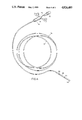
- FIG. 1 illustrates the stiffening means
- FIG. 2 shows an end view of the connector.
- FIG. 3 is a cross sectional view along line A--A of FIG. 2.
- FIG. 4 shows one embodiment of the present device used in conjunction with an enteral feeding tube.
- the present invention provides a device for guiding flexible tubing, i.e. a stylet.
- the stylet can be used in conjunction with enteral feeding tubing and other tubings having medical applications.
- the stylet comprises a connector having embedded therein one end of a stiffening means.
- the present stylet is so constructed that there are no sharp or pointed edges which may cause harm to the patient. Furthermore, flow through the connector in the present device is not impeded by the stiffening means.
- FIG. 1 shows the construction of the stiffening means 10 used in forming the present stylet.
- Stiffening means 10 comprises cable 12 which may be made of metal or a stiff polymeric material and enlarged portions 14 and 16 attached to the ends thereof. Cable 12 is formed by twisting a plurality of thinner strands of wire or polymeric materials, typically three. Enlarged portions 14 and 16 are joined to the ends of cable 12 by swaging, welding or other conventional method. As shown in FIG. 1, enlarged portions 12 and 14 are in the shape of a bullet, i.e. a cylinder having one end rounded to eliminate sharp corners or edges. It is understood that the enlarged portions are not limited to such shape. Any configuration can be used, as long as there are no sharp points or edges.
- enlarged portions 14 and 16 have a diameter which is greater than that of cable 12 to provide shoulder portions 18 and 20 which prevent cable 12 from being pulled out of the connector after cable 12 has been embedded therein.
- Cable 12 and enlarged portions 14 and 16 preferably are made of stainless steel whereas the cable between enlarged portions 14 and 16 preferably is coated with an inert polymeric material such as medical grade Teflon.
- uncoated cable 12 has a diameter of from about 0.026 to 0.030 inch and a Teflon coating thickness ranging from about 0.002 to 0.004 inch.
- Enlarged portions 14 and 16 may have a length of from about 0.120 to 0.180 inch and a diameter of from about 0.04 to 0.06 inch.
- the connector is provided with an off-centered through bore to provide a thick wall portion and a thin wall portion.
- One end (proximal) of cable 12 is embedded in the thick wall portion to form the stylet, whereas the other end (distal) is insertable into the flexible tubing to be guided by the stylet.
- FIGS. 2 and 3 show the end view and cross-sectional view of one embodiment of the connector in the present invention, respectively.
- connector plug 30 comprises large section 32 and small section 34, the connector being integrally formed.
- Large section 32 is provided with a central through bore 36.
- bore 36 is tapered from the outer end towards the center at an angle of from about 3° to 4° to facilitate insertion of syringes and the like.
- Outer wall 38 of large section 32 is preferably provided with flange portion 40 near the center of connector plug 30.
- large section 32 has a length of from about 0.375 to 0.425 inch, a maximum through bore diameter of from about 0.287 to about 0.297 inch.
- Outer wall 38 has an outside diameter of from about 0.362 to about 0.382 inch whereas flange portion 40 has an outside diameter of from about 0.390 to about 0.416 inch.
- Small section 34 of connector 30 is also provided with a through bore 42.
- through bore 42 is off-set from the centerline of small section 34 so as to form a thick wall portion 44 and thin wall portion 46 therein.
- Embedded in thick wall portion 44 is one end of cable 12 and the enlarged portion 14.
- cable 12 and thick wall portion 44 are co-axial.
- Cable 12 and enlarged portion 14 can be imbedded in connector 30 by insertion molding. That is to say, cable 12 with enlarged portion 14 attached securely thereto is placed in a molding machine and connector 30 is then formed over enlarged portion 14 by insertion molding. Since insertion molding is well known, a detailed description of this method is omitted.
- exterior wall of small section 34 comprises a constant diameter portion 48 and reduced diameter portion 50 so as to provide shoulder portion 52. Reduced diameter portion 50 has an outside diameter which decreases from the central portion of the connector plug 30 towards the outer end 54 of small section 34.
- small section 34 has a length of from about 0.390 to 0.410 inch.
- Constant diameter portion 48 has a diameter of from about 0.332 to about 0.342 inch.
- the taper in the outside diameter of small section 34 ranges from about 3° to 4°. Due to the presence of the off-set in through bore 42, thick shoulder portion 62 and thin shoulder portion 64 are formed. These shoulders are located at about the center of connector plug 30, i.e. large and small sections 32 and 34 are of approximately equal length. As shown in FIG. 3, through bores 36 and 42 are in communication, with through bore 36 being larger in diameter then through bore 42.
- Connector 30 is made of a polymeric material, such as polypropylene or polyvinylchloride.
- FIG. 4 shows the present stylet in use with an enteral feeding tubing.
- the stylet comprises connector 70 and cable 72.
- One end of cable 72 is inserted into enteral feeding tube 74.
- Feeding tube 74 in turn comprises female connector 76 at its proximal end, stem portion 78 and weighted bolus 80 at the distal end.
- the weighted bolus is provided with a plurality of discharge openings 82 which permit flow from within the feeding tube to the exterior thereof.
- One end of the cable 72 is housed within the tip of weighted bolus 80.
- the distal end 84 of bolus 80 is closed. However, it is understood that end 84 may be provided with an opening.
- the enteral feeding tubing 74 may comprise only a female connector at the proximal end and a stem portion having no weighted bolus connected to the distal end thereof.
- the distal end of the stem portion may be closed or open. When the distal end is closed, a plurality of discharge openings are provided adjacent the distal end of the stem portion.
- the present invention provides a stylet in which the stiffening means is so connected to the connector that no sharp edges or points are exposed.
- the stiffening means is so connected to the connector that no sharp edges or points are exposed.
Abstract
Description
Claims (22)
Priority Applications (1)
| Application Number | Priority Date | Filing Date | Title |
|---|---|---|---|
| US06/629,819 US4826485A (en) | 1984-07-11 | 1984-07-11 | Device for guiding tubings |
Applications Claiming Priority (1)
| Application Number | Priority Date | Filing Date | Title |
|---|---|---|---|
| US06/629,819 US4826485A (en) | 1984-07-11 | 1984-07-11 | Device for guiding tubings |
Publications (1)
| Publication Number | Publication Date |
|---|---|
| US4826485A true US4826485A (en) | 1989-05-02 |
Family
ID=24524627
Family Applications (1)
| Application Number | Title | Priority Date | Filing Date |
|---|---|---|---|
| US06/629,819 Expired - Fee Related US4826485A (en) | 1984-07-11 | 1984-07-11 | Device for guiding tubings |
Country Status (1)
| Country | Link |
|---|---|
| US (1) | US4826485A (en) |
Cited By (14)
| Publication number | Priority date | Publication date | Assignee | Title |
|---|---|---|---|---|
| US5217026A (en) * | 1992-04-06 | 1993-06-08 | Kingston Technologies, Inc. | Guidewires with lubricious surface and method of their production |
| US5368048A (en) * | 1993-04-19 | 1994-11-29 | Stoy; George P. | Method of making radio-opaque tipped, sleeved guidewire and product |
| US5382238A (en) * | 1993-05-20 | 1995-01-17 | Quinton Instrument Company | Catheter stiffeners |
| WO1996025968A1 (en) * | 1995-02-21 | 1996-08-29 | Abbott Laboratories | Stylet device for guiding an enteral feeding tube |
| US5611787A (en) * | 1994-10-13 | 1997-03-18 | Methodist Hospital Of Indiana, Inc. | Method and device for gastric line insertion |
| US5634883A (en) * | 1991-05-29 | 1997-06-03 | Origin Medsystems, Inc. | Apparatus for peritoneal retraction |
| US5639810A (en) * | 1993-04-15 | 1997-06-17 | Cobe Laboratories, Inc. | Internally lubricated elastomers for use in biomedical applications |
| US20020133142A1 (en) * | 1999-07-19 | 2002-09-19 | Deniega Jose Castillo | Catheter for uniform delivery of medication |
| US20060135941A1 (en) * | 1999-07-19 | 2006-06-22 | Porto James D | Anti-microbial catheter |
| US20090165784A1 (en) * | 2007-12-28 | 2009-07-02 | Tyco Healthcare Group Lp | Lubricious intubation device |
| GB2532717A (en) * | 2014-11-19 | 2016-06-01 | Alan Coles Phillip | Nasogastric tube introducer |
| WO2020153271A1 (en) * | 2019-01-21 | 2020-07-30 | 株式会社ジェイ・エム・エス | Stylet device |
| WO2020223805A1 (en) | 2019-05-06 | 2020-11-12 | Bles Biochemicals Incorporated | Feeding tube with integrated stylet |
| JP2022500219A (en) * | 2018-09-21 | 2022-01-04 | クック・メディカル・テクノロジーズ・リミテッド・ライアビリティ・カンパニーCook Medical Technologies Llc | Introducer for uterine tamponade assembly with echogenic elements and how to use it |
Citations (3)
| Publication number | Priority date | Publication date | Assignee | Title |
|---|---|---|---|---|
| US3128769A (en) * | 1962-07-23 | 1964-04-14 | Abbott Lab | Catheter assembly |
| US4137916A (en) * | 1976-11-22 | 1979-02-06 | Travenol Laboratories, Inc. | Catheter plug assembly |
| US4388076A (en) * | 1981-02-11 | 1983-06-14 | Biosearch Medical Products Inc. | Intubating device |
-
1984
- 1984-07-11 US US06/629,819 patent/US4826485A/en not_active Expired - Fee Related
Patent Citations (3)
| Publication number | Priority date | Publication date | Assignee | Title |
|---|---|---|---|---|
| US3128769A (en) * | 1962-07-23 | 1964-04-14 | Abbott Lab | Catheter assembly |
| US4137916A (en) * | 1976-11-22 | 1979-02-06 | Travenol Laboratories, Inc. | Catheter plug assembly |
| US4388076A (en) * | 1981-02-11 | 1983-06-14 | Biosearch Medical Products Inc. | Intubating device |
Cited By (30)
| Publication number | Priority date | Publication date | Assignee | Title |
|---|---|---|---|---|
| US5634883A (en) * | 1991-05-29 | 1997-06-03 | Origin Medsystems, Inc. | Apparatus for peritoneal retraction |
| US5643178A (en) * | 1991-05-29 | 1997-07-01 | Origin Medsystems, Inc. | Method for peritoneal retration |
| US5217026A (en) * | 1992-04-06 | 1993-06-08 | Kingston Technologies, Inc. | Guidewires with lubricious surface and method of their production |
| US5639810A (en) * | 1993-04-15 | 1997-06-17 | Cobe Laboratories, Inc. | Internally lubricated elastomers for use in biomedical applications |
| US5368048A (en) * | 1993-04-19 | 1994-11-29 | Stoy; George P. | Method of making radio-opaque tipped, sleeved guidewire and product |
| US5382238A (en) * | 1993-05-20 | 1995-01-17 | Quinton Instrument Company | Catheter stiffeners |
| US5611787A (en) * | 1994-10-13 | 1997-03-18 | Methodist Hospital Of Indiana, Inc. | Method and device for gastric line insertion |
| WO1996025968A1 (en) * | 1995-02-21 | 1996-08-29 | Abbott Laboratories | Stylet device for guiding an enteral feeding tube |
| US5658253A (en) * | 1995-02-21 | 1997-08-19 | Abbott Laboratories | Stylet device for guiding an enteral feeding tube |
| US7527609B2 (en) * | 1999-07-19 | 2009-05-05 | I-Flow Corporation | Catheter for uniform delivery of medication |
| US8343135B2 (en) | 1999-07-19 | 2013-01-01 | Kimberly-Clark Worldwide, Inc. | Anti-microbial catheter |
| US20060135941A1 (en) * | 1999-07-19 | 2006-06-22 | Porto James D | Anti-microbial catheter |
| US7465291B2 (en) | 1999-07-19 | 2008-12-16 | I-Flow Corporation | Method of fluid delivery and catheters for use with same |
| US20090093790A1 (en) * | 1999-07-19 | 2009-04-09 | Iflow Corporation | Method of fluid delivery and catheters for use with same |
| US20020133142A1 (en) * | 1999-07-19 | 2002-09-19 | Deniega Jose Castillo | Catheter for uniform delivery of medication |
| US7547302B2 (en) | 1999-07-19 | 2009-06-16 | I-Flow Corporation | Anti-microbial catheter |
| US20040116896A1 (en) * | 1999-07-19 | 2004-06-17 | Massengale Roger Dillard | Method of fluid delivery and catheters for use with same |
| US20090187152A1 (en) * | 1999-07-19 | 2009-07-23 | L-Flow Corporation | Anti-microbial catheter |
| US7959623B2 (en) | 1999-07-19 | 2011-06-14 | I-Flow Corporation | Method of fluid delivery and catheters for use with same |
| US8328771B2 (en) | 1999-07-19 | 2012-12-11 | Roger Dillard Massengale | Method for fluid delivery and catheters for use with same |
| US20090165784A1 (en) * | 2007-12-28 | 2009-07-02 | Tyco Healthcare Group Lp | Lubricious intubation device |
| GB2532717A (en) * | 2014-11-19 | 2016-06-01 | Alan Coles Phillip | Nasogastric tube introducer |
| GB2532717B (en) * | 2014-11-19 | 2020-07-15 | Alan Coles Phillip | Introducer Rod |
| JP2022500219A (en) * | 2018-09-21 | 2022-01-04 | クック・メディカル・テクノロジーズ・リミテッド・ライアビリティ・カンパニーCook Medical Technologies Llc | Introducer for uterine tamponade assembly with echogenic elements and how to use it |
| US11583281B2 (en) | 2018-09-21 | 2023-02-21 | Cook Medical Technologies Llc | Introducer for uterine tamponade assembly with echogenic element and methods of using the same |
| WO2020153271A1 (en) * | 2019-01-21 | 2020-07-30 | 株式会社ジェイ・エム・エス | Stylet device |
| JP2020115969A (en) * | 2019-01-21 | 2020-08-06 | 株式会社ジェイ・エム・エス | Stylet apparatus |
| CN113316447A (en) * | 2019-01-21 | 2021-08-27 | 株式会社Jms | Tube core device |
| WO2020223805A1 (en) | 2019-05-06 | 2020-11-12 | Bles Biochemicals Incorporated | Feeding tube with integrated stylet |
| EP3965718A4 (en) * | 2019-05-06 | 2023-06-14 | Bles Biochemicals Incorporated | Feeding tube with integrated stylet |
Similar Documents
| Publication | Publication Date | Title |
|---|---|---|
| US4826485A (en) | Device for guiding tubings | |
| US4388076A (en) | Intubating device | |
| US5800407A (en) | Multiple hole epidural catheter | |
| US5941823A (en) | Indwelling catheter | |
| EP0783336B1 (en) | R-x safety catheter | |
| US5242389A (en) | Enteral feeding tube enteral feeding tube with separate stylet lumen | |
| US6245029B1 (en) | Stylet and connector therefor | |
| US5498249A (en) | Catheter stylet | |
| US5746734A (en) | Introducer cartridge for delivering an embolization device | |
| US5611787A (en) | Method and device for gastric line insertion | |
| US4791939A (en) | Stylet for use with an implantable pacing lead | |
| US6517518B2 (en) | Tool for facilitating the connecting of a catheter or other tubular member onto a guide-wire without access to the ends of the guide-wire | |
| US6293927B1 (en) | Stationary central tunnel dialysis catheter with optional separable sheath | |
| US5385563A (en) | Urodynamic catheter | |
| US8002763B2 (en) | Catheter flushing mandrel | |
| US4150676A (en) | Endotracheal tubes with intubation direction control means | |
| US5735813A (en) | Double lumen introducing needle | |
| US20020055714A1 (en) | Method and apparatus for the non-surgical placement of a subcutaneously tunnelled catheter through the skin into a central vein | |
| EP0121556A1 (en) | Tubular guiding device for introducing a catheter or tube into a vein or other tubular cavity | |
| JPH11504830A (en) | Catheter for administering liquids | |
| DE2132864A1 (en) | Fiber optic catheter | |
| WO1997020530A1 (en) | Device and method for inserting a flexible element into soft tissue | |
| US6223070B1 (en) | Indwelling catheter | |
| US4659328A (en) | Stylet | |
| JPH05269205A (en) | Anesthetic tool |
Legal Events
| Date | Code | Title | Description |
|---|---|---|---|
| AS | Assignment |
Owner name: MEDICAL RESEARCH ASSOCIATES, LTD., #2, 12707 U.S. Free format text: ASSIGNMENT OF ASSIGNORS INTEREST.;ASSIGNOR:JOHNSON, THEODORE D.;REEL/FRAME:004291/0700 Effective date: 19840620 |
|
| AS | Assignment |
Owner name: CONCEPT POLYMER TECHNOLOGIES, INC. Free format text: ASSIGNMENT OF ASSIGNORS INTEREST.;ASSIGNOR:MEDICAL RESEARCH ASSOCIATES, LTD., #2;REEL/FRAME:004783/0903 Effective date: 19870805 |
|
| FEPP | Fee payment procedure |
Free format text: PAYOR NUMBER ASSIGNED (ORIGINAL EVENT CODE: ASPN); ENTITY STATUS OF PATENT OWNER: LARGE ENTITY |
|
| AS | Assignment |
Owner name: LINVATEC CORPORATION A CORPORATION OF FL, FLORI Free format text: ASSIGNMENT OF ASSIGNORS INTEREST.;ASSIGNOR:CONCEPT POLYMER TECHNOLOGIES, INC., A FL CORPORATION;REEL/FRAME:006047/0965 Effective date: 19920320 |
|
| FPAY | Fee payment |
Year of fee payment: 4 |
|
| AS | Assignment |
Owner name: BRISTOL-MYERS SQUIBB COMPANY, NEW YORK Free format text: ASSIGNMENT OF ASSIGNORS INTEREST;ASSIGNOR:LINVATEC CORPORATION;REEL/FRAME:006547/0461 Effective date: 19930527 |
|
| FPAY | Fee payment |
Year of fee payment: 8 |
|
| REMI | Maintenance fee reminder mailed | ||
| LAPS | Lapse for failure to pay maintenance fees | ||
| FP | Lapsed due to failure to pay maintenance fee |
Effective date: 20010502 |
|
| STCH | Information on status: patent discontinuation |
Free format text: PATENT EXPIRED DUE TO NONPAYMENT OF MAINTENANCE FEES UNDER 37 CFR 1.362 |