US4842555A - Circular DIN receptacle cover for latching plug - Google Patents
Circular DIN receptacle cover for latching plug Download PDFInfo
- Publication number
- US4842555A US4842555A US07/202,276 US20227688A US4842555A US 4842555 A US4842555 A US 4842555A US 20227688 A US20227688 A US 20227688A US 4842555 A US4842555 A US 4842555A
- Authority
- US
- United States
- Prior art keywords
- finger
- mating
- shield
- protuberance
- free end
- Prior art date
- Legal status (The legal status is an assumption and is not a legal conclusion. Google has not performed a legal analysis and makes no representation as to the accuracy of the status listed.)
- Expired - Lifetime
Links
- 230000013011 mating Effects 0.000 claims abstract description 62
- 239000002184 metal Substances 0.000 claims abstract description 7
- 239000000758 substrate Substances 0.000 claims description 4
- 230000008093 supporting effect Effects 0.000 claims description 4
- 230000000881 depressing effect Effects 0.000 claims 3
- 230000000994 depressogenic effect Effects 0.000 description 3
- 230000000295 complement effect Effects 0.000 description 1
- 230000000694 effects Effects 0.000 description 1
- 230000000717 retained effect Effects 0.000 description 1
Images

Classifications
-
- H—ELECTRICITY
- H01—ELECTRIC ELEMENTS
- H01R—ELECTRICALLY-CONDUCTIVE CONNECTIONS; STRUCTURAL ASSOCIATIONS OF A PLURALITY OF MUTUALLY-INSULATED ELECTRICAL CONNECTING ELEMENTS; COUPLING DEVICES; CURRENT COLLECTORS
- H01R13/00—Details of coupling devices of the kinds covered by groups H01R12/70 or H01R24/00 - H01R33/00
- H01R13/62—Means for facilitating engagement or disengagement of coupling parts or for holding them in engagement
- H01R13/627—Snap or like fastening
-
- H—ELECTRICITY
- H01—ELECTRIC ELEMENTS
- H01R—ELECTRICALLY-CONDUCTIVE CONNECTIONS; STRUCTURAL ASSOCIATIONS OF A PLURALITY OF MUTUALLY-INSULATED ELECTRICAL CONNECTING ELEMENTS; COUPLING DEVICES; CURRENT COLLECTORS
- H01R13/00—Details of coupling devices of the kinds covered by groups H01R12/70 or H01R24/00 - H01R33/00
- H01R13/648—Protective earth or shield arrangements on coupling devices, e.g. anti-static shielding
- H01R13/658—High frequency shielding arrangements, e.g. against EMI [Electro-Magnetic Interference] or EMP [Electro-Magnetic Pulse]
- H01R13/6581—Shield structure
- H01R13/6582—Shield structure with resilient means for engaging mating connector
-
- H—ELECTRICITY
- H01—ELECTRIC ELEMENTS
- H01R—ELECTRICALLY-CONDUCTIVE CONNECTIONS; STRUCTURAL ASSOCIATIONS OF A PLURALITY OF MUTUALLY-INSULATED ELECTRICAL CONNECTING ELEMENTS; COUPLING DEVICES; CURRENT COLLECTORS
- H01R13/00—Details of coupling devices of the kinds covered by groups H01R12/70 or H01R24/00 - H01R33/00
- H01R13/648—Protective earth or shield arrangements on coupling devices, e.g. anti-static shielding
- H01R13/658—High frequency shielding arrangements, e.g. against EMI [Electro-Magnetic Interference] or EMP [Electro-Magnetic Pulse]
- H01R13/6591—Specific features or arrangements of connection of shield to conductive members
- H01R13/6594—Specific features or arrangements of connection of shield to conductive members the shield being mounted on a PCB and connected to conductive members
Definitions
- This invention relates to surface mounted, shielded electrical connectors of the type known as shielded miniature DIN connectors and concerns means for latching mating electrical connectors thereto.
- the first mating portion is surrounded by a ring of spring fingers, projecting from a front shield of the first connector for resiliently engaging the shielding of said second mating portion when it is mated with the first mating portion.
- U.S. Pat. No. 4,548,455 discloses means for supporting such a latch arm when the connectors have been mated, so that the protuberance is secured in its latching position against a latching shoulder, said means being actable to release the arm, so that the protuberance can be depressed by the latching shoulder in order to allow the connectors to be unmated.
- the need for forming a latching shoulder in the housing of the first connector, where the first connector has a front shield from which spring fingers extend about the first mating portion is avoided by providing intermediate a pair of the spring fingers on said shield, a rudimentary latching finger, that is to say a latching finger which is substantially shorter than the resilient fingers and behind which the protuberance latches when the first and second connectors have been mated.
- a rudimentary latching finger that is to say a latching finger which is substantially shorter than the resilient fingers and behind which the protuberance latches when the first and second connectors have been mated.
- the second connector is provided with said means for supporting and releasing the latch arm
- the latching finger and the protuberance are preferably provided with co-operating surfaces which are configured to allow the protuberance to slide under the latching finger when the latch arm has been released and the connectors are to be unmated.
- the latching finger is preferably rectilinear and extends obliquely towards the first mating portion, having a smooth surface facing towards the first mating portion, the protuberance having an arcuate surface to assist its depression by the latching finger, and a flat summit for sliding engagement with the flat surface of the latching finger.
- the spring fingers may extend from the periphery of a circular opening in the front wall of a one-piece metal shield enclosing at least a top wall and side walls of the first connector which may have a substantially rectangular cross-section connector body into which the first mating portion projects, the latter having a mating face spaced back somewhat from the said front wall.
- the latching finger may very simply be provided, by forming the front wall, initially, only with the spring fingers and then severing one of the spring fingers to provide the latching finger.
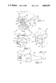
- FIG. 1 is an isometric view of a shielded, surface mounted electrical connector having a metal shield
- FIG. 2 is an axial sectional view of the connector of FIG. 1;
- FIG. 3 is a reduced scale axial sectional view of the shield
- FIG. 4 is a fragmentary, isometric, enlarged, front view of the shield
- FIG. 5 is a top plan view, drawn to a reduced scale, of a shielded second electrical connector for mating with the connector shown in FIG. 1;
- FIG. 6 is a diagramatic view taken on the lines 6--6 of FIG. 4, illustrating the second connector when it has been mated with the connector shown in FIG. 1.
- a shielded first electrical connector 10 for mounting on a substrate comprises a one-piece metal shield 12 and a substantially rectangular cross-section, one-piece, molded, insulating connector body 14.
- a circular cross-section mating member in the form of a plug portion 16 for mating with a mating member, in the form of a circular cross-section externally shielded, electrical socket 18 of a second electrical connector 20.
- the socket 18 has a metal shield 19, and electrical pins 17 projecting into the socket 18.
- the body 14 has a central portion 22 from which the plug portion 16 projects
- the shield 12 comprises a top wall 24, a pair of side walls 26, each adjacent thereto, depending from opposite lateral edges thereof.
- a front wall 28 adjacent to the top wall 24 and the side walls 26, is formed integrally therewith and has a circular, through opening 30 therein, for receiving the socket 18.
- the opening 30 has a circular edge 32 from which project a series of resilient, cantilever fingers 34 of the shield 12, rearwardly thereof, for engaging the external shield 19 of the socket 18, the fingers 34 being arranged in a ring about the edge 32 and being spaced from one another thereabout.
- Each finger 34 is formed with a joggle 40 spaced back from its free end 38 to provide a raised shoulder 42 for engaging the shield 19.
- the shield 12 is provided with in-turned flanges 48 and 50 and with detents 52 which anchor it to the body 14. There depend from the side walls 26, mounting feet 54 and from an extension 55 of the front wall 28, mounting feet 58, the feet 54 and 58 being for securing the shield 12, and thus the body 14, to the said substrate.
- the plug portion 16 is formed with terminal receiving parallel cavities 62 which extend therethrough and also through the central portion 22 of the body 14 and open into a mating face 66 of the plug portion 16 and into a terminal receiving face 70 of the portion 22.
- the portion 22 has projecting forwardly therefrom a hood 68 surrounding the plug portion 16 in spaced relationship thereto, to allow the socket 18 to be mated therewith.
- the plug portion 16 has an axial keyway 65 for slidably receiving a complementary key 67 in the socket 18.
- Each cavity 62 has secured therein an electrical receptacle 72 for receiving a respective one of the pins 17 of the socket 18.
- the body 14 has a bottom, mounting face 74 with stand-off lugs 78 for mounting on said substrate.
- a rudimentary latching finger 80 connected to the front wall 28 by way of a smoothly arcuate part 81 presenting a camming surface 83 bowed generally forwardly of the shield 12.
- the finger 80 projects slightly obliquely, towards the plug portion 16 and is substantially shorter than the fingers 34, being positioned between two of the fingers 34, and evenly spaced therefrom.
- the finger 80 which is of constant rectangular cross-section, has a flat surface 82 facing towards the plug portion 16 and terminates in a flat free end 84 which is perpendicular to the surface 82.
- the finger 80 is positioned diametrically opposite to the finger 34 shown in FIG.
- the shield 12 was initially formed with integral fingers 38 from the portion of surface 28 that otherwise would enclose opening 30 only, the top finger 38 then being severed, back from its joggle 40 to provide the latching finger 80.
- the second connector 20 (FIGS. 5 and 6) comprises an insulating body 86 within which the shield 19 extends from the socket 18 and which receives an electrical cable C, individual leads of which (not shown) are connected to respective connecting portions (not shown) of the pins 17.
- a resiliently flexible cantilever latch arm 88 having thereon proximate to its free end, a protuberance 90, projecting through an opening 91 in the shield 19 so that it is upstanding thereabove.
- the protuberance 90 has a first arcuate surface 92 facing rearwardly of the socket 18 and a second arcuate surface 94 facing forwardly thereof, the surfaces 92 and 94 adjoining a flat summit 96 of the protuberance 90.
- a stiffly resilient support bar 98 which is connected to a slide (not shown) loaded by a spring (not shown) in the body 86 and which is in turn connected to a sleeve 100 slidably mounted on the body 86.
- the slide and thus the support bar 98 are normally urged towards an advanced supporting position beneath the arm 88, by the loading spring and can be retracted by pulling the sleeve 100 rearwardly of the body 86, to allow the arm 88 to flex freely downwardly into the socket 18, as disclosed in detail in U.S. Pat. No. 4,548,455, which is incorporated herein by reference.
- the socket 18 is inserted through the circular opening 30 in the shield 12 so that the key 67 engages in the keyway 65, in a mating direction indicated by the arrow A in FIG. 6, whereby each pin 17 enters a respective cavity 62 so as to be engaged in the respective receptacle 72 in the cavity 62.
- the slide and thus the sleeve 100 are, prior to the mating operation, in said advanced position whereby the support bar 98 extends beneath the arm 88.
- the socket 18 is permitted to advance into mating relationship with the plug portion 16 because the protuberance 90 is depressed by engagement of its surface 94 with the camming surface 83 of the rudimentary finger 80, against the resilient action of the support bar 98, the finger 80 being raised from the oblique position in which it is shown in FIGS. 2 and 3, onto the flat summit 96 of the protuberance 90.
- the protuberance 90 has passed the free end 84 of the finger 80, the protuberance 90 resiles so as to latch there behind as shown in FIG. 6.
- the connectors 10 and 20 are accordingly firmly retained in mating relationship, because the arm 88, being supported by the support bar 98, cannot be depressed by the finger 80 simply by pulling on the cable C.
- the sleeve 100 is pulled rearwardly thereby to retract the support bar 98 from beneath the arm 88, leaving the arm 88 free to flex inwardly of the socket 18.
- the connector 20 is pulled away from the connector 10, by pulling on the sleeve 100 and, the protuberance 90 guided by its surface 92, slips under the finger 80, the summit 96 of the protuberance 90 slides on the surface 82 of the finger 80 until the protuberance 90 passes the surface 92.
- the connectors 10 and 20 cannot be unmated by pulling on the cable C, as the sleeve 100 will not thereby be retracted.
Abstract
Description
Claims (10)
Priority Applications (8)
| Application Number | Priority Date | Filing Date | Title |
|---|---|---|---|
| US07/202,276 US4842555A (en) | 1988-06-03 | 1988-06-03 | Circular DIN receptacle cover for latching plug |
| CA000599066A CA1303163C (en) | 1988-06-03 | 1989-05-09 | One-piece latching shield for a circular din connector |
| EP89305297A EP0344972B1 (en) | 1988-06-03 | 1989-05-25 | One-piece latching shield for a circular din connector |
| DE68914194T DE68914194T2 (en) | 1988-06-03 | 1989-05-25 | One-piece, lockable screen for a circular DIN connector. |
| ES89305297T ES2050799T3 (en) | 1988-06-03 | 1989-05-25 | SINGLE PIECE HITCHING SCREEN FOR A DIN CIRCULAR CONNECTOR. |
| KR1019890007587A KR940010426B1 (en) | 1988-06-03 | 1989-06-02 | One piece latching shield for a circular din connector |
| JP1140942A JP2928267B2 (en) | 1988-06-03 | 1989-06-02 | Shielded electrical connector |
| BR898902563A BR8902563A (en) | 1988-06-03 | 1989-06-02 | ARMORED ELECTRIC CONNECTOR |
Applications Claiming Priority (1)
| Application Number | Priority Date | Filing Date | Title |
|---|---|---|---|
| US07/202,276 US4842555A (en) | 1988-06-03 | 1988-06-03 | Circular DIN receptacle cover for latching plug |
Publications (1)
| Publication Number | Publication Date |
|---|---|
| US4842555A true US4842555A (en) | 1989-06-27 |
Family
ID=22749193
Family Applications (1)
| Application Number | Title | Priority Date | Filing Date |
|---|---|---|---|
| US07/202,276 Expired - Lifetime US4842555A (en) | 1988-06-03 | 1988-06-03 | Circular DIN receptacle cover for latching plug |
Country Status (1)
| Country | Link |
|---|---|
| US (1) | US4842555A (en) |
Cited By (35)
| Publication number | Priority date | Publication date | Assignee | Title |
|---|---|---|---|---|
| US4913664A (en) * | 1988-11-25 | 1990-04-03 | Molex Incorporated | Miniature circular DIN connector |
| US4936795A (en) * | 1988-10-04 | 1990-06-26 | Hirose Electric Co., Ltd. | Electrical connector |
| US4938714A (en) * | 1988-10-04 | 1990-07-03 | Hirose Electric Co., Ltd. | Electrical connector |
| US4946400A (en) * | 1988-10-04 | 1990-08-07 | Hirose Electric Co., Ltd. | Surface mounted electrical connector |
| US5017158A (en) * | 1990-05-02 | 1991-05-21 | Pan-International Industrial Corp. | Structure of receptacle for electric connector with self-locking and electric shield mechanism |
| US5037330A (en) * | 1990-11-30 | 1991-08-06 | Amp Corporated | Stacked circular DIN connector |
| US5041022A (en) * | 1988-09-21 | 1991-08-20 | Hosiden Electronics Co., Ltd. | Socket with a lock |
| US5083945A (en) * | 1991-02-01 | 1992-01-28 | Molex Incorporated | Shielded electrical connector assembly |
| US5097389A (en) * | 1989-03-03 | 1992-03-17 | Murata Manufacturing Co., Ltd. | Structure for fixing feedthrough capacitor in high-frequency device and manufacturing method of high-frequency device |
| US5178562A (en) * | 1991-10-17 | 1993-01-12 | Epson Portland, Inc. | Contact member for miniature electrical circuit connector |
| US5186633A (en) * | 1991-09-03 | 1993-02-16 | Amp Incorporated | Surface mount electrical connector with interleaved solder tails |
| US5192228A (en) * | 1991-09-16 | 1993-03-09 | Amp Inc. | Shielded surface mount electrical connector with integral barbed board lock |
| US5207597A (en) * | 1991-06-21 | 1993-05-04 | Amp Incorporated | Shielded connector with dual cantilever panel grounding beam |
| US5221212A (en) * | 1992-08-27 | 1993-06-22 | Amp Incorporated | Shielding a surface mount electrical connector |
| US5224882A (en) * | 1991-05-31 | 1993-07-06 | Tronomed, Inc. | Medical electrical connector for flexible electrodes |
| US5254010A (en) * | 1992-09-16 | 1993-10-19 | Amp Incorporated | Securing a surface mount electrical connector in a metal shielding shell |
| US5288248A (en) * | 1991-10-28 | 1994-02-22 | Foxconn International | Totally shielded DIN connector |
| EP0584937A2 (en) * | 1992-08-27 | 1994-03-02 | The Whitaker Corporation | Shielding a surface mount electrical connector |
| US5738544A (en) * | 1996-06-27 | 1998-04-14 | The Whitaker Corporation | Shielded electrical connector |
| US5749741A (en) * | 1996-07-12 | 1998-05-12 | Minnesota Mining And Manufacturing Company | Electrical connector with ground clip |
| US5755595A (en) * | 1996-06-27 | 1998-05-26 | Whitaker Corporation | Shielded electrical connector |
| US5775946A (en) * | 1996-08-23 | 1998-07-07 | Amphenol Corporation | Shielded multi-port connector and method of assembly |
| US6217372B1 (en) | 1999-10-08 | 2001-04-17 | Tensolite Company | Cable structure with improved grounding termination in the connector |
| KR100325039B1 (en) * | 1999-02-04 | 2002-03-04 | 루이스 에이. 헥트 | Adapter frame assembly for electrical connectors |
| US6428344B1 (en) | 2000-07-31 | 2002-08-06 | Tensolite Company | Cable structure with improved termination connector |
| US6607308B2 (en) | 2001-02-12 | 2003-08-19 | E20 Communications, Inc. | Fiber-optic modules with shielded housing/covers having mixed finger types |
| US6659655B2 (en) | 2001-02-12 | 2003-12-09 | E20 Communications, Inc. | Fiber-optic modules with housing/shielding |
| US6857899B2 (en) | 1999-10-08 | 2005-02-22 | Tensolite Company | Cable structure with improved grounding termination in the connector |
| US7934960B1 (en) * | 2009-12-19 | 2011-05-03 | Cheng Uei Precision Industry Co., Ltd. | Power jack connector |
| US20120015549A1 (en) * | 2009-01-22 | 2012-01-19 | Bok-Hee Youn | Clip-type elastic contact piece and shielded connector housing assembly having the same |
| US20140335739A1 (en) * | 2012-01-25 | 2014-11-13 | Yazaki Corporation | Connector Unit |
| US20150295335A1 (en) * | 2014-04-10 | 2015-10-15 | Foxconn Interconnect Technology Limited | Electrical connector with improved contacts |
| US20170077644A1 (en) * | 2013-07-19 | 2017-03-16 | Foxconn Interconnect Technology Limited | Flippable electrical connector |
| DE102017115914B3 (en) * | 2017-07-14 | 2018-10-31 | HARTING Electronics GmbH | Printed circuit board connector with a screen element |
| CN110838642A (en) * | 2019-11-07 | 2020-02-25 | 丰县杰兰特电动车有限公司 | Anti-drop plug for electric vehicle charger |
Citations (7)
| Publication number | Priority date | Publication date | Assignee | Title |
|---|---|---|---|---|
| US4337989A (en) * | 1980-05-28 | 1982-07-06 | Amp Incorporated | Electromagnetic shielded connector |
| US4493525A (en) * | 1983-01-31 | 1985-01-15 | Amp Incorporated | Electrical plug connector and receptacle therefor |
| US4548455A (en) * | 1983-10-24 | 1985-10-22 | Hosiden Electronics Co., Ltd. | Connector with lock mechanism |
| US4611878A (en) * | 1983-01-31 | 1986-09-16 | Amp Incorporated | Electrical plug connector |
| US4634208A (en) * | 1983-01-31 | 1987-01-06 | Amp Incorporated | Electrical plug connector and method of terminating a cable therewith |
| US4637669A (en) * | 1985-06-07 | 1987-01-20 | Hosiden Electronics Co., Ltd. | Connector socket |
| US4695105A (en) * | 1984-12-20 | 1987-09-22 | Amp Incorporated | Filtered electrical receptacle |
-
1988
- 1988-06-03 US US07/202,276 patent/US4842555A/en not_active Expired - Lifetime
Patent Citations (7)
| Publication number | Priority date | Publication date | Assignee | Title |
|---|---|---|---|---|
| US4337989A (en) * | 1980-05-28 | 1982-07-06 | Amp Incorporated | Electromagnetic shielded connector |
| US4493525A (en) * | 1983-01-31 | 1985-01-15 | Amp Incorporated | Electrical plug connector and receptacle therefor |
| US4611878A (en) * | 1983-01-31 | 1986-09-16 | Amp Incorporated | Electrical plug connector |
| US4634208A (en) * | 1983-01-31 | 1987-01-06 | Amp Incorporated | Electrical plug connector and method of terminating a cable therewith |
| US4548455A (en) * | 1983-10-24 | 1985-10-22 | Hosiden Electronics Co., Ltd. | Connector with lock mechanism |
| US4695105A (en) * | 1984-12-20 | 1987-09-22 | Amp Incorporated | Filtered electrical receptacle |
| US4637669A (en) * | 1985-06-07 | 1987-01-20 | Hosiden Electronics Co., Ltd. | Connector socket |
Non-Patent Citations (2)
| Title |
|---|
| AMP Catalog 83 700, Rev. 10 86. * |
| AMP Catalog 83-700, Rev. 10-86. |
Cited By (46)
| Publication number | Priority date | Publication date | Assignee | Title |
|---|---|---|---|---|
| US5041022A (en) * | 1988-09-21 | 1991-08-20 | Hosiden Electronics Co., Ltd. | Socket with a lock |
| US4936795A (en) * | 1988-10-04 | 1990-06-26 | Hirose Electric Co., Ltd. | Electrical connector |
| US4938714A (en) * | 1988-10-04 | 1990-07-03 | Hirose Electric Co., Ltd. | Electrical connector |
| US4946400A (en) * | 1988-10-04 | 1990-08-07 | Hirose Electric Co., Ltd. | Surface mounted electrical connector |
| US4913664A (en) * | 1988-11-25 | 1990-04-03 | Molex Incorporated | Miniature circular DIN connector |
| US5097389A (en) * | 1989-03-03 | 1992-03-17 | Murata Manufacturing Co., Ltd. | Structure for fixing feedthrough capacitor in high-frequency device and manufacturing method of high-frequency device |
| US5017158A (en) * | 1990-05-02 | 1991-05-21 | Pan-International Industrial Corp. | Structure of receptacle for electric connector with self-locking and electric shield mechanism |
| US5037330A (en) * | 1990-11-30 | 1991-08-06 | Amp Corporated | Stacked circular DIN connector |
| US5083945A (en) * | 1991-02-01 | 1992-01-28 | Molex Incorporated | Shielded electrical connector assembly |
| US5224882A (en) * | 1991-05-31 | 1993-07-06 | Tronomed, Inc. | Medical electrical connector for flexible electrodes |
| US5207597A (en) * | 1991-06-21 | 1993-05-04 | Amp Incorporated | Shielded connector with dual cantilever panel grounding beam |
| US5186633A (en) * | 1991-09-03 | 1993-02-16 | Amp Incorporated | Surface mount electrical connector with interleaved solder tails |
| US5192228A (en) * | 1991-09-16 | 1993-03-09 | Amp Inc. | Shielded surface mount electrical connector with integral barbed board lock |
| US5178562A (en) * | 1991-10-17 | 1993-01-12 | Epson Portland, Inc. | Contact member for miniature electrical circuit connector |
| US5288248A (en) * | 1991-10-28 | 1994-02-22 | Foxconn International | Totally shielded DIN connector |
| US5221212A (en) * | 1992-08-27 | 1993-06-22 | Amp Incorporated | Shielding a surface mount electrical connector |
| EP0584937A2 (en) * | 1992-08-27 | 1994-03-02 | The Whitaker Corporation | Shielding a surface mount electrical connector |
| EP0584937A3 (en) * | 1992-08-27 | 1994-07-13 | Whitaker Corp | Shielding a surface mount electrical connector |
| US5254010A (en) * | 1992-09-16 | 1993-10-19 | Amp Incorporated | Securing a surface mount electrical connector in a metal shielding shell |
| US5738544A (en) * | 1996-06-27 | 1998-04-14 | The Whitaker Corporation | Shielded electrical connector |
| US5755595A (en) * | 1996-06-27 | 1998-05-26 | Whitaker Corporation | Shielded electrical connector |
| US5893766A (en) * | 1996-07-12 | 1999-04-13 | Minnesota Mining And Manufacturing Company | Electrical connector with ground clip |
| US5749741A (en) * | 1996-07-12 | 1998-05-12 | Minnesota Mining And Manufacturing Company | Electrical connector with ground clip |
| US5775946A (en) * | 1996-08-23 | 1998-07-07 | Amphenol Corporation | Shielded multi-port connector and method of assembly |
| KR100325039B1 (en) * | 1999-02-04 | 2002-03-04 | 루이스 에이. 헥트 | Adapter frame assembly for electrical connectors |
| US6217372B1 (en) | 1999-10-08 | 2001-04-17 | Tensolite Company | Cable structure with improved grounding termination in the connector |
| US6394839B2 (en) | 1999-10-08 | 2002-05-28 | Tensolite Company | Cable structure with improved grounding termination in the connector |
| US6857899B2 (en) | 1999-10-08 | 2005-02-22 | Tensolite Company | Cable structure with improved grounding termination in the connector |
| US6428344B1 (en) | 2000-07-31 | 2002-08-06 | Tensolite Company | Cable structure with improved termination connector |
| US6823587B2 (en) | 2000-07-31 | 2004-11-30 | Tensolite Company | Method of making a cable structure for data signal transmission |
| US6607308B2 (en) | 2001-02-12 | 2003-08-19 | E20 Communications, Inc. | Fiber-optic modules with shielded housing/covers having mixed finger types |
| US6659655B2 (en) | 2001-02-12 | 2003-12-09 | E20 Communications, Inc. | Fiber-optic modules with housing/shielding |
| US8535095B2 (en) * | 2009-01-22 | 2013-09-17 | Ls Cable & System Ltd. | Clip-type elastic contact piece and shielded connector housing assembly having the same |
| US20120015549A1 (en) * | 2009-01-22 | 2012-01-19 | Bok-Hee Youn | Clip-type elastic contact piece and shielded connector housing assembly having the same |
| US7934960B1 (en) * | 2009-12-19 | 2011-05-03 | Cheng Uei Precision Industry Co., Ltd. | Power jack connector |
| US20140335739A1 (en) * | 2012-01-25 | 2014-11-13 | Yazaki Corporation | Connector Unit |
| US9337582B2 (en) * | 2012-01-25 | 2016-05-10 | Yazaki Corporation | Connector unit |
| US20170077644A1 (en) * | 2013-07-19 | 2017-03-16 | Foxconn Interconnect Technology Limited | Flippable electrical connector |
| US9761995B2 (en) * | 2013-07-19 | 2017-09-12 | Foxconn Interconnect Technology Limited | Flippable Electrical Connector |
| US20150295335A1 (en) * | 2014-04-10 | 2015-10-15 | Foxconn Interconnect Technology Limited | Electrical connector with improved contacts |
| US9484654B2 (en) * | 2014-04-10 | 2016-11-01 | Foxconn Interconnect Technology Limited | Electrical connector with improved contacts |
| DE102017115914B3 (en) * | 2017-07-14 | 2018-10-31 | HARTING Electronics GmbH | Printed circuit board connector with a screen element |
| WO2019011372A1 (en) | 2017-07-14 | 2019-01-17 | HARTING Electronics GmbH | Printed circuit board connector with a shield element |
| US11101603B2 (en) | 2017-07-14 | 2021-08-24 | HARTING Electronics GmbH | Printed circuit board connector with a shield element |
| CN110838642A (en) * | 2019-11-07 | 2020-02-25 | 丰县杰兰特电动车有限公司 | Anti-drop plug for electric vehicle charger |
| CN110838642B (en) * | 2019-11-07 | 2021-03-09 | 丰县杰兰特电动车有限公司 | Anti-drop plug for electric vehicle charger |
Similar Documents
| Publication | Publication Date | Title |
|---|---|---|
| US4842555A (en) | Circular DIN receptacle cover for latching plug | |
| US5941725A (en) | Shielded electrical connector with latching mechanism | |
| US4913664A (en) | Miniature circular DIN connector | |
| US9831610B2 (en) | Connector having a latch with a locating member | |
| US6447311B1 (en) | Electrical connector with grounding means | |
| US5362249A (en) | Shielded electrical connectors | |
| US5181854A (en) | Press-contact type electric connector for a flat, flexible cable | |
| US6976865B2 (en) | Cable end connector assembly having pull mechanism | |
| KR0139588B1 (en) | Shunted connector assembly and shunt assembly for it | |
| US20060141845A1 (en) | Electrical connector with locking/unlocking means | |
| US20200203886A1 (en) | Plug connector assembly | |
| EP1006621A3 (en) | Electrical connector with a locking device | |
| US5035651A (en) | Miniature circular DIN connector | |
| JPH06333632A (en) | Electric connector assembly | |
| EP0013489A1 (en) | Electrical connector having a pivoting latching member | |
| US5041022A (en) | Socket with a lock | |
| CN109119831B (en) | Connector with a locking member | |
| JP3396259B2 (en) | Electrical connector | |
| JPH02247993A (en) | Brached connector mechanism | |
| US4147400A (en) | Contact retention device | |
| KR900001105B1 (en) | Connector | |
| EP0344972B1 (en) | One-piece latching shield for a circular din connector | |
| JPH08106961A (en) | Double shielding connector | |
| US4447102A (en) | Electrical connector assemblies | |
| US6746265B2 (en) | Electrical connector assembly and male connector used in the same |
Legal Events
| Date | Code | Title | Description |
|---|---|---|---|
| AS | Assignment |
Owner name: AMP INCORPORATED, P.O. BOX 3608, HARRISBURG, PA 17 Free format text: ASSIGNMENT OF ASSIGNORS INTEREST.;ASSIGNORS:COSMOS, PETE;OHL, WILLIAM C.;REEL/FRAME:004886/0993 Effective date: 19880601 Owner name: AMP INCORPORATED,PENNSYLVANIA Free format text: ASSIGNMENT OF ASSIGNORS INTEREST;ASSIGNORS:COSMOS, PETE;OHL, WILLIAM C.;REEL/FRAME:004886/0993 Effective date: 19880601 |
|
| STCF | Information on status: patent grant |
Free format text: PATENTED CASE |
|
| FPAY | Fee payment |
Year of fee payment: 4 |
|
| FPAY | Fee payment |
Year of fee payment: 8 |
|
| FPAY | Fee payment |
Year of fee payment: 12 |