US4850353A - Silicon nitride electrosurgical blade - Google Patents
Silicon nitride electrosurgical blade Download PDFInfo
- Publication number
- US4850353A US4850353A US07/229,432 US22943288A US4850353A US 4850353 A US4850353 A US 4850353A US 22943288 A US22943288 A US 22943288A US 4850353 A US4850353 A US 4850353A
- Authority
- US
- United States
- Prior art keywords
- blade
- silicon nitride
- substrate
- edge
- working
- Prior art date
- Legal status (The legal status is an assumption and is not a legal conclusion. Google has not performed a legal analysis and makes no representation as to the accuracy of the status listed.)
- Expired - Fee Related
Links
Images
Classifications
-
- A—HUMAN NECESSITIES
- A61—MEDICAL OR VETERINARY SCIENCE; HYGIENE
- A61B—DIAGNOSIS; SURGERY; IDENTIFICATION
- A61B18/00—Surgical instruments, devices or methods for transferring non-mechanical forms of energy to or from the body
- A61B18/04—Surgical instruments, devices or methods for transferring non-mechanical forms of energy to or from the body by heating
- A61B18/12—Surgical instruments, devices or methods for transferring non-mechanical forms of energy to or from the body by heating by passing a current through the tissue to be heated, e.g. high-frequency current
- A61B18/14—Probes or electrodes therefor
- A61B18/1402—Probes for open surgery
-
- A—HUMAN NECESSITIES
- A61—MEDICAL OR VETERINARY SCIENCE; HYGIENE
- A61B—DIAGNOSIS; SURGERY; IDENTIFICATION
- A61B18/00—Surgical instruments, devices or methods for transferring non-mechanical forms of energy to or from the body
- A61B18/04—Surgical instruments, devices or methods for transferring non-mechanical forms of energy to or from the body by heating
- A61B18/12—Surgical instruments, devices or methods for transferring non-mechanical forms of energy to or from the body by heating by passing a current through the tissue to be heated, e.g. high-frequency current
- A61B18/1206—Generators therefor
- A61B18/1233—Generators therefor with circuits for assuring patient safety
-
- A—HUMAN NECESSITIES
- A61—MEDICAL OR VETERINARY SCIENCE; HYGIENE
- A61B—DIAGNOSIS; SURGERY; IDENTIFICATION
- A61B18/00—Surgical instruments, devices or methods for transferring non-mechanical forms of energy to or from the body
- A61B2018/00053—Mechanical features of the instrument of device
- A61B2018/00059—Material properties
- A61B2018/00071—Electrical conductivity
- A61B2018/00083—Electrical conductivity low, i.e. electrically insulating
-
- A—HUMAN NECESSITIES
- A61—MEDICAL OR VETERINARY SCIENCE; HYGIENE
- A61B—DIAGNOSIS; SURGERY; IDENTIFICATION
- A61B18/00—Surgical instruments, devices or methods for transferring non-mechanical forms of energy to or from the body
- A61B2018/00053—Mechanical features of the instrument of device
- A61B2018/00107—Coatings on the energy applicator
- A61B2018/00119—Coatings on the energy applicator with metal oxide nitride
-
- A—HUMAN NECESSITIES
- A61—MEDICAL OR VETERINARY SCIENCE; HYGIENE
- A61B—DIAGNOSIS; SURGERY; IDENTIFICATION
- A61B18/00—Surgical instruments, devices or methods for transferring non-mechanical forms of energy to or from the body
- A61B18/04—Surgical instruments, devices or methods for transferring non-mechanical forms of energy to or from the body by heating
- A61B18/12—Surgical instruments, devices or methods for transferring non-mechanical forms of energy to or from the body by heating by passing a current through the tissue to be heated, e.g. high-frequency current
- A61B18/14—Probes or electrodes therefor
- A61B2018/1405—Electrodes having a specific shape
- A61B2018/1412—Blade
-
- A—HUMAN NECESSITIES
- A61—MEDICAL OR VETERINARY SCIENCE; HYGIENE
- A61B—DIAGNOSIS; SURGERY; IDENTIFICATION
- A61B18/00—Surgical instruments, devices or methods for transferring non-mechanical forms of energy to or from the body
- A61B18/04—Surgical instruments, devices or methods for transferring non-mechanical forms of energy to or from the body by heating
- A61B18/12—Surgical instruments, devices or methods for transferring non-mechanical forms of energy to or from the body by heating by passing a current through the tissue to be heated, e.g. high-frequency current
- A61B18/14—Probes or electrodes therefor
- A61B2018/1405—Electrodes having a specific shape
- A61B2018/1422—Hook
Definitions
- This invention relates generally to an electrosurgical instrument, and more particularly to an improved blade construction for effecting cutting and coagulation during an electrosurgical procedure.
- a special scalpel which is adapted to be energized by a radio frequency voltage source for cutting tissue and/or coagulating blood through cauterization.
- Such scalpels commonly incorporate a conductive blade and the RF energy source is connected between that blade and a large area patient plate which is made to abut the skin of the patient at a site generally remote from the location of the surgery.
- the system is said to be a "monopolar system”. Problems have arisen in using such monopolar systems due to the frequency with which patients suffer burns at the site of the patient plate.
- electrosurgical scalpels have been designed utilizing bipolar blades where first and second conductive electrodes are placed along a sharpened cutting edge on opposite sides of the blade and when a high frequency, high voltage RF energy source is connected across the strip electrodes and brought into contact with tissue, an electrical arc is established which rapidly dehydrates the tissue cells causing them to burst and creating an incision as the blade is drawn across the tissue.
- alumina oxide ceramics tend to be quite brittle and are subject to undue breakage when formed into thin, blade-like substrates. Even modest pressures encountered during electrosurgical procedures have been found sufficient to snap such prior art blades.
- an improved electrosurgical blade is constructed of a ceramic material which exhibits an extremely high volume resistivity over a broad temperature range as compared to prior art blades.
- a special silicon nitride formulation referred to as Ceralloy 147-3 available through Ceradyne, Inc. of Costa Mesa, Calif., retains its high volume resistivity over a temperature range greater than the aluminum oxide (Al 2 O 3 ).
- the silicon nitride is also more resistant to breakage than the aluminum oxide material.
- the blade of the present invention is also physically configured to enhance its use as a R.F. electrical cutting instrument and as an instrument for coagulation.
- the blade includes a working portion and a handle engaging portion with the working portion including a beveled working edge and an unbeveled opposed edge, the two being separated at the distal end by a blunt but beveled tip.
- Conductive traces formed from a suitable refractory metal are adhered to and extend parallel to the working edge on opposed side surfaces of the silicon nitride ceramic substrate and, thus, are separated from one another by the thickness of the substrate at the beveled working edge.
- An additional conductive trace is adhered to and extends parallel to the unbeveled opposed edge of the silicon nitride substrate so as to be spaced a relatively large distance from the traces extending along the beveled working edge. All of the traces extend over the handle receiving portion of the blade where they are adapted to mate with electrical contacts contained within the handle. These contacts, in turn, are adapted to be coupled to a source of radio frequency energy.
- the energization is between the traces running along the working edge of the substrate and tissue is allowed to bridge between the two traces, the resulting current flow through the tissue results in rapid internal heating and bursting of cells, thus creating an incision as the blade is drawn across the tissue.
- the RF energy is applied between the relatively spaced traces at the blunt tip of the blade, the current density is reduced to the point where heating and coagulation take place, but not so as to cause further cutting.
- Another object of the invention is to provide a bipolar blade for an electrosurgical scalpel comprising a ceramic substrate exhibiting relatively high volume resistivity over a wide temperature range and a high resistance to breakage.
- Yet another object of the invention is to provide a blade for an electrosurgical scalpel having a silicon nitride substrate with metal conductive traces exhibiting a high melting point extending along the working edge on opposed sides of the substrate so as to remain isolated from one another only by the thickness of the substrate at the working edge.
- a still further object of the invention is to provide an improved blade for an electrosurgical scalpel in which provision is made for allowing the blade to be used in either a cutting or a coagulating mode.
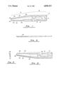
- FIG. 1 is a front view of an electrosurgical scalpel blade in accordance with the present invention
- FIG. 2 is a rear view of the blade of FIG. 1;
- FIG. 3 is a distal end view of the blade of FIG. 1;
- FIG. 4 is a bottom view of the blade of FIG. 1.
- the electrosurgical blade of the present invention is indicated generally by numeral 10 and is seen to comprise a ceramic substrate 12 which is preferably a material exhibiting a relatively high volume resistivity over a substantial temperature range, with silicon nitride ceramic being preferred.
- the ceramic blank or substrate 12 has an integrally joined distal working portion identified by the bracket 14 and a handle receiving portion identified by bracket 16. That is to say, the electrosurgical blade 10 is intended to be inserted into a handle (not shown) which may, for example, be of the type described in a co-pending application of Marc D. Noerenberg, et al, Ser. No. 56,434, filed June 1, 1987, and entitled "ELECTRO-SURGICAL BLADE".
- the handle is effective to firmly grip the blade 10 and to apply the requisite electrical voltages to the conductive patterns or traces formed on the blade, the configuration of which are yet to be described.
- the handle incorporates a piezoelectric crystal which is arranged to abut the handle receiving portion 16 of the blade to impart high frequency vibrations thereto whereby cavitation results, aiding in preventing the buildup of burned tissue and other debris on the blade.
- the handle receiving portion 16 is generally rectangular, except for a registration notch 18 formed inwardly from the lower edge thereof.
- the working portion 14 of the blade includes a working edge 20 and an opposed edge 22 which converges toward the working edge 20 but terminating at a blunt distal tip 24.
- the working edge 20 of the blade is ground to provide a beveled edge as indicated by numeral 26.
- the blunt tip 24 is also beveled as indicated by numeral 28.
- the silicon nitride substrate heretofore described is also provided with a pattern of metallization in the form of conductive traces which may be realized using known hybrid circuit techniques.
- refractory metals such as tungsten, titanium, nickel, molybdenum, manganese and alloys thereof may be applied in accordance with a predetermined pattern utilizing silk screening techniques or vacuum sputtering through a suitable mask.
- first and second conductive traces 30 and 32 are made to extend parallel to the working edge 20 on opposed side surfaces of the silicon nitride ceramic substrate so as to be spaced from one another solely by the thickness of the substrate at the beveled working edge, at least over the working portion 14 of the blade.
- the strips or traces 30 and 32 also extend substantially across the handle receiving portion 16 of the blade with the pattern including a conductive pad area 34 and 36 of a substantially greater width than the remainder.
- conductive traces 38 and 40 Extending along the opposed edge 22 on either side of the substrate are conductive traces 38 and 40 which are formed from the same materials and using the same processes used in adhering the traces 30 and 32 to the silicon nitride substrate 12. Both the traces 38 and 40 extend generally the full length of the blade's working portion 14 and handle receiving portion 16. This allows electrical connections to be made through the handle to an electrosurgical generator.
- the connector in the handle also electrically joins traces 38 and 40 in common.
- the working portion 14 of the blade may, as an option, be provided with a coating of a suitable insulating material such as silicon dioxide.
- This coating is identified by numeral 42 and, when employed, is present on both sides of the blade so as to substantially cover the ceramic substrate 12 and the metallized tracings 30-32 and 38-40. Subsequently, the working edge 20 will typically be back-ground to expose the underlying metallization along the beveled edge 20 thereof. In a like fashion, a portion of the coating 42 along the opposed edge 22 of the blade is ground away, as at 44 and 46, to expose the underlying metallized traces 38 and 40. The coating layer 42 is also removed over a small area 48 of the tip 24 to expose the underlying conductive trace 40 and 38 at that location.
- the blade shown in FIG. 1 When in use, the blade shown in FIG. 1 is inserted into a suitable handle (not shown) whereby RF voltages may selectively be applied between the traces 30 and 32 extending along the beveled edge of the working portion 14 of the blade. Because of the very close spacing between the conductive strips which are separated only by the thickness dimension of the substrate at the beveled working edge 20, a relatively high current density exists along that working edge so that when the scalpel blade is brought into contact with tissue to be cut, a relatively large current will flow through the tissue causing the cells coming in contact with the blade to burst and, as the blade is drawn along the tissue, an incision is thereby created.
- an RF voltage can be created between the traces 30 and 32, to produce cutting and between traces 32 and 30-40 to produce coagulation. Because of the relatively large spacings between these traces, the current density at the tip 24 is considerably lower than that existing across the traces 30 and 32 during a cutting operation. When the tip portion 24 is touched against a severed blood vessel, sufficient heat is created to dehydrate the tissue, resulting in coagulation and clotting of the severed vessel.
- the substrate exhibits a relatively high volume resistivity over a significant temperature range.
- silicon nitride is used as the substrate material
- the substrate exhibits a relatively high volume resistivity over a significant temperature range.
- the material exhibited a resistance in excess of 200 megohms up to a temperature of 500° C. while maintaining a resistance of 3.6 megohms at a temperature of 800° C.
- problems of thermal runaway are greatly minimized. That is to say, the material does not break down significantly so as to cause such high parasitic currents to flow through the ceramic which would further deteriorate the resistance characteristics of the material, at least at nominal operating voltages, power levels and arcing conditions.
Abstract
Description
Claims (10)
Priority Applications (1)
| Application Number | Priority Date | Filing Date | Title |
|---|---|---|---|
| US07/229,432 US4850353A (en) | 1988-08-08 | 1988-08-08 | Silicon nitride electrosurgical blade |
Applications Claiming Priority (1)
| Application Number | Priority Date | Filing Date | Title |
|---|---|---|---|
| US07/229,432 US4850353A (en) | 1988-08-08 | 1988-08-08 | Silicon nitride electrosurgical blade |
Publications (1)
| Publication Number | Publication Date |
|---|---|
| US4850353A true US4850353A (en) | 1989-07-25 |
Family
ID=22861229
Family Applications (1)
| Application Number | Title | Priority Date | Filing Date |
|---|---|---|---|
| US07/229,432 Expired - Fee Related US4850353A (en) | 1988-08-08 | 1988-08-08 | Silicon nitride electrosurgical blade |
Country Status (1)
| Country | Link |
|---|---|
| US (1) | US4850353A (en) |
Cited By (137)
| Publication number | Priority date | Publication date | Assignee | Title |
|---|---|---|---|---|
| US5013312A (en) * | 1990-03-19 | 1991-05-07 | Everest Medical Corporation | Bipolar scalpel for harvesting internal mammary artery |
| US5064994A (en) * | 1989-10-18 | 1991-11-12 | Urban Paul L | Fast-heating high-temperature fiber cutting tool |
| WO1992014514A1 (en) * | 1991-02-13 | 1992-09-03 | Applied Medical Resources, Inc. | Surgical trocar |
| US5196009A (en) * | 1991-09-11 | 1993-03-23 | Kirwan Jr Lawrence T | Non-sticking electrosurgical device having nickel tips |
| WO1994005226A1 (en) * | 1992-09-09 | 1994-03-17 | Medical Coatings Corporation | Electro-surgical instrument and method of fabrication |
| US5308311A (en) * | 1992-05-01 | 1994-05-03 | Robert F. Shaw | Electrically heated surgical blade and methods of making |
| US5382247A (en) * | 1994-01-21 | 1995-01-17 | Valleylab Inc. | Technique for electrosurgical tips and method of manufacture and use |
| US5451224A (en) * | 1992-02-27 | 1995-09-19 | G2 Design Limited | Apparatus for radio frequency bipolar electrosurgery |
| US5496317A (en) * | 1993-05-04 | 1996-03-05 | Gyrus Medical Limited | Laparoscopic surgical instrument |
| US5573534A (en) * | 1993-05-06 | 1996-11-12 | United States Surgical Corporation | Bipolar electrosurgical instruments |
| US5579583A (en) * | 1992-09-22 | 1996-12-03 | Micromed, Incorporated | Microfabricated blades |
| US5599347A (en) * | 1991-02-13 | 1997-02-04 | Applied Medical Resources Corporation | Surgical trocar with cutoff circuit |
| US5658281A (en) * | 1995-12-04 | 1997-08-19 | Valleylab Inc | Bipolar electrosurgical scissors and method of manufacture |
| US5728089A (en) * | 1993-06-04 | 1998-03-17 | The Regents Of The University Of California | Microfabricated structure to be used in surgery |
| US5766166A (en) * | 1995-03-07 | 1998-06-16 | Enable Medical Corporation | Bipolar Electrosurgical scissors |
| US5779701A (en) * | 1995-04-27 | 1998-07-14 | Symbiosis Corporation | Bipolar endoscopic surgical scissor blades and instrument incorporating the same |
| US5807395A (en) * | 1993-08-27 | 1998-09-15 | Medtronic, Inc. | Method and apparatus for RF ablation and hyperthermia |
| US5830214A (en) * | 1994-11-08 | 1998-11-03 | Heartport, Inc. | Fluid-evacuating electrosurgical device |
| US5893846A (en) * | 1996-05-15 | 1999-04-13 | Symbiosis Corp. | Ceramic coated endoscopic scissor blades and a method of making the same |
| EP0912141A1 (en) * | 1996-06-12 | 1999-05-06 | ITI Medical Technologies, Inc. | Electrosurgical instrument with conductive ceramic or cermet and method of making same |
| US5944715A (en) | 1996-06-20 | 1999-08-31 | Gyrus Medical Limited | Electrosurgical instrument |
| US5979700A (en) * | 1997-12-30 | 1999-11-09 | Kimberly-Clark Worldwide, Inc. | Clip lift for tissue dispensing system |
| US5980518A (en) * | 1995-10-27 | 1999-11-09 | Carr; William N. | Microcautery surgical tool |
| US5984919A (en) * | 1991-02-13 | 1999-11-16 | Applied Medical Resources Corporation | Surgical trocar |
| US6004319A (en) | 1995-06-23 | 1999-12-21 | Gyrus Medical Limited | Electrosurgical instrument |
| US6013076A (en) | 1996-01-09 | 2000-01-11 | Gyrus Medical Limited | Electrosurgical instrument |
| US6015406A (en) | 1996-01-09 | 2000-01-18 | Gyrus Medical Limited | Electrosurgical instrument |
| US6027501A (en) | 1995-06-23 | 2000-02-22 | Gyrus Medical Limited | Electrosurgical instrument |
| US6041679A (en) * | 1991-04-04 | 2000-03-28 | Symbiosis Corporation | Endoscopic end effectors constructed from a combination of conductive and non-conductive materials and useful for selective endoscopic cautery |
| US6063081A (en) * | 1995-02-22 | 2000-05-16 | Medtronic, Inc. | Fluid-assisted electrocautery device |
| US6070444A (en) * | 1999-03-31 | 2000-06-06 | Sherwood Services Ag | Method of mass manufacturing coated electrosurgical electrodes |
| US6090106A (en) | 1996-01-09 | 2000-07-18 | Gyrus Medical Limited | Electrosurgical instrument |
| US6093186A (en) | 1996-12-20 | 2000-07-25 | Gyrus Medical Limited | Electrosurgical generator and system |
| US6179837B1 (en) | 1995-03-07 | 2001-01-30 | Enable Medical Corporation | Bipolar electrosurgical scissors |
| US6183467B1 (en) * | 1996-09-06 | 2001-02-06 | Xomed, Inc. | Package for removable device tips |
| US6210405B1 (en) | 1996-06-20 | 2001-04-03 | Gyrus Medical Limited | Under water treatment |
| US6261286B1 (en) | 1995-06-23 | 2001-07-17 | Gyrus Medical Limited | Electrosurgical generator and system |
| US6277114B1 (en) | 1998-04-03 | 2001-08-21 | Gyrus Medical Limited | Electrode assembly for an electrosurical instrument |
| US6391029B1 (en) | 1995-03-07 | 2002-05-21 | Enable Medical Corporation | Bipolar electrosurgical scissors |
| US20020116022A1 (en) * | 2000-07-25 | 2002-08-22 | Lebouitz Kyle S. | Method of making a cutting instrument having integrated sensors |
| US6447511B1 (en) | 1994-12-13 | 2002-09-10 | Symbiosis Corporation | Bipolar endoscopic surgical scissor blades and instrument incorporating the same |
| US6464701B1 (en) | 1995-03-07 | 2002-10-15 | Enable Medical Corporation | Bipolar electrosurgical scissors |
| US20020169392A1 (en) * | 2001-05-01 | 2002-11-14 | Csaba Truckai | Electrosurgical working end and method for obtaining tissue samples for biopsy |
| US20030055417A1 (en) * | 2001-09-19 | 2003-03-20 | Csaba Truckai | Surgical system for applying ultrasonic energy to tissue |
| US20030055360A1 (en) * | 2001-09-05 | 2003-03-20 | Zeleznik Matthew A. | Minimally invasive sensing system for measuring rigidity of anatomical matter |
| US20030069579A1 (en) * | 2001-09-13 | 2003-04-10 | Csaba Truckai | Electrosurgical working end with resistive gradient electrodes |
| US6565561B1 (en) | 1996-06-20 | 2003-05-20 | Cyrus Medical Limited | Electrosurgical instrument |
| US20030144652A1 (en) * | 2001-11-09 | 2003-07-31 | Baker James A. | Electrosurgical instrument |
| US20030171748A1 (en) * | 2001-10-22 | 2003-09-11 | Sciogen Llc | Electrosurgical instrument and method of use |
| US6623501B2 (en) * | 2000-04-05 | 2003-09-23 | Therasense, Inc. | Reusable ceramic skin-piercing device |
| US20030199870A1 (en) * | 2001-10-22 | 2003-10-23 | Csaba Truckai | Jaw structure for electrosurgical instrument |
| US20030199165A1 (en) * | 2002-03-11 | 2003-10-23 | Becton, Dickinson And Company | System and method for the manufacture of surgical blades |
| US20030216732A1 (en) * | 2002-05-20 | 2003-11-20 | Csaba Truckai | Medical instrument with thermochromic or piezochromic surface indicators |
| US20030220637A1 (en) * | 2001-10-22 | 2003-11-27 | Csaba Truckai | Electrosurgical working end with replaceable cartridges |
| US20040002745A1 (en) * | 2002-06-27 | 2004-01-01 | Gyrus Medical Limited. | Electrosurgical system |
| EP1374788A1 (en) | 2002-06-27 | 2004-01-02 | Gyrus Medical Limited | Electrosurgical system |
| US6747218B2 (en) | 2002-09-20 | 2004-06-08 | Sherwood Services Ag | Electrosurgical haptic switch including snap dome and printed circuit stepped contact array |
| US20040116979A1 (en) * | 2002-10-01 | 2004-06-17 | Surgrx | Electrosurgical instrument and method of use |
| US20040153055A1 (en) * | 2000-12-15 | 2004-08-05 | Tyco Healthcare Group Lp | Electrosurgical electrode shroud |
| US6780180B1 (en) | 1995-06-23 | 2004-08-24 | Gyrus Medical Limited | Electrosurgical instrument |
| US20040199161A1 (en) * | 2003-02-14 | 2004-10-07 | Surgrx, Inc., A Delaware Corporation | Electrosurgical probe and method of use |
| US20040215185A1 (en) * | 2001-10-18 | 2004-10-28 | Csaba Truckai | Electrosurgical working end for cotrolled energy delivery |
| US20050113824A1 (en) * | 2003-11-20 | 2005-05-26 | Sartor Joe D. | Electrosurgical pencil with improved controls |
| US20050133017A1 (en) * | 2003-12-23 | 2005-06-23 | Scialdone John A. | Double-pit outdoor grill |
| WO2005055846A1 (en) | 2003-12-09 | 2005-06-23 | Gyrus Group Plc | A surgical instrument |
| US20050159745A1 (en) * | 2004-01-16 | 2005-07-21 | Surgrx, Inc. | Electrosurgical instrument with replaceable cartridge |
| US20050155955A1 (en) * | 2003-03-10 | 2005-07-21 | Daskal Vadim M. | Method for reducing glare and creating matte finish of controlled density on a silicon surface |
| US20050171535A1 (en) * | 2001-10-22 | 2005-08-04 | Surgrx, Inc. | Electrosurgical instrument and method of use |
| US6929644B2 (en) | 2001-10-22 | 2005-08-16 | Surgrx Inc. | Electrosurgical jaw structure for controlled energy delivery |
| US20050188548A1 (en) * | 2002-03-11 | 2005-09-01 | Daskal Vadim M. | Silicon blades for surgical and non-surgical use |
| US20050267464A1 (en) * | 2001-10-18 | 2005-12-01 | Surgrx, Inc. | Electrosurgical instrument and method of use |
| US20050266680A1 (en) * | 2004-04-30 | 2005-12-01 | Daskal Vadim M | Methods of fabricating complex blade geometries from silicon wafers and strengthening blade geometries |
| US20050283151A1 (en) * | 2004-06-18 | 2005-12-22 | Gyrus Medical Limited | Surgical instrument |
| US20060000823A1 (en) * | 2003-11-19 | 2006-01-05 | Surgrx, Inc. | Polymer compositions exhibiting a PTC property and methods of fabrication |
| US7011657B2 (en) | 2001-10-22 | 2006-03-14 | Surgrx, Inc. | Jaw structure for electrosurgical instrument and method of use |
| US7083619B2 (en) | 2001-10-22 | 2006-08-01 | Surgrx, Inc. | Electrosurgical instrument and method of use |
| US20060212030A1 (en) * | 2005-03-16 | 2006-09-21 | Mcgaffigan Thomas H | Integrated metalized ceramic heating element for use in a tissue cutting and sealing device |
| US20060235378A1 (en) * | 2005-04-18 | 2006-10-19 | Sherwood Services Ag | Slider control for ablation handset |
| US7156844B2 (en) | 2003-11-20 | 2007-01-02 | Sherwood Services Ag | Electrosurgical pencil with improved controls |
| US7189233B2 (en) | 2001-10-22 | 2007-03-13 | Surgrx, Inc. | Electrosurgical instrument |
| US7235072B2 (en) | 2003-02-20 | 2007-06-26 | Sherwood Services Ag | Motion detector for controlling electrosurgical output |
| US7241294B2 (en) | 2003-11-19 | 2007-07-10 | Sherwood Services Ag | Pistol grip electrosurgical pencil with manual aspirator/irrigator and methods of using the same |
| US7244257B2 (en) | 2002-11-05 | 2007-07-17 | Sherwood Services Ag | Electrosurgical pencil having a single button variable control |
| US20070187874A1 (en) * | 2003-09-17 | 2007-08-16 | Daskal Vadim M | System and method for creating linear and non-linear trenches in silicon and other crystalline materials with a router |
| US20080027427A1 (en) * | 2006-07-27 | 2008-01-31 | Applied Medical Resources Corporation | Bipolar electrosurgical scissors |
| US7393354B2 (en) | 2002-07-25 | 2008-07-01 | Sherwood Services Ag | Electrosurgical pencil with drag sensing capability |
| US7422588B2 (en) | 1995-02-22 | 2008-09-09 | Medtronic, Inc. | Pen-type electrosurgical instrument |
| US20090007436A1 (en) * | 2003-03-10 | 2009-01-08 | Daskal Vadim M | Silicon blades for surgical and non-surgical use |
| US7500974B2 (en) | 2005-06-28 | 2009-03-10 | Covidien Ag | Electrode with rotatably deployable sheath |
| US7503917B2 (en) | 2003-11-20 | 2009-03-17 | Covidien Ag | Electrosurgical pencil with improved controls |
| US7828794B2 (en) | 2005-08-25 | 2010-11-09 | Covidien Ag | Handheld electrosurgical apparatus for controlling operating room equipment |
| US7879033B2 (en) | 2003-11-20 | 2011-02-01 | Covidien Ag | Electrosurgical pencil with advanced ES controls |
| US20110054461A1 (en) * | 2009-09-02 | 2011-03-03 | Tyco Healthcare Group Lp | Electrosurgical Electrode with Insulative Coating |
| US7955331B2 (en) | 2004-03-12 | 2011-06-07 | Ethicon Endo-Surgery, Inc. | Electrosurgical instrument and method of use |
| EP2392281A1 (en) * | 2010-04-20 | 2011-12-07 | OOO "Novye Energetischeskie | Electro-surgical bipolar scalpel |
| US8075558B2 (en) | 2002-04-30 | 2011-12-13 | Surgrx, Inc. | Electrosurgical instrument and method |
| US8162937B2 (en) | 2008-06-27 | 2012-04-24 | Tyco Healthcare Group Lp | High volume fluid seal for electrosurgical handpiece |
| US8231620B2 (en) | 2009-02-10 | 2012-07-31 | Tyco Healthcare Group Lp | Extension cutting blade |
| US8235987B2 (en) | 2007-12-05 | 2012-08-07 | Tyco Healthcare Group Lp | Thermal penetration and arc length controllable electrosurgical pencil |
| US8292888B2 (en) | 2001-04-20 | 2012-10-23 | Tyco Healthcare Group Lp | Bipolar or ultrasonic surgical device |
| EP2524663A1 (en) * | 2011-05-16 | 2012-11-21 | Tyco Healthcare Group, LP | Electrosurgical instrument with jaws and with means for imparting mechanical perturbations to a jaw |
| US8500727B2 (en) | 2008-05-13 | 2013-08-06 | Megadyne Medical Products, Inc. | Methods, systems, and devices for performing electrosurgical procedures |
| US8506565B2 (en) | 2007-08-23 | 2013-08-13 | Covidien Lp | Electrosurgical device with LED adapter |
| US20130226176A1 (en) * | 2010-11-04 | 2013-08-29 | Ralf Kuehner | Electrode Device of an Electrosurgical Instrument |
| US8551088B2 (en) | 2008-03-31 | 2013-10-08 | Applied Medical Resources Corporation | Electrosurgical system |
| US8591509B2 (en) | 2008-03-31 | 2013-11-26 | Covidien Lp | Electrosurgical pencil including improved controls |
| US8597292B2 (en) | 2008-03-31 | 2013-12-03 | Covidien Lp | Electrosurgical pencil including improved controls |
| US8636733B2 (en) | 2008-03-31 | 2014-01-28 | Covidien Lp | Electrosurgical pencil including improved controls |
| US8668688B2 (en) | 2006-05-05 | 2014-03-11 | Covidien Ag | Soft tissue RF transection and resection device |
| US9039694B2 (en) | 2010-10-22 | 2015-05-26 | Just Right Surgical, Llc | RF generator system for surgical vessel sealing |
| US9144455B2 (en) | 2010-06-07 | 2015-09-29 | Just Right Surgical, Llc | Low power tissue sealing device and method |
| US9198724B2 (en) | 2011-04-08 | 2015-12-01 | Covidien Lp | Microwave tissue dissection and coagulation |
| US20150366613A1 (en) * | 2014-06-20 | 2015-12-24 | Perseon Corporation | Ablation probe with metalized ceramic component |
| USD748259S1 (en) | 2014-12-29 | 2016-01-26 | Applied Medical Resources Corporation | Electrosurgical instrument |
| US9320563B2 (en) | 2010-10-01 | 2016-04-26 | Applied Medical Resources Corporation | Electrosurgical instruments and connections thereto |
| CN106308889A (en) * | 2016-10-27 | 2017-01-11 | 江苏怡龙医疗科技有限公司 | Intelligent ultrasonic scalpel for tumor treatment |
| WO2017192901A1 (en) * | 2016-05-05 | 2017-11-09 | I.C. Medical, Inc. | Electrosurgery blade and electrosurgery blade assembly |
| US20180092692A1 (en) * | 2016-10-05 | 2018-04-05 | I.C. Medical, Inc. | Ultrapolar telescopic electrosurgery pencil |
| US20180256243A1 (en) * | 2017-03-06 | 2018-09-13 | I.C. Medical, Inc. | Ultrapolar electrosurgery blade and ultrapolar electrosurgery blade assembly with conductive cutting edges and top and bottom conductive surfaces |
| US10149713B2 (en) | 2014-05-16 | 2018-12-11 | Applied Medical Resources Corporation | Electrosurgical system |
| CN110053325A (en) * | 2019-05-09 | 2019-07-26 | 费凛 | A kind of anti-sticking mucous layer on electric knife surface |
| JP2019521796A (en) * | 2016-07-15 | 2019-08-08 | アイ.シー. メディカル, インコーポレイテッド | Superpolar electrosurgical blade and superpolar electrosurgical pencil |
| US10420603B2 (en) | 2014-12-23 | 2019-09-24 | Applied Medical Resources Corporation | Bipolar electrosurgical sealer and divider |
| US10702334B2 (en) | 2016-07-15 | 2020-07-07 | I.C. Medical, Inc. | Ultrapolar telescopic electrosurgery pencil |
| US10716587B2 (en) | 2014-06-13 | 2020-07-21 | Surgis Medical Llc | Surgical device with light |
| US10722299B2 (en) | 2016-07-15 | 2020-07-28 | I.C. Medical, Inc. | Ultrapolar electrosurgery blade and ultrapolar electrosurgery pencil |
| US10779878B2 (en) | 2015-11-25 | 2020-09-22 | Gyrus Acmi, Inc. | Thermal control devices for electrosurgical instruments |
| US10792095B2 (en) | 2017-03-05 | 2020-10-06 | I.C. Medical, Inc. | Monopolar electrosurgery pencil with argon beam capability |
| US10792092B2 (en) | 2014-05-30 | 2020-10-06 | Applied Medical Resources Corporation | Electrosurgical seal and dissection systems |
| USD904611S1 (en) | 2018-10-10 | 2020-12-08 | Bolder Surgical, Llc | Jaw design for a surgical instrument |
| US11166757B2 (en) * | 2017-03-13 | 2021-11-09 | I.C. Medical, Inc. | Ultrapolar electrosurgery blade and ultrapolar electrosurgery blade assembly with conductive contacts on top, bottom, sides and cutting edge of blade |
| US11399888B2 (en) | 2019-08-14 | 2022-08-02 | Covidien Lp | Bipolar pencil |
| US11564732B2 (en) | 2019-12-05 | 2023-01-31 | Covidien Lp | Tensioning mechanism for bipolar pencil |
| US11604026B2 (en) | 2019-03-14 | 2023-03-14 | Terumo Bct Biotechnologies, Llc | Lyophilization loading tray assembly and system |
| US11634257B2 (en) | 2017-10-09 | 2023-04-25 | Terumo Bct Biotechnologies, Llc | Lyophilization container and method of using same |
| US11696796B2 (en) | 2018-11-16 | 2023-07-11 | Applied Medical Resources Corporation | Electrosurgical system |
| US11864812B2 (en) | 2018-09-05 | 2024-01-09 | Applied Medical Resources Corporation | Electrosurgical generator control system |
Citations (7)
| Publication number | Priority date | Publication date | Assignee | Title |
|---|---|---|---|---|
| US4074718A (en) * | 1976-03-17 | 1978-02-21 | Valleylab, Inc. | Electrosurgical instrument |
| US4161950A (en) * | 1975-08-01 | 1979-07-24 | The United States Of America As Represented By The United States Department Of Energy | Electrosurgical knife |
| US4202337A (en) * | 1977-06-14 | 1980-05-13 | Concept, Inc. | Bipolar electrosurgical knife |
| US4232676A (en) * | 1978-11-16 | 1980-11-11 | Corning Glass Works | Surgical cutting instrument |
| US4248231A (en) * | 1978-11-16 | 1981-02-03 | Corning Glass Works | Surgical cutting instrument |
| US4314559A (en) * | 1979-12-12 | 1982-02-09 | Corning Glass Works | Nonstick conductive coating |
| US4802476A (en) * | 1987-06-01 | 1989-02-07 | Everest Medical Corporation | Electro-surgical instrument |
-
1988
- 1988-08-08 US US07/229,432 patent/US4850353A/en not_active Expired - Fee Related
Patent Citations (7)
| Publication number | Priority date | Publication date | Assignee | Title |
|---|---|---|---|---|
| US4161950A (en) * | 1975-08-01 | 1979-07-24 | The United States Of America As Represented By The United States Department Of Energy | Electrosurgical knife |
| US4074718A (en) * | 1976-03-17 | 1978-02-21 | Valleylab, Inc. | Electrosurgical instrument |
| US4202337A (en) * | 1977-06-14 | 1980-05-13 | Concept, Inc. | Bipolar electrosurgical knife |
| US4232676A (en) * | 1978-11-16 | 1980-11-11 | Corning Glass Works | Surgical cutting instrument |
| US4248231A (en) * | 1978-11-16 | 1981-02-03 | Corning Glass Works | Surgical cutting instrument |
| US4314559A (en) * | 1979-12-12 | 1982-02-09 | Corning Glass Works | Nonstick conductive coating |
| US4802476A (en) * | 1987-06-01 | 1989-02-07 | Everest Medical Corporation | Electro-surgical instrument |
Cited By (268)
| Publication number | Priority date | Publication date | Assignee | Title |
|---|---|---|---|---|
| US5064994A (en) * | 1989-10-18 | 1991-11-12 | Urban Paul L | Fast-heating high-temperature fiber cutting tool |
| US5013312A (en) * | 1990-03-19 | 1991-05-07 | Everest Medical Corporation | Bipolar scalpel for harvesting internal mammary artery |
| US5344420A (en) * | 1991-02-13 | 1994-09-06 | Applied Medical Resources Corporation | Surgical trocar |
| US5599347A (en) * | 1991-02-13 | 1997-02-04 | Applied Medical Resources Corporation | Surgical trocar with cutoff circuit |
| WO1992014514A1 (en) * | 1991-02-13 | 1992-09-03 | Applied Medical Resources, Inc. | Surgical trocar |
| US5984919A (en) * | 1991-02-13 | 1999-11-16 | Applied Medical Resources Corporation | Surgical trocar |
| US6041679A (en) * | 1991-04-04 | 2000-03-28 | Symbiosis Corporation | Endoscopic end effectors constructed from a combination of conductive and non-conductive materials and useful for selective endoscopic cautery |
| US5196009A (en) * | 1991-09-11 | 1993-03-23 | Kirwan Jr Lawrence T | Non-sticking electrosurgical device having nickel tips |
| US5451224A (en) * | 1992-02-27 | 1995-09-19 | G2 Design Limited | Apparatus for radio frequency bipolar electrosurgery |
| US5308311A (en) * | 1992-05-01 | 1994-05-03 | Robert F. Shaw | Electrically heated surgical blade and methods of making |
| WO1994005226A1 (en) * | 1992-09-09 | 1994-03-17 | Medical Coatings Corporation | Electro-surgical instrument and method of fabrication |
| US5562659A (en) * | 1992-09-09 | 1996-10-08 | Materials Conversion Corp. | Electro-surgical instrument and method of fabrication |
| US5827275A (en) * | 1992-09-09 | 1998-10-27 | Medicor Corporation | Electro-surgical instrument and fabrication method |
| US5579583A (en) * | 1992-09-22 | 1996-12-03 | Micromed, Incorporated | Microfabricated blades |
| US5496317A (en) * | 1993-05-04 | 1996-03-05 | Gyrus Medical Limited | Laparoscopic surgical instrument |
| US5573534A (en) * | 1993-05-06 | 1996-11-12 | United States Surgical Corporation | Bipolar electrosurgical instruments |
| US5728089A (en) * | 1993-06-04 | 1998-03-17 | The Regents Of The University Of California | Microfabricated structure to be used in surgery |
| US5807395A (en) * | 1993-08-27 | 1998-09-15 | Medtronic, Inc. | Method and apparatus for RF ablation and hyperthermia |
| US5382247A (en) * | 1994-01-21 | 1995-01-17 | Valleylab Inc. | Technique for electrosurgical tips and method of manufacture and use |
| US5830214A (en) * | 1994-11-08 | 1998-11-03 | Heartport, Inc. | Fluid-evacuating electrosurgical device |
| US8114074B1 (en) | 1994-12-13 | 2012-02-14 | Boston Scientific Miami Corporation | Bipolar endoscopic surgical scissor blades and instrument incorporating the same |
| US20040199160A1 (en) * | 1994-12-13 | 2004-10-07 | Symbiosis Corporation | Bipolar endoscopic surgical scissor blades and instrument incorporating the same |
| US7063697B2 (en) | 1994-12-13 | 2006-06-20 | Symbiosis Corporation | Bipolar endoscopic surgical scissor blades and instrument incorporating the same |
| US20060195084A1 (en) * | 1994-12-13 | 2006-08-31 | Boston Scientific Miami Corporation | Bipolar endoscopic surgical scissor blades and instrument incorporating the same |
| US8409197B2 (en) | 1994-12-13 | 2013-04-02 | Boston Scientific Miami Corporation | Methods of cutting tissue using a medical instrument |
| US6447511B1 (en) | 1994-12-13 | 2002-09-10 | Symbiosis Corporation | Bipolar endoscopic surgical scissor blades and instrument incorporating the same |
| US7422588B2 (en) | 1995-02-22 | 2008-09-09 | Medtronic, Inc. | Pen-type electrosurgical instrument |
| US6063081A (en) * | 1995-02-22 | 2000-05-16 | Medtronic, Inc. | Fluid-assisted electrocautery device |
| US7794460B2 (en) | 1995-02-22 | 2010-09-14 | Medtronic, Inc. | Method of ablating tissue |
| US6391029B1 (en) | 1995-03-07 | 2002-05-21 | Enable Medical Corporation | Bipolar electrosurgical scissors |
| US6350264B1 (en) | 1995-03-07 | 2002-02-26 | Enable Medical Corporation | Bipolar electrosurgical scissors |
| US6464701B1 (en) | 1995-03-07 | 2002-10-15 | Enable Medical Corporation | Bipolar electrosurgical scissors |
| US6179837B1 (en) | 1995-03-07 | 2001-01-30 | Enable Medical Corporation | Bipolar electrosurgical scissors |
| US5766166A (en) * | 1995-03-07 | 1998-06-16 | Enable Medical Corporation | Bipolar Electrosurgical scissors |
| US5779701A (en) * | 1995-04-27 | 1998-07-14 | Symbiosis Corporation | Bipolar endoscopic surgical scissor blades and instrument incorporating the same |
| US6364877B1 (en) | 1995-06-23 | 2002-04-02 | Gyrus Medical Limited | Electrosurgical generator and system |
| US6416509B1 (en) | 1995-06-23 | 2002-07-09 | Gyrus Medical Limited | Electrosurgical generator and system |
| US6261286B1 (en) | 1995-06-23 | 2001-07-17 | Gyrus Medical Limited | Electrosurgical generator and system |
| US6780180B1 (en) | 1995-06-23 | 2004-08-24 | Gyrus Medical Limited | Electrosurgical instrument |
| US6174308B1 (en) | 1995-06-23 | 2001-01-16 | Gyrus Medical Limited | Electrosurgical instrument |
| US6027501A (en) | 1995-06-23 | 2000-02-22 | Gyrus Medical Limited | Electrosurgical instrument |
| US6056746A (en) | 1995-06-23 | 2000-05-02 | Gyrus Medical Limited | Electrosurgical instrument |
| US6004319A (en) | 1995-06-23 | 1999-12-21 | Gyrus Medical Limited | Electrosurgical instrument |
| US6306134B1 (en) | 1995-06-23 | 2001-10-23 | Gyrus Medical Limited | Electrosurgical generator and system |
| US6293942B1 (en) | 1995-06-23 | 2001-09-25 | Gyrus Medical Limited | Electrosurgical generator method |
| US5980518A (en) * | 1995-10-27 | 1999-11-09 | Carr; William N. | Microcautery surgical tool |
| US5658281A (en) * | 1995-12-04 | 1997-08-19 | Valleylab Inc | Bipolar electrosurgical scissors and method of manufacture |
| US6013076A (en) | 1996-01-09 | 2000-01-11 | Gyrus Medical Limited | Electrosurgical instrument |
| US6015406A (en) | 1996-01-09 | 2000-01-18 | Gyrus Medical Limited | Electrosurgical instrument |
| US6090106A (en) | 1996-01-09 | 2000-07-18 | Gyrus Medical Limited | Electrosurgical instrument |
| US6234178B1 (en) | 1996-01-09 | 2001-05-22 | Gyrus Medical Limited | Electrosurgical instrument |
| US5893846A (en) * | 1996-05-15 | 1999-04-13 | Symbiosis Corp. | Ceramic coated endoscopic scissor blades and a method of making the same |
| EP0912141A1 (en) * | 1996-06-12 | 1999-05-06 | ITI Medical Technologies, Inc. | Electrosurgical instrument with conductive ceramic or cermet and method of making same |
| EP0912141A4 (en) * | 1996-06-12 | 1999-12-15 | Iti Medical Technologies Inc | Electrosurgical instrument with conductive ceramic or cermet and method of making same |
| US5925039A (en) * | 1996-06-12 | 1999-07-20 | Iti Medical Technologies, Inc. | Electrosurgical instrument with conductive ceramic or cermet and method of making same |
| US5944715A (en) | 1996-06-20 | 1999-08-31 | Gyrus Medical Limited | Electrosurgical instrument |
| US6565561B1 (en) | 1996-06-20 | 2003-05-20 | Cyrus Medical Limited | Electrosurgical instrument |
| US6482202B1 (en) | 1996-06-20 | 2002-11-19 | Gyrus Medical Limited | Under water treatment |
| US6210405B1 (en) | 1996-06-20 | 2001-04-03 | Gyrus Medical Limited | Under water treatment |
| US6183467B1 (en) * | 1996-09-06 | 2001-02-06 | Xomed, Inc. | Package for removable device tips |
| US6358241B1 (en) | 1996-09-06 | 2002-03-19 | Medtronic Xomed, Inc. | Package for removable device tips |
| US6960200B2 (en) | 1996-09-06 | 2005-11-01 | Medtronic Xomed, Inc. | Package for removable device tips |
| US6093186A (en) | 1996-12-20 | 2000-07-25 | Gyrus Medical Limited | Electrosurgical generator and system |
| US5979700A (en) * | 1997-12-30 | 1999-11-09 | Kimberly-Clark Worldwide, Inc. | Clip lift for tissue dispensing system |
| US6277114B1 (en) | 1998-04-03 | 2001-08-21 | Gyrus Medical Limited | Electrode assembly for an electrosurical instrument |
| US6070444A (en) * | 1999-03-31 | 2000-06-06 | Sherwood Services Ag | Method of mass manufacturing coated electrosurgical electrodes |
| US9662514B2 (en) | 1999-06-02 | 2017-05-30 | Covidien Lp | Bipolar or ultrasonic surgical device |
| US6623501B2 (en) * | 2000-04-05 | 2003-09-23 | Therasense, Inc. | Reusable ceramic skin-piercing device |
| US6972199B2 (en) | 2000-07-25 | 2005-12-06 | Verimetra, Inc. | Method of making a cutting instrument having integrated sensors |
| US20020116022A1 (en) * | 2000-07-25 | 2002-08-22 | Lebouitz Kyle S. | Method of making a cutting instrument having integrated sensors |
| US6494882B1 (en) | 2000-07-25 | 2002-12-17 | Verimetra, Inc. | Cutting instrument having integrated sensors |
| US20040153055A1 (en) * | 2000-12-15 | 2004-08-05 | Tyco Healthcare Group Lp | Electrosurgical electrode shroud |
| US20060189977A1 (en) * | 2000-12-15 | 2006-08-24 | Charles Allen | Electrosurgical electrode shroud |
| US20050273098A1 (en) * | 2000-12-15 | 2005-12-08 | Charles Allen | Electrosurgical electrode shroud |
| US6986768B2 (en) | 2000-12-15 | 2006-01-17 | Sherwood Services Ag | Electrosurgical electrode shroud |
| US7582244B2 (en) | 2000-12-15 | 2009-09-01 | Covidien Ag | Electrosurgical electrode shroud |
| US7060064B2 (en) | 2000-12-15 | 2006-06-13 | Sherwood Services Ag | Electrosurgical electrode shroud |
| US8845665B2 (en) | 2001-04-20 | 2014-09-30 | Covidien Lp | Bipolar or ultrasonic surgical device |
| US8292888B2 (en) | 2001-04-20 | 2012-10-23 | Tyco Healthcare Group Lp | Bipolar or ultrasonic surgical device |
| US8523890B2 (en) | 2001-04-20 | 2013-09-03 | Covidien Lp | Bipolar or ultrasonic surgical device |
| US20020169392A1 (en) * | 2001-05-01 | 2002-11-14 | Csaba Truckai | Electrosurgical working end and method for obtaining tissue samples for biopsy |
| US6913579B2 (en) | 2001-05-01 | 2005-07-05 | Surgrx, Inc. | Electrosurgical working end and method for obtaining tissue samples for biopsy |
| US20030055360A1 (en) * | 2001-09-05 | 2003-03-20 | Zeleznik Matthew A. | Minimally invasive sensing system for measuring rigidity of anatomical matter |
| US20030069579A1 (en) * | 2001-09-13 | 2003-04-10 | Csaba Truckai | Electrosurgical working end with resistive gradient electrodes |
| US6802843B2 (en) | 2001-09-13 | 2004-10-12 | Csaba Truckai | Electrosurgical working end with resistive gradient electrodes |
| US6773409B2 (en) | 2001-09-19 | 2004-08-10 | Surgrx Llc | Surgical system for applying ultrasonic energy to tissue |
| US20030055417A1 (en) * | 2001-09-19 | 2003-03-20 | Csaba Truckai | Surgical system for applying ultrasonic energy to tissue |
| US20040215185A1 (en) * | 2001-10-18 | 2004-10-28 | Csaba Truckai | Electrosurgical working end for cotrolled energy delivery |
| US7070597B2 (en) | 2001-10-18 | 2006-07-04 | Surgrx, Inc. | Electrosurgical working end for controlled energy delivery |
| US20050267464A1 (en) * | 2001-10-18 | 2005-12-01 | Surgrx, Inc. | Electrosurgical instrument and method of use |
| US20030220637A1 (en) * | 2001-10-22 | 2003-11-27 | Csaba Truckai | Electrosurgical working end with replaceable cartridges |
| US7083619B2 (en) | 2001-10-22 | 2006-08-01 | Surgrx, Inc. | Electrosurgical instrument and method of use |
| US20070129728A1 (en) * | 2001-10-22 | 2007-06-07 | Surgrx, Inc. | Electrosurgical instrument |
| US6929644B2 (en) | 2001-10-22 | 2005-08-16 | Surgrx Inc. | Electrosurgical jaw structure for controlled energy delivery |
| US7189233B2 (en) | 2001-10-22 | 2007-03-13 | Surgrx, Inc. | Electrosurgical instrument |
| US7186253B2 (en) | 2001-10-22 | 2007-03-06 | Surgrx, Inc. | Electrosurgical jaw structure for controlled energy delivery |
| US9149326B2 (en) | 2001-10-22 | 2015-10-06 | Ethicon Endo-Surgery, Inc. | Electrosurgical instrument and method |
| US7381209B2 (en) | 2001-10-22 | 2008-06-03 | Surgrx, Inc. | Electrosurgical instrument |
| US6905497B2 (en) | 2001-10-22 | 2005-06-14 | Surgrx, Inc. | Jaw structure for electrosurgical instrument |
| US7981113B2 (en) | 2001-10-22 | 2011-07-19 | Surgrx, Inc. | Electrosurgical instrument |
| US20080188851A1 (en) * | 2001-10-22 | 2008-08-07 | Surgrx, Inc. | Electrosurgical instrument |
| US7354440B2 (en) | 2001-10-22 | 2008-04-08 | Surgrx, Inc. | Electrosurgical instrument and method of use |
| US7011657B2 (en) | 2001-10-22 | 2006-03-14 | Surgrx, Inc. | Jaw structure for electrosurgical instrument and method of use |
| US7041102B2 (en) | 2001-10-22 | 2006-05-09 | Surgrx, Inc. | Electrosurgical working end with replaceable cartridges |
| US7112201B2 (en) | 2001-10-22 | 2006-09-26 | Surgrx Inc. | Electrosurgical instrument and method of use |
| US20030171748A1 (en) * | 2001-10-22 | 2003-09-11 | Sciogen Llc | Electrosurgical instrument and method of use |
| US20050171535A1 (en) * | 2001-10-22 | 2005-08-04 | Surgrx, Inc. | Electrosurgical instrument and method of use |
| US20050192568A1 (en) * | 2001-10-22 | 2005-09-01 | Surgrx, Inc. | Electrosurgical jaw structure for controlled energy delivery |
| US20030199870A1 (en) * | 2001-10-22 | 2003-10-23 | Csaba Truckai | Jaw structure for electrosurgical instrument |
| US20030144652A1 (en) * | 2001-11-09 | 2003-07-31 | Baker James A. | Electrosurgical instrument |
| US6926716B2 (en) | 2001-11-09 | 2005-08-09 | Surgrx Inc. | Electrosurgical instrument |
| US20050188548A1 (en) * | 2002-03-11 | 2005-09-01 | Daskal Vadim M. | Silicon blades for surgical and non-surgical use |
| US7105103B2 (en) | 2002-03-11 | 2006-09-12 | Becton, Dickinson And Company | System and method for the manufacture of surgical blades |
| US20030199165A1 (en) * | 2002-03-11 | 2003-10-23 | Becton, Dickinson And Company | System and method for the manufacture of surgical blades |
| US8409462B2 (en) | 2002-03-11 | 2013-04-02 | Beaver-Visitec International (Us), Inc. | System and method for the manufacture of surgical blades |
| US7906437B2 (en) | 2002-03-11 | 2011-03-15 | Beaver-Visitec International (Us), Inc. | System and method for the manufacture of surgical blades |
| US20110192819A1 (en) * | 2002-03-11 | 2011-08-11 | Beaver-Vistec International, Inc. | System and method for the manufacture of surgical blades |
| US7387742B2 (en) | 2002-03-11 | 2008-06-17 | Becton, Dickinson And Company | Silicon blades for surgical and non-surgical use |
| US8075558B2 (en) | 2002-04-30 | 2011-12-13 | Surgrx, Inc. | Electrosurgical instrument and method |
| US20030216732A1 (en) * | 2002-05-20 | 2003-11-20 | Csaba Truckai | Medical instrument with thermochromic or piezochromic surface indicators |
| EP1374788A1 (en) | 2002-06-27 | 2004-01-02 | Gyrus Medical Limited | Electrosurgical system |
| US20040002745A1 (en) * | 2002-06-27 | 2004-01-01 | Gyrus Medical Limited. | Electrosurgical system |
| US7220260B2 (en) | 2002-06-27 | 2007-05-22 | Gyrus Medical Limited | Electrosurgical system |
| US7901401B2 (en) | 2002-06-27 | 2011-03-08 | Gyrus Medical Limited | Electrosurgical system |
| US7393354B2 (en) | 2002-07-25 | 2008-07-01 | Sherwood Services Ag | Electrosurgical pencil with drag sensing capability |
| US7621909B2 (en) | 2002-07-25 | 2009-11-24 | Covidien Ag | Electrosurgical pencil with drag sensing capability |
| US8016824B2 (en) | 2002-07-25 | 2011-09-13 | Covidien Ag | Electrosurgical pencil with drag sensing capability |
| US6747218B2 (en) | 2002-09-20 | 2004-06-08 | Sherwood Services Ag | Electrosurgical haptic switch including snap dome and printed circuit stepped contact array |
| US20040116979A1 (en) * | 2002-10-01 | 2004-06-17 | Surgrx | Electrosurgical instrument and method of use |
| US7087054B2 (en) | 2002-10-01 | 2006-08-08 | Surgrx, Inc. | Electrosurgical instrument and method of use |
| US7244257B2 (en) | 2002-11-05 | 2007-07-17 | Sherwood Services Ag | Electrosurgical pencil having a single button variable control |
| US8128622B2 (en) | 2002-11-05 | 2012-03-06 | Covidien Ag | Electrosurgical pencil having a single button variable control |
| US20040199161A1 (en) * | 2003-02-14 | 2004-10-07 | Surgrx, Inc., A Delaware Corporation | Electrosurgical probe and method of use |
| US7169146B2 (en) | 2003-02-14 | 2007-01-30 | Surgrx, Inc. | Electrosurgical probe and method of use |
| US7235072B2 (en) | 2003-02-20 | 2007-06-26 | Sherwood Services Ag | Motion detector for controlling electrosurgical output |
| US7955327B2 (en) | 2003-02-20 | 2011-06-07 | Covidien Ag | Motion detector for controlling electrosurgical output |
| US20050155955A1 (en) * | 2003-03-10 | 2005-07-21 | Daskal Vadim M. | Method for reducing glare and creating matte finish of controlled density on a silicon surface |
| US20090007436A1 (en) * | 2003-03-10 | 2009-01-08 | Daskal Vadim M | Silicon blades for surgical and non-surgical use |
| US7785485B2 (en) | 2003-09-17 | 2010-08-31 | Becton, Dickinson And Company | System and method for creating linear and non-linear trenches in silicon and other crystalline materials with a router |
| US20070187874A1 (en) * | 2003-09-17 | 2007-08-16 | Daskal Vadim M | System and method for creating linear and non-linear trenches in silicon and other crystalline materials with a router |
| US20060000823A1 (en) * | 2003-11-19 | 2006-01-05 | Surgrx, Inc. | Polymer compositions exhibiting a PTC property and methods of fabrication |
| US7309849B2 (en) | 2003-11-19 | 2007-12-18 | Surgrx, Inc. | Polymer compositions exhibiting a PTC property and methods of fabrication |
| US7241294B2 (en) | 2003-11-19 | 2007-07-10 | Sherwood Services Ag | Pistol grip electrosurgical pencil with manual aspirator/irrigator and methods of using the same |
| US7503917B2 (en) | 2003-11-20 | 2009-03-17 | Covidien Ag | Electrosurgical pencil with improved controls |
| US7156844B2 (en) | 2003-11-20 | 2007-01-02 | Sherwood Services Ag | Electrosurgical pencil with improved controls |
| US7156842B2 (en) | 2003-11-20 | 2007-01-02 | Sherwood Services Ag | Electrosurgical pencil with improved controls |
| US7879033B2 (en) | 2003-11-20 | 2011-02-01 | Covidien Ag | Electrosurgical pencil with advanced ES controls |
| US8449540B2 (en) | 2003-11-20 | 2013-05-28 | Covidien Ag | Electrosurgical pencil with improved controls |
| US20050113824A1 (en) * | 2003-11-20 | 2005-05-26 | Sartor Joe D. | Electrosurgical pencil with improved controls |
| US7959633B2 (en) | 2003-11-20 | 2011-06-14 | Covidien Ag | Electrosurgical pencil with improved controls |
| WO2005055846A1 (en) | 2003-12-09 | 2005-06-23 | Gyrus Group Plc | A surgical instrument |
| US20050133017A1 (en) * | 2003-12-23 | 2005-06-23 | Scialdone John A. | Double-pit outdoor grill |
| US7632269B2 (en) | 2004-01-16 | 2009-12-15 | Ethicon Endo-Surgery, Inc. | Electrosurgical instrument with replaceable cartridge |
| US20050159745A1 (en) * | 2004-01-16 | 2005-07-21 | Surgrx, Inc. | Electrosurgical instrument with replaceable cartridge |
| US7955331B2 (en) | 2004-03-12 | 2011-06-07 | Ethicon Endo-Surgery, Inc. | Electrosurgical instrument and method of use |
| US20050266680A1 (en) * | 2004-04-30 | 2005-12-01 | Daskal Vadim M | Methods of fabricating complex blade geometries from silicon wafers and strengthening blade geometries |
| US7396484B2 (en) | 2004-04-30 | 2008-07-08 | Becton, Dickinson And Company | Methods of fabricating complex blade geometries from silicon wafers and strengthening blade geometries |
| AU2005253762B2 (en) * | 2004-06-18 | 2011-03-31 | Gyrus Medical Limited | A surgical instrument |
| US7150748B2 (en) | 2004-06-18 | 2006-12-19 | Gyrus Medical Limited | Bipolar coagulating instrument |
| CN100443062C (en) * | 2004-06-18 | 2008-12-17 | 佳乐医疗设备有限公司 | Surgical instrument |
| WO2005122936A1 (en) * | 2004-06-18 | 2005-12-29 | Gyrus Medical Limited | A surgical instrument |
| US20050283151A1 (en) * | 2004-06-18 | 2005-12-22 | Gyrus Medical Limited | Surgical instrument |
| AU2005253762C1 (en) * | 2004-06-18 | 2011-08-11 | Gyrus Medical Limited | A surgical instrument |
| US7771424B2 (en) | 2005-03-16 | 2010-08-10 | Starion Instruments | Integrated metalized ceramic heating element for use in a tissue cutting and sealing device |
| WO2006102018A2 (en) | 2005-03-16 | 2006-09-28 | Starion Instruments Corporation | Integrated metalized ceramic heating element for use in a tissue cutting and sealing device |
| US20090198224A1 (en) * | 2005-03-16 | 2009-08-06 | Starion Instruments | Integrated Metalized Ceramic Heating Element for Use in a Tissue Cutting and Sealing Device |
| US8192432B2 (en) | 2005-03-16 | 2012-06-05 | Microline Surgical, Inc. | Integrated metalized ceramic heating element for use in a tissue cutting and sealing device |
| US20060212030A1 (en) * | 2005-03-16 | 2006-09-21 | Mcgaffigan Thomas H | Integrated metalized ceramic heating element for use in a tissue cutting and sealing device |
| US20060235378A1 (en) * | 2005-04-18 | 2006-10-19 | Sherwood Services Ag | Slider control for ablation handset |
| US8460289B2 (en) | 2005-06-28 | 2013-06-11 | Covidien Ag | Electrode with rotatably deployable sheath |
| US8100902B2 (en) | 2005-06-28 | 2012-01-24 | Covidien Ag | Electrode with rotatably deployable sheath |
| US7500974B2 (en) | 2005-06-28 | 2009-03-10 | Covidien Ag | Electrode with rotatably deployable sheath |
| US20090138012A1 (en) * | 2005-06-28 | 2009-05-28 | Sherwood Services Ag | Electrode with Rotatably Deployable Sheath |
| US7828794B2 (en) | 2005-08-25 | 2010-11-09 | Covidien Ag | Handheld electrosurgical apparatus for controlling operating room equipment |
| US8668688B2 (en) | 2006-05-05 | 2014-03-11 | Covidien Ag | Soft tissue RF transection and resection device |
| US7419490B2 (en) | 2006-07-27 | 2008-09-02 | Applied Medical Resources Corporation | Bipolar electrosurgical scissors |
| US20080027427A1 (en) * | 2006-07-27 | 2008-01-31 | Applied Medical Resources Corporation | Bipolar electrosurgical scissors |
| US8597293B2 (en) | 2006-07-27 | 2013-12-03 | Applied Medical Resources Corporation | Bipolar electrosurgical scissors |
| US8226649B2 (en) | 2006-07-27 | 2012-07-24 | Applied Medical Resources Corporation | Bipolar electrosurgical scissors |
| US20090005779A1 (en) * | 2006-07-27 | 2009-01-01 | Applied Medical Resources Corporation | Bipolar electrosurgical scissors |
| US8506565B2 (en) | 2007-08-23 | 2013-08-13 | Covidien Lp | Electrosurgical device with LED adapter |
| US8235987B2 (en) | 2007-12-05 | 2012-08-07 | Tyco Healthcare Group Lp | Thermal penetration and arc length controllable electrosurgical pencil |
| US8945124B2 (en) | 2007-12-05 | 2015-02-03 | Covidien Lp | Thermal penetration and arc length controllable electrosurgical pencil |
| US8663219B2 (en) | 2008-03-31 | 2014-03-04 | Covidien Lp | Electrosurgical pencil including improved controls |
| US8663218B2 (en) | 2008-03-31 | 2014-03-04 | Covidien Lp | Electrosurgical pencil including improved controls |
| US11660136B2 (en) | 2008-03-31 | 2023-05-30 | Applied Medical Resources Corporation | Electrosurgical system |
| US8551088B2 (en) | 2008-03-31 | 2013-10-08 | Applied Medical Resources Corporation | Electrosurgical system |
| US8562598B2 (en) | 2008-03-31 | 2013-10-22 | Applied Medical Resources Corporation | Electrosurgical system |
| US8568411B2 (en) | 2008-03-31 | 2013-10-29 | Applied Medical Resources Corporation | Electrosurgical system |
| US8579894B2 (en) | 2008-03-31 | 2013-11-12 | Applied Medical Resources Corporation | Electrosurgical system |
| US8591509B2 (en) | 2008-03-31 | 2013-11-26 | Covidien Lp | Electrosurgical pencil including improved controls |
| US9198720B2 (en) | 2008-03-31 | 2015-12-01 | Covidien Lp | Electrosurgical pencil including improved controls |
| US8597292B2 (en) | 2008-03-31 | 2013-12-03 | Covidien Lp | Electrosurgical pencil including improved controls |
| US8632536B2 (en) | 2008-03-31 | 2014-01-21 | Covidien Lp | Electrosurgical pencil including improved controls |
| US8636733B2 (en) | 2008-03-31 | 2014-01-28 | Covidien Lp | Electrosurgical pencil including improved controls |
| US10888371B2 (en) | 2008-03-31 | 2021-01-12 | Applied Medical Resources Corporation | Electrosurgical system |
| US9566108B2 (en) | 2008-03-31 | 2017-02-14 | Applied Medical Resources Corporation | Electrosurgical system |
| US10342604B2 (en) | 2008-03-31 | 2019-07-09 | Applied Medical Resources Corporation | Electrosurgical system |
| US8915910B2 (en) | 2008-03-31 | 2014-12-23 | Applied Medical Resources Corporation | Electrosurgical system |
| US8500727B2 (en) | 2008-05-13 | 2013-08-06 | Megadyne Medical Products, Inc. | Methods, systems, and devices for performing electrosurgical procedures |
| US8162937B2 (en) | 2008-06-27 | 2012-04-24 | Tyco Healthcare Group Lp | High volume fluid seal for electrosurgical handpiece |
| US8231620B2 (en) | 2009-02-10 | 2012-07-31 | Tyco Healthcare Group Lp | Extension cutting blade |
| US8398625B2 (en) | 2009-09-02 | 2013-03-19 | Covidien Lp | Electrosurgical electrode with insulative coating |
| US20110054461A1 (en) * | 2009-09-02 | 2011-03-03 | Tyco Healthcare Group Lp | Electrosurgical Electrode with Insulative Coating |
| DE202010017918U1 (en) | 2010-04-20 | 2013-02-05 | Ooo "Novye Energeticheskie Technologii" | Electrosurgical bipolar scalpel |
| EP2392281A1 (en) * | 2010-04-20 | 2011-12-07 | OOO "Novye Energetischeskie | Electro-surgical bipolar scalpel |
| US9144455B2 (en) | 2010-06-07 | 2015-09-29 | Just Right Surgical, Llc | Low power tissue sealing device and method |
| US10166064B2 (en) | 2010-06-07 | 2019-01-01 | Just Right Surgical, Llc | Low-power tissue sealing device and method |
| US11399884B2 (en) | 2010-06-07 | 2022-08-02 | Bolder Surgical, Llc | Low power tissue sealing device and method |
| US9962222B2 (en) | 2010-10-01 | 2018-05-08 | Applied Medical Resources Corporation | Electrosurgical instruments and connections thereto |
| US9320563B2 (en) | 2010-10-01 | 2016-04-26 | Applied Medical Resources Corporation | Electrosurgical instruments and connections thereto |
| US11864823B2 (en) | 2010-10-01 | 2024-01-09 | Applied Medical Resources Corporation | Electrosurgical instruments and connections thereto |
| US10874452B2 (en) | 2010-10-01 | 2020-12-29 | Applied Medical Resources Corporation | Electrosurgical instruments and connections thereto |
| US9649149B2 (en) | 2010-10-22 | 2017-05-16 | Just Right Surgical, Llc | RF generator system for surgical vessel sealing |
| US10342599B2 (en) | 2010-10-22 | 2019-07-09 | Just Right Surgical, Llc | RF generator system for surgical vessel sealing |
| US9039694B2 (en) | 2010-10-22 | 2015-05-26 | Just Right Surgical, Llc | RF generator system for surgical vessel sealing |
| US9622815B2 (en) * | 2010-11-04 | 2017-04-18 | Erbe Elektromedizin Gmbh | Electrode device of an electrosurgical instrument |
| US20130226176A1 (en) * | 2010-11-04 | 2013-08-29 | Ralf Kuehner | Electrode Device of an Electrosurgical Instrument |
| US9198724B2 (en) | 2011-04-08 | 2015-12-01 | Covidien Lp | Microwave tissue dissection and coagulation |
| US10799290B2 (en) | 2011-04-08 | 2020-10-13 | Covidien Lp | Microwave tissue dissection and coagulation |
| US10098697B2 (en) | 2011-04-08 | 2018-10-16 | Covidien Lp | Microwave tissue dissection and coagulation |
| US9265568B2 (en) | 2011-05-16 | 2016-02-23 | Coviden Lp | Destruction of vessel walls for energy-based vessel sealing enhancement |
| EP2524663A1 (en) * | 2011-05-16 | 2012-11-21 | Tyco Healthcare Group, LP | Electrosurgical instrument with jaws and with means for imparting mechanical perturbations to a jaw |
| US10149713B2 (en) | 2014-05-16 | 2018-12-11 | Applied Medical Resources Corporation | Electrosurgical system |
| US11672589B2 (en) | 2014-05-16 | 2023-06-13 | Applied Medical Resources Corporation | Electrosurgical system |
| US10792092B2 (en) | 2014-05-30 | 2020-10-06 | Applied Medical Resources Corporation | Electrosurgical seal and dissection systems |
| US10716587B2 (en) | 2014-06-13 | 2020-07-21 | Surgis Medical Llc | Surgical device with light |
| US20150366613A1 (en) * | 2014-06-20 | 2015-12-24 | Perseon Corporation | Ablation probe with metalized ceramic component |
| US11540871B2 (en) | 2014-12-23 | 2023-01-03 | Applied Medical Resources Corporation | Bipolar electrosurgical sealer and divider |
| US10420603B2 (en) | 2014-12-23 | 2019-09-24 | Applied Medical Resources Corporation | Bipolar electrosurgical sealer and divider |
| USD748259S1 (en) | 2014-12-29 | 2016-01-26 | Applied Medical Resources Corporation | Electrosurgical instrument |
| EP3821839A1 (en) | 2015-11-25 | 2021-05-19 | Gyrus ACMI, Inc. d/b/a Olympus Surgical Technologies America | Thermal control devices for electrosurgical instruments |
| US10779878B2 (en) | 2015-11-25 | 2020-09-22 | Gyrus Acmi, Inc. | Thermal control devices for electrosurgical instruments |
| US11684411B2 (en) | 2015-11-25 | 2023-06-27 | Gyrus Acmi, Inc. | Thermal control devices for electrosurgical instruments |
| US11903631B2 (en) | 2016-05-05 | 2024-02-20 | I.C. Medical, Inc. | Electrosurgery blade and electrosurgery blade assembly |
| WO2017192901A1 (en) * | 2016-05-05 | 2017-11-09 | I.C. Medical, Inc. | Electrosurgery blade and electrosurgery blade assembly |
| US11291491B2 (en) | 2016-05-05 | 2022-04-05 | I.C. Medical, Inc. | Electrosurgery blade and electrosurgery blade assembly |
| US11534237B2 (en) | 2016-07-15 | 2022-12-27 | I.C. Medical, Inc. | Ultrapolar electrosurgery blade and ultrapolar electrosurgery pencil |
| US10702334B2 (en) | 2016-07-15 | 2020-07-07 | I.C. Medical, Inc. | Ultrapolar telescopic electrosurgery pencil |
| JP2019521796A (en) * | 2016-07-15 | 2019-08-08 | アイ.シー. メディカル, インコーポレイテッド | Superpolar electrosurgical blade and superpolar electrosurgical pencil |
| US11103303B2 (en) | 2016-07-15 | 2021-08-31 | I.C. Medical, Inc. | Ultrapolar telescopic electrosurgery pencil |
| JP7344553B2 (en) | 2016-07-15 | 2023-09-14 | アイ.シー. メディカル, インコーポレイテッド | Electrosurgical blades and electrosurgical pencils |
| US10722299B2 (en) | 2016-07-15 | 2020-07-28 | I.C. Medical, Inc. | Ultrapolar electrosurgery blade and ultrapolar electrosurgery pencil |
| US20180092692A1 (en) * | 2016-10-05 | 2018-04-05 | I.C. Medical, Inc. | Ultrapolar telescopic electrosurgery pencil |
| JP2019528988A (en) * | 2016-10-05 | 2019-10-17 | アイ.シー. メディカル, インコーポレイテッド | Superpolar electrosurgical blade, superpolar electrosurgical pencil, and telescopic electrosurgical pencil used in ESU monopolar and bipolar modes |
| US11564740B2 (en) * | 2016-10-05 | 2023-01-31 | I.C. Medical, Inc. | Ultrapolar telescopic electrosurgery pencil |
| CN106308889B (en) * | 2016-10-27 | 2019-01-01 | 江苏怡龙医疗科技有限公司 | A kind of Intelligence Ultrasound scalpel for oncotherapy |
| CN106308889A (en) * | 2016-10-27 | 2017-01-11 | 江苏怡龙医疗科技有限公司 | Intelligent ultrasonic scalpel for tumor treatment |
| US10792095B2 (en) | 2017-03-05 | 2020-10-06 | I.C. Medical, Inc. | Monopolar electrosurgery pencil with argon beam capability |
| US11246651B2 (en) | 2017-03-05 | 2022-02-15 | I.C. Medical, Inc. | Monopolar telescopic electrosurgery pencil with argon beam capability |
| US11109907B2 (en) * | 2017-03-06 | 2021-09-07 | I.C. Medical, Inc. | Ultrapolar electrosurgery blade and ultrapolar electrosurgery blade assembly with conductive cutting edges and top and bottom conductive surfaces |
| AU2018230707B2 (en) * | 2017-03-06 | 2023-03-30 | I.C. Medical, Inc. | Ultrapolar electrosurgery blade and ultrapolar electrosurgery blade assembly with conductive cutting edges and top and bottom conductive surfaces |
| US20180256243A1 (en) * | 2017-03-06 | 2018-09-13 | I.C. Medical, Inc. | Ultrapolar electrosurgery blade and ultrapolar electrosurgery blade assembly with conductive cutting edges and top and bottom conductive surfaces |
| US11166757B2 (en) * | 2017-03-13 | 2021-11-09 | I.C. Medical, Inc. | Ultrapolar electrosurgery blade and ultrapolar electrosurgery blade assembly with conductive contacts on top, bottom, sides and cutting edge of blade |
| US11903629B2 (en) | 2017-03-13 | 2024-02-20 | I.C. Medical, Inc. | Ultrapolar electrosurgery blade and ultrapolar electrosurgery blade assembly with conductive contacts on top, bottom, sides and cutting edge of blade |
| US11634257B2 (en) | 2017-10-09 | 2023-04-25 | Terumo Bct Biotechnologies, Llc | Lyophilization container and method of using same |
| US11864812B2 (en) | 2018-09-05 | 2024-01-09 | Applied Medical Resources Corporation | Electrosurgical generator control system |
| USD904611S1 (en) | 2018-10-10 | 2020-12-08 | Bolder Surgical, Llc | Jaw design for a surgical instrument |
| US11696796B2 (en) | 2018-11-16 | 2023-07-11 | Applied Medical Resources Corporation | Electrosurgical system |
| US11609043B2 (en) | 2019-03-14 | 2023-03-21 | Terumo Bct Biotechnologies, Llc | Lyophilization container fill fixture, system and method of use |
| US11740019B2 (en) | 2019-03-14 | 2023-08-29 | Terumo Bct Biotechnologies, Llc | Lyophilization loading tray assembly and system |
| US11747082B2 (en) | 2019-03-14 | 2023-09-05 | Terumo Bct Biotechnologies, Llc | Multi-part lyophilization container and method of use |
| US11609042B2 (en) | 2019-03-14 | 2023-03-21 | Terumo Bct Biotechnologies, Llc | Multi-part lyophilization container and method of use |
| US11815311B2 (en) | 2019-03-14 | 2023-11-14 | Terumo Bct Biotechnologies, Llc | Lyophilization container fill fixture, system and method of use |
| US11604026B2 (en) | 2019-03-14 | 2023-03-14 | Terumo Bct Biotechnologies, Llc | Lyophilization loading tray assembly and system |
| CN110053325A (en) * | 2019-05-09 | 2019-07-26 | 费凛 | A kind of anti-sticking mucous layer on electric knife surface |
| US11399888B2 (en) | 2019-08-14 | 2022-08-02 | Covidien Lp | Bipolar pencil |
| US11564732B2 (en) | 2019-12-05 | 2023-01-31 | Covidien Lp | Tensioning mechanism for bipolar pencil |
Similar Documents
| Publication | Publication Date | Title |
|---|---|---|
| US4850353A (en) | Silicon nitride electrosurgical blade | |
| US4862890A (en) | Electrosurgical spatula blade with ceramic substrate | |
| JP4313205B2 (en) | Surgical instruments | |
| US4958539A (en) | Method of making an electrosurgical spatula blade | |
| US7211084B2 (en) | Surgical system | |
| EP3363396B1 (en) | Apparatus for electrosurgery comprising superposed electrodes with curved distal parts | |
| US4074718A (en) | Electrosurgical instrument | |
| KR100322052B1 (en) | Electric field concentrated electrosurgical electrode | |
| US4232676A (en) | Surgical cutting instrument | |
| US7004939B2 (en) | Electrosurgical apparatus | |
| US20160242836A1 (en) | Apparatus, System and Method for Excision of Soft Tissue | |
| US4228800A (en) | Bipolar electrosurgical knife | |
| US5658281A (en) | Bipolar electrosurgical scissors and method of manufacture | |
| US20040068307A1 (en) | Surgical instrument | |
| EP1407719A2 (en) | A surgical instrument | |
| JP7158742B2 (en) | An electrosurgical blade assembly including an electrosurgical blade having a conductive cutting edge and upper and lower conductive surfaces | |
| EP0280798B1 (en) | Electrosurgery surgical instrument | |
| JP7176763B2 (en) | A superpolar electrosurgical blade with conductive contacts on the top, bottom, sides and cutting edge of the blade | |
| JP2001518344A (en) | Electric field concentration type electrosurgical electrode | |
| JP7205909B2 (en) | Monopolar Electrosurgical Blades and Electrosurgical Blade Assemblies | |
| JP2019526368A (en) | Monopolar electrosurgical blade and electrosurgical blade assembly | |
| JP3010265B2 (en) | Vascular coagulation hemostasis device | |
| AU784494B2 (en) | EXPLORAR P.C.E.- Plasma cutting and hemostatic electrode for electrosurgery | |
| US20230346456A1 (en) | Electrosurgical blade with minimally exposed edge, alternative to coated blade | |
| JPH0524778B2 (en) |
Legal Events
| Date | Code | Title | Description |
|---|---|---|---|
| AS | Assignment |
Owner name: EVEREST MEDICAL CORPORATION, 6601 SHINGLE CREEK, P Free format text: ASSIGNMENT OF ASSIGNORS INTEREST.;ASSIGNORS:STASZ, PETER;SOLBERG, JEFFREY J.;GRABINGER, SCOTT R.;REEL/FRAME:004961/0610 Effective date: 19880727 Owner name: EVEREST MEDICAL CORPORATION, A CORP. OF MN, MINNES Free format text: ASSIGNMENT OF ASSIGNORS INTEREST;ASSIGNORS:STASZ, PETER;SOLBERG, JEFFREY J.;GRABINGER, SCOTT R.;REEL/FRAME:004961/0610 Effective date: 19880727 |
|
| AS | Assignment |
Owner name: AVA/MARINER ASSOCIATES, MINNESOTA Free format text: SECURITY INTEREST;ASSIGNOR:EVEREST MEDICAL CORPORATION;REEL/FRAME:005253/0632 Effective date: 19900110 |
|
| AS | Assignment |
Owner name: EVEREST MEDICAL CORPORATION, A MN CORP. Free format text: RELEASED BY SECURED PARTY;ASSIGNOR:AVA/MARINER ASSOCIATES;REEL/FRAME:005278/0359 Effective date: 19900402 |
|
| AS | Assignment |
Owner name: ST. PAUL FIRE AND MARINE INSURANCE COMPANY Free format text: MORTGAGE;ASSIGNOR:EVEREST MEDICAL CORPORATION;REEL/FRAME:006046/0226 Effective date: 19920218 |
|
| FPAY | Fee payment |
Year of fee payment: 4 |
|
| AS | Assignment |
Owner name: ST. PAUL FIRE AND MARINE INSURANCE COMPANY, MINNES Free format text: MORTGAGE;ASSIGNOR:EVEREST MEDICAL CORPORATION;REEL/FRAME:006893/0711 Effective date: 19940218 |
|
| REMI | Maintenance fee reminder mailed | ||
| LAPS | Lapse for failure to pay maintenance fees | ||
| FP | Expired due to failure to pay maintenance fee |
Effective date: 19970730 |
|
| AS | Assignment |
Owner name: GYRUS MEDICAL, INC., MINNESOTA Free format text: CHANGE OF NAME;ASSIGNOR:EVEREST MEDICAL CORPORATION;REEL/FRAME:012802/0936 Effective date: 20010405 |
|
| AS | Assignment |
Owner name: THE GOVERNOR AND COMPANY OF THE BANK OF SCOTLAND, Free format text: ASSIGNMENT OF ASSIGNORS INTEREST;ASSIGNOR:GYRUS MEDICAL, INC.;REEL/FRAME:016408/0631 Effective date: 20050721 |
|
| AS | Assignment |
Owner name: THE GOVERNOR AND COMPANY OF THE BANK OF SCOTLAND, Free format text: CORRECTIVE ASSIGNMENT TO CORRECT THE NATURE OF DOCUMENT ERRONEOUSLY RECORDED AS AN ASSIGNMENT TO RECORDATION OF GRANT OF SECURITY INTEREST PREVIOUSLY RECORDED ON REEL 016408 FRAME 0631;ASSIGNOR:GYRUS MEDICAL, INC.;REEL/FRAME:016418/0162 Effective date: 20050721 |
|
| AS | Assignment |
Owner name: GYRUS ACMI, INC., MASSACHUSETTS Free format text: ASSIGNMENT OF ASSIGNORS INTEREST;ASSIGNOR:BANK OF SCOTLAND;REEL/FRAME:030422/0113 Effective date: 20130419 |
|
| STCH | Information on status: patent discontinuation |
Free format text: PATENT EXPIRED DUE TO NONPAYMENT OF MAINTENANCE FEES UNDER 37 CFR 1.362 |