US4851069A - Process for making tissue-absorbent particle laminates - Google Patents
Process for making tissue-absorbent particle laminates Download PDFInfo
- Publication number
- US4851069A US4851069A US06/622,640 US62264084A US4851069A US 4851069 A US4851069 A US 4851069A US 62264084 A US62264084 A US 62264084A US 4851069 A US4851069 A US 4851069A
- Authority
- US
- United States
- Prior art keywords
- tissue
- particles
- roller
- tissues
- absorptive
- Prior art date
- Legal status (The legal status is an assumption and is not a legal conclusion. Google has not performed a legal analysis and makes no representation as to the accuracy of the status listed.)
- Expired - Fee Related
Links
- 239000002245 particle Substances 0.000 title claims abstract description 72
- 238000000034 method Methods 0.000 title claims abstract description 32
- 230000008569 process Effects 0.000 title claims abstract description 32
- 239000002250 absorbent Substances 0.000 title claims abstract description 31
- 230000002745 absorbent Effects 0.000 claims abstract description 28
- 239000007788 liquid Substances 0.000 claims abstract description 22
- 239000000853 adhesive Substances 0.000 claims abstract description 4
- 230000001070 adhesive effect Effects 0.000 claims abstract description 4
- 238000010521 absorption reaction Methods 0.000 claims abstract description 3
- 230000001105 regulatory effect Effects 0.000 claims 1
- 230000008859 change Effects 0.000 description 7
- 238000004519 manufacturing process Methods 0.000 description 7
- 239000000843 powder Substances 0.000 description 5
- 238000010438 heat treatment Methods 0.000 description 4
- 239000011236 particulate material Substances 0.000 description 4
- 229920001971 elastomer Polymers 0.000 description 3
- XLYOFNOQVPJJNP-UHFFFAOYSA-N water Substances O XLYOFNOQVPJJNP-UHFFFAOYSA-N 0.000 description 3
- 229910000831 Steel Inorganic materials 0.000 description 2
- 230000009286 beneficial effect Effects 0.000 description 2
- 230000007423 decrease Effects 0.000 description 2
- 230000000694 effects Effects 0.000 description 2
- 239000000806 elastomer Substances 0.000 description 2
- 239000000835 fiber Substances 0.000 description 2
- 230000001788 irregular Effects 0.000 description 2
- 239000000463 material Substances 0.000 description 2
- 230000007246 mechanism Effects 0.000 description 2
- 239000010959 steel Substances 0.000 description 2
- 238000004804 winding Methods 0.000 description 2
- PQUXFUBNSYCQAL-UHFFFAOYSA-N 1-(2,3-difluorophenyl)ethanone Chemical compound CC(=O)C1=CC=CC(F)=C1F PQUXFUBNSYCQAL-UHFFFAOYSA-N 0.000 description 1
- 229920001410 Microfiber Polymers 0.000 description 1
- 229910052773 Promethium Inorganic materials 0.000 description 1
- 238000013459 approach Methods 0.000 description 1
- 230000005540 biological transmission Effects 0.000 description 1
- 210000001124 body fluid Anatomy 0.000 description 1
- 239000010839 body fluid Substances 0.000 description 1
- 239000003638 chemical reducing agent Substances 0.000 description 1
- 239000003795 chemical substances by application Substances 0.000 description 1
- 239000002131 composite material Substances 0.000 description 1
- 238000010276 construction Methods 0.000 description 1
- 238000001514 detection method Methods 0.000 description 1
- 238000004049 embossing Methods 0.000 description 1
- 230000006872 improvement Effects 0.000 description 1
- 239000003658 microfiber Substances 0.000 description 1
- 230000008520 organization Effects 0.000 description 1
- 229920000058 polyacrylate Polymers 0.000 description 1
- VQMWBBYLQSCNPO-UHFFFAOYSA-N promethium atom Chemical compound [Pm] VQMWBBYLQSCNPO-UHFFFAOYSA-N 0.000 description 1
- 229940047670 sodium acrylate Drugs 0.000 description 1
- 239000000758 substrate Substances 0.000 description 1
- 150000005846 sugar alcohols Polymers 0.000 description 1
- 230000008016 vaporization Effects 0.000 description 1
- 238000009834 vaporization Methods 0.000 description 1
Images

Classifications
-
- B—PERFORMING OPERATIONS; TRANSPORTING
- B32—LAYERED PRODUCTS
- B32B—LAYERED PRODUCTS, i.e. PRODUCTS BUILT-UP OF STRATA OF FLAT OR NON-FLAT, e.g. CELLULAR OR HONEYCOMB, FORM
- B32B29/00—Layered products comprising a layer of paper or cardboard
- B32B29/04—Layered products comprising a layer of paper or cardboard next to a particulate layer
-
- A—HUMAN NECESSITIES
- A61—MEDICAL OR VETERINARY SCIENCE; HYGIENE
- A61F—FILTERS IMPLANTABLE INTO BLOOD VESSELS; PROSTHESES; DEVICES PROVIDING PATENCY TO, OR PREVENTING COLLAPSING OF, TUBULAR STRUCTURES OF THE BODY, e.g. STENTS; ORTHOPAEDIC, NURSING OR CONTRACEPTIVE DEVICES; FOMENTATION; TREATMENT OR PROTECTION OF EYES OR EARS; BANDAGES, DRESSINGS OR ABSORBENT PADS; FIRST-AID KITS
- A61F13/00—Bandages or dressings; Absorbent pads
- A61F13/15—Absorbent pads, e.g. sanitary towels, swabs or tampons for external or internal application to the body; Supporting or fastening means therefor; Tampon applicators
- A61F13/15577—Apparatus or processes for manufacturing
- A61F13/15617—Making absorbent pads from fibres or pulverulent material with or without treatment of the fibres
- A61F13/1565—Making absorbent pads from fibres or pulverulent material with or without treatment of the fibres by depositing continuous layers of fibrous material between webs, e.g. wrapping layers of fibrous material
-
- B—PERFORMING OPERATIONS; TRANSPORTING
- B32—LAYERED PRODUCTS
- B32B—LAYERED PRODUCTS, i.e. PRODUCTS BUILT-UP OF STRATA OF FLAT OR NON-FLAT, e.g. CELLULAR OR HONEYCOMB, FORM
- B32B37/00—Methods or apparatus for laminating, e.g. by curing or by ultrasonic bonding
- B32B37/12—Methods or apparatus for laminating, e.g. by curing or by ultrasonic bonding characterised by using adhesives
- B32B37/1284—Application of adhesive
-
- B—PERFORMING OPERATIONS; TRANSPORTING
- B32—LAYERED PRODUCTS
- B32B—LAYERED PRODUCTS, i.e. PRODUCTS BUILT-UP OF STRATA OF FLAT OR NON-FLAT, e.g. CELLULAR OR HONEYCOMB, FORM
- B32B5/00—Layered products characterised by the non- homogeneity or physical structure, i.e. comprising a fibrous, filamentary, particulate or foam layer; Layered products characterised by having a layer differing constitutionally or physically in different parts
- B32B5/22—Layered products characterised by the non- homogeneity or physical structure, i.e. comprising a fibrous, filamentary, particulate or foam layer; Layered products characterised by having a layer differing constitutionally or physically in different parts characterised by the presence of two or more layers which are next to each other and are fibrous, filamentary, formed of particles or foamed
- B32B5/24—Layered products characterised by the non- homogeneity or physical structure, i.e. comprising a fibrous, filamentary, particulate or foam layer; Layered products characterised by having a layer differing constitutionally or physically in different parts characterised by the presence of two or more layers which are next to each other and are fibrous, filamentary, formed of particles or foamed one layer being a fibrous or filamentary layer
- B32B5/26—Layered products characterised by the non- homogeneity or physical structure, i.e. comprising a fibrous, filamentary, particulate or foam layer; Layered products characterised by having a layer differing constitutionally or physically in different parts characterised by the presence of two or more layers which are next to each other and are fibrous, filamentary, formed of particles or foamed one layer being a fibrous or filamentary layer another layer next to it also being fibrous or filamentary
-
- B—PERFORMING OPERATIONS; TRANSPORTING
- B32—LAYERED PRODUCTS
- B32B—LAYERED PRODUCTS, i.e. PRODUCTS BUILT-UP OF STRATA OF FLAT OR NON-FLAT, e.g. CELLULAR OR HONEYCOMB, FORM
- B32B38/00—Ancillary operations in connection with laminating processes
- B32B2038/0052—Other operations not otherwise provided for
- B32B2038/0056—Moistening
-
- B—PERFORMING OPERATIONS; TRANSPORTING
- B32—LAYERED PRODUCTS
- B32B—LAYERED PRODUCTS, i.e. PRODUCTS BUILT-UP OF STRATA OF FLAT OR NON-FLAT, e.g. CELLULAR OR HONEYCOMB, FORM
- B32B2307/00—Properties of the layers or laminate
- B32B2307/50—Properties of the layers or laminate having particular mechanical properties
- B32B2307/536—Hardness
-
- B—PERFORMING OPERATIONS; TRANSPORTING
- B32—LAYERED PRODUCTS
- B32B—LAYERED PRODUCTS, i.e. PRODUCTS BUILT-UP OF STRATA OF FLAT OR NON-FLAT, e.g. CELLULAR OR HONEYCOMB, FORM
- B32B2307/00—Properties of the layers or laminate
- B32B2307/70—Other properties
- B32B2307/726—Permeability to liquids, absorption
-
- B—PERFORMING OPERATIONS; TRANSPORTING
- B32—LAYERED PRODUCTS
- B32B—LAYERED PRODUCTS, i.e. PRODUCTS BUILT-UP OF STRATA OF FLAT OR NON-FLAT, e.g. CELLULAR OR HONEYCOMB, FORM
- B32B2309/00—Parameters for the laminating or treatment process; Apparatus details
- B32B2309/02—Temperature
-
- B—PERFORMING OPERATIONS; TRANSPORTING
- B32—LAYERED PRODUCTS
- B32B—LAYERED PRODUCTS, i.e. PRODUCTS BUILT-UP OF STRATA OF FLAT OR NON-FLAT, e.g. CELLULAR OR HONEYCOMB, FORM
- B32B2309/00—Parameters for the laminating or treatment process; Apparatus details
- B32B2309/12—Pressure
-
- B—PERFORMING OPERATIONS; TRANSPORTING
- B32—LAYERED PRODUCTS
- B32B—LAYERED PRODUCTS, i.e. PRODUCTS BUILT-UP OF STRATA OF FLAT OR NON-FLAT, e.g. CELLULAR OR HONEYCOMB, FORM
- B32B2309/00—Parameters for the laminating or treatment process; Apparatus details
- B32B2309/14—Velocity, e.g. feed speeds
-
- B—PERFORMING OPERATIONS; TRANSPORTING
- B32—LAYERED PRODUCTS
- B32B—LAYERED PRODUCTS, i.e. PRODUCTS BUILT-UP OF STRATA OF FLAT OR NON-FLAT, e.g. CELLULAR OR HONEYCOMB, FORM
- B32B2555/00—Personal care
- B32B2555/02—Diapers or napkins
-
- B—PERFORMING OPERATIONS; TRANSPORTING
- B32—LAYERED PRODUCTS
- B32B—LAYERED PRODUCTS, i.e. PRODUCTS BUILT-UP OF STRATA OF FLAT OR NON-FLAT, e.g. CELLULAR OR HONEYCOMB, FORM
- B32B37/00—Methods or apparatus for laminating, e.g. by curing or by ultrasonic bonding
- B32B37/14—Methods or apparatus for laminating, e.g. by curing or by ultrasonic bonding characterised by the properties of the layers
- B32B37/24—Methods or apparatus for laminating, e.g. by curing or by ultrasonic bonding characterised by the properties of the layers with at least one layer not being coherent before laminating, e.g. made up from granular material sprinkled onto a substrate
-
- Y—GENERAL TAGGING OF NEW TECHNOLOGICAL DEVELOPMENTS; GENERAL TAGGING OF CROSS-SECTIONAL TECHNOLOGIES SPANNING OVER SEVERAL SECTIONS OF THE IPC; TECHNICAL SUBJECTS COVERED BY FORMER USPC CROSS-REFERENCE ART COLLECTIONS [XRACs] AND DIGESTS
- Y10—TECHNICAL SUBJECTS COVERED BY FORMER USPC
- Y10T—TECHNICAL SUBJECTS COVERED BY FORMER US CLASSIFICATION
- Y10T428/00—Stock material or miscellaneous articles
- Y10T428/25—Web or sheet containing structurally defined element or component and including a second component containing structurally defined particles
- Y10T428/253—Cellulosic [e.g., wood, paper, cork, rayon, etc.]
-
- Y—GENERAL TAGGING OF NEW TECHNOLOGICAL DEVELOPMENTS; GENERAL TAGGING OF CROSS-SECTIONAL TECHNOLOGIES SPANNING OVER SEVERAL SECTIONS OF THE IPC; TECHNICAL SUBJECTS COVERED BY FORMER USPC CROSS-REFERENCE ART COLLECTIONS [XRACs] AND DIGESTS
- Y10—TECHNICAL SUBJECTS COVERED BY FORMER USPC
- Y10T—TECHNICAL SUBJECTS COVERED BY FORMER US CLASSIFICATION
- Y10T428/00—Stock material or miscellaneous articles
- Y10T428/25—Web or sheet containing structurally defined element or component and including a second component containing structurally defined particles
- Y10T428/254—Polymeric or resinous material
Definitions
- the invention relates to a process for making laminates of liquid absorbent tissues with an intervening layer of particulate material of high liquid absorbency.
- the invention concerns such a process suitable for use with long length tissues traveling in the direction of their length at speeds in excess of 200 linear feet per minute.
- absorbent materials particularly those for use in absorbing body fluids
- Numerous granular or powder absorbents are available for the purpose, such as set forth in European Patent Publication No. 0080382, published June 1, 1983. Of these, the so-called "super absorbent" particles are particularly desirable because of their high absorbency.
- the object of this invention is to provide an improvement over the prior process last above described by which a similar but superior product can be produced at much greater speeds, such as more than 300 linear feet per minute, and with less manufacturing difficulty.
- the invention provides a process of making a liquid absorbing laminated structure comprising long lengths of absorptive tissues and an intermediate layer of absorptive particles while the tissues are traveling in the direction of their length, which includes the following steps:
- a first or base tissue is moistened by transferring to its surface a film of moistening liquid
- this moistened surface while traveling and supported substantially horizontally is then showered with dry absorbent particles to form a layer thereof, the absorptive particles being of a nature and quantity to be rendered adhesive by the moistening liquid applied in step a;
- a second or overlay tissue is superposed over the base tissue and particle layer
- the assembly is bonded together by passing it through the nip between a heated roller having a surface temperature of at least 110° C. and a pressure roller, the rollers being pressed together at the nip by a pressure of at least 350 lbs. per square inch and each roller having a surface hardness in excess of 90 Shore A Durometer.
- the moistening liquid applied in step a is usually water, as most absorbent particles contemplated are rendered sufficiently adhesive or tacky by absorption of a small amount of water.
- the amount of liquid applied is generally small, being preferably between 10% and 30%, most preferably about 20%, by weight of the weight of the particle layer applied in step b.
- the liquid is preferably transferred to the tissue from the surface of a transfer roller rotating in the direction opposite to the direction of travel of the tissue.
- the base tissue is preferably drawn onto the surface of the rotating heated roller used in step d with its moistened face outward while the roller surface is moving upwardly toward the top of its path about its axis.
- the shower of dry absorbent particles of step b is centered on the highest point of the roller path and extends a short distance to either side thereof, so that the base tissue is substantially horizontally disposed while it receives the showered particles.
- the absorbent particles applied in step b are dry and free-flowing in nature. They are of a nature to be rendered tacky when slightly moistened, a characteristic possessed by most absorbent particles, particularly super-absorbent particles, that are used in making tissue-absorbent particle composites. They are preferably applied in amount between about 2 and 8 grams per square foot of laminate.
- step b To produce the particle shower of step b, the rotary brush and coaxial semi-cylindrical screen used in the prior process of applicant's assignee described above was tried and proved to be unsatisfactory.
- the dry powder was not applied with the desired uniformity either longitudinally or traversely and could not be accurately controlled to the selected weight of powder.
- the particle shower be produced by the modified rotating brush type screen just described, which our work has indicated produces a more uniform and precisely controllable particle layer than would be obtainable with oscillating type screens.
- step c the overlay tissue is preferably applied immediately after the particle layer is formed to prevent any tendency of the particles to migrate and bunch before the pressure nip in step d.
- step d both the heat and pressure applied are important to obtain the desired bonding. Too little heating will not adequately set the tissue-to-particle layer bonds. On the other hand, excessive heating would produce significant vaporization loss of applied moisture and therefore should be avoided.
- the most desirable surface temperature for the heated roller will depend upon the length of time the moistened base tissue is in contact with it. In the preferred process, the heated roller may have a diameter as small as two feet and the moistened tissue is in contact with it for considerably less than a full revolution. At processing speeds of 300 linear feet per minute or higher the time of contact between any given point on the moistened tissue and the heated roller is of the order of one second. With this short time, the minimum temperature of 110° C.
- the roller is preferably heated to 150° C. or higher. With a considerably larger diameter heated roll and/or slower processing speeds, the longer heating periods can make it feasible to heat to lower temperatures. Heating of the moistened tissue before it reaches the pressure nip is believed to have a beneficial effect in driving the moisture toward the overlay tissue.
- the pressure applied at the nip and the hardness of the roller surfaces applying it are both crucial. It is desirable to employ an elastomer covered roller as the pressure roller but the elastomer covering should have a hardness in excess of 90 Shore A Durometer, preferably as hard as can be obtained.
- the larger diameter heated roller may be of steel having greater hardness.
- the particular tissues used in the process are a matter of choice, bearing in mind that they must have sufficient tensile strength to sustain the tension to which each is put in the process. Since the base tissue is moistened, it needs some wet strength as well as dry strength, even though the tensional stress is kept low. Absorptive tissues of adequate wet strength are available and suitable. A wet strength in the significant longitudinal direction of the order of 600 grams, 3-inch wide strip, is preferred. This provides adequate wet strength margin over normally applied tension with other characteristics being suitable. Estimated maximum longitudinal stress in the preferred process is between 100 and 200 grams per transverse inch.
- the overlay tissue need have no wet strength characteristics, although of course it may have. It is presently preferred to use for the overlay a light tissue, basis weight about 1.6 gm./f 2 such as the tissue identified as "Code 290", available from Lincoln Pulp & Paper Company of Lincoln, Me. This tissue has substantially zero wet strength and is not suitable for the base tissue. However, a heavier weight tissue, even if bonded only by fiber entanglement, may have sufficient wet strength to be used as the base tissue.
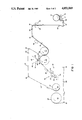
- FIG. 1 is a diagrammatic side view
- FIG. 2 is a diagrammatic top plan view of the preferred embodiment of apparatus for the practice of the invention.
- a supply roll 10 of the base tissue BT and a supply roll 12 of the overlay tissue OT are mounted on separate unwind stands (not shown) of conventional form having the usual unwind tension control brake, hand-adjustable. This brake is usually set to its approximate minimum.
- the base tissue is drawn from the supply roll 10 over intermediate idler rollers IR to a moistening unit, generally designated 14, by rotation of the backup roller 16 of the unit in the clockwise direction in the drawing as indicated by the arrow in FIG. 1.
- the moistening unit shown is a commercially available unit purchased from Dahlgren Manufacturing Company of Dallas, Tex.
- the backup roller 16 is rotated at a surface speed slightly slower than that of the heated roller 25 to which the base tissue passes after it is moistened by the unit 14, the roller 25 being rotated at the slightly higher surface speed of the laminate in the process.
- the light tension thus applied to the base tissue is beneficial in keeping it open and flat as it is transferring to heated roller 25.
- the nip between rollers 16 and 22 of the moistening unit is adjusted to slightly less clearance than the thickness of the base tissue, so that roller 22 just brushes the surface of the base tissue passing through the nip. Desirably, the adjustment permits the base tissue to be pulled through the nip by hand without turning the rollers 22 and 16, although the tissue is in sliding contact with both rollers. Referring to FIG.
- backup roll 16 is driven from the main drive shaft 24 by connection to speed change gearing 26 and intermediate gearing 28 connected to a manually operated clutch 30 on the shaft 32 of the roller 16.
- Transfer roller 22 is driven by a variable speed drive motor 34 connected to the roller shaft 36.
- the transfer roller functions to transfer to the exposed surface of the base tissue BT on the roller 16 at the nip a metered film of liquid applied to the transfer roller by the metering roller 18.
- the metering roller 18 is driven by a variable speed drive and motor unit 33 connected to its shaft 35. The amount of liquid transferred by the transfer roller 22 to the tissue is controlled by varying the speed of the transfer roller through connection of motor 34 to a moisture meter, as later described.
- the base tissue is drawn from roller 16 onto the surface of heated roller 25 by the rotation of that roller clockwise as indicated in FIG. 1 and as it approaches its uppermost position centered over its axis, where the exposed moistened surface of the base tissue BT is showered with dry absorbent particles by an applicator unit designated generally 40.
- This unit preferably, as shown, has a trough shaped feed hopper 42 mounted to extend across the path of the base tissue and containing a supply of the absorbent particles AP from which a shower S of the particles extending across the base tissue is produced as now described.
- Hopper 42 has an open bottom in which is mounted a full bristled rotary brush 44.
- a shroud and screen member 46 (FIG. 1) of substantially semi-circular cross-section is demountably attached to the bottom of hopper 42 and surrounds the bottom half of brush 44 with close clearance. The screen is located in the central 60° of member 46, the remainder of the member being a closed wall shroud.
- the opposite ends of shaft 48 of brush 44 are mounted in bearings in blocks 50 (FIG. 2) which are vertically movable in slideways on the opposite ends of hopper 42.
- Each block 50 has a mechanical jack mechanism (not shown) connected to it for independent vertical adjustment of the ends of shaft 48. The range of adjustment need not be large since normally only small fractions of an inch changes are made.
- Brush 44 is rotated by a motor and variable speed gearing unit 52 (FIG. 2) which may be mounted for vertical movement with blocks 50 or the motor may be fixedly mounted, with sliding parts provided in the gearing to accommodate the movement of the blocks.
- Brush 44 is rotated counterclockwise in FIG. 1 to convey the particles AP from the supply thereof in hopper 42, to which the upper half of the brush is continually exposed, to and through the screen of member 46 to form the shower S.
- the ends of shaft 44 are adjusted vertically to provide vertical alignment of the brush axis with the screen axis and to provide the desired amount of clearance (if any), between brush and screen. With these adjustments made to suit a particular type and amount of absorbent particles to be applied, control of the shower S to keep the applied particle layer within close limits of the target value is accomplished by varying the speed of rotation of the brush, as hereinafter described.
- the screen of member 46 desirably has as much open area as practical, with apertures of a size close to, but sufficient to clear, the largest size particles of the particular absorptive particles being used.
- a preferred superabsorbent particulate material a sodium acrylate polymer available under the trade designation "Water-Lock" J500 from Grain Processing Corporation of Muscatine, Ia.
- a preferred screen has a 15 ⁇ 15, 225 holes per square inch construction, with a hole diameter of 0.045 (1.14 mm) and an open area of 37%.
- the length of the screen in the direction of tissue travel is preferably about two inches, for an angular width of less than 50°, when applying 5 grams or less of the absorbent particles per square foot of the base tissue.
- the heated roller 25 which is heated by a circulating electrically heated oil system (not shown), is rotated at a surface speed equal to the processing speed of the laminate by a speed reducer unit 60 (FIG. 2) connected to a variable speed change unit 62 which in turn is connected to the drive shaft 64 of the roller 25.
- Main drive shaft 24 is driven by connection to a main motor 56.
- the overlay tissue OT is withdrawn by rotation of heated roller 25 from supply roll 12, over idler rollers IR and bowed spreader rollers SR, being laid over the particle layer on tissue BT immediately after the layer has been formed thereon. From this point, rotation of the roller 25 carries the assembled laminate to the nip of roller 25 and a slightly smaller diameter pressure roller 70 (as shown, 24 inches and 20 inches, respectively). Pressure roller 70 is rotated by roller 25 (through the intermediate laminate) in the same surface direction, as indicated by the arrows on these respective rollers. In accordance with previous description herein, pressure roller 70 has a steel core with a smooth elastomeric-covering of +90 Shore A Durometer hardness. Currently, the hardness of this rubber surface is 100 Shore A Durometer.
- Roll 70 is pivotally mounted 0435 for movement toward and away from roller 25 for initial threading purposes, and is hydraulically loaded (by conventional hydraulic pressure equipment not shown) to force it toward roller 25 to provide uniform pressure at the nip between the rollers of 350 pounds per square inch and upwards as far as desired, which includes a presently utilized pressure of about 450 pounds per square inch.
- the laminate After bonding at the pressure nip, the laminate is driven by the pressure nip and directed by idler rollers IR and bowed spreader rollers SR to be taken up by rewinding into a finished product roll 72.
- Roll 72 is mounted on a rewind stand of which only rollers 74 and 76 of the same diameter are shown.
- a core is placed on the rollers 74, 76 with its axis centered between them. These rollers are rotated in unison in the same direction as indicated by the arrows, which in turn rotates the core, winding the product around it. As the winding proceeds and the wound roll 72 thickens, the core rises correspondingly vertically in guideways provided in the stand.
- Roller 74 is driven (FIG. 2) from main motor 56 through speed change gearing 78, intermediate gearing 80 and a clutch 82 connecting to the shaft 84 of roller 74.
- Roller 74 drives roller 76 at the same speed through intermediate connections (not shown).
- speed change mechanism 78 is adjusted to rotate roller 74 at a surface speed equal to that of heated roller 25 so that the laminated product is at 0 to slight tension as it is drawn into the nip between the roller 74 and the wound roll 72. It should be noted that since rollers 16, 25 and 74 are driven from the main motor 56, increases or decreases in the speed of this motor will not change the pre-set speed ratios between these rollers, although changing the actual speeds of each of them.
- a moisture meter 86 is mounted to scan the laminate as it travels away from the nip of rollers 25 and 70.
- the particular meter used is of the infra-red type and was purchased from Moisture Systems, Inc. of Hopkinton, Mass. Meters for the same purpose of the same or other type are available from various suppliers and may be used.
- Meter 86 is electrically connected to the variable speed motor 34 which drives transfer roller 22 of the moistening unit, as indicated by the dashed line 88 in FIG. 2.
- the meter is set to have a first electrical output if the moisture reading exceeds the target value by a predetermined amount, and a second electrical output if the reading is a predetermined amount less than the target value. These two outputs are translated at motor 34 into opposite changes in the speed of rotation of transfer roller 22.
- Motor 34 is initially adjusted to provide an estimated proper surface speed for roller 22, this normally being about 100 feet per minute or more above the surface speed of the base tissue in the opposite direction.
- An electrical signal from meter 86 indicating too much moisture causes the speed of rotation of roller 22 to be reduced, reducing the amount of liquid applied to the base tissue, while a signal indicating too little moisture has the opposite effects. In this way the applied moisture is readily kept within ⁇ 10% of the target amount.
- the moisture meter 86 Since the moisture meter 86 is in position only to scan the product after it leaves the pressure nip, its readings do not precisely reflect the amount of moisture added. Instead, its readings give moisture applied less moisture loss up to the point of scanning. This is desirable, since if there is moisture loss above or below a normal minor amount, this too should be corrected by adding more or less moisture, respectively.
- the readings of the meter in its present location are considered sufficiently representative of the amount of applied moisture to make it unnecessary to provide a second meter scanning the base tissue as it passes from the moistener unit to the heated roller 25. The nul range of the meter 86 is thus adjusted to the target moisture content of the finished product rather than directly to applied moisture.
- Beta-Gage what is generally known as a "Beta-Gage", though other devices which are similarly effective may be used.
- the particular Beta-Gage used was purchased from Indev Corporation of East Buffalo, R.I.
- the source unit 90 emits energy rays from a source material such as promethium through the laminate to the detector unit 92, which reports detection to a computer 94 (FIG. 2) to which it has electrical connections indicated by dashed line 96 in FIG. 2.
- the computer correlates transmission and reception to provide weight readings such as in grams per unit area.
- Computer 94 can be programmed to provide electric output signals, transmitted by connected wiring indicated by dashed line 98 in FIG. 2, to actuate the speed change gearing of motor and gearing unit 52, altering the speed of rotation of the rotary brush 44 of the absorbent particle applicator 40, which is normally rotated at a speed between 2 and 4 r.p.m.
- a signal indicating too much weight slows the rotation of the brush to decrease the amount of absorptive particles in the shower S while a signal indicating too little weight has the opposite effects.
- the absorptive particle applicator is the only significant potential source of variation in product weight.
- Beta-Gage control applicator unit 40 along with the moisture meter control of the moistening unit 14, we have been consistently able to maintain finished product weight in grams per square foot within ⁇ 1/2 gram of target weight at all speeds utilized.
- the absorbent powder applicator unit is stopped by stopping brush motor 52, almost simultaneously with but slightly before, moving the backup roller 16 of the moistening unit 14 away from its transfer roller 22 to stop the moistening, then main motor 56 is shut down.
- the objective here is to prevent moistened base tissue without a layer of absorptive particles reaching the overlay tissue before the main motor is shut off, since this could wet the overlay tissue sufficiently to cause it to break if, as may often be the case, the overlay tissue has substantially zero wet strength.
- the pressure roller 70 is backed off the heated roller 25, opening the pressure nip, and the Beta-Gage is taken off-line.
- the pressure roller In re-starting the process, the pressure roller is returned to pressure nip position, the main motor 56 is started and gradually brought up to final operating speed, and the Beta-Gage is put on-line. Almost simultaneously, backup roller 16 is brought back to moistening position and brush motor 52 is turned on, but this time with moistening restored slightly before powder feeding.
Abstract
Description
Claims (7)
Priority Applications (1)
| Application Number | Priority Date | Filing Date | Title |
|---|---|---|---|
| US06/622,640 US4851069A (en) | 1984-06-20 | 1984-06-20 | Process for making tissue-absorbent particle laminates |
Applications Claiming Priority (1)
| Application Number | Priority Date | Filing Date | Title |
|---|---|---|---|
| US06/622,640 US4851069A (en) | 1984-06-20 | 1984-06-20 | Process for making tissue-absorbent particle laminates |
Publications (1)
| Publication Number | Publication Date |
|---|---|
| US4851069A true US4851069A (en) | 1989-07-25 |
Family
ID=24494947
Family Applications (1)
| Application Number | Title | Priority Date | Filing Date |
|---|---|---|---|
| US06/622,640 Expired - Fee Related US4851069A (en) | 1984-06-20 | 1984-06-20 | Process for making tissue-absorbent particle laminates |
Country Status (1)
| Country | Link |
|---|---|
| US (1) | US4851069A (en) |
Cited By (55)
| Publication number | Priority date | Publication date | Assignee | Title |
|---|---|---|---|---|
| US5160331A (en) * | 1991-07-12 | 1992-11-03 | Progeny Products, Inc. | Absorbent insert |
| US5175046A (en) * | 1991-03-04 | 1992-12-29 | Chicopee | Superabsorbent laminate structure |
| WO1994007547A1 (en) * | 1992-10-02 | 1994-04-14 | The Procter & Gamble Company | Method and apparatus for making cohesive sheets from particulate absorbent polymeric compositions |
| US5324561A (en) * | 1992-10-02 | 1994-06-28 | The Procter & Gamble Company | Porous, absorbent macrostructures of bonded absorbent particles surface crosslinked with cationic amino-epichlorohydrin adducts |
| US5328759A (en) * | 1991-11-01 | 1994-07-12 | Kimberly-Clark Corporation | Process for making a hydraulically needled superabsorbent composite material and article thereof |
| EP0656807A1 (en) * | 1992-08-28 | 1995-06-14 | Cer-Wat, Inc. | Filtration medium including substrate-supported porous membrane and method for the manufacture thereof |
| US5562646A (en) * | 1994-03-29 | 1996-10-08 | The Proctor & Gamble Company | Absorbent members for body fluids having good wet integrity and relatively high concentrations of hydrogel-forming absorbent polymer having high porosity |
| EP0745432A1 (en) * | 1995-06-01 | 1996-12-04 | The Procter & Gamble Company | Continuous adhesive printing onto discontinuous series of disposable absorbent article |
| US5607414A (en) * | 1993-10-21 | 1997-03-04 | The Procter & Gamble Company | Catamenial absorbent structures having thermally bonded layers for improved handling of menstrual fluids, and their use in catamenial pads having improved fit and comfort |
| US5628845A (en) * | 1995-09-28 | 1997-05-13 | Thermal Products, Inc. | Process for forming hydratable, flexible refrigement media |
| US5651862A (en) * | 1991-08-13 | 1997-07-29 | Kimberly-Clark Worldwide, Inc. | Wet-formed absorbent composite |
| US5863288A (en) * | 1995-09-29 | 1999-01-26 | Paragon Trade Brands, Inc. | Overlapped-style absorbent core structure comprising multiple storage and acquisition cells |
| WO1999019412A1 (en) * | 1997-10-10 | 1999-04-22 | Process Resources Corporation | Techniques for labeling of plastic, glass or metal containers or surfaces with polymeric labels |
| US5919178A (en) * | 1994-05-04 | 1999-07-06 | Sca Molnlycke Ab | Method for producing an absorbent structure which includes a layer of superabsorbent material |
| US5941862A (en) * | 1996-01-11 | 1999-08-24 | The Procter & Gamble | Absorbent structure having zones surrounded by a continuous region of hydrogel forming absorbent polymer |
| KR20000056964A (en) * | 1999-02-04 | 2000-09-15 | 윤광렬 | Tissue containing natural essential oil for post-treatmint of urination |
| US6214274B1 (en) | 1999-05-14 | 2001-04-10 | Kimberly-Clark Worldwide, Inc. | Process for compressing a web which contains superabsorbent material |
| US6290800B1 (en) * | 1999-12-02 | 2001-09-18 | Steven J. Antinori | Machine for and a method of manufacturing a laminate particularly adapted for bedding, padding, and upholstering |
| US6323388B1 (en) * | 1998-11-04 | 2001-11-27 | Kimberly-Clark Worldwide, Inc. | Absorbent article with an improved, wet-formed absorbent |
| US6340411B1 (en) | 1992-08-17 | 2002-01-22 | Weyerhaeuser Company | Fibrous product containing densifying agent |
| US6395395B1 (en) | 1992-08-17 | 2002-05-28 | Weyerhaeuser Company | Method and compositions for enhancing blood absorbence by superabsorbent materials |
| US6461553B1 (en) | 1992-08-17 | 2002-10-08 | Weyerhaeuser | Method of binding binder treated particles to fibers |
| US6572735B1 (en) | 1999-08-23 | 2003-06-03 | Kimberly-Clark Worldwide, Inc. | Wet-formed composite defining latent voids and macro-cavities |
| US6635134B1 (en) * | 1996-04-05 | 2003-10-21 | Eastern Pulp & Paper Corp. | Method of producing a spray bonded multi-ply tissue product |
| US20030220623A1 (en) * | 2000-09-21 | 2003-11-27 | The Procter & Gamble Company | Sbsorptive product having removable absorbers |
| US20040039361A1 (en) * | 1997-03-27 | 2004-02-26 | The Procter & Gamble Company | Disposable absorbent articles having multiple absorbent core components including replaceable components |
| US6706945B1 (en) | 1998-11-04 | 2004-03-16 | Kimberly-Clark Worldwide, Inc. | Absorbent article with improved, wet-formed absorbent |
| US20040058605A1 (en) * | 2002-09-19 | 2004-03-25 | Hansen Michael R. | Polysaccharide treated cellulose fibers |
| US20040137215A1 (en) * | 2001-05-04 | 2004-07-15 | Korma, S.P.A. | Method and device for production of a number of laminates |
| US20040203306A1 (en) * | 2002-11-13 | 2004-10-14 | Donaldson Company, Inc. | Wipe material with nanofiber layer on a flexible substrate |
| US20050000669A1 (en) * | 2003-03-14 | 2005-01-06 | Hugh West | Saccharide treated cellulose pulp sheets |
| US20050133180A1 (en) * | 2003-12-19 | 2005-06-23 | Hugh West | Densification agent and oil treated cellulose fibers |
| US20050178518A1 (en) * | 2004-02-13 | 2005-08-18 | Hugh West | Sodium sulfate treated pulp |
| US6932800B2 (en) | 1997-03-27 | 2005-08-23 | The Procter & Gamble Company | Absorbent articles comprising a material having a high vertical wicking capacity |
| US6979386B1 (en) | 1999-08-23 | 2005-12-27 | Kimberly-Clark Worldwide, Inc. | Tissue products having increased absorbency |
| US20060206087A1 (en) * | 1997-03-27 | 2006-09-14 | Lavon Gary D | Disposable absorbent articles having multiple absorbent core components including replaceable components |
| US20060217679A1 (en) * | 1998-09-28 | 2006-09-28 | Hanly Kevin B | Intravenous drug access system |
| US20060278335A1 (en) * | 2003-07-31 | 2006-12-14 | Livedo Corporation | Method and device for producing sheet-like body and method for producing disposable absorbent article using the sheet-like body |
| US7291137B2 (en) | 1997-03-27 | 2007-11-06 | The Procter & Gamble Company | Disposable absorbent articles having multiple absorbent core components including replaceable components |
| US20080103471A1 (en) * | 2006-10-26 | 2008-05-01 | The Procter & Gamble Company | Method for using a disposable absorbent article as a swim pant |
| US20080110775A1 (en) * | 2006-11-13 | 2008-05-15 | Theodora Beck | Absorbent articles with replaceable core components having stiffness characteristics and method for evaluating such characteristics |
| US20080114320A1 (en) * | 2006-11-13 | 2008-05-15 | Theodora Beck | Absorbent articles having fluid partitioning characteristics and method for evaluating such characteristics |
| US20090177174A1 (en) * | 2005-05-13 | 2009-07-09 | Asahi Kasei Chemicals | Absorbent composite material and method for manufacturing the same |
| US7601145B2 (en) | 1997-03-27 | 2009-10-13 | The Procter & Gamble Company | Disposable absorbent articles having multiple absorbent core components including replaceable components |
| US7727211B2 (en) | 2001-07-23 | 2010-06-01 | The Procter & Gamble Company | Absorbent article having a replaceable absorbent core component having an insertion pocket |
| US7766887B2 (en) | 2006-11-13 | 2010-08-03 | The Procter & Gamble Company | Method for making reusable disposable article |
| US20100212848A1 (en) * | 2002-05-10 | 2010-08-26 | Klaus Hilbig | Micro fiber textured paper tissue and method of making it |
| US7824387B2 (en) | 2006-10-26 | 2010-11-02 | The Procter & Gamble Company | Method for using a disposable absorbent article as training pant |
| US20110162989A1 (en) * | 2010-01-06 | 2011-07-07 | Ducker Paul M | Ultra thin laminate with particulates in dense packages |
| US20110166540A1 (en) * | 2010-01-06 | 2011-07-07 | Ching-Yun Morris Yang | Ultra-thin absorbent article |
| US20140144586A1 (en) * | 2011-07-08 | 2014-05-29 | Livedo Corporation | Particle supplying apparatus and sheet article manufacturing apparatus |
| US20140144587A1 (en) * | 2011-07-08 | 2014-05-29 | Livedo Corporation | Particle supplying apparatus and sheet article manufacturing apparatus |
| CN104842628A (en) * | 2015-05-13 | 2015-08-19 | 周和平 | Production device and production process of composite tissues |
| CN106471665A (en) * | 2014-07-02 | 2017-03-01 | 丰田自动车株式会社 | The method manufacturing lithium ion secondary battery electrode plate |
| US20200282716A1 (en) * | 2015-10-02 | 2020-09-10 | Assa Abloy Ab | Card substrate laminating device |
Citations (9)
| Publication number | Priority date | Publication date | Assignee | Title |
|---|---|---|---|---|
| US2988641A (en) * | 1957-01-28 | 1961-06-13 | Dunlop Rubber Co | Production of sheet materials |
| US3070095A (en) * | 1954-06-24 | 1962-12-25 | Torr David | Disposable multi-ply product |
| US3073736A (en) * | 1954-10-30 | 1963-01-15 | Frau Dr Wilma Wendt Geb Oellri | Method of bonding plastic sheets |
| US3098780A (en) * | 1958-08-04 | 1963-07-23 | Anaconda Aluminum Co | Curl resistant foil to paper lamination and method of making same |
| US3256138A (en) * | 1965-02-08 | 1966-06-14 | John A Manning Paper Co Inc | Application of resin particles to a wet fibrous ply in forming a multi-ply water-laid web |
| US4055180A (en) * | 1976-04-23 | 1977-10-25 | Colgate-Palmolive Company | Absorbent article with retained hydrocolloid material |
| US4260443A (en) * | 1978-10-20 | 1981-04-07 | Grain Processing Corporation | Laminated absorbent process |
| US4296234A (en) * | 1973-12-19 | 1981-10-20 | Lever Brothers Company | Absorbent materials |
| EP0080382A2 (en) * | 1981-11-24 | 1983-06-01 | Kimberly-Clark Limited | Microfibre web product |
-
1984
- 1984-06-20 US US06/622,640 patent/US4851069A/en not_active Expired - Fee Related
Patent Citations (9)
| Publication number | Priority date | Publication date | Assignee | Title |
|---|---|---|---|---|
| US3070095A (en) * | 1954-06-24 | 1962-12-25 | Torr David | Disposable multi-ply product |
| US3073736A (en) * | 1954-10-30 | 1963-01-15 | Frau Dr Wilma Wendt Geb Oellri | Method of bonding plastic sheets |
| US2988641A (en) * | 1957-01-28 | 1961-06-13 | Dunlop Rubber Co | Production of sheet materials |
| US3098780A (en) * | 1958-08-04 | 1963-07-23 | Anaconda Aluminum Co | Curl resistant foil to paper lamination and method of making same |
| US3256138A (en) * | 1965-02-08 | 1966-06-14 | John A Manning Paper Co Inc | Application of resin particles to a wet fibrous ply in forming a multi-ply water-laid web |
| US4296234A (en) * | 1973-12-19 | 1981-10-20 | Lever Brothers Company | Absorbent materials |
| US4055180A (en) * | 1976-04-23 | 1977-10-25 | Colgate-Palmolive Company | Absorbent article with retained hydrocolloid material |
| US4260443A (en) * | 1978-10-20 | 1981-04-07 | Grain Processing Corporation | Laminated absorbent process |
| EP0080382A2 (en) * | 1981-11-24 | 1983-06-01 | Kimberly-Clark Limited | Microfibre web product |
Non-Patent Citations (3)
| Title |
|---|
| Process of making Absorbent Laminates Practiced Commercially by (Assignee, Bird Machine Company, Inc.) of South Walpole, Mass., prior to Jun. 20, 1983. * |
| Reprint of article from "Index 78 Programme, Session 3: Hygiene Absorbent Products" of Paper 4 -Super-Absorbent Polymers for use with Body Exudates, by Schlauch et al., published prior to Jun. 20, 1984. |
| Reprint of article from Index 78 Programme, Session 3: Hygiene Absorbent Products of Paper 4 Super Absorbent Polymers for use with Body Exudates, by Schlauch et al., published prior to Jun. 20, 1984. * |
Cited By (106)
| Publication number | Priority date | Publication date | Assignee | Title |
|---|---|---|---|---|
| US5175046A (en) * | 1991-03-04 | 1992-12-29 | Chicopee | Superabsorbent laminate structure |
| US5160331A (en) * | 1991-07-12 | 1992-11-03 | Progeny Products, Inc. | Absorbent insert |
| US5651862A (en) * | 1991-08-13 | 1997-07-29 | Kimberly-Clark Worldwide, Inc. | Wet-formed absorbent composite |
| US5328759A (en) * | 1991-11-01 | 1994-07-12 | Kimberly-Clark Corporation | Process for making a hydraulically needled superabsorbent composite material and article thereof |
| US6340411B1 (en) | 1992-08-17 | 2002-01-22 | Weyerhaeuser Company | Fibrous product containing densifying agent |
| US6521087B2 (en) | 1992-08-17 | 2003-02-18 | Weyerhaeuser Company | Method for forming a diaper |
| US6627249B2 (en) | 1992-08-17 | 2003-09-30 | Weyerhaeuser Company | Method of enhancing blood absorbence by superabsorbent material |
| US6596103B1 (en) | 1992-08-17 | 2003-07-22 | Weyerhaeuser Company | Method of binding binder treated particles to fibers |
| US6521339B1 (en) | 1992-08-17 | 2003-02-18 | Weyerhaeuser Company | Diol treated particles combined with fibers |
| US6461553B1 (en) | 1992-08-17 | 2002-10-08 | Weyerhaeuser | Method of binding binder treated particles to fibers |
| US6425979B1 (en) | 1992-08-17 | 2002-07-30 | Weyerhaeuser Company | Method for making superabsorbent containing diapers |
| US20030201051A1 (en) * | 1992-08-17 | 2003-10-30 | Weyerhaeuser Company | Particle binding to fibers field of the invention |
| US6395395B1 (en) | 1992-08-17 | 2002-05-28 | Weyerhaeuser Company | Method and compositions for enhancing blood absorbence by superabsorbent materials |
| EP0656807A1 (en) * | 1992-08-28 | 1995-06-14 | Cer-Wat, Inc. | Filtration medium including substrate-supported porous membrane and method for the manufacture thereof |
| EP0656807A4 (en) * | 1992-08-28 | 1995-11-29 | Cer Wat Inc | Filtration medium including substrate-supported porous membrane and method for the manufacture thereof. |
| US5324561A (en) * | 1992-10-02 | 1994-06-28 | The Procter & Gamble Company | Porous, absorbent macrostructures of bonded absorbent particles surface crosslinked with cationic amino-epichlorohydrin adducts |
| WO1994007547A1 (en) * | 1992-10-02 | 1994-04-14 | The Procter & Gamble Company | Method and apparatus for making cohesive sheets from particulate absorbent polymeric compositions |
| US5451353A (en) * | 1992-10-02 | 1995-09-19 | Rezai; Ebrahim | Method of making porous, absorbent macrostructures of bonded absorbent particles surface crosslinked with cationic amino-epichlorohydrin adducts |
| SG83643A1 (en) * | 1992-10-02 | 2001-10-16 | Procter & Gamble | Method and apparatus for making cohesive sheets from particulate absorbent polymeric compositions |
| US5607414A (en) * | 1993-10-21 | 1997-03-04 | The Procter & Gamble Company | Catamenial absorbent structures having thermally bonded layers for improved handling of menstrual fluids, and their use in catamenial pads having improved fit and comfort |
| US5669894A (en) * | 1994-03-29 | 1997-09-23 | The Procter & Gamble Company | Absorbent members for body fluids having good wet integrity and relatively high concentrations of hydrogel-forming absorbent polymer |
| US5599335A (en) * | 1994-03-29 | 1997-02-04 | The Procter & Gamble Company | Absorbent members for body fluids having good wet integrity and relatively high concentrations of hydrogel-forming absorbent polymer |
| US5562646A (en) * | 1994-03-29 | 1996-10-08 | The Proctor & Gamble Company | Absorbent members for body fluids having good wet integrity and relatively high concentrations of hydrogel-forming absorbent polymer having high porosity |
| US5919178A (en) * | 1994-05-04 | 1999-07-06 | Sca Molnlycke Ab | Method for producing an absorbent structure which includes a layer of superabsorbent material |
| EP0745432A1 (en) * | 1995-06-01 | 1996-12-04 | The Procter & Gamble Company | Continuous adhesive printing onto discontinuous series of disposable absorbent article |
| US5628845A (en) * | 1995-09-28 | 1997-05-13 | Thermal Products, Inc. | Process for forming hydratable, flexible refrigement media |
| US5863288A (en) * | 1995-09-29 | 1999-01-26 | Paragon Trade Brands, Inc. | Overlapped-style absorbent core structure comprising multiple storage and acquisition cells |
| US5941862A (en) * | 1996-01-11 | 1999-08-24 | The Procter & Gamble | Absorbent structure having zones surrounded by a continuous region of hydrogel forming absorbent polymer |
| US6635134B1 (en) * | 1996-04-05 | 2003-10-21 | Eastern Pulp & Paper Corp. | Method of producing a spray bonded multi-ply tissue product |
| US20040060664A1 (en) * | 1996-04-05 | 2004-04-01 | Eastern Pulp And Paper Corporation, A Massachusetts Corporation | Apparatus for spray-bonding tissue |
| US20060206087A1 (en) * | 1997-03-27 | 2006-09-14 | Lavon Gary D | Disposable absorbent articles having multiple absorbent core components including replaceable components |
| US7381202B2 (en) | 1997-03-27 | 2008-06-03 | The Procter & Gamble Company | Disposable absorbent articles having multiple absorbent core components including replaceable components |
| US7291137B2 (en) | 1997-03-27 | 2007-11-06 | The Procter & Gamble Company | Disposable absorbent articles having multiple absorbent core components including replaceable components |
| US20080058754A1 (en) * | 1997-03-27 | 2008-03-06 | Lavon Gary D | Disposable absorbent articles having multiple absorbent core components including replaceable components |
| US20060217676A1 (en) * | 1997-03-27 | 2006-09-28 | Lavon Gary D | Disposable absorbent articles having multiple absorbent core components including replaceable components |
| US20060206086A1 (en) * | 1997-03-27 | 2006-09-14 | Lavon Gary D | Disposable absorbent articles having multiple absorbent core components including replaceable components |
| US20060206088A1 (en) * | 1997-03-27 | 2006-09-14 | Lavon Gary D | Disposable absorbent articles having multiple absorbent core components including replaceable components |
| US6989005B1 (en) | 1997-03-27 | 2006-01-24 | The Procter & Gamble Company | Absorbent articles having removable components |
| US20040039361A1 (en) * | 1997-03-27 | 2004-02-26 | The Procter & Gamble Company | Disposable absorbent articles having multiple absorbent core components including replaceable components |
| US6989006B2 (en) | 1997-03-27 | 2006-01-24 | The Procter And Gamble Company | Disposable absorbent articles having multiple absorbent core components including replaceable components |
| US7887524B2 (en) | 1997-03-27 | 2011-02-15 | The Procter & Gamble Company | Disposable absorbent articles having multiple absorbent core components including replaceable components |
| US20050256480A1 (en) * | 1997-03-27 | 2005-11-17 | La Von Gary D | Disposable absorbent articles having multiple absorbent core components including relpaceable components |
| US6932800B2 (en) | 1997-03-27 | 2005-08-23 | The Procter & Gamble Company | Absorbent articles comprising a material having a high vertical wicking capacity |
| US7727218B2 (en) | 1997-03-27 | 2010-06-01 | The Procter & Gamble Company | Disposable absorbent articles having multiple absorbent core components including replaceable components |
| US7670324B2 (en) | 1997-03-27 | 2010-03-02 | The Procter And Gamble Company | Disposable absorbent articles with replaceable absorbent core components having regions of permeability and impermeability on same surface |
| US7601145B2 (en) | 1997-03-27 | 2009-10-13 | The Procter & Gamble Company | Disposable absorbent articles having multiple absorbent core components including replaceable components |
| US8075542B2 (en) | 1997-03-27 | 2011-12-13 | The Procter & Gamble Company | Disposable absorbent articles having multiple absorbent core components including replaceable components |
| WO1999019412A1 (en) * | 1997-10-10 | 1999-04-22 | Process Resources Corporation | Techniques for labeling of plastic, glass or metal containers or surfaces with polymeric labels |
| US6306242B1 (en) * | 1997-10-10 | 2001-10-23 | Peter J. Dronzek | Techniques for labeling of plastic, glass or metal containers or surfaces with polymeric labels |
| US20060217679A1 (en) * | 1998-09-28 | 2006-09-28 | Hanly Kevin B | Intravenous drug access system |
| US6706945B1 (en) | 1998-11-04 | 2004-03-16 | Kimberly-Clark Worldwide, Inc. | Absorbent article with improved, wet-formed absorbent |
| US6323388B1 (en) * | 1998-11-04 | 2001-11-27 | Kimberly-Clark Worldwide, Inc. | Absorbent article with an improved, wet-formed absorbent |
| KR20000056964A (en) * | 1999-02-04 | 2000-09-15 | 윤광렬 | Tissue containing natural essential oil for post-treatmint of urination |
| US6214274B1 (en) | 1999-05-14 | 2001-04-10 | Kimberly-Clark Worldwide, Inc. | Process for compressing a web which contains superabsorbent material |
| US6572735B1 (en) | 1999-08-23 | 2003-06-03 | Kimberly-Clark Worldwide, Inc. | Wet-formed composite defining latent voids and macro-cavities |
| US6979386B1 (en) | 1999-08-23 | 2005-12-27 | Kimberly-Clark Worldwide, Inc. | Tissue products having increased absorbency |
| US20030149415A1 (en) * | 1999-08-23 | 2003-08-07 | Wallajapet Palani Raj Ramaswami | Wet-formed composite defining latent voids and macro-cavities |
| US6290800B1 (en) * | 1999-12-02 | 2001-09-18 | Steven J. Antinori | Machine for and a method of manufacturing a laminate particularly adapted for bedding, padding, and upholstering |
| US20030220623A1 (en) * | 2000-09-21 | 2003-11-27 | The Procter & Gamble Company | Sbsorptive product having removable absorbers |
| US7175613B2 (en) | 2000-09-21 | 2007-02-13 | The Procter & Gamble Company | Absorptive product having removable absorbers |
| US20070078420A1 (en) * | 2000-09-21 | 2007-04-05 | The Procter & Gamble Company | Absorptive product having removable absorbers |
| US7241358B2 (en) * | 2001-05-04 | 2007-07-10 | Korma, S.P.A. | Method and device for production of a number of laminates |
| US20040137215A1 (en) * | 2001-05-04 | 2004-07-15 | Korma, S.P.A. | Method and device for production of a number of laminates |
| US7494483B2 (en) | 2001-07-23 | 2009-02-24 | The Procter And Gamble Company | Disposable absorbent articles having multiple absorbent core components including replaceable components |
| US20060212016A1 (en) * | 2001-07-23 | 2006-09-21 | Lavon Gary D | Disposable absorbent articles having multiple absorbent core components including replaceable components |
| US7727211B2 (en) | 2001-07-23 | 2010-06-01 | The Procter & Gamble Company | Absorbent article having a replaceable absorbent core component having an insertion pocket |
| US20060253093A1 (en) * | 2001-07-23 | 2006-11-09 | The Procter & Gamble Company | Disposable absorbent articles having multiple absorbent core components including replaceable components |
| US20100212848A1 (en) * | 2002-05-10 | 2010-08-26 | Klaus Hilbig | Micro fiber textured paper tissue and method of making it |
| US20040058605A1 (en) * | 2002-09-19 | 2004-03-25 | Hansen Michael R. | Polysaccharide treated cellulose fibers |
| US20040203306A1 (en) * | 2002-11-13 | 2004-10-14 | Donaldson Company, Inc. | Wipe material with nanofiber layer on a flexible substrate |
| US8187241B2 (en) | 2002-12-03 | 2012-05-29 | The Procter & Gamble Company | Disposable absorbent articles having multiple absorbent core components including replaceable components |
| US8192415B2 (en) | 2002-12-03 | 2012-06-05 | The Procter & Gamble Company | Disposable absorbent articles having multiple absorbent core components including replaceable components |
| US20070083181A1 (en) * | 2002-12-03 | 2007-04-12 | Lavon Gary D | Disposable absorbent articles having multiple absorbent core components including replaceable components |
| US20050000669A1 (en) * | 2003-03-14 | 2005-01-06 | Hugh West | Saccharide treated cellulose pulp sheets |
| US8163124B2 (en) * | 2003-07-31 | 2012-04-24 | Livedo Corporation | Method and device for producing sheet-like body and method for producing disposable absorbent article using the sheet-like body |
| US20060278335A1 (en) * | 2003-07-31 | 2006-12-14 | Livedo Corporation | Method and device for producing sheet-like body and method for producing disposable absorbent article using the sheet-like body |
| US20090056867A1 (en) * | 2003-07-31 | 2009-03-05 | Livedo Corporation | Method and device for manufacturing sheet-shaped body and method for manufacturing disposable absorbent article using the sheet-shaped body |
| US20050133180A1 (en) * | 2003-12-19 | 2005-06-23 | Hugh West | Densification agent and oil treated cellulose fibers |
| US20050178518A1 (en) * | 2004-02-13 | 2005-08-18 | Hugh West | Sodium sulfate treated pulp |
| US8563127B2 (en) | 2005-05-13 | 2013-10-22 | Asahi Kasei Chemicals Corporation | Absorbent composite material and bodily fluid-absorbing article comprising water-absorbent resin particles having specific surface strength |
| US20090177174A1 (en) * | 2005-05-13 | 2009-07-09 | Asahi Kasei Chemicals | Absorbent composite material and method for manufacturing the same |
| US8778490B2 (en) | 2005-05-13 | 2014-07-15 | Asahi Kasei Chemicals Corporation | Absorbent composite material comprising water-absorbent resin particles having specific surface strength, and method for manufacturing the same |
| US8906176B2 (en) | 2005-05-13 | 2014-12-09 | Asahi Kasei Chemicals Corporation | Absorbent composite material and method for manufacturing the same |
| EP1880842B2 (en) † | 2005-05-13 | 2016-10-19 | Asahi Kasei Chemicals Corporation | Absorbent composite material and method for manufacturing the same |
| WO2008050310A1 (en) | 2006-10-26 | 2008-05-02 | The Procter & Gamble Company | Method for using a disposable absorbent article as a swim pant |
| US7824386B2 (en) | 2006-10-26 | 2010-11-02 | The Procter & Gamble Company | Method for using a disposable absorbent article as a swim pant |
| US20080103471A1 (en) * | 2006-10-26 | 2008-05-01 | The Procter & Gamble Company | Method for using a disposable absorbent article as a swim pant |
| US7824387B2 (en) | 2006-10-26 | 2010-11-02 | The Procter & Gamble Company | Method for using a disposable absorbent article as training pant |
| US20080110775A1 (en) * | 2006-11-13 | 2008-05-15 | Theodora Beck | Absorbent articles with replaceable core components having stiffness characteristics and method for evaluating such characteristics |
| US20100258242A1 (en) * | 2006-11-13 | 2010-10-14 | Burns Jr John Glasgow | Method for Making Reusable Disposable Article |
| US7766887B2 (en) | 2006-11-13 | 2010-08-03 | The Procter & Gamble Company | Method for making reusable disposable article |
| US20080114320A1 (en) * | 2006-11-13 | 2008-05-15 | Theodora Beck | Absorbent articles having fluid partitioning characteristics and method for evaluating such characteristics |
| US20110166540A1 (en) * | 2010-01-06 | 2011-07-07 | Ching-Yun Morris Yang | Ultra-thin absorbent article |
| US11432969B2 (en) | 2010-01-06 | 2022-09-06 | Eam Corporation | Ultra thin laminate with particulates in dense packages |
| US20110162989A1 (en) * | 2010-01-06 | 2011-07-07 | Ducker Paul M | Ultra thin laminate with particulates in dense packages |
| US9549858B2 (en) | 2010-01-06 | 2017-01-24 | Ching-Yun Morris Yang | Ultra-thin absorbent article |
| US20140144586A1 (en) * | 2011-07-08 | 2014-05-29 | Livedo Corporation | Particle supplying apparatus and sheet article manufacturing apparatus |
| US20140144587A1 (en) * | 2011-07-08 | 2014-05-29 | Livedo Corporation | Particle supplying apparatus and sheet article manufacturing apparatus |
| US9283119B2 (en) * | 2011-07-08 | 2016-03-15 | Livedo Corporation | Particle supplying apparatus and sheet article manufacturing apparatus |
| US9365023B2 (en) * | 2011-07-08 | 2016-06-14 | Livedo Corporation | Particle supplying apparatus and sheet article manufacturing apparatus |
| CN106471665A (en) * | 2014-07-02 | 2017-03-01 | 丰田自动车株式会社 | The method manufacturing lithium ion secondary battery electrode plate |
| US20170133659A1 (en) * | 2014-07-02 | 2017-05-11 | Toyota Jidosha Kabushiki Kaisha | Method of manufacturing lithium-ion secondary battery electrode sheet |
| US10468664B2 (en) * | 2014-07-02 | 2019-11-05 | Toyota Jidosha Kabushiki Kaisha | Method of manufacturing lithium-ion secondary battery electrode sheet |
| CN104842628A (en) * | 2015-05-13 | 2015-08-19 | 周和平 | Production device and production process of composite tissues |
| US20200282716A1 (en) * | 2015-10-02 | 2020-09-10 | Assa Abloy Ab | Card substrate laminating device |
| US11511530B2 (en) * | 2015-10-02 | 2022-11-29 | Assa Abloy Ab | Card substrate laminating device |
Similar Documents
| Publication | Publication Date | Title |
|---|---|---|
| US4851069A (en) | Process for making tissue-absorbent particle laminates | |
| KR930006464B1 (en) | Process for wrapping a rotating bale of a backed mineral fiber strip with a protective strip that is applied during winding of the bale for packaging | |
| US7595086B2 (en) | Method for producing corrugated cardboard | |
| US3556832A (en) | Method and apparatus for applying barrier coating substances to sheet materials | |
| US3764438A (en) | Method and apparatus for manufacturing laminated tube structure | |
| EP1375126A1 (en) | Method for producing corrugated cardboard | |
| US5221350A (en) | Gumming device for a strip of paper | |
| US20090188612A1 (en) | Machine for Bonding Films Made of Different Materials in Several Layers, and the Corresponding Method | |
| EP0388042B1 (en) | Pivoting guide for web conveying apparatus | |
| EP0324892B2 (en) | Plastic film bonding machine with adhesive spreading devices | |
| US3116194A (en) | Movable extruder | |
| US6004253A (en) | Medical adhesive bandage manufacturing | |
| CA1215311A (en) | Method and apparatus for bonding sheet material | |
| US3617422A (en) | Tape applicator | |
| US4192712A (en) | Combined breaker size press coater | |
| CA1132858A (en) | Web coater | |
| US3547735A (en) | Machine for butt joining the longitudinal edges of thin,flat workpieces | |
| US1965719A (en) | Method and machine for making laminated paper | |
| AU565282B2 (en) | Methods and apparatus for making sandwich webs | |
| US2788840A (en) | Method for producing pipe covering and the like | |
| US3330717A (en) | Laminating apparatus | |
| CN216965110U (en) | Automatic glue spreader | |
| US3340128A (en) | Apparatus for producing nonwoven fibrous product | |
| CN212979393U (en) | Automatic glue spreader of cardboard | |
| CN213472494U (en) | Polyester film delivery glue scraping device for cable composite non-woven fabric material production line |
Legal Events
| Date | Code | Title | Description |
|---|---|---|---|
| AS | Assignment |
Owner name: BIRD MACHINE COMPANY, INC., SOUTH WALPOLE, MA A MA Free format text: ASSIGNMENT OF ASSIGNORS INTEREST.;ASSIGNORS:PACKARD, THOMAS D.;GOODCHILD, WILLIAM C.;REEL/FRAME:004277/0115 Effective date: 19840619 |
|
| AS | Assignment |
Owner name: MICREX CORPORATION, WALPOLE, MA A CORP. OF MA Free format text: ASSIGNMENT OF ASSIGNORS INTEREST.;ASSIGNOR:BIRD MACHINE COMPANY, INC.;REEL/FRAME:004896/0983 Effective date: 19880106 Owner name: MICREX CORPORATION, A CORP. OF MA,MASSACHUSETTS Free format text: ASSIGNMENT OF ASSIGNORS INTEREST;ASSIGNOR:BIRD MACHINE COMPANY, INC.;REEL/FRAME:004896/0983 Effective date: 19880106 |
|
| AS | Assignment |
Owner name: MICREX CORPORATION, WALPOLE, MA A CORP. OF MA Free format text: ASSIGNMENT OF ASSIGNORS INTEREST.;ASSIGNOR:BIRD MACHINE COMPANY, INC.,;REEL/FRAME:004947/0894 Effective date: 19880106 |
|
| CC | Certificate of correction | ||
| FEPP | Fee payment procedure |
Free format text: PAT HOLDER CLAIMS SMALL ENTITY STATUS - SMALL BUSINESS (ORIGINAL EVENT CODE: SM02); ENTITY STATUS OF PATENT OWNER: SMALL ENTITY Free format text: PAYOR NUMBER ASSIGNED (ORIGINAL EVENT CODE: ASPN); ENTITY STATUS OF PATENT OWNER: SMALL ENTITY |
|
| FPAY | Fee payment |
Year of fee payment: 4 |
|
| AS | Assignment |
Owner name: WALTON, RICHARD C., MASSACHUSETTS Free format text: ASSIGNMENT OF ASSIGNORS INTEREST;ASSIGNORS:WALTON, RICHARD C. (EXECUTOR);WALTON, RICHARD R. (DECEASED);REEL/FRAME:007656/0535 Effective date: 19950925 |
|
| FPAY | Fee payment |
Year of fee payment: 8 |
|
| AS | Assignment |
Owner name: LANTOR, INC., MASSACHUSETTS Free format text: ASSIGNMENT OF ASSIGNORS INTEREST;ASSIGNOR:WALTON, RICHARD C.;REEL/FRAME:010263/0721 Effective date: 19990921 |
|
| FEPP | Fee payment procedure |
Free format text: PAYER NUMBER DE-ASSIGNED (ORIGINAL EVENT CODE: RMPN); ENTITY STATUS OF PATENT OWNER: SMALL ENTITY Free format text: PAYOR NUMBER ASSIGNED (ORIGINAL EVENT CODE: ASPN); ENTITY STATUS OF PATENT OWNER: SMALL ENTITY |
|
| REMI | Maintenance fee reminder mailed | ||
| LAPS | Lapse for failure to pay maintenance fees | ||
| FP | Lapsed due to failure to pay maintenance fee |
Effective date: 20010725 |
|
| STCH | Information on status: patent discontinuation |
Free format text: PATENT EXPIRED DUE TO NONPAYMENT OF MAINTENANCE FEES UNDER 37 CFR 1.362 |