US4875469A - Continuous passive motion devices and methods - Google Patents
Continuous passive motion devices and methods Download PDFInfo
- Publication number
- US4875469A US4875469A US07/206,269 US20626988A US4875469A US 4875469 A US4875469 A US 4875469A US 20626988 A US20626988 A US 20626988A US 4875469 A US4875469 A US 4875469A
- Authority
- US
- United States
- Prior art keywords
- finger
- belt
- carriage
- drive
- set forth
- Prior art date
- Legal status (The legal status is an assumption and is not a legal conclusion. Google has not performed a legal analysis and makes no representation as to the accuracy of the status listed.)
- Expired - Fee Related
Links
- 230000033001 locomotion Effects 0.000 title claims abstract description 54
- 238000000034 method Methods 0.000 title claims description 6
- 230000008878 coupling Effects 0.000 claims description 14
- 238000010168 coupling process Methods 0.000 claims description 14
- 238000005859 coupling reaction Methods 0.000 claims description 14
- 210000000707 wrist Anatomy 0.000 claims description 14
- 210000003414 extremity Anatomy 0.000 claims description 8
- 239000006260 foam Substances 0.000 claims description 5
- 230000007246 mechanism Effects 0.000 claims description 3
- 239000000853 adhesive Substances 0.000 claims description 2
- 230000001070 adhesive effect Effects 0.000 claims description 2
- 125000004122 cyclic group Chemical group 0.000 claims 1
- 230000005284 excitation Effects 0.000 claims 1
- 230000005057 finger movement Effects 0.000 claims 1
- 210000003811 finger Anatomy 0.000 description 76
- 210000003813 thumb Anatomy 0.000 description 8
- 210000000245 forearm Anatomy 0.000 description 7
- 241000282472 Canis lupus familiaris Species 0.000 description 4
- 230000003287 optical effect Effects 0.000 description 4
- 230000001225 therapeutic effect Effects 0.000 description 3
- 230000000712 assembly Effects 0.000 description 2
- 238000000429 assembly Methods 0.000 description 2
- 230000008901 benefit Effects 0.000 description 2
- 230000000903 blocking effect Effects 0.000 description 2
- 230000006835 compression Effects 0.000 description 2
- 238000007906 compression Methods 0.000 description 2
- 230000000694 effects Effects 0.000 description 2
- 208000011092 Hand injury Diseases 0.000 description 1
- 206010028289 Muscle atrophy Diseases 0.000 description 1
- 208000027418 Wounds and injury Diseases 0.000 description 1
- 230000009471 action Effects 0.000 description 1
- 230000002457 bidirectional effect Effects 0.000 description 1
- 238000009835 boiling Methods 0.000 description 1
- 230000006378 damage Effects 0.000 description 1
- 210000004905 finger nail Anatomy 0.000 description 1
- 230000035876 healing Effects 0.000 description 1
- 230000002401 inhibitory effect Effects 0.000 description 1
- 208000014674 injury Diseases 0.000 description 1
- 210000003127 knee Anatomy 0.000 description 1
- 238000011068 loading method Methods 0.000 description 1
- 239000000463 material Substances 0.000 description 1
- 230000004048 modification Effects 0.000 description 1
- 238000012986 modification Methods 0.000 description 1
- 230000002093 peripheral effect Effects 0.000 description 1
- 238000007493 shaping process Methods 0.000 description 1
- 239000007787 solid Substances 0.000 description 1
- 230000000472 traumatic effect Effects 0.000 description 1
- XLYOFNOQVPJJNP-UHFFFAOYSA-N water Substances O XLYOFNOQVPJJNP-UHFFFAOYSA-N 0.000 description 1
Images


Classifications
-
- A—HUMAN NECESSITIES
- A61—MEDICAL OR VETERINARY SCIENCE; HYGIENE
- A61H—PHYSICAL THERAPY APPARATUS, e.g. DEVICES FOR LOCATING OR STIMULATING REFLEX POINTS IN THE BODY; ARTIFICIAL RESPIRATION; MASSAGE; BATHING DEVICES FOR SPECIAL THERAPEUTIC OR HYGIENIC PURPOSES OR SPECIFIC PARTS OF THE BODY
- A61H1/00—Apparatus for passive exercising; Vibrating apparatus ; Chiropractic devices, e.g. body impacting devices, external devices for briefly extending or aligning unbroken bones
- A61H1/02—Stretching or bending or torsioning apparatus for exercising
- A61H1/0274—Stretching or bending or torsioning apparatus for exercising for the upper limbs
- A61H1/0285—Hand
- A61H1/0288—Fingers
Definitions
- This invention relates to devices for imparting continuous passive motion to a limb or digit, and more particularly to portable units for exercising joints of the hand, fingers and wrist.
- the devices depicted therein are not indicative of the state of the art, however, since units with additional features have been sold for some time by Kinetec of France, and by Toronto Medical Inc. of Yellow Springs, Ohio. Even such units, however, provide only a limited ability to supply motion effects and controls as dictated by a therapist for a given individual.
- the French system is a relatively cumbersome unit which must be operated from a power main.
- the Toronto Medical Inc. product is a portable battery operated device for exercising the fingers.
- a light weight battery operated CPM is very useful because of the frequency of occurrence of hand injuries, provided that a variety of manipulative CPM functions can be performed.
- the unit should also be adaptable for imparting continuous passive motion to the thumb, and alternatively to the wrist.
- the unit should also permit a therapist to exercise only certain fingers and to introduce digit blocking or to exercise only particular fingers or joints.
- a portable CPM unit should not only be light in weight but efficient in operation so that it can operate for a long interval on battery power. Moreover, not only the range of travel but the speed of reciprocation should be adjustable. Various useful features, such as counting the number of cycles, automatic resetting and manual or automatic operation, should also be provided.
- An improved battery powered CPM device for hand, thumb and wrist applications incorporates a double belt drive system in which the belts are drivable from a motor and engageable by an intercoupling clutch.
- a carriage engaged to a primary drive belt is the base for one or a number of telescoping finger actuators which are internally spring loaded and pivotable through limited angles.
- Flag elements coupled to the belts are separately settable to define opposite limit positions with the belt drive disengaged, by taking the fingers or wrist through the desired range of motion. Thereafter, simply engaging the clutch starts the run operation.
- the belts and carriage are reciprocated at a selected and variable rate between the defined limit positions under solid state electronic control which counts the cycles and reverses the motor, introducing dwell times as desired.
- the unit may be automatically reset whenever the range of travel is changed.
- the base unit is coupled to a unit holder which is mountable on the forearm and enables the carriage to be coupled to actuators for any or all of the four fingers or the thumb or via an attachment to the wrist.
- the fingers may be exercised through different ranges including from fully extended to flexed and from flexed to clenched, by reorientation of the elements.
- the telescoping finger actuators are mounted on the carriage so as to be pivotable through small diverging angles to conform to the shape of the hand and fingers of the individual patient.
- the finger actuators include base tubes receiving rod extensions which may be locked in selected axial positions. Terminal flexible spring wires on the actuators are engaged to finger attachments at their outer end, and are seated within the rod extensions between a pair of compression springs at their opposite end. Thus, whether moving the fingers toward the extended or clenched position, the actuators, which are readily adjusted to individual finger lengths, introduce a spring force against the fingers.
- the device is mounted on an arm cuff that fits on the forearm and provides a base that accommodates different arm sizes.
- the device may be mounted directly on the arm cuff, or on a separate unit holder, which may incorporate a pivotable base surface for providing a controlled degree of tilt relative to the wrist angle in the lateral and vertical planes.
- the anterior of the arm cuff includes a tang on which a thermoplastically deformable palm support or digit blocking device can be engaged after shaping to the particular needs of the patient's hand.
- Finger attachments for coupling to the finger actuators advantageously comprise arcuate elements partially encompassing a finger tip and including a protruding lever arm engageable to the flexible actuator wires. Forces exerted on the finger tips by the actuators act against the sides of the fingers in shear. Securement to the fingers can be within the attachment and elastic coupled to close the arcuate elements.
- the attachments may be placed on the fingers in inverted position so that motion can be introduced to provide a clenched fist.
- the same unit can be used to provide continuous passive motion of one or more digits, including the thumb. With an adaptor it may also be used to exercise the wrist. It can be increased in size and drive capability to move other limbs, such as the elbow and knee, with appropriate known types of attachments.
- FIG. 1 is a perspective view of a continuous passive motion device in accordance with the invention
- FIG. 2 is a different perspective view, partially broken away, of a portion of the arrangement of FIG. 1;
- FIG. 3 is a second fragmentary view of the arrangement of FIG. 1, showing internal details thereof;
- FIG. 4 is a fragmentary perspective view, partially broken away, of a portion of the arrangement of FIGS. 1-3, showing details of the clutch and drive subsystem;
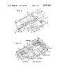
- FIG. 5 is a side sectional view of finger actuators used in the arrangement of FIGS. 1-4;
- FIG. 6 is an exploded view of unit holder and digit blocker devices for use in the arrangement of FIGS. 1-4;
- FIG. 7 is a perspective view of a device in accordance with the invention mounted for moving the fingers from flexed to fully clenched position;
- FIG. 8 is a perspective view of a device in accordance with the invention with an attachment for continuous passive motion of the wrist;
- FIG. 9 is a fragmentary perspective view of a finger attachment device used in the arrangement of FIGS. 1-4.
- FIG. 10 is a side sectional view of a portion of the housing unit holder and arm cuff of FIG. 6.
- devices in accordance with the invention comprise a housing 10 which contains or supports the principal drive elements and in addition a battery, motor and controller.
- the housing 10 has a hinged cover 11 and is mounted on a support 12 which is affixed to the forearm, here positioning the housing 10 so that it is adjacent the palm of the hand, to enable the fingers to be flexed from a fully extended to partially flexed position in this example.
- a foam pad 13 (FIG. 1) is typically disposed on the wrist under the support 12.
- the cover 11 is mounted on the housing 10 by pivot hinges 14 along one edge and encompasses some of the exterior drive elements and controls, such as an on-off control switch 16, and a control lever 18.
- the lever 18 is shiftable manually between setup and run positions, and is moved automatically to the run position by the cover when the cover 11 is closed.
- the housing 10 supports a linearly movable carriage 20 which is coupled to a drive mechanism inside the body through a linear slot 22 that extends in the posterior/anterior direction.
- a number of finger actuator assemblies 24 are individually mounted on pivot pins 25 on the posterior end of the carriage 20, extending outwardly toward the finger tips.
- the finger actuator assemblies 24 each include a base tube 26 having a tang 28 at its free end that is incurved to grip a slidable inserted hollow extension rod 30 at a selected telescoping position. These positions are defined by a number of longitudinally spaced short peripheral slots 32 periodically spaced along the extension rod 30 and receiving the tips of the tangs 28.
- a first spring 34 is disposed in the extension rod 30 at the posterior end, as seen in FIG.
- a strong but resilient wire element 36 having a terminating projection 37 at its end inside the extension rod 30 and an end loop 38 at its anterior end provides the means for coupling to an individual finger attachment. Between the terminating extension 37 and the anterior end, within the extension rod 30, is disposed a second spring 40 between end caps 41 having central apertures through which the wire 36 is inserted and moves.
- the carriage 20 moves along the exposed surface of the housing 10, between a side rail 44 and a side wall of the cover 11, which restrict outward divergence of the finger actuators 24.
- the bases 45 of the actuators 24 include holes fitting about the pivot pins 25, and are sized to limit the maximum angle of divergence between adjacent actuators 24.
- the end loops 38 on the wires 36 are each coupled to a finger attachment device 46 at a protruding lever arm 48, by passing through a transverse opening 49 on the lever arm 48.
- the finger attachment device 46 comprises a curved base 50 which conforms to the pad of a finger tip and is bounded on each side by a hinge 51 joining to an adjacent side panel 52.
- Each side panel includes a protruding post 53, so that the device can be curved snugly about the finger by an elastic band 58 coupling the posts 53.
- Such posts may be provided alternatively on the base 50 or the arm 48.
- a foam insert 60 having adhesive surfaces on both sides is disposed between the finger attachment device 46 and the finger to increase adhesion and resistance to shear forces. For some applications a foam insert will not be needed.
- the entire finger attachment device 46 apart from the foam insert 60 and the elastic band 58 is conveniently molded as a single integral piece.
- the energy source and drive mechanism, as well as the internal sensing and control system, are disposed within the body, as may be seen by reference to FIGS. 3 and 4.
- a battery 62 is coupled via a controller 63 to a D.C. drive motor 64.
- the controller 63 also receives sensor signals via a P.C. board 65 and contains circuitry for controlling reciprocating motion at a selectable velocity between choosable limits, for enabling manual and automatic operation, and for providing an indication of the number of cycles of operation, as well as automatic reset.
- Such functions can be controlled individually by separate conventional circuits but the cost and flexibility of integrated circuit chips enable these features, together with many more if desired, to be provided at reasonable cost.
- the motor 64 is mounted in the housing 10, being principally supported in the motor mount 66 at its shaft 68 end, and the shaft being conventonally seated between bearing plates in the body.
- the shaft 68 extends in a direction perpendicular to the direction of reciprocation of the carriage 20.
- a first drive belt 70 engages a first drive pulley 72 on the shaft 68, the first drive pulley being rotatable on the shaft 68, but having a clutch face with circumferentially spaced slots 73 on the side opposite the motor 64.
- the motor shaft need not be integral but may include one or more colinear sections or couplings.
- a clutch element 74 about the shaft 68 includes a set of protruding dogs 76 configured to mate within the drive pulley slots 73, the clutch elements 74 being axially movable toward the motor 64 by the control lever 18 as described hereafter.
- the clutch element 74 is engaged with the dogs 76 in the drive pulley slots 73, the clutch element, which is coupled to the shaft 68, rotates the first drive belt 70 with the shaft 68.
- a second drive belt 78 parallel to the drive belt 70 but spaced apart along the shaft 68 on the opposite side of the clutch element 74, is directly coupled to the motor shaft 68 by a second drive pulley 80, which is axially movable along the shaft on a splined section (not shown in detail).
- a leaf spring 82 mounted on the side of the device body 10 urges the second drive pulley 80 in the direction toward the motor 64, but engagement of the clutch device is controlled by the control lever 18.
- the upper end of the lever 18 is accessible through a slot from the top of the body 10, while the lower end is mounted on a pivot 84 in the wall of the body 10.
- a side of the control lever 18 engages the adjacent side of the first drive pulley 72 next to the slots 73, and in the "setup" position of the control lever 18 shifts the first drive pulley out of engagement with the dogs 76 on the clutch element 74.
- the control lever 18 permits engagement of the dogs 76 into the drive pulley slots 73.
- a bracket 85 extending from a mid-region of the control lever 18 carries a wire arm 86 which, in the "run” position, engages a spring actuator 87 having a tab 88 which passes into the optical path of a position sensor 90 of the type having a small miniaturized light source on one side and a light sensor on the other. Signals from this sensor 90 are passed to the P.C. board 65 and controller 63 for use in the system.
- the first and second drive belts 70, 78 are turned about driven pulleys 92, 93 mounted on a common shaft 94 coupled to the body 10.
- a bracket 98 coupled to the first drive belt by a U-shaped element 99 is coupled to the carriage 20 through the linear slot 22 (not seen in FIG. 3), to control carriage motion and position.
- a flag 100 on the bracket 98 extends in the anterior direction, along a path adjacent to the first drive belt 70, and at a predetermined limit position near the driven pulleys 72, 73, passes into the optical path of a second position sensor 102.
- a fixture 104 mounted on the second drive belt 78 carries a flag 105 directed in the posterior direction which intercepts the optical path of a third position sensor 108 at a limit position.
- the control switch 16 has automatic, manual and off positions accessible to the user.
- a digital display 112 visible to the user provides the count generated by the controller 63.
- Rotatable control buttons 114, 115, designated P and S can be used to adjust the dwell time before reversal of direction and the rate of travel of the carriage 20, respectively.
- a pair of depressible buttons 116, 117 labeled "Extend” and “Flex” respectively, can operate the motor in the given directions.
- the support 12 may comprise an arm cuff 120 having an anterior tang 122 and a shaped configuration for fitting smoothly about the base of the wrist, with the tang 122 extending onto the palm.
- the arm cuff 120 At the posterior end of the arm cuff 120 are provided slots 124, which establish flexible side wings 126 so that the arm cuff may be fitted onto forearms of substantially varying sizes.
- Straps 128 with conventional means for joinder, such as snaps or "Velcro" are placed about the arm cuff 120 and the forearm.
- the housing 10 may be inserted directly with a snap attachment into the arm cuff 120, or optionally may be mounted, as seen in FIGS.
- a hinged base support or unit holder 130 having an upper surface 131 which can be raised to different angular positions for best fitting to the particular hand or function.
- a digit blocker 132 having a shaped slot 134 may be fitted onto the tang 122 on the arm cuff 120, so as to restrict movement of individual joints in any fashion that a therapist may desire.
- the anterior portion of the digit blocker comprises a shaped body 136 of thermoformable plastic. Plastic materials are available which are rigid at ambient temperature but which become plastic at moderate temperatures (e.g. hot water below boiling) and which may therefore be shaped, cut and fit by a therapist to fit the palm and particular needs of an individual patient, and then allowed to cool to rigidity.
- the operation of the system of FIGS. 1-6 proceeds by first attaching the finger attachments 46 to the fingers as desired.
- the finger attachments 46 are seated with the lever arms 48 protruding from the finger tip pads, and the wires 36 are then engaged to the lever arms by inserting the end loops 38, which permit bidirectional motion.
- the base tubes 26 can conveniently be kept on the pivot pins 25, and the extension rods 30 can be temporarily extracted for this attachment.
- the fingers are then fully extended, and the extension rods 30 are extended or contracted to given positions, within the base tubes 26, by rotating the rods 30 through a small angle so that the slots 32 are not in alignment with the tangs 28 on the base tube 26.
- each finger can be precisely adjusted in length, and the tension at the fully extended position can also be controlled, by the length of the extension.
- the springs 34, 40 inside the extension rod 30 have approximately equal compliance and thus will compress slightly under light force, as determined by a therapist or user.
- the hinged cover 11 With the support 12 strapped onto the wrist, and the housing 10 of the device attached, the hinged cover 11 can be opened to permit these adjustments to be made.
- the control lever 18 is shifted to the "setup" position, which frees the first drive belt 70 from the motor shaft 68, allowing the carriage 20 to be moved, along with the fingers, posteriorly to a selected flex position.
- the controller 63 automatically drives the motor 64 to bring the second drive belt 78 toward the rearward position, until the flag 105 on the fixture 104 for the second drive belt 78 intercepts the third position sensor 108. This therefore provides a reference for the flexed position of the drive system.
- the carriage 20 is moved, along with the fingers, to the desired flex position, only the first drive belt 70 moves with it, starting from the fully extended position in which the flag 100 on the bracket is at the second position sensor 102.
- This sequence is very simply established for the therapist or user, and if the stroke adjustment are not as desired, the sequence maybe quickly repeated to achieve final settings.
- the system may then be shifted from the "setup” mode to the "run” mode simply by shifting the control lever 18 and closing the cover 11. It is advantageous to position the control lever 18 as shown, so that this shift in control lever position automatically occurs when the cover 11 is closed.
- the unit thus operates continuously, at the selected advance and return velocities, in reciprocating fashion, with the limiting positions of the carriage 20 being sensed by the second and third optical sensors 102, 108, respectively.
- the cycles of movement are counted and displayed, and if the system is reset, the count, in this example, is started over again.
- the physical movement of the finger tips is precisely controlled, because the divergence of the finger actuators 24 corresponds to actual finger alignment, and because the arrangement of the finger attachments 46 aids in proper vectorial distribution of forces.
- the forces which draw the fingers inwardly and extend them reciprocally act on the lever arms 48, but are absorbed in shear at the side panels 52, rather than the fleshy part at the pad of the finger.
- the finger attachments 46 are reversed or inverted, with the protruding lever arms extending outwardly from the fingernails. Now, as seen in FIG. 7, the fingers can be drawn from a partially flexed position down into contact with the palm of the hand.
- the same carriage 20 and base tube 26 arrangement are employed, but the extension rod 30' is terminated by a bracket 130 supporting a transverse bar 132 which fits through the holes in the finger attachments 46. This enables movement to form a complete fist.
- the finger actuator structure plays an important part in the distribution of forces.
- the wire elements 36 compress the first springs 34 when extending, and compress the second springs 40 when flexing the fingers.
- the actuators can be adjusted to provide a given tension force on them, by placement of the tension rods 30 relative to the base tubes 26. This provides an important therapeutic advantage, because it is often useful to hold the fingers under tension at a limit position for a period of time prior to continuing with the reciprocating motion. This dwell time can be adjusted using the controller 36 and the selector buttons 114, 115.
- the same unit, with the single finger actuator, can be used for controlling the motion of the thumb through different ranges as shown in dotted lines in FIG. 1.
- the attachment 46 to the end of the thumb can be placed as desired, and the wire element 36 extending from the finger actuator 24 is typically substantially bent, but still functions to provide the control thumb motion that is desired.
- a wrist adaptor 140 fitting about the back or palm of the hand includes an upwardly extending lever 142 to which the wire loop 38 is attached at one of a number of spaced apart holes 144.
- the body of the adaptor 140 includes slots 146 for receiving attachment straps 148 by which the unit can be affixed to the extensor surface of the patient's forearm.
- the nature and arc of the continuous passive motion can be selected by using different ones of the holes 144.
- the device can be mounted on either forearm so as to function with either hand. If a cast is in place the unit holder can be strapped directly onto it, without an intervening arm cuff.
Abstract
Description
Claims (23)
Priority Applications (1)
| Application Number | Priority Date | Filing Date | Title |
|---|---|---|---|
| US07/206,269 US4875469A (en) | 1988-06-13 | 1988-06-13 | Continuous passive motion devices and methods |
Applications Claiming Priority (1)
| Application Number | Priority Date | Filing Date | Title |
|---|---|---|---|
| US07/206,269 US4875469A (en) | 1988-06-13 | 1988-06-13 | Continuous passive motion devices and methods |
Publications (1)
| Publication Number | Publication Date |
|---|---|
| US4875469A true US4875469A (en) | 1989-10-24 |
Family
ID=22765659
Family Applications (1)
| Application Number | Title | Priority Date | Filing Date |
|---|---|---|---|
| US07/206,269 Expired - Fee Related US4875469A (en) | 1988-06-13 | 1988-06-13 | Continuous passive motion devices and methods |
Country Status (1)
| Country | Link |
|---|---|
| US (1) | US4875469A (en) |
Cited By (81)
| Publication number | Priority date | Publication date | Assignee | Title |
|---|---|---|---|---|
| US5117814A (en) * | 1990-03-16 | 1992-06-02 | Q-Motus, Inc. | Dynamic splint |
| EP0516876A1 (en) * | 1991-06-06 | 1992-12-09 | Patrick Timothy Donohue | Digital traction system |
| US5252102A (en) * | 1989-01-24 | 1993-10-12 | Electrobionics Corporation | Electronic range of motion apparatus, for orthosis, prosthesis, and CPM machine |
| US5261393A (en) * | 1992-09-17 | 1993-11-16 | Norman Weinzweig | Removable flexible finger covering with fingertip connector clip |
| US5267924A (en) * | 1993-01-07 | 1993-12-07 | Advanced Kinetics, Inc. | Apparatus and method for imparting continuous passive motion to the foot |
| US5303696A (en) * | 1992-03-09 | 1994-04-19 | Boice Steven D | Method and apparatus for imparting continuous passive motion to joints and related structure |
| US5348531A (en) * | 1992-12-11 | 1994-09-20 | Smith & Nephew Rolyan, Inc. | Wrap-on finger hooks |
| US5447490A (en) * | 1992-12-17 | 1995-09-05 | Smith & Nephew Rolyan, Inc. | Finger rehabilitation system |
| US5451191A (en) * | 1994-08-05 | 1995-09-19 | Beenken; Gregory M. | Finger rehabilitation/exercise device |
| US5458560A (en) * | 1993-09-03 | 1995-10-17 | Jace Systems, Inc. | Continuous passive motion device for a wrist |
| US5472407A (en) * | 1993-10-13 | 1995-12-05 | Schenck; Robert R. | Motorized dynamic traction device |
| US5514052A (en) * | 1994-02-24 | 1996-05-07 | Charles; Gene | Finger exerciser |
| US5538488A (en) * | 1995-06-08 | 1996-07-23 | Villepigue; James C. | Exercising glove |
| US5683351A (en) * | 1994-09-27 | 1997-11-04 | Jace Systems, Inc. | Continuous passive motion device for a hand |
| US5746704A (en) * | 1995-08-04 | 1998-05-05 | Schenck; Robert R. | Therapy apparatus having a passive motion device for flexing a body member |
| US5820577A (en) * | 1996-09-26 | 1998-10-13 | Taylor; Terrence M. | Finger exercise device |
| WO1999045864A1 (en) * | 1998-03-11 | 1999-09-16 | University College London | Joint motion device |
| US5954621A (en) * | 1993-07-09 | 1999-09-21 | Kinetecs, Inc. | Exercise apparatus and technique |
| US5980435A (en) * | 1993-07-09 | 1999-11-09 | Kinetecs, Inc. | Methods of therapy or controlled exercise using a jointed brace |
| US6447425B1 (en) * | 2000-06-14 | 2002-09-10 | Paracomp, Inc. | Range of motion device |
| US6450924B1 (en) * | 1999-10-08 | 2002-09-17 | Block Patents, Inc. | Finger exercise device |
| US6537075B1 (en) * | 2000-01-11 | 2003-03-25 | Francisco J. Valero-Cuevas | Device for developing and measuring grasping force and grasping dexterity |
| KR100391583B1 (en) * | 2001-03-31 | 2003-07-12 | 윤태병 | Intelligence development device by finger motions |
| US20030162634A1 (en) * | 2002-02-25 | 2003-08-28 | Farrell John F. | Dynamic resting hand splint |
| US20050101887A1 (en) * | 1998-09-01 | 2005-05-12 | Izex Technologies, Inc. | Orthoses for joint rehabilitation |
| EP1549263A1 (en) * | 2002-09-04 | 2005-07-06 | Northern Sydney Area Health Service | Movement facilitation device |
| US20050273027A1 (en) * | 2002-02-25 | 2005-12-08 | Saebo, Inc. | Dynamic hand splint |
| US6988998B1 (en) * | 2005-01-18 | 2006-01-24 | Horacio Santaana-Dela Rosa | Dynamic dorsal-blocking adjustable splint |
| US20060247102A1 (en) * | 2003-04-21 | 2006-11-02 | Scott Kupferman | Hand exercising device |
| US20060287160A1 (en) * | 2005-06-16 | 2006-12-21 | Geller Andrew S | Two-piece finger weight device II |
| US20070055191A1 (en) * | 2004-12-30 | 2007-03-08 | Saebo, Inc. | Dynamic splint assemblies |
| US20070060448A1 (en) * | 2005-09-15 | 2007-03-15 | Robert Silagy | Exercise device |
| US20070129653A1 (en) * | 2003-04-24 | 2007-06-07 | Thomas Sugar | Spring-over-muscle actuator |
| US20070173747A1 (en) * | 2006-01-24 | 2007-07-26 | Knotts Jesse A | Joint stimulator |
| US20080114271A1 (en) * | 2006-11-13 | 2008-05-15 | David Rubenstein | Method of neuromuscular calibration |
| US20090156361A1 (en) * | 2007-10-31 | 2009-06-18 | Frederic Ferri | Hand and finger-therapy device |
| US20090192420A1 (en) * | 2008-01-25 | 2009-07-30 | Armstrong Ned B | Reciprocating brace |
| US20090197741A1 (en) * | 2008-02-06 | 2009-08-06 | Gary Poillucci | Hand, Wrist and Arm Therapy and Exercising |
| US20100130895A1 (en) * | 2008-01-25 | 2010-05-27 | Armstrong Ned B | Reciprocating brace |
| CN101797204A (en) * | 2010-03-26 | 2010-08-11 | 中国人民解放军第三军医大学第一附属医院 | Rehabilitative manipulator for hand burns and scalds |
| US20100217168A1 (en) * | 2005-06-23 | 2010-08-26 | Marcus James King | Orthosis |
| US20100222722A1 (en) * | 2002-04-18 | 2010-09-02 | Leismer Jeffrey M | Musculoskeletal loading device |
| WO2010140984A1 (en) * | 2009-06-03 | 2010-12-09 | National University Of Singapore | Finger function rehabilitation device |
| CN101548926B (en) * | 2009-05-13 | 2011-01-05 | 郭淑梅 | Electric arm functional exerciser |
| US7892194B2 (en) | 2004-12-10 | 2011-02-22 | Saebo, Inc. | Dynamic hand splints |
| WO2011094841A1 (en) * | 2010-02-04 | 2011-08-11 | Vincent Chau | Passive exercise apparatus |
| ITMI20100466A1 (en) * | 2010-03-23 | 2011-09-24 | Idrogenet Srl | HAND REHABILITATION DEVICE |
| WO2011117901A1 (en) | 2010-03-23 | 2011-09-29 | Idrogenet S.R.L. | A hand rehabilitation device |
| WO2011119902A1 (en) * | 2010-03-25 | 2011-09-29 | Randall Fenkell | Continuous passive motion device |
| WO2011124917A1 (en) | 2010-04-06 | 2011-10-13 | I2R Medical Limited | Therapeutic hand exercise device |
| US20120059291A1 (en) * | 2010-09-03 | 2012-03-08 | Bes Rehab Ltd. | Apparatus for manipulating joints of a limb |
| KR101264560B1 (en) | 2011-12-19 | 2013-05-14 | 문창수 | Motion apparatus orthosis for upper extremity |
| US20130144195A1 (en) * | 2010-07-06 | 2013-06-06 | Aldo Cehic | Device for Passive Movement of the Fingers |
| US8491572B2 (en) | 2004-11-15 | 2013-07-23 | Izex Technologies, Inc. | Instrumented orthopedic and other medical implants |
| US8784475B2 (en) | 2004-11-15 | 2014-07-22 | Izex Technologies, Inc. | Instrumented implantable stents, vascular grafts and other medical devices |
| US8790258B2 (en) | 1999-06-23 | 2014-07-29 | Izex Technologies, Inc. | Remote psychological evaluation |
| WO2015047070A1 (en) * | 2013-09-24 | 2015-04-02 | Universidad Nacional Autónoma de México | Orthotic device for assisting with bending and extending movements of the fingers of a hand, for patients suffering from paralysis of the brachial plexus |
| DE102014004508A1 (en) * | 2014-03-27 | 2015-10-01 | Institut Für Technische Informatik Universität Zu Lübeck | Device for supporting gripping functions of a hand for training gripping functions |
| US20150374575A1 (en) * | 2014-06-30 | 2015-12-31 | Rehabilitation Institute Of Chicago | Actuated glove orthosis and related methods |
| US20160199246A1 (en) * | 2015-01-14 | 2016-07-14 | Yeung Ki Kim | Upper limb rehabilitation training apparatus |
| US9470474B1 (en) * | 2013-09-13 | 2016-10-18 | Steven K. Uhlmann | Device for cyclically operating a firearm trigger |
| CN106038018A (en) * | 2016-07-01 | 2016-10-26 | 南京富帆健康管理咨询服务有限公司 | Rehabilitation orthosis for rupture of finger flexor tendon |
| USD787515S1 (en) * | 2015-08-24 | 2017-05-23 | Flint Rehabilitation Devices, LLC | Hand-worn user interface device |
| US9757266B2 (en) | 2010-06-01 | 2017-09-12 | Saebo, Inc. | Orthotic device |
| US9764190B2 (en) | 2012-06-13 | 2017-09-19 | Saebo, Inc. | Dynamic hand splints |
| CN108096790A (en) * | 2018-01-31 | 2018-06-01 | 力迈德医疗(广州)有限公司 | Finger rehabilitation training robot |
| US20180168907A1 (en) * | 2016-12-20 | 2018-06-21 | Rehabotics Medical Technology Corporation | Wearable hand rehabilitation system |
| WO2019075567A1 (en) * | 2017-10-18 | 2019-04-25 | Johnson Vineet Benjamin K | System and method for providing indirect movement feedback during sensorimotor function rehabilitation and enhancement |
| US20190295435A1 (en) * | 2016-05-18 | 2019-09-26 | Daniele RAIMONDI | Apparatus for improving the technical ability related to the use of a musical instrument, in particular for training the fingers of a hand |
| USD865086S1 (en) | 2018-07-19 | 2019-10-29 | Gary Poillucci | Sleeve for exercise apparatus |
| USD881298S1 (en) | 2018-07-30 | 2020-04-14 | Gary Poillucci | Hand exercise apparatus |
| USD881296S1 (en) | 2018-07-19 | 2020-04-14 | Gary Poillucci | Exercise apparatus |
| USD881297S1 (en) | 2018-07-19 | 2020-04-14 | Gary Poillucci | Mobile exercise apparatus |
| US10643498B1 (en) * | 2016-11-30 | 2020-05-05 | Ralityworks, Inc. | Arthritis experiential training tool and method |
| US20200368095A1 (en) * | 2018-12-18 | 2020-11-26 | Bionik, Inc. | Apparatus and/or Method for Positioning a Hand for Rehabilitation |
| US20210059888A1 (en) * | 2018-05-16 | 2021-03-04 | Adjuvo Motion B.V. | Exoskeleton Glove |
| US11083233B2 (en) | 2017-10-20 | 2021-08-10 | Felix KING, III | Therapeutic glove for support and exercise of fingers and wrist |
| US11224553B2 (en) * | 2016-01-29 | 2022-01-18 | Fundación Tecnalia Research & Innovation | Hand rehabilitation device |
| US11534358B2 (en) | 2019-10-11 | 2022-12-27 | Neurolutions, Inc. | Orthosis systems and rehabilitation of impaired body parts |
| USD980990S1 (en) * | 2021-11-05 | 2023-03-14 | Shenzhen Kunshengze Electronic Commerce Co., Ltd. | Finger stretcher |
| WO2023141007A1 (en) * | 2022-01-19 | 2023-07-27 | Animo Bionics Corp. | Telekinetic bionic glove assembly |
Citations (9)
| Publication number | Priority date | Publication date | Assignee | Title |
|---|---|---|---|---|
| US3631542A (en) * | 1969-08-11 | 1972-01-04 | Univ Iowa State Res Found | Myoelectric brace |
| US3756222A (en) * | 1971-12-27 | 1973-09-04 | Univ Kansas State | Electrically driven hand exerciser |
| US3871646A (en) * | 1973-02-26 | 1975-03-18 | Robert W Slack | Exercise apparatus |
| US4538595A (en) * | 1984-02-21 | 1985-09-03 | Hajianpour Muhamad A | Passive exercising device |
| US4576148A (en) * | 1984-02-03 | 1986-03-18 | Sutter Biomedical, Inc. | Continuous passive motion hand device |
| US4644938A (en) * | 1985-01-22 | 1987-02-24 | Danninger Medical Technology | Hand exerciser |
| US4665900A (en) * | 1981-10-23 | 1987-05-19 | Toronto Medical Corp. | Device for imparting continuous passive motion to human joints |
| US4679548A (en) * | 1984-02-01 | 1987-07-14 | Compagnie Generale De Material Orthopedique | Re-education apparatus for the articulated segments of the hand |
| US4724827A (en) * | 1985-01-10 | 1988-02-16 | Schenck Robert R | Dynamic traction device |
-
1988
- 1988-06-13 US US07/206,269 patent/US4875469A/en not_active Expired - Fee Related
Patent Citations (9)
| Publication number | Priority date | Publication date | Assignee | Title |
|---|---|---|---|---|
| US3631542A (en) * | 1969-08-11 | 1972-01-04 | Univ Iowa State Res Found | Myoelectric brace |
| US3756222A (en) * | 1971-12-27 | 1973-09-04 | Univ Kansas State | Electrically driven hand exerciser |
| US3871646A (en) * | 1973-02-26 | 1975-03-18 | Robert W Slack | Exercise apparatus |
| US4665900A (en) * | 1981-10-23 | 1987-05-19 | Toronto Medical Corp. | Device for imparting continuous passive motion to human joints |
| US4679548A (en) * | 1984-02-01 | 1987-07-14 | Compagnie Generale De Material Orthopedique | Re-education apparatus for the articulated segments of the hand |
| US4576148A (en) * | 1984-02-03 | 1986-03-18 | Sutter Biomedical, Inc. | Continuous passive motion hand device |
| US4538595A (en) * | 1984-02-21 | 1985-09-03 | Hajianpour Muhamad A | Passive exercising device |
| US4724827A (en) * | 1985-01-10 | 1988-02-16 | Schenck Robert R | Dynamic traction device |
| US4644938A (en) * | 1985-01-22 | 1987-02-24 | Danninger Medical Technology | Hand exerciser |
Non-Patent Citations (2)
| Title |
|---|
| "Hand Orthosis Dynamic Bracing Using Gauged Spiral Springs" by Allieu and Rouzaud, 10-1986. |
| Hand Orthosis Dynamic Bracing Using Gauged Spiral Springs by Allieu and Rouzaud, 10 1986. * |
Cited By (120)
| Publication number | Priority date | Publication date | Assignee | Title |
|---|---|---|---|---|
| US5252102A (en) * | 1989-01-24 | 1993-10-12 | Electrobionics Corporation | Electronic range of motion apparatus, for orthosis, prosthesis, and CPM machine |
| US5117814A (en) * | 1990-03-16 | 1992-06-02 | Q-Motus, Inc. | Dynamic splint |
| EP0516876A1 (en) * | 1991-06-06 | 1992-12-09 | Patrick Timothy Donohue | Digital traction system |
| US5303696A (en) * | 1992-03-09 | 1994-04-19 | Boice Steven D | Method and apparatus for imparting continuous passive motion to joints and related structure |
| US5261393A (en) * | 1992-09-17 | 1993-11-16 | Norman Weinzweig | Removable flexible finger covering with fingertip connector clip |
| US5348531A (en) * | 1992-12-11 | 1994-09-20 | Smith & Nephew Rolyan, Inc. | Wrap-on finger hooks |
| US5447490A (en) * | 1992-12-17 | 1995-09-05 | Smith & Nephew Rolyan, Inc. | Finger rehabilitation system |
| US5267924A (en) * | 1993-01-07 | 1993-12-07 | Advanced Kinetics, Inc. | Apparatus and method for imparting continuous passive motion to the foot |
| US5954621A (en) * | 1993-07-09 | 1999-09-21 | Kinetecs, Inc. | Exercise apparatus and technique |
| US5980435A (en) * | 1993-07-09 | 1999-11-09 | Kinetecs, Inc. | Methods of therapy or controlled exercise using a jointed brace |
| US5620410A (en) * | 1993-09-03 | 1997-04-15 | Jace Systems, Inc. | Continuous passive motion device for a wrist |
| US5458560A (en) * | 1993-09-03 | 1995-10-17 | Jace Systems, Inc. | Continuous passive motion device for a wrist |
| US5472407A (en) * | 1993-10-13 | 1995-12-05 | Schenck; Robert R. | Motorized dynamic traction device |
| US5514052A (en) * | 1994-02-24 | 1996-05-07 | Charles; Gene | Finger exerciser |
| US5451191A (en) * | 1994-08-05 | 1995-09-19 | Beenken; Gregory M. | Finger rehabilitation/exercise device |
| US5683351A (en) * | 1994-09-27 | 1997-11-04 | Jace Systems, Inc. | Continuous passive motion device for a hand |
| US5538488A (en) * | 1995-06-08 | 1996-07-23 | Villepigue; James C. | Exercising glove |
| US5746704A (en) * | 1995-08-04 | 1998-05-05 | Schenck; Robert R. | Therapy apparatus having a passive motion device for flexing a body member |
| US5820577A (en) * | 1996-09-26 | 1998-10-13 | Taylor; Terrence M. | Finger exercise device |
| WO1999045864A1 (en) * | 1998-03-11 | 1999-09-16 | University College London | Joint motion device |
| US20050101887A1 (en) * | 1998-09-01 | 2005-05-12 | Izex Technologies, Inc. | Orthoses for joint rehabilitation |
| US8678979B2 (en) | 1998-09-01 | 2014-03-25 | Izex Technologies, Inc. | Remote monitoring of a patient |
| US9230057B2 (en) | 1998-09-01 | 2016-01-05 | Izex Technologies, Inc. | Remote monitoring of a patient |
| US8790258B2 (en) | 1999-06-23 | 2014-07-29 | Izex Technologies, Inc. | Remote psychological evaluation |
| US6450924B1 (en) * | 1999-10-08 | 2002-09-17 | Block Patents, Inc. | Finger exercise device |
| US6537075B1 (en) * | 2000-01-11 | 2003-03-25 | Francisco J. Valero-Cuevas | Device for developing and measuring grasping force and grasping dexterity |
| US6447425B1 (en) * | 2000-06-14 | 2002-09-10 | Paracomp, Inc. | Range of motion device |
| KR100391583B1 (en) * | 2001-03-31 | 2003-07-12 | 윤태병 | Intelligence development device by finger motions |
| US7001352B2 (en) * | 2002-02-25 | 2006-02-21 | Saebo, Inc. | Dynamic resting hand splint |
| US8328743B2 (en) | 2002-02-25 | 2012-12-11 | Saebo, Inc. | Dynamic hand splint |
| US20030162634A1 (en) * | 2002-02-25 | 2003-08-28 | Farrell John F. | Dynamic resting hand splint |
| US20090326428A1 (en) * | 2002-02-25 | 2009-12-31 | Saebo, Inc. | Dynamic hand splint |
| US7601130B2 (en) | 2002-02-25 | 2009-10-13 | Saebo, Inc. | Dynamic hand splint |
| US20050273027A1 (en) * | 2002-02-25 | 2005-12-08 | Saebo, Inc. | Dynamic hand splint |
| US8740826B2 (en) * | 2002-04-18 | 2014-06-03 | Jeffrey M. Leismer | Musculoskeletal loading device |
| US20100222722A1 (en) * | 2002-04-18 | 2010-09-02 | Leismer Jeffrey M | Musculoskeletal loading device |
| US20060094989A1 (en) * | 2002-09-04 | 2006-05-04 | Scott Timothy Roderick D | Movement facilitation device |
| EP1549263A1 (en) * | 2002-09-04 | 2005-07-06 | Northern Sydney Area Health Service | Movement facilitation device |
| EP1549263A4 (en) * | 2002-09-04 | 2007-04-25 | Northern Sydney And Central Co | Movement facilitation device |
| US7481782B2 (en) | 2002-09-04 | 2009-01-27 | Northern Sydney Area Health Service | Movement facilitation device |
| US20060247102A1 (en) * | 2003-04-21 | 2006-11-02 | Scott Kupferman | Hand exercising device |
| US20100311546A1 (en) * | 2003-04-21 | 2010-12-09 | Scott Kupferman | Hand exercising device |
| US7740561B2 (en) * | 2003-04-21 | 2010-06-22 | Scott Kupferman | Hand exercising device |
| US20070129653A1 (en) * | 2003-04-24 | 2007-06-07 | Thomas Sugar | Spring-over-muscle actuator |
| US8491572B2 (en) | 2004-11-15 | 2013-07-23 | Izex Technologies, Inc. | Instrumented orthopedic and other medical implants |
| US8740879B2 (en) | 2004-11-15 | 2014-06-03 | Izex Technologies, Inc. | Instrumented orthopedic and other medical implants |
| US8784475B2 (en) | 2004-11-15 | 2014-07-22 | Izex Technologies, Inc. | Instrumented implantable stents, vascular grafts and other medical devices |
| US20110144552A1 (en) * | 2004-12-10 | 2011-06-16 | John Fletcher Farrell | Dynamic hand splints |
| US8328744B2 (en) | 2004-12-10 | 2012-12-11 | Saebo, Inc. | Dynamic hand splints |
| US7892194B2 (en) | 2004-12-10 | 2011-02-22 | Saebo, Inc. | Dynamic hand splints |
| US7458947B2 (en) | 2004-12-30 | 2008-12-02 | Saebo, Inc. | Dynamic splint assemblies |
| EP1841686A4 (en) * | 2004-12-30 | 2010-08-18 | Saebo Inc | Dynamic splint assembly |
| EP1841686A2 (en) * | 2004-12-30 | 2007-10-10 | Saebo, Inc. | Dynamic splint assembly |
| US20070055191A1 (en) * | 2004-12-30 | 2007-03-08 | Saebo, Inc. | Dynamic splint assemblies |
| US6988998B1 (en) * | 2005-01-18 | 2006-01-24 | Horacio Santaana-Dela Rosa | Dynamic dorsal-blocking adjustable splint |
| US7662068B1 (en) * | 2005-06-16 | 2010-02-16 | Geller Andrew S | Two-piece finger weight device IV |
| US20060287160A1 (en) * | 2005-06-16 | 2006-12-21 | Geller Andrew S | Two-piece finger weight device II |
| US20100217168A1 (en) * | 2005-06-23 | 2010-08-26 | Marcus James King | Orthosis |
| US7381156B2 (en) | 2005-09-15 | 2008-06-03 | Robert Silagy | Exercise device |
| US20070060448A1 (en) * | 2005-09-15 | 2007-03-15 | Robert Silagy | Exercise device |
| US20070173747A1 (en) * | 2006-01-24 | 2007-07-26 | Knotts Jesse A | Joint stimulator |
| WO2008002617A2 (en) * | 2006-06-27 | 2008-01-03 | Clinically Fit, Inc. | Hand exercising device |
| WO2008002617A3 (en) * | 2006-06-27 | 2008-04-10 | Clinically Fit Inc | Hand exercising device |
| US20080114271A1 (en) * | 2006-11-13 | 2008-05-15 | David Rubenstein | Method of neuromuscular calibration |
| US20090156361A1 (en) * | 2007-10-31 | 2009-06-18 | Frederic Ferri | Hand and finger-therapy device |
| US8814812B2 (en) * | 2008-01-25 | 2014-08-26 | M.A.R.B. Rehab International, Inc. | Reciprocating brace |
| US20090192420A1 (en) * | 2008-01-25 | 2009-07-30 | Armstrong Ned B | Reciprocating brace |
| US8888724B2 (en) * | 2008-01-25 | 2014-11-18 | M.A.R.B. Rehab International, Llc | Reciprocating brace |
| US20100130895A1 (en) * | 2008-01-25 | 2010-05-27 | Armstrong Ned B | Reciprocating brace |
| US20090197741A1 (en) * | 2008-02-06 | 2009-08-06 | Gary Poillucci | Hand, Wrist and Arm Therapy and Exercising |
| CN101548926B (en) * | 2009-05-13 | 2011-01-05 | 郭淑梅 | Electric arm functional exerciser |
| WO2010140984A1 (en) * | 2009-06-03 | 2010-12-09 | National University Of Singapore | Finger function rehabilitation device |
| WO2011094841A1 (en) * | 2010-02-04 | 2011-08-11 | Vincent Chau | Passive exercise apparatus |
| WO2011117901A1 (en) | 2010-03-23 | 2011-09-29 | Idrogenet S.R.L. | A hand rehabilitation device |
| US9375382B2 (en) * | 2010-03-23 | 2016-06-28 | Idrogenet S.R.L. | Hand rehabilitation device |
| ITMI20100466A1 (en) * | 2010-03-23 | 2011-09-24 | Idrogenet Srl | HAND REHABILITATION DEVICE |
| CN102811690A (en) * | 2010-03-23 | 2012-12-05 | 伊德洛有限公司 | A hand rehabilitation device |
| US20130072829A1 (en) * | 2010-03-23 | 2013-03-21 | Davide Fausti | Hand rehabilitation device |
| CN102811690B (en) * | 2010-03-23 | 2016-11-09 | 伊德洛有限公司 | Hand rehabilitation device |
| WO2011119902A1 (en) * | 2010-03-25 | 2011-09-29 | Randall Fenkell | Continuous passive motion device |
| CN101797204A (en) * | 2010-03-26 | 2010-08-11 | 中国人民解放军第三军医大学第一附属医院 | Rehabilitative manipulator for hand burns and scalds |
| WO2011124917A1 (en) | 2010-04-06 | 2011-10-13 | I2R Medical Limited | Therapeutic hand exercise device |
| US9545356B2 (en) | 2010-04-06 | 2017-01-17 | I2R Medical Limited | Therapeutic hand exercise device |
| US9757266B2 (en) | 2010-06-01 | 2017-09-12 | Saebo, Inc. | Orthotic device |
| US9301898B2 (en) * | 2010-07-06 | 2016-04-05 | Aldo Cehic | Device for passive movement of the fingers |
| US20130144195A1 (en) * | 2010-07-06 | 2013-06-06 | Aldo Cehic | Device for Passive Movement of the Fingers |
| US8622939B2 (en) * | 2010-09-03 | 2014-01-07 | Bes Rehab Ltd. | Apparatus for manipulating joints of a limb |
| US20120059291A1 (en) * | 2010-09-03 | 2012-03-08 | Bes Rehab Ltd. | Apparatus for manipulating joints of a limb |
| KR101264560B1 (en) | 2011-12-19 | 2013-05-14 | 문창수 | Motion apparatus orthosis for upper extremity |
| US9764190B2 (en) | 2012-06-13 | 2017-09-19 | Saebo, Inc. | Dynamic hand splints |
| US9470474B1 (en) * | 2013-09-13 | 2016-10-18 | Steven K. Uhlmann | Device for cyclically operating a firearm trigger |
| WO2015047070A1 (en) * | 2013-09-24 | 2015-04-02 | Universidad Nacional Autónoma de México | Orthotic device for assisting with bending and extending movements of the fingers of a hand, for patients suffering from paralysis of the brachial plexus |
| DE102014004508A1 (en) * | 2014-03-27 | 2015-10-01 | Institut Für Technische Informatik Universität Zu Lübeck | Device for supporting gripping functions of a hand for training gripping functions |
| US10478370B2 (en) * | 2014-06-30 | 2019-11-19 | Rehabilitation Institute Of Chicago | Actuated glove orthosis and related methods |
| US20150374575A1 (en) * | 2014-06-30 | 2015-12-31 | Rehabilitation Institute Of Chicago | Actuated glove orthosis and related methods |
| US20160199246A1 (en) * | 2015-01-14 | 2016-07-14 | Yeung Ki Kim | Upper limb rehabilitation training apparatus |
| USD787515S1 (en) * | 2015-08-24 | 2017-05-23 | Flint Rehabilitation Devices, LLC | Hand-worn user interface device |
| US11224553B2 (en) * | 2016-01-29 | 2022-01-18 | Fundación Tecnalia Research & Innovation | Hand rehabilitation device |
| US20190295435A1 (en) * | 2016-05-18 | 2019-09-26 | Daniele RAIMONDI | Apparatus for improving the technical ability related to the use of a musical instrument, in particular for training the fingers of a hand |
| US10672291B2 (en) * | 2016-05-18 | 2020-06-02 | Daniele RAIMONDI | Apparatus for improving the technical ability related to the use of a musical instrument, in particular for training the fingers of a hand |
| CN106038018A (en) * | 2016-07-01 | 2016-10-26 | 南京富帆健康管理咨询服务有限公司 | Rehabilitation orthosis for rupture of finger flexor tendon |
| US10643498B1 (en) * | 2016-11-30 | 2020-05-05 | Ralityworks, Inc. | Arthritis experiential training tool and method |
| US20180168907A1 (en) * | 2016-12-20 | 2018-06-21 | Rehabotics Medical Technology Corporation | Wearable hand rehabilitation system |
| US10849815B2 (en) * | 2016-12-20 | 2020-12-01 | Rehabotics Medical Technology Corporation | Wearable hand rehabilitation system |
| US11596831B2 (en) * | 2017-10-18 | 2023-03-07 | Iregained Inc. | System and method for providing indirect movement feedback during sensorimotor function rehabilitation and enhancement |
| WO2019075567A1 (en) * | 2017-10-18 | 2019-04-25 | Johnson Vineet Benjamin K | System and method for providing indirect movement feedback during sensorimotor function rehabilitation and enhancement |
| US11083233B2 (en) | 2017-10-20 | 2021-08-10 | Felix KING, III | Therapeutic glove for support and exercise of fingers and wrist |
| CN108096790A (en) * | 2018-01-31 | 2018-06-01 | 力迈德医疗(广州)有限公司 | Finger rehabilitation training robot |
| CN108096790B (en) * | 2018-01-31 | 2023-10-20 | 力迈德医疗(广州)有限公司 | Finger rehabilitation training robot |
| US20210059888A1 (en) * | 2018-05-16 | 2021-03-04 | Adjuvo Motion B.V. | Exoskeleton Glove |
| USD881296S1 (en) | 2018-07-19 | 2020-04-14 | Gary Poillucci | Exercise apparatus |
| USD865086S1 (en) | 2018-07-19 | 2019-10-29 | Gary Poillucci | Sleeve for exercise apparatus |
| USD881297S1 (en) | 2018-07-19 | 2020-04-14 | Gary Poillucci | Mobile exercise apparatus |
| USD881298S1 (en) | 2018-07-30 | 2020-04-14 | Gary Poillucci | Hand exercise apparatus |
| US11744763B2 (en) * | 2018-12-18 | 2023-09-05 | Bionik, Inc. | Apparatus and/or method for positioning a hand for rehabilitation |
| US20200368095A1 (en) * | 2018-12-18 | 2020-11-26 | Bionik, Inc. | Apparatus and/or Method for Positioning a Hand for Rehabilitation |
| US11534358B2 (en) | 2019-10-11 | 2022-12-27 | Neurolutions, Inc. | Orthosis systems and rehabilitation of impaired body parts |
| US11690774B2 (en) | 2019-10-11 | 2023-07-04 | Neurolutions, Inc. | Orthosis systems and rehabilitation of impaired body parts |
| USD980990S1 (en) * | 2021-11-05 | 2023-03-14 | Shenzhen Kunshengze Electronic Commerce Co., Ltd. | Finger stretcher |
| WO2023141007A1 (en) * | 2022-01-19 | 2023-07-27 | Animo Bionics Corp. | Telekinetic bionic glove assembly |
Similar Documents
| Publication | Publication Date | Title |
|---|---|---|
| US4875469A (en) | Continuous passive motion devices and methods | |
| US5738636A (en) | Continuous passive motion devices for joints | |
| US11123212B2 (en) | Elbow orthosis | |
| US4716889A (en) | Device for imparting continuous passive motion to human joints | |
| US5399147A (en) | Continuous passive motion device for a braced limb | |
| US5239987A (en) | Anatomically correct continuous passive motion device for a limb | |
| US4765320A (en) | Dynamic low profile splint | |
| US3756222A (en) | Electrically driven hand exerciser | |
| US20040082885A1 (en) | Combination pro/supination and flexion therapeutic mobilization device | |
| EP1722726B1 (en) | Orthosis | |
| US4214577A (en) | Orthosis for exercising joint | |
| US7887462B1 (en) | Hand exercise device | |
| US7867145B2 (en) | Hand exercise device | |
| US5458560A (en) | Continuous passive motion device for a wrist | |
| CA2677333A1 (en) | Knee orthosis | |
| WO2011094841A1 (en) | Passive exercise apparatus | |
| WO2007109638A2 (en) | Elbow orthosis | |
| JP2002119555A (en) | Rehabilitation apparatus | |
| CN109512638B (en) | Flexible under-actuated finger rehabilitation device | |
| CN210991557U (en) | Knee joint rehabilitation auxiliary assembly for orthopedics | |
| US6210303B1 (en) | Golf exercise device | |
| CA2163303C (en) | Continuous passive motion devices for joints | |
| CN219250839U (en) | Finger massage nursing device | |
| CN220676672U (en) | Affected limb bending and stretching exercise device | |
| CN215351856U (en) | Multi-functional hand rehabilitation and nursing function protective equipment |
Legal Events
| Date | Code | Title | Description |
|---|---|---|---|
| AS | Assignment |
Owner name: INNOVATIVE MEDICAL ENGINEERING INC., A CA CORP. Free format text: ASSIGNMENT OF ASSIGNORS INTEREST.;ASSIGNORS:BROOK, ARTHUR H.;CARIAN, PETER J.;KATZIN, LEONARD;AND OTHERS;REEL/FRAME:004903/0871;SIGNING DATES FROM 19880609 TO 19880610 |
|
| FEPP | Fee payment procedure |
Free format text: PAYOR NUMBER ASSIGNED (ORIGINAL EVENT CODE: ASPN); ENTITY STATUS OF PATENT OWNER: SMALL ENTITY |
|
| FEPP | Fee payment procedure |
Free format text: PAT HOLDER CLAIMS SMALL ENTITY STATUS - INDIV INVENTOR (ORIGINAL EVENT CODE: SM01); ENTITY STATUS OF PATENT OWNER: SMALL ENTITY |
|
| FPAY | Fee payment |
Year of fee payment: 4 |
|
| AS | Assignment |
Owner name: ZLOTNICK, ALBERT M., CALIFORNIA Free format text: SECURITY INTEREST;ASSIGNOR:INNOVATIVE MEDICAL ENGINEERING, INC.;REEL/FRAME:006735/0852 Effective date: 19930922 |
|
| AS | Assignment |
Owner name: LENJOY ENGINEERING, INC., CALIFORNIA Free format text: ASSIGNMENT OF ASSIGNORS INTEREST;ASSIGNOR:INNOVATIVE MEDICAL ENGINEERING, INC.;REEL/FRAME:007715/0604 Effective date: 19950907 |
|
| REMI | Maintenance fee reminder mailed | ||
| LAPS | Lapse for failure to pay maintenance fees | ||
| FP | Lapsed due to failure to pay maintenance fee |
Effective date: 19971029 |
|
| STCH | Information on status: patent discontinuation |
Free format text: PATENT EXPIRED DUE TO NONPAYMENT OF MAINTENANCE FEES UNDER 37 CFR 1.362 |