US4900405A - Surface type microelectronic gas and vapor sensor - Google Patents
Surface type microelectronic gas and vapor sensor Download PDFInfo
- Publication number
- US4900405A US4900405A US07/073,712 US7371287A US4900405A US 4900405 A US4900405 A US 4900405A US 7371287 A US7371287 A US 7371287A US 4900405 A US4900405 A US 4900405A
- Authority
- US
- United States
- Prior art keywords
- electrode
- set forth
- microsensor
- sensing
- electrolytic medium
- Prior art date
- Legal status (The legal status is an assumption and is not a legal conclusion. Google has not performed a legal analysis and makes no representation as to the accuracy of the status listed.)
- Expired - Fee Related
Links
Images


Classifications
-
- G—PHYSICS
- G01—MEASURING; TESTING
- G01N—INVESTIGATING OR ANALYSING MATERIALS BY DETERMINING THEIR CHEMICAL OR PHYSICAL PROPERTIES
- G01N27/00—Investigating or analysing materials by the use of electric, electrochemical, or magnetic means
- G01N27/26—Investigating or analysing materials by the use of electric, electrochemical, or magnetic means by investigating electrochemical variables; by using electrolysis or electrophoresis
- G01N27/403—Cells and electrode assemblies
- G01N27/404—Cells with anode, cathode and cell electrolyte on the same side of a permeable membrane which separates them from the sample fluid, e.g. Clark-type oxygen sensors
- G01N27/4045—Cells with anode, cathode and cell electrolyte on the same side of a permeable membrane which separates them from the sample fluid, e.g. Clark-type oxygen sensors for gases other than oxygen
Definitions
- the present invention relates to a surface conforming microsensor structure which is capable of analyzing a gas and/or vapor mixture for one or more specific components thereof, or for one or more gases and/or vapors dissolved in a liquid, and to analysis methods using such a sensor.
- SPE solid polymer electrolyte
- the sensor structure disclosed in this patent has catalytic sensing and counter electrodes on opposite sides of a solid polymeric electrolyte membrane. Miniaturization of such a structure is extremely difficult. Long term stability of the electrode-SPE interface is quite poor due to the swelling nature of the SPE. Still further, such a sensor is not readily adapted to the formation of arrays which can measure a number of different gaseous species or which can provide redundancy in the measurement of one or more gaseous species. Further yet, the construction of such sensors is relatively expensive.
- M. Koudelka describes a planar "Clark-type” oxygen sensor in “Sensors and Actuators", 9 (1986) 249-258.
- M. Koudelka and A. Grisel describe such a planar sensor in "Miniaturized” “Clark-type” "Oxygen Sensor” as reported in Proceedings of Transducers 85 (Philadelphia, Pa., June 1985).
- the sensor or sensors described by Koudelka and by Koudelka and Grisel are in the nature of planar 2-electrode oxygen sensors fabricated using standard integrated circuit (IC) technology.
- the sensors consist of a silver cathode and a silver/silver chloride/chloride ion reference anode.
- the electrodes are in a planar orientation upon a silicon dioxide layer upon a silicon substrate.
- An electrolytic medium in the nature of a hydrogel layer, completely covers the electrodes and their surfaces to a substantial depth, generally at least about 40 to 50 microns.
- a silicon rubber membrane generally 25 to 50 microns thick, having pores which are porous to oxygen encapsulates the hydrogel layer and the electrodes. While the planar sensor just described has a number of advantages it is not as sensitive as would be desired and does not have as fast a response time as would be desired since the analyte gas must pass through the hydrogel layer to reach the sensing electrode.
- the present invention is directed to overcoming one or more of the problems as set forth above.
- an improved microsensor structure comprises a substrate having a sensing electrode, a counter electrode and a reference electrode all mounted on an active area on the surface of the substrate, the electrodes defining sensing-counter, sensing-reference and counter-reference gaps, the gaps being bridged by a solid polymer electrolyte.
- a method is set forth of determining the concentration of a gaseous species.
- the method comprises contacting a microsensor structure with a gaseous species in a gas phase and measuring the electrochemical effect of the species between sensing and counter electrodes.
- the microsensor structure comprises a substrate having a sensing electrode, a counter electrode and a reference electrode all mounted on an active area on the surface of the substrate, the electrodes defining sensing-counter, sensing-reference and counter-reference gaps, the gaps being bridged by a solid polymer electrolyte.
- an improved structure for determining a gaseous species.
- the structure comprises a substrate surface having an active area.
- First and second adjacent electrodes have, respectively, sensing and counter portions on the active area.
- a solid electrolytic medium covers the active area.
- the improvement in the structure includes positioning the first and second electrodes sufficiently close together so that the time of migration of an ionic moiety from one to the other of the electrodes is no more than about 1 minute; and restricting the thickness of the electrolytic medium to be no more than about 10 microns so that the time of diffusion of the gaseous species through the electrolytic medium to the first electrode is no more than about equal to the time of migration of the ionic moiety from one to the other of the first and second electrodes.
- a method is set forth of determining the concentration of a gaseous species.
- the method comprises contacting a microsensor structure with the gaseous species in a gas phase and measuring the electrochemical effect of the species between the first and second electrodes.
- the microsensor structure comprises a substrate surface having an active area.
- First and second adjacent electrodes have, respectively, sensing and counter portions on the active area.
- a solid electrolytic medium covers the active area.
- the first and second electrodes are positioned sufficiently close together so that the time of migration of an ionic moiety from one to the other of the electrodes is no more than about 1 minute.
- the thickness of the electrolytic medium is no more than about 10 microns so that the time of diffusion of the gaseous species through the electrolytic medium is no more than about equal to the time of migration of the ionic moiety from one to the other of the electrodes.
- a microsensor structure is still an additional embodiment of the invention.
- the microsensor structure comprises a substrate having a surface having an active area.
- a sensing electrode has a sensing portion on the active area, the sensing portion comprising a plurality of sensing fingers.
- a counter electrode has a counter portion on the active area.
- the counter portion comprises a plurality of counter fingers.
- the counter fingers are positioned between and aligned along the sensing fingers to define sensing finger-counter finger gaps of no more than about 50 microns.
- a reference electrode has a reference portion on said active area.
- An electrolytic medium is on the active area, bridges the sensing finger-counter finger gaps and communicates the reference portion with said sensing portion.
- Yet another embodiment of the invention is a microsensor structure comprising a substrate having a substrate surface having an active area.
- a sensing electrode is on the substrate surface and has a sensing portion upon the active area. The sensing portion has an outfacing surface facing away from the substrate.
- a solid electrolytic medium covers the active area but does not cover the outfacing surface.
- the electrolytic medium, the first electrode and the gas phase form a 3-phase sensing boundary.
- a counter electrode is in contact with the electrolytic medium and is free from contact with the sensing electrode.
- a reference electrode is in contact with the electrolytic medium and is free from contact with the sensing and counter electrodes.
- a method is set forth of determining the concentration of a gaseous species.
- the method comprises contacting a microsensor structure with the gaseous species in a gas phase and measuring the electrochemical effect of the species between first and second electrodes.
- the microsensor structure comprises a substrate having an active area.
- the first electrode has a sensing portion on the active area.
- a solid electrolytic medium covers the active area. Portions of the first electrode extend outwardly beyond the electrolytic medium.
- the electrolytic medium, the first electrode and the gas phase form a 3-phase sensing boundary.
- the second electrode is in contact with the electrolytic medium and is free from contact with the first electrode.
- Still another embodiment of the invention is a method of determining the concentration of a gaseous species.
- the method comprises contacting a microsensor structure with the gaseous species in a gas phase and measuring the electrochemical effect of the species between a sensing and a counter electrode.
- the microsensor structure comprises a substrate having a substrate surface having an active area.
- the sensing portion has an outfacing surface facing away from the substrate.
- a solid electrolytic medium covers the active area but does not cover the outfacing surface.
- the electrolytic medium, the first electrode and the gas phase form a 3-phase sensing boundary.
- a counter electrode is in contact with the electrolytic medium and is free from contact with the sensing electrode.
- a reference electrode is in contact with the electrolytic medium and is free from contact with the sensing and counter electrodes.
- an improved electrode structure in accordance with still another alternative embodiment of the present invention is set forth.
- the improved electrode structure includes a first electrode having an outfacing surface having an uneven configuration including a plurality of outwardly extending portions.
- a solid electrolytic medium covers the outfacing surface with at least a substantial number of the outwardly extending portions extending outwardly beyond the electrolytic medium and not being covered thereby.
- a microsensor structure comprising a substrate having a substrate surface having an active area.
- a first electrode is upon the substrate surface, the first electrode having a sensing portion on the active area.
- the sensing portion has an outfacing surface facing away from the substrate.
- the outfacing surface has an uneven configuration including a plurality of outwardly extending portions.
- a solid electrolytic medium covers the outfacing surface with the outwardly extending portions extending outwardly beyond the electrolytic medium and not being covered thereby.
- a second electrode is in contact with the electrolytic medium and is free from contact with the first electrode.
- an improvement is set forth in a method of determining the concentration of a particular gaseous species which comprises contacting the species with an microsensor having a substrate having a sensing electrode and a reference electrode on a surface thereof, the sensing electrode being covered by a solid electrolytic medium, and measuring the electrochemical effect of the species on the sensing electrode.
- the improvement comprises utilizing as the sensing electrode a first electrode having an outfacing surface having an uneven configuration including a plurality of outwardly extending portions which extend outwardly beyond the electrolytic medium and are not covered thereby.
- a microelectrochemical sensor structure comprising a substrate having a substrate surface having an active area.
- a sensing electrode is in contact with the substrate surface, the sensing electrode having a sensing portion on the active area.
- the sensing portion has an outfacing surface facing away from the substrate surface.
- a solid electrolytic medium covers the outfacing surface.
- a plurality of conductive microparticles is dispersed in the electrolytic medium. Both a counter electrode and a reference electrode are in contact with the electrolytic medium and are free from contact with the sensing electrode and each other.
- an improvement is set forth in a method of determining the concentration of a particular gaseous species which comprises contacting the species with a microelectrochemical sensor having a substrate having a sensing electrode, a counter electrode and a reference electrode on a surface thereof, the sensing electrode being covered by a solid electrolytic medium, the electrolytic medium being covered with a member permeable to the species, and measuring the electrochemical effect of the species on the sensing electrode.
- the improvement comprises a plurality of conductive microparticles dispersed in the electrolytic medium.
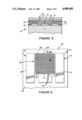
- FIG. 1 illustrates, in top view, a microsensor in accordance with an embodiment of the present invention with an electrode thereon in accordance with an embodiment of the present invention
- FIG. 2 is a sectional view taken along the lines II--II of FIG. 1;
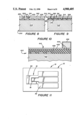
- FIG. 3 is a view similar to FIG. 1 but showing an array of microsensors in accordance with the present invention on a single substrate;
- FIG. 4 is an enlarged partial cross-sectional view taken in the area IV--IV of FIG. 1;
- FIG. 5 is a partial section view of the sensing area of an embodiment in accordance with the invention.
- FIG. 6 is a top view of an embodiment of the present invention.
- FIG. 7 is a view similar to FIG. 6 of an embodiment in accordance with the invention.
- FIG. 8 is a partial section view, of an embodiment in accordance with the invention.
- FIG. 9 is a partial section view of an embodiment in accordance with the invention.
- FIG. 10 is a partial section view of an embodiment in accordance with the invention.
- FIG. 11 is a basic sensor design in accordance with an embodiment in accordance with the invention.
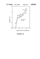
- FIG. 12 is a graphical representation of CO concentration vs. net response
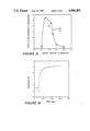
- FIG. 13 is a graphical representation of applied potential vs. net response for 500 ppm CO;
- FIG. 14 is a graphical representation of applied potential vs. background current and response for 500 ppm CO;
- FIG. 15 is a graphical representation of applied potential vs. signal-to-background current ratio
- FIG. 16 is a graphical representation of time vs. response to 500 ppm CO which illustrates response time
- FIG. 17 shows an array of microsensors using a single reference electrode, all on a single substrate.
- the present invention relates to a microsensor 10 as seen in one embodiment in FIG. 1.
- the microsensor 10 includes a substrate 12 having a substrate surface 14 having an active area 16 upon which electrochemical reactions occur.
- the substrate may be made of any of a number of materials.
- the substrate may be made of an insulative material, that is, a dielectric material, such as a non-conducting plastic or glass.
- the substrate can be made of a semiconducting material such as silicon or even of a conducting material so long as an appropriate dielectric material defines the substrate surface 14.
- FIG. 4 shows a substrate 12 which is made of a semiconductor material, namely silicon, and wherein the substrate surface 14 is formed by IC processing techniques of a dielectric material, namely silicon dioxide. Silicon nitride or another insulative material can alternatively be used.
- a first electrode 18 is on the substrate surface 14.
- the first electrode 18 has a sensing portion 20 on the sensing area 16 of the substrate surface 14.
- the sensing portion 20 has an infacing surface 22 (see FIG. 2) facing the substrate surface 14 and an outfacing surface 24 facing away from the substrate surface 14.
- the outfacing surface 24 has an uneven configuration including a plurality of outwardly extending portions 26 (FIG. 4).
- the outwardly extending portions 26 extend outwardly from the outfacing surface 24 preferably from about 0.01 micron to about 5 microns and may be in the nature of hills, ridges, or the like.
- a solid electrolytic medium 28 covers the outfacing surface 24 of the first electrode 18 in such a manner that at least some of the outwardly extending portions 26 of the outfacing surface 24 extend outwardly beyond the electrolytic medium 28 and are not covered thereby.
- the outwardly extending portions 26 of the first electrode 18, the solid electrolytic medium 28 and the surrounding gas phase form a 3-boundary sensing boundary 29 (FIG. 4). Having the outwardly extending portions 26 exposed in this manner leads to an extremely fast response time for the first electrode 18 and also to extremely high sensitivity.
- the solid electrolytic medium is of a thickness upon the outfacing surface of no more than about 10 microns.
- the specific extension of the solid electrolytic medium 28 is a function of the degree of extension of the outwardly extending portion 26 of the outfacing surface 24.
- the criticality of this embodiment lies in having the outwardly extending portions 26 extend upwardly beyond the electroyltic medium 28 to form the 3-phase sensing boundary 29.
- a second (counter) electrode 30 is in contact with the electrolytic medium 28 and free from contact with the first electrode 18.
- the second electrode 30 is upon the substrate surface 14.
- a third (reference) electrode 32 may also be in contact with the electrolytic medium 28 and free from contact with the first electrode 18 and the second electrode 30. Generally, the third electrode 32 will also be in contact with the substrate surface 14.
- the first electrode 18, generally the sensing electrode, the second electrode 30, generally the counter electrode, and the third electrode 32, generally the reference electrode, as well, when present, are adjacent to one another.
- a first-second electrode gap 34 of generally no more than about 50 microns is advantageously present, preferably no more than about 10 microns, more preferably no more than about 5 microns and still more preferably no more than about 2 microns. Indeed, sub-micron (less than about 1 micron) gaps are particularly preferred.
- the gap 36 between the first electrode 18 and the third electrode 32 is conveniently no more than about 100 microns, although this is a far less important restrain and significantly larger gaps can be present.
- the size of the gap 38 between the third electrode 32 and the second electrode 30 is also of no criticality.
- a dielectric wall 40 will generally be present surrounding the active area 16 and the electrolytic medium 28.
- a barrier 42 (FIG. 2) can be present which covers the electrolytic medium 28, the barrier 42 having openings through which an analyte gas can pass.
- the barrier 42 can selectively pass a gaseous species of interest while excluding possibly interfering species.
- the barrier 42 will be in the nature of a polymeric material and more particularly will often be in the nature of a membrane which is gas permeable but aqueous solution impermeable. Note that the membrane need not have actual pores leading to its gas permeable nature.
- the analyte gas may dissolve in the membrane and migrate therethrough to the electrolytic medium.
- the entire microsensor 10 can be inserted in an aqueous solution and dissolved gases therein than form a gas phase, e.g., within the barrier 42 and can be measured. This is the case even if the electrolytic medium abuts the membrane since the analyte is in effect a gas, or gas-like, as it exits the membrane.
- the microsensor 10 can be utilized, for example, in vivo in blood to analyze for blood gases on a continuous basis.
- FIG. 3 illustrates an embodiment of the present invention wherein a plurality of the microsensors 10 are upon the substrate surface 14 of the single substrate 12.
- FIG. 17 illustrates another embodiment of the invention wherein a plurality of the microsensors 10 are upon the substrate surface 14 of the single substrate 12.
- a single reference electrode 32 is used with several different sensing electrodes 18.
- the different sensing electrodes 18 might be made of platinum, platinum oxide, gold and iridium.
- the two counter electrodes 30 are positioned adjacent the sensing electrodes 18.
- the embodiment of FIG. 17 is more compact than, and has the same uses as, the embodiment of FIG. 3.
- An aqueous reservoir 43 (FIG. 2) can be included in the substrate 12 in liquid contact with the electrolytic medium 28 to keep the electrolytic medium 28 from drying out and thereby inactivating the microsensor 10.
- an external aqueous reservoir 456 can alternatively, or additionally, be utilized.
- Such aqueous reservoirs 43,456 can be used in conjunction with all embodiments of the invention.
- the first electrode 18 can be made of any of a number of materials, for example platinum, gold, silver, other platinum group metals, or other desired metals to provide detection of desired species, or electrically conductive polymers.
- the first electrode 18, and along with it the second electrode 30, and the third electrode 32, when present, can be formulated by vapor deposition, sputtering, or the like. Generally, such techniques as are utilized in the IC art are applicable to formulate a microsensor 10 in accordance with the present invention. This can lead to the formation of the controlled size gaps 34,36 and 38, which gaps 34,36,38 can be made quite small in size (below 5 microns and even, with care, below 1 micron).
- the contacts ends 44,46,48 of the electrodes 18,30 and 32, respectively, can be formulated on an appropriate contacts area 50 of the substrate 12.
- FIG. 5 illustrates an embodiment of the present invention wherein the solid electrolytic medium 28 covers the entire outfacing surface 24 of the first (sensing) electrode 18. That is, in the case of the embodiment of FIG. 5 there are no outwardly extending portions 26 of the outfacing surface 24 which extend outwardly beyond the electrolytic medium 28 and are not covered thereby.
- the embodiment of FIG. 5 also gives very fast response time and high sensitivity for gas detection. This is accomplished by providing a plurality of conductive microparticles 52 dispersed in the electrolytic medium 28 and which preferably have at least portions of the uppermost thereof extending outwardly into the gas phase above the
- the outwardly extending microparticles 52 serve as the first electrode 18 and electron conduction occurs from particle to particle down to the bulk portion 18 of the first electrode 18.
- the conductive microparticles 52 might also be of platinum, or might alternatively be of another metal.
- the substrate surface 14 may be roughened so as to provide better adhesion of the first electrode 18 thereto.
- an improvement is set forth in a method of determining the concentration of a particular gaseous species which comprises contacting the species with a sensor having a substrate having a sensing electrode and a reference electrode on a surface thereof, the electrode being covered by a solid electrolytic medium, and measuring the effect of the species on the sensing electrode.
- the improvement comprises a plurality of conductive microparticles 52 dispersed in the electrolytic medium.
- the method may further include providing a counter electrode as the second electrode 30 and utilizing the counter electrode along with the sensing electrode 18, and the reference electrode 32, when measuring the effect.
- the various electrodes 18,30 and 32 are preferably constructed and positioned as set forth above.
- the microsensor structure 110 comprises a substrate 112 having a sensing electrode 114, a counter electrode 116 and a reference electrode 118.
- the electrodes define respective sensing-counter 115, sensing-reference 117 and counter-reference 119 gaps.
- the electrodes 114,116,118 are all mounted on an active area 120 on the surface 122 of the substrate 112.
- the active area 120 is covered with a solid polymer electrolyte 124 which bridges the gaps 115,117,119.
- the solid polymer electrolyte 124 is generally in the form of a relatively thin film.
- sensing electrode 114 and the counter electrode 116 are in the form of interdigited fingers 126,128 having gaps 115 generally no more than about 50 microns and, preferably no more than about 10 microns, still more preferably no more than about 5 microns and still more preferably no more than about 2 microns, with sub-micron (less than 1 micron) gaps being most preferred.
- the reference electrode 118 need not be interdigited with either the sensing electrode 114 or the counter electrode 116.
- inventions of the present invention are in the nature of improved microsensor structures 210,310 (FIGS. 8 and 9) for determining a gaseous species.
- the structures 210,310 comprise a substrate 212,312 having a surface 214,314 having an active area 216,316.
- a first electrode 218,318 and a second electrode 220,320 have respective sensing portions 222,322 and counter portions 224,324 on the active area 216,316.
- a solid electrolytic medium 226,326 covers the sensing area 216,316.
- the improvement in the microsensing structure 210,310 includes positioning the first electrode 218,318 sufficiently close to the second electrode 218,318 so that the time of migration of an ionic moiety, for example hydrogen ion, from one to the other of the first and second electrode 218,318 and 220,320, is no more than about 1 minute.
- the time of migration of the ionic moiety is no more than about 20 seconds, more preferably no more than about 10 seconds.
- the thickness of the electrolytic medium 226,326 is restricted sufficiently so that the time of diffusion of the gaseous species through the electrolytic medium 226,326 to the sensing portion 222,322 of first electrode 218,318 is no more than about equal to the time of migration of the ionic moiety from one to the other of the first and second electrodes. In FIG. 8 this is accomplished via the first electrode 218 extending above the electrolytic medium 226 whereby diffusion time therethrough is zero. In FIG. 9 the electrolytic medium 326 extends only slightly above the first electrode 318 whereby diffusion time is short.
- the limiting factor on the response time of the microsensor structure 210,310 is the rate of migration of the ionic moiety between the electrodes 218,318 and 220,320. It should be recognized that migration of analyte from the environment to the microsensor structure 210,310, or through the barrier 242,342, may in practice be slower than operation of the microsensor structure 210,310.
- the electrodes 218 and 318 are placed close enough together so that the time of ionic migration is very small whereby the overall time of response of the microsensor structure 210,310 is very small.
- the time of diffusion through the electrolytic medium is, in accordance with certain embodiments of the present invention, reduced to zero. This occurs, for example, in the embodiments illustrated in FIGS. 2, 4 and 8. Basically, these Figures show the situation wherein the electrolytic medium 26,226,326, the first electrode, 18,218,318 and the gas phase form a 3-phase sensing boundary. Since there is no diffusion at all through the electrolytic medium, the time of such diffusion is, by definition, zero. In such an instance it is desirable to place the first and second electrodes as close together as possible since the only thing then limiting the response time of the microsensor structure is the time of diffusion of the slowest moving moiety, from one electrode to the other.
- the microsensor includes means for maintaining the solid electrolyte (which requires the presence of water to be functional) in a damp condition.
- the means as illustrated in FIG. 10 comprises providing an overlayer or barrier 442 which covers at least the active area 416 of the microsensor structure 410, the barrier 442 having holes 444 therethrough which communicate with the solid electrolytic medium 426 and further having one or more reservoirs 456 on the opposite side of the barrier 442 from the solid electrolytic medium 426. In this manner, water from the reservoir 456 can pass through the holes 444 and into the solid electrolytic medium 426 thereby keeping the humidity level of the solid electrolytic medium 426 at an acceptable level for extended periods of time.
- the same barrier 442 can be over the remainder of the active area 416 thereby helping to keep down evaporation from the remainder of the solid electrolytic medium 426.
- Appropriate pores 444 can be provided in the barrier 442, as discussed previously with respect to the barrier 42, through which the analyte gaseous species can pass and contact the solid electrolytic medium 426 and/or the sensing electrode 418.
- the barrier 442 would be in the nature of a membrane.
- the membrane can have pores which are generally such as to allow the entrance of a gaseous species but not allow the entrance of a liquid species whereby the microsensor 410 can be utilized to detect a dissolved gaseous species in a liquid by immersing the microsensor 410 beneath the surface of the liquid.
- the analyte gas can dissolve in the barrier 442 and thereby pass therethrough. Note that in this instance the microsensor 410 is still analyzing for a gaseous species since, as discussed elsewhere, only the gaseous species reaches the solid electrolytic medium 426 and/or the sensing electrode 418.
- Another method of keeping the solid electrolyte hydrated is to provide a water absorption overlayer over the solid electrolyte film.
- the analyte gas for example CO and/or CO 2
- the overlayer may be, for example, a hydroscopic polymer such as cellulose acetate butyrate.
- a hydroscopic salt for example lithium chloride and/or lithium bromide, may be incorporated in the solid polymer electrolyte film.
- Specially selected solid polymer electrolyte films may be used which are themselves hydroscopic or which have a particularly high density of sulfonate groups.
- An example is poly(sodium 4-styrenesulfonate), [--CH 2 CH(C 6 H 4 SO 3 Na)--] n .
- This polymer is very hydrophilic whereby signals from the sensor are made humidity independent.
- This particular polymer may also have its property tailored, for example by mixing with Nafion (a trademark of DuPont) polymer, so as to assure that it is not too hydrophilic or too fragile to stick to a substrate. Such techniques as are discussed above serves to make a solid polymer electrolyte film highly proton conductive or sodium conductive.
- the sensing electrode may be a platinum electrode.
- the film of the solid polymer electrolyte may be first deposited on the platinum electrode followed by a platinization process so that ultra-fine platinum particles are dispersed three-dimensionally throughout the solid polymer electrolyte layer.
- the platinization process is conducted prior to the pretreatment of the solid polymer electrolyte, for example the acidification and preoxidation thereof.
- the platinization is carried out using a galvanostatic pulse typically consisting of --3 k mA/cm 2 (cathodic) for one second and +1.5 mA/cm 2 (anodic) for 0.5 seconds in approximately 2 molar H 2 PtCl 6 at room temperature.
- the right value of the current density must be chosen (depending on the gap size, the degree of surface roughness and the specific resistance and thickness of the solid polymer electrolyte) to avoid bridging (short-circuiting) sensing and counter electrodes; for example. If the thickness of the solid polymer electrolyte film is approximately 1 micron, about 3 to 4 hours (a total of about 1.1 to 1.9 coulombs) is required to deposit an adequate amount of platinum.
- the electrolytic medium 28 can be a solution, e.g., a water based solution.
- the electrolytic medium 28 can be a hydrogel.
- solid electrolytes including solid polymeric electrolytes such as Nafion (a trademark of DuPont) which is part of a class of solid polymeric ion exchangers which conduct ions upon exposure to water.
- membranes made from polystyrene with fixed negative sites (sulfonate, carboxylate or phosphonate) or fixed positive sites (quaternary ammonium or quaternary phosphonium).
- Such polymers are characterized chemically and physically in that they have a hydrophobic nature with ionic (hydrophilic) clusters inside. They conduct ions upon hydration. They exclude co-ions up to the Donnan failure point at which stage ions of both types can penetrate into the resin. Neutral molecules can diffuse readily through such membranes and especially large organic molecules can dissolve within the more hydrophobic resins.
- Resins can also be used as reference solutions (see, for example, French patent publication No. 2,158,905). These ion exchange resins have been used as the electrolytic medium for a potentiometric CO 2 sensor (see, for example, U.S. Pat. No. 3,730,868).
- Useful gels for incorporation within the sensor structure include, without limitation: methylcellulose, polyvinyl alcohol, agar, carboxycellulose, gelatin, agarose, deionized gelatin, polyacrylamide, polyvinyl pyrrolidone, polyhydroxyethylacrylate, poly-2-hydroxyethyl methacrylate, and polyacrylic acid. They are characterized in that they constitute thickened (more viscous) solutions. They are hydrophilic in natural and include synthetic polymeric film forming materials.
- the electrolytic medium can alternatively be selected from a family of inorganic oxide solid proton conductors, e.g., hydrogen uranyl phosphate, protonated ⁇ "-alumina, zirconium phosphates or antimonic acids.
- a family of inorganic oxide solid proton conductors e.g., hydrogen uranyl phosphate, protonated ⁇ "-alumina, zirconium phosphates or antimonic acids.
- Means (e.g., the barrier 42) is usually provided for encapsulating the electrolytic medium 28 and the sensing electrode 18.
- the barrier 42 can be any convenient polymer. It is generally preferred that the encapsulation material be such as to be impermeable to water vapor so that the water content of the solid electrolyte remains relatively constant whereby the properties of the gas sensor remain relatively constant with time.
- the barrier 42 may be, for example, in the nature of a membrane. The barrier 42 provides entry into the microsensor 10 of a selected moiety in response to contact of a selected species with its outfacing surface 43.
- the barrier 42 is generally at least substantially impermeable to the electrolytic medium 28 to prevent escape and/or mixing with any analyte solution exterior of the barrier 42.
- the barrier 42 may encapsulate the entire microsensor 10. Alternatively, the barrier 42 may only cover the sensing area 16, or part or all of the substrate surface 14. It may be desirable to encapsulate the remainder of the microsensor 10, or even all of the microsensor 10 including the barrier 42, as a protection against contamination. Generally, an inert encapsulating layer (not shown) will serve the purpose. The encapsulating layer, when present, must provide access (via, for example, pores or holes therethrough) to the barrier 42. It can be formulated as can the barrier 42.
- the barrier 42 can comprise a gas permeable liquid impermeable membrane. This is useful in the situation wherein the sensor is used in a liquid to detect dissolved gases, for example, if the microsensor 10 is utilized in blood.
- teflon membranes silicone rubber membranes, silicon polycarbonate rubber membranes, mylar, nylon 6, polyvinyl alcohol, polyvinyl chloride, methylcellulose, cellulose acetate, high density polyethylene, polystyrene, natural rubber, fluorosilicone, dimethylsilicon rubber, any appropriately perforate photoresist polymer, and dimethylsilicon. It is generally preferred that the membranes utilized be solution castable so as to make fabrication of the membrane more easily accomplished.
- the barrier 42 can be constructed by, for example solution casting, separate casting on a different substrate and physical transfer, heat shrinking in place, solution casting utilizing an ink-jet printer, spin coating, or dip coating. If the barrier 42 is in the nature of uniform latex microspheres, made for example of polystyrene, styrene-butydiene, or Teflon (trademark of DuPont), such microspheres can be placed in position utilizing an ink-jet like technique, by dipping, by solvent spraying, or the like. If the barrier 42 is of the nature of or includes activated carbon or similar materials it can be placed in position by ink-jet type printing, solvent casting, or the like. If the barrier includes, for example, permanganate coated alumina or other substance which serves to remove nitric oxide, it can be placed in position similarly to the carbon particles.
- sensing electrodes 18 can be used. These include, for example, electrodes 18 of platinum, platinum black, silver, gold, iridium, palladium, palladium/silver, iridum dioxide, platinum black/paladium, platinum oxide, and mixtures thereof, electronically conductive polymers, and generally any of the electrodes normally utilized in electrochemical measurements.
- a sensing electrode 18 will generally be chosen which is responsive to a particular gaseous species.
- Various conventional materials can be utilized as the counter electrode 30 and as the reference electrode 32. Table 1 sets forth, as examples only, a short list of gases, and electrochemical systems which have been used to determine them.
- an improvement is set forth in a method of determining the concentration of a particular gaseous species which comprises contacting the species with a sensor having a substrate having a sensing electrode and a reference electrode on a surface thereof, the electrode being covered by a solid electrolytic medium, and measuring the electrochemical effect of the species on the sensing electrode.
- the improvement comprises utilizing as the sensing electrode a first electrode 18 as described in any of the embodiments above.
- the method may further include providing a counter electrode as the second electrode 30, all as set forth above, and utilizing the counter electrode 30 along with the sensing electrode 18 and the reference electrode 32 when measuring the electrochemical effect.
- the various electrodes 18, 30 and 32 are preferably constructed and positioned as set forth above.
- the microsensors 10,110,210,310 and, 410 in accordance with the invention can be constructed, generally, following the techniques of the IC industry.
- the metals can be deposited by sputtering or evaporation, electron-beam or ohmic evaporation onto a resist masked substrate 12 or by a lift-off technique. These techniques are particularly useful for providing closely placed sensing electrodes 18 and counter electrodes 30, such as the fingers 126,128 as shown in FIGS. 7 and 8 with very small gaps 115.
- Solid polymer electrolytes when used, can be provided by using lift off technology or ink-jet printer like technology.
- Hydrogels, when used, can be provided as are solid polymer electrolytes.
- the thickness of the electrolytic medium 28 is controlled by
- Sensing electrodes 18 with outwardly extending portions 26 can be formed by any of several techniques.
- the electrode 18 can be fabricated as discussed above followed by a platinization, gold deposition, etc., process, as appropriate, generally similarly to the technique described elsewhere herein for dispersing ultra-fine platinum particles three-dimensionally through a solid polymer electrolyte.
- the solid polymer electrolyte (or other electrolytic medium 28) is only deposited after the platinization, etc., is carried out if outwardly extending portion 26 are desired on a sensing electrode 18.
- the substrate surface 14 is illustrated as being planar it should be recognized that the invention is not limited to such a structure.
- the first electrode 18 usually generally conforms with the substrate surface 14, whatever its shape, planar, spherical, or the like.
- the electrochemical analysis which can be made in accordance with the methods of and/or using the sensors of the present invention includes voltammetric, potentiometric, coloumbic, conductometric and AC analysis.
- the microsensors of the invention can be used for differential pulse voltammetry (DPV) methods.
- DPV differential pulse voltammetry
- a technique potential is scanned and the resultant current response is differentiated, thereby generating more information from a single sensor.
- the use of the DPV technique to achieve required selectivity is a direct application of the characteristic thermodynamic potentials of the gases being analyzed.
- gases of interest for example CO, H 2 , C 2 H 5 OH, NO, and NO 2
- each reaction requires an additional potential called overpotential, the amount of which depends on electrocatalyst, in order to proceed at a measurable rate.
- thermodynamic potential e.g., CO, H 2 and C 2 H 5 OH.
- gas A and gas B will exhibit current vs potential curves with different limiting currents I A and I B .
- I A and I B By differentiating the current versus potential curves one obtains two sharp, clearly separated peaks with characteristic potentials, E A and B B .
- the peak current values are proportional to the gas concentrations.
- the DPV technique can provide the potential-control led selectivity for a microsensor through precise measurements of the peak values. These are closely related to the thermodynamic potentials of the gases and are characteristics of each gaseous species.
- this technique allows the microelectrochemical sensor to rezero the background several times each second, thereby limiting any background drift. Also, this technique improves the sensitivity because the DPV current readout eliminates most of the capacitive charging current and provides an especially good signal to noise ratio.
- the experimental setup included a microprocessor-controlled gas-handling system (Tylan Co.). Premixed gas mixtures, 200 ppm CO in air, 100 ppm NO 2 in air, 100 ppm NO in N 2 , 1000 ppm ethanol in N 2 (primary standard grade, manufactured by Union Carbide Company Linde Division, South San Francisco, Calif., and distributed by Almac Cryogenic, Inc.), were used to evaluate the microelectronic gas sensors, and hydrocarbon-free air was used as a blank (background) gas. The sample gas (200 ppm CO) and the blank gas (air or N 2 ) were introduced to a stainless-steel gas-sensor chamber at a nominal flow rate of 150 cm 3 /min using flowmeters.
- the sensor potential is controlled by a PAR Model 173 potentiostat equipped with a PAR Model 175 Universal Programmer.
- a PAR Model 173 potentiostat equipped with a PAR Model 175 Universal Programmer.
- an in-vivo voltammograph Bioanalytical Systems, Inc. Model CV 37
- a (Hewlett-Packard Model 7644A) X-Y-t recorder records signals as a function of time.
- Humidified gas samples were prepared as needed by passing dry gas samples through a humidifier prior to entering the gas chamber.
- the humidifier comprises three Gore-Tex (Type A, 3 mm ID, pore size 2 ⁇ m, porosity 50 percent) porous Teflon tubes with three different lengths, approximately 1, 2 and 3 cm, which are equilibrated with water vapor pressure at room temperature, and provide approximate humidity values of 10 to 15, 20 to 25 and 35 to 40 percent relative humidity (RH), respectively.
- the relative humidity of the gas mixture was determined by placing a humidity sensor (General Eastern Instruments Corp. Model 800B humidity and temperature indicator) in the gas line right after the gas chamber.
- the responses to CO and various other gases were studied using a planar type microelectrode.
- the basic sensor design is shown in FIG. 11.
- the masks are designed to produce gaps that range in size from 5 to 50 microns between adjacent microelectrodes.
- a smooth Al 2 O 3 ceramic (Kyocera type A 493) was used as the substrate. Platinum was used as electrode material for all electrodes.
- the metallized substrate was then coated with about 3 ⁇ m of EM Industries' negative polyimide photoresist and photolithographically patterned.
- the polyimide was prebaked at 65° C. for 15 minutes and postbaked at 140° C. for 60 minutes.
- the unwanted portions of the platinum film was etched away by Ar + sputtering-etching techniques.
- the remaining photoresist was then removed by an oxygen plasma etching process.
- the film was dried at room temperature from about 2 hours.
- the Nafion film was then acidified in a beaker containing 20% H 2 SO 4 at approximately 60° C. for about 3 hours.
- FIG. 12 indicates steady-state signals (i s ) as function of CO concentration at an applied potential of -50 mv.
- the sensor was tested in the CO concentration range of 100 to 500 ppm on a planar type platinum sensor with a 10 micron gap between adjacent electrodes. A reasonable linearity is seen.
- FIGS. 13, 14 and 15 illustrate the net response (i s ), background current (i b ), and total signal (i s +i b ), and the values of the signal to background current ratio (i s /i b ), as a function of the applied potential (sensing electrode potential vs. the built-in platinum reference electrode) at 45% RH (relative humidity), respectively.
- the net response is defined as the difference in the measured currents when the sensor is exposed to air (background current) and to 500 ppm CO.
- FIG. 16 shows the current responses to CO as a function of time at an applied potential of -0.05 V (the response time to 500 ppm CO in air is about 1 minute).
- the sensor responses to other gases such as ethanol (800 ppm in air), H 2 (800 ppm in air), NO (80 ppm in air), and NO 2 (100 ppm in air) were also studied.
- Tables 2, 3, 4 and 5 show the current response to 500 ppm CO, 800 ppm ethanol, 80 ppm NO, and 100 ppm NO 2 , respectively, as a function of the applied potential.
- -0.05 V is the most ideal potential for CO sensing because the CO response was very stable and the response time very fast.
- the response to ethanol vapor was unstable and non-reproducible.
- the sensor response to H 2 in the same potential range was also measured, and unstable current response occurred throughout the range.
- the pre-selected applied potential the CO sensor exhibited good response to CO and to a large extent can exclude interfering gases.
- the present invention provides a novel electrode structure 18, a novel microsensor 10, and an improved method of determining the concentration of gaseous species. All of the above is useful in analyzing for any one gaseous species among other gaseous species, or, in accordance with certain embodiments, with gaseous species which are dissolved in a fluid, for example a body fluid such as blood. Extremely fast response time is provided along with extremely high sensitivity. Uses include the following: portable environmental gas analyzers, detection of hazardous gases, fire alarms, gas leak detectors, monitoring and controlling chemical processes, alarm badges for safety inspectors, monitoring and regulating exhaust gases from engines, oil furnaces or industrial burners, control of indoor air quality, and gas chromatography detector, among others. And, construction is relatively inexpensive utilizing standard IC techniques.
Abstract
Description
                                  TABLE 1
__________________________________________________________________________
                                 Sensitivity
Gas Electrocatalyst
             Electrolyte
                      Potential  (Detection Limit*)
__________________________________________________________________________
CO  Platinum-catalyzed
             3.4 M H.sub.2 SO.sub.4
                      1.2 V vs. NHE
                                 10 μA/ppm
    Teflon-bonded                (0.2 ppm)
    diffusion electrode
CO  Platinoid black
             Hydrated solid
                      1.15 V vs. NHE
                                 2.2 μA/ppm
    catalyst with
             polymer (Nafion)    (0.9 ppm)
    Teflon binder
(CO)
    Gold-catalyzed
             4 M H.sub.2 SO.sub.4
                      (1.4 V vs. NHE)
                                 (0.03 μA/ppm)
    Teflon-bonded
    diffusion electrode
NO  Gold catalyzed
             4 M H.sub.2 SO.sub.4
                      >1.2 V vs. NHE
                                 7 μA/ppm
    Teflon-bonded                (0.3 ppm)
NO  Graphite with
             Hydrated solid
                      1.25 V vs. NHE
                                 2.6 μA/ppm
    Teflon binder
             polymer (Nafion)    (0.8 ppm)
NO.sub.2
    Graphite with
             Hydrated solid
                      0.75 V vs. NHE
                                 -2.9 μA/ppm
    Teflon binder
             polymer (Nafion)    (0.7 ppm)
NO.sub.2
    Gold-catalyzed
             4 M H.sub.2 SO.sub.4
                      <1.0 V vs. NHE
                                 -8 μA/ppm
    Teflon-bonded                (0.25 ppm)
    diffusion electrode
H.sub.2 S
    Gold-catalyzed
             28% H.sub.2 SO.sub.4
                      1.45 V vs. NHE
                                 46 μA/ppm
    Teflon-bonded                (40 ppb)
    diffusion electrode
N.sub.2 H.sub.4
    Gold-catalyzed
             23% KOH  1.1 V vs. NHE
                                 40 μA/ppm
    Teflon-bonded                (50 ppb)
    diffusion electrode
CH.sub.4
    Teflon-bonded
             2 M NaClO.sub.4 in
                      0.8 V vs. Ag/AgCl
                                 1 μA % CH.sub.4
    platinum black
             γ-butyrolactane
                                 (3000 ppm)
    electrode
O.sub.2
    Gold (cathode)
             Alkaline -0.6 to -1.0 V
                                 0.05 μA/% O.sub.2
                      vs. Ag/Ag.sub.2 O anode**
                                 (0-100% O.sub.2)
O.sub.2
    Ultrathin
             Alkaline Lead anode**
                                 2.5-3 nA/ppm O.sub.2
    electrode (gold?)            (0.1 ppm to 100%
                                 O.sub.2)
H.sub.2
    Platinum black
             Antimonic acid
                      Platinum black
                                 50 μA/% H.sub.2
    powder            counter electrode**
                                 (400 ppm)
__________________________________________________________________________
 *Detection limit (minimum detectable quantity) is calculated as the value
 yielding a signalto-noise ratio of 2, using a typical noise level 1 μA
 of amperometric gas sensors.
 **Quasiamperometric (polargraphic), no reference.
 NHE = normal hydrogen electrode.
              TABLE 2
______________________________________
Applied    i(b)     i(s)
Potential  nA       nA         i(s)/(b)
                                     Rt(s)
______________________________________
-0.1       -17.9    5.8        0.34  60
-0.05      -0.8     4.3        5.4   58
0.0        -0.9     3.5        3.9   60
+0.03      1.0      4.5        4.5   60
+0.05      .97      2.5        2.6   90
+0.1       3.3      2.2        0.67  60
+0.2       12.5     3.2        0.26  40
______________________________________
 Current Response to 500 ppm CO as a function of Applied Potential
 RH = 45%
              TABLE 3
______________________________________
Applied   i(b)     i(s)
Potential nA       nA        i(s)/(b)
                                   Rt(s)
______________________________________
-0.1      -19.8    138       7.0   60
-0.05     -27      195       7.2   40
0.0       -0.3     75        250   65
+0.03     0.9      100       111   120
+0.05     1.0      180       106   168
+0.1      4.0      232.5     58.1  180
+0.2      13.0     212.5     16.3  80
______________________________________
 Current Response to 800 ppm EtOH as a function of Applied Potential
 RH = 45%
              TABLE 4
______________________________________
Applied   i(b)     i(s)
Potential nA       nA         i(s)/(b)
                                    Rt(s)
______________________________________
-0.1      --       --         --    --
-0.05     -21.0    -18.0      0.86  180
0.0       0.7      -3.7       5.3   180
+0.03     3.9      7.4        1.9   220
+0.05     5.5      17.6       3.2   320
+0.1      7.4      30.0       4.1   300
+0.2      4.9      100.0      20.0  60
______________________________________
 Current Response to 80 ppm NO as a function of Applied Potential
 RH = 45%
              TABLE 5
______________________________________
Applied    i(b)    i(s)
Potential  nA      nA        i(s)/(b)
                                   Rt(s)
______________________________________
-0.1       --      --        --    --
-0.05      -2.1    -7.7      3.7   40
0.0        -1.0    9.5       5.5   60
+0.03      5.2     26.0      5.0   220
+0.05      8.0     56.0      7.0   145
+0.1       29.0    136.0     4.7   230
+0.2       --      --        --    --
______________________________________
 Current Response to 100 ppm NO.sub.2 as a function of Applied Potential
 RH = 45%
Claims (88)
Priority Applications (3)
| Application Number | Priority Date | Filing Date | Title |
|---|---|---|---|
| US07/073,712 US4900405A (en) | 1987-07-15 | 1987-07-15 | Surface type microelectronic gas and vapor sensor |
| JP63177956A JPS6488354A (en) | 1987-07-15 | 1988-07-15 | Surface type microelectronic gas and steam sensor |
| EP19880306481 EP0299780A3 (en) | 1987-07-15 | 1988-07-15 | Surface type microelectronic gas and vapor sensor |
Applications Claiming Priority (1)
| Application Number | Priority Date | Filing Date | Title |
|---|---|---|---|
| US07/073,712 US4900405A (en) | 1987-07-15 | 1987-07-15 | Surface type microelectronic gas and vapor sensor |
Publications (1)
| Publication Number | Publication Date |
|---|---|
| US4900405A true US4900405A (en) | 1990-02-13 |
Family
ID=22115338
Family Applications (1)
| Application Number | Title | Priority Date | Filing Date |
|---|---|---|---|
| US07/073,712 Expired - Fee Related US4900405A (en) | 1987-07-15 | 1987-07-15 | Surface type microelectronic gas and vapor sensor |
Country Status (3)
| Country | Link |
|---|---|
| US (1) | US4900405A (en) |
| EP (1) | EP0299780A3 (en) |
| JP (1) | JPS6488354A (en) |
Cited By (88)
| Publication number | Priority date | Publication date | Assignee | Title |
|---|---|---|---|---|
| WO1990015323A1 (en) * | 1989-06-02 | 1990-12-13 | Sri International | Surface type microelectronic gas and vapor sensor |
| US5004700A (en) * | 1983-08-19 | 1991-04-02 | Emi Limited | Humidity sensor |
| US5045828A (en) * | 1989-07-27 | 1991-09-03 | Texas Instruments Incorporated | Fluoropolymer humidity sensors |
| US5120420A (en) * | 1988-03-31 | 1992-06-09 | Matsushita Electric Industrial Co., Ltd. | Biosensor and a process for preparation thereof |
| US5215643A (en) * | 1988-02-24 | 1993-06-01 | Matsushita Electric Works, Ltd. | Electrochemical gas sensor |
| US5228974A (en) * | 1989-04-29 | 1993-07-20 | Dragerwerk Aktiengesellschaft | Electrochemical measuring cell for determining ammonia or hydrazine in a measuring sample |
| US5273640A (en) * | 1990-06-11 | 1993-12-28 | Matsushita Electric Works, Ltd. | Electrochemical gas sensor |
| US5304293A (en) * | 1992-05-11 | 1994-04-19 | Teknekron Sensor Development Corporation | Microsensors for gaseous and vaporous species |
| US5320722A (en) * | 1987-09-25 | 1994-06-14 | Miller John B | Electro-chemical method for minimizing or preventing corrosion of reinforcement in concrete, and related apparatus |
| US5320733A (en) * | 1990-12-21 | 1994-06-14 | Ultrakust Electronic Gmbh | Sensor system |
| US5322602A (en) * | 1993-01-28 | 1994-06-21 | Teledyne Industries, Inc. | Gas sensors |
| WO1994019683A1 (en) * | 1993-02-25 | 1994-09-01 | Diametrics Medical, Inc. | Disposable electrochemical measurement cartridge |
| US5344546A (en) * | 1989-04-29 | 1994-09-06 | Dragerwerk Aktiengesellschaft | Electrical measuring cell for determinging ammonia, amines, hydrazine amines, hydrazine and hydrazine derivatives |
| US5389224A (en) * | 1993-07-01 | 1995-02-14 | Ford Motor Company | Capacitive A/F sensor |
| EP0701123A1 (en) | 1994-09-10 | 1996-03-13 | United Kingdom Atomic Energy Authority | Formaldehyde vapour detector |
| US5554269A (en) * | 1995-04-11 | 1996-09-10 | Gas Research Institute | Nox sensor using electrochemical reactions and differential pulse voltammetry (DPV) |
| US5563339A (en) * | 1995-02-24 | 1996-10-08 | Southwest Research Institute | Self-correcting autocalibrating vapor pressure analyzer |
| US5670031A (en) * | 1993-06-03 | 1997-09-23 | Fraunhofer-Gesellschaft Zur Angewandten Forschung E.V. | Electrochemical sensor |
| US5716506A (en) * | 1995-10-06 | 1998-02-10 | Board Of Trustees Of The University Of Illinois | Electrochemical sensors for gas detection |
| US5876578A (en) * | 1996-07-12 | 1999-03-02 | Mitsubishi Denki Kabushiki Kaisha | Gas sensor |
| US5911872A (en) * | 1996-08-14 | 1999-06-15 | California Institute Of Technology | Sensors for detecting analytes in fluids |
| US6010616A (en) * | 1995-03-27 | 2000-01-04 | California Institute Of Technology | Sensor arrays for detecting analytes in fluids |
| US6027760A (en) * | 1997-12-08 | 2000-02-22 | Gurer; Emir | Photoresist coating process control with solvent vapor sensor |
| US6170318B1 (en) | 1995-03-27 | 2001-01-09 | California Institute Of Technology | Methods of use for sensor based fluid detection devices |
| WO2001036956A1 (en) * | 1999-11-19 | 2001-05-25 | Perkinelmer Instruments Llc | Hybrid film type sensor |
| WO2001036957A1 (en) * | 1999-11-19 | 2001-05-25 | Perkinelmer Instruments Llc | Film type solid polymer ionomer sensor and sensor cell |
| US6287451B1 (en) | 1999-06-02 | 2001-09-11 | Handani Winarta | Disposable sensor and method of making |
| US6398945B1 (en) | 1999-07-22 | 2002-06-04 | Infrastructure Repair Technologies, Inc. | Method of treating corrosion in reinforced concrete structures by providing a uniform surface potential |
| WO2002046740A1 (en) * | 2000-12-05 | 2002-06-13 | Bill Hoagland | Hydrogen gas indicator system |
| US6416651B1 (en) * | 1999-02-26 | 2002-07-09 | Honeywell Measurex | Multi-electrode composition measuring device and method |
| US20020121439A1 (en) * | 2000-11-13 | 2002-09-05 | Crumly William R. | Electrochemical microsensor package |
| US20030055360A1 (en) * | 2001-09-05 | 2003-03-20 | Zeleznik Matthew A. | Minimally invasive sensing system for measuring rigidity of anatomical matter |
| US20030076082A1 (en) * | 2001-10-23 | 2003-04-24 | Morgan Wayne A. | Implantable sensor electrodes and electronic circuitry |
| US20030087453A1 (en) * | 2000-09-12 | 2003-05-08 | Gerd Scheying | Method and device for producing and screening composite arrangements |
| US6572745B2 (en) | 2001-03-23 | 2003-06-03 | Virotek, L.L.C. | Electrochemical sensor and method thereof |
| US6576102B1 (en) | 2001-03-23 | 2003-06-10 | Virotek, L.L.C. | Electrochemical sensor and method thereof |
| US20030111357A1 (en) * | 2001-12-13 | 2003-06-19 | Black Murdo M. | Test meter calibration |
| US20030164312A1 (en) * | 1999-11-19 | 2003-09-04 | Prohaska Otto J. | Method and apparatus for enhanced detection of a specie using a gas chromatograph |
| US20030169426A1 (en) * | 2002-03-08 | 2003-09-11 | Peterson Timothy A. | Test member orientation |
| KR20030078466A (en) * | 2002-03-29 | 2003-10-08 | 박태업 | humidity sensing materials and manufacturing method for humidity sensing film using the same |
| US20040026267A1 (en) * | 2002-02-28 | 2004-02-12 | Thomas Brinz | Sensor for determining gases and method of manufacturing same |
| US20040061841A1 (en) * | 2002-07-11 | 2004-04-01 | Black Murdo M. | Enzyme electrodes and method of manufacture |
| US20040099211A1 (en) * | 2001-01-22 | 2004-05-27 | Tapio Makela | Layered structure, sensor and method of producing and use of the same |
| US20040171921A1 (en) * | 1998-04-30 | 2004-09-02 | James Say | Analyte monitoring device and methods of use |
| US6787047B1 (en) | 1997-03-13 | 2004-09-07 | Robert Bosch Gmbh | Methods for manufacturing a microstructured sensor |
| US20040178216A1 (en) * | 2003-01-14 | 2004-09-16 | David Brickwood | Sensor dispensing device |
| US20040224369A1 (en) * | 2002-04-19 | 2004-11-11 | Xiaohua Cai | Disposable sensor with enhanced sample port inlet |
| WO2004065129A3 (en) * | 2003-01-16 | 2004-11-25 | Perkinelmer Las Inc | Electrochemical sensor having improved response time |
| US20050014051A1 (en) * | 2003-06-12 | 2005-01-20 | Loutfy Raouf O. | Fullerene-based electrolyte for fuel cells |
| US20050042148A1 (en) * | 1999-11-19 | 2005-02-24 | Prohaska Otto J. | Method and apparatus for improved gas detection |
| US6908537B2 (en) * | 2001-10-22 | 2005-06-21 | Perkinelmer Instruments Llc | Electrochemical sensors having nonporous working electrode |
| US20050150763A1 (en) * | 2004-01-09 | 2005-07-14 | Butters Colin W. | Biosensor and method of manufacture |
| US20050158457A1 (en) * | 2003-12-05 | 2005-07-21 | Thomas Brinz | Sensor for determining gases and method for manufacturing the sensor |
| US6936147B2 (en) * | 1999-11-19 | 2005-08-30 | Perkinelmer Las, Inc. | Hybrid film type sensor |
| US6955750B2 (en) * | 2001-10-22 | 2005-10-18 | Perkinelmer Instruments Llc | Electrochemical sensor compensated for relative humidity |
| US20050241939A1 (en) * | 2001-10-22 | 2005-11-03 | Perkinelmer Las | Method and apparatus for providing and electrochemical gas sensor having a porous electrolyte |
| US20060024546A1 (en) * | 2003-06-12 | 2006-02-02 | Mc Research & Innovation Corp And Mer Corporation | Fullerene-based electrolyte for fuel cells |
| US6997343B2 (en) | 2001-11-14 | 2006-02-14 | Hypoguard Limited | Sensor dispensing device |
| US20060189863A1 (en) * | 1998-04-30 | 2006-08-24 | Abbott Diabetes Care, Inc. | Analyte monitoring device and methods of use |
| US20060249401A1 (en) * | 2003-06-12 | 2006-11-09 | Mirko Lehmann | apparatus and method for determining a chemical element |
| US20070179370A1 (en) * | 1998-04-30 | 2007-08-02 | Abbott Diabetes Care, Inc. | Analyte Monitoring Device and Methods of Use |
| US20070295084A1 (en) * | 2006-06-23 | 2007-12-27 | Fego Precision Industrial Co., Ltd. | Humidity sensor capable of self-regulating temperature compensation and manufacturing method thereof |
| US20080048822A1 (en) * | 2004-10-18 | 2008-02-28 | Senmatic A/S | Humidity Sensor and a Method for Manufacturing the Same |
| WO2008033419A2 (en) * | 2006-09-14 | 2008-03-20 | Agency For Science, Technology And Research | Electrochemical sensor with interdigitated microelectrodes and conducted polymer |
| US20080086039A1 (en) * | 2001-01-02 | 2008-04-10 | Abbott Diabetes Care, Inc. | Analyte Monitoring Device And Methods Of Use |
| WO2008073167A2 (en) * | 2006-08-24 | 2008-06-19 | The University Of North Carolina At Chapel Hill | Nitric oxide microsensors via fluorosilane-based xerogel membranes |
| US7404882B2 (en) | 1999-11-19 | 2008-07-29 | Perkinelmer Las, Inc. | Film-type solid polymer ionomer sensor and sensor cell |
| US7422646B2 (en) * | 2001-10-22 | 2008-09-09 | Perkinelmer Las, Inc. | Electrochemical sensor with dry ionomer membrane and methodfor making the same |
| US20080217173A1 (en) * | 2004-08-13 | 2008-09-11 | Anaxsys Technology Limited | Gas Sensor |
| EP2026064A2 (en) * | 2007-07-30 | 2009-02-18 | Alphasense Limited | Flue Gas Analyser comprising an electrochemical oxygen sensor |
| WO2010056101A1 (en) * | 2008-11-13 | 2010-05-20 | Advanced Bio-Med Tools Sdn. Bhd. | An oxygen sensor |
| US20100276302A1 (en) * | 2007-02-02 | 2010-11-04 | Burkhard Raguse | Chemiresistor for use in conducting electrolyte solution |
| US20120019258A1 (en) * | 2008-10-22 | 2012-01-26 | Nanoscale Systems Naoss Gmbh | Electrochemical sensor and method for the production thereof |
| US8287454B2 (en) | 1998-04-30 | 2012-10-16 | Abbott Diabetes Care Inc. | Analyte monitoring device and methods of use |
| US8346337B2 (en) | 1998-04-30 | 2013-01-01 | Abbott Diabetes Care Inc. | Analyte monitoring device and methods of use |
| US8465425B2 (en) | 1998-04-30 | 2013-06-18 | Abbott Diabetes Care Inc. | Analyte monitoring device and methods of use |
| US8688188B2 (en) | 1998-04-30 | 2014-04-01 | Abbott Diabetes Care Inc. | Analyte monitoring device and methods of use |
| US8702962B1 (en) * | 2007-05-25 | 2014-04-22 | The United States Of America As Represented By The Administrator Of National Aeronautics And Space Administration | Carbon dioxide gas sensors and method of manufacturing and using same |
| US20150021180A1 (en) * | 2012-08-01 | 2015-01-22 | National Institute For Materials Science | Highly proton-conductive polymer film, method for producing same, and humidity sensor |
| US9066695B2 (en) | 1998-04-30 | 2015-06-30 | Abbott Diabetes Care Inc. | Analyte monitoring device and methods of use |
| US20150355366A1 (en) * | 2014-06-05 | 2015-12-10 | Baker Hughes Incorporated | Devices and methods for detecting chemicals |
| WO2018201135A1 (en) * | 2017-04-28 | 2018-11-01 | The Board Of Trustees Of The Leland Stanford Junior University | Micro-electrochemical sensor |
| US10620151B2 (en) | 2016-08-30 | 2020-04-14 | Analog Devices Global | Electrochemical sensor, and a method of forming an electrochemical sensor |
| US11022579B2 (en) | 2018-02-05 | 2021-06-01 | Analog Devices International Unlimited Company | Retaining cap |
| US11268927B2 (en) | 2016-08-30 | 2022-03-08 | Analog Devices International Unlimited Company | Electrochemical sensor, and a method of forming an electrochemical sensor |
| US11609207B2 (en) | 2020-03-31 | 2023-03-21 | Analog Devices International Unlimited Company | Electrochemical sensor and method of forming thereof |
| WO2023192784A3 (en) * | 2022-03-31 | 2024-02-22 | Yale University | Compact scalable dissolved oxygen sensor |
| US11959876B2 (en) | 2021-05-07 | 2024-04-16 | Analog Devices International Unlimited Company | Retaining cap |
Families Citing this family (23)
| Publication number | Priority date | Publication date | Assignee | Title |
|---|---|---|---|---|
| JPH01216251A (en) * | 1988-02-24 | 1989-08-30 | Matsushita Electric Works Ltd | Electrochemical sensor |
| JP2607631B2 (en) * | 1988-07-26 | 1997-05-07 | 松下電工株式会社 | Electrochemical sensor |
| JPH0236347A (en) * | 1988-07-26 | 1990-02-06 | Matsushita Electric Works Ltd | Electrochemical sensor |
| JPH0236348A (en) * | 1988-07-26 | 1990-02-06 | Matsushita Electric Works Ltd | Electrochemical sensor |
| JPH0287059A (en) * | 1988-09-24 | 1990-03-27 | Matsushita Electric Works Ltd | Electrochemical sensor |
| DE4018597A1 (en) * | 1990-06-09 | 1991-12-12 | Draegerwerk Ag | MEASURING ELECTRODE FOR AN ELECTROCHEMICAL GAS MEASURING CELL |
| FR2695481B1 (en) * | 1992-09-07 | 1994-12-02 | Cylergie Gie | Amperometric measurement device comprising an electrochemical sensor. |
| US5338430A (en) * | 1992-12-23 | 1994-08-16 | Minnesota Mining And Manufacturing Company | Nanostructured electrode membranes |
| GB2290382A (en) * | 1994-03-25 | 1995-12-20 | Univ Cranfield | Electrochemical measurement and reactions in highly-resistive solvents |
| GB9412820D0 (en) * | 1994-06-25 | 1994-08-17 | Siemens Plessey Controls Ltd | Water quality measuring apparatus |
| DE19610115C2 (en) * | 1996-03-14 | 2000-11-23 | Fraunhofer Ges Forschung | Detection of molecules and molecular complexes |
| US6294062B1 (en) | 1998-06-01 | 2001-09-25 | Roche Diagnostics Corporation | Method and device for electrochemical immunoassay of multiple analytes |
| AU6114501A (en) * | 2000-05-03 | 2001-11-12 | Jen Gau Jr | Biological identification system with integrated sensor chip |
| GB0110775D0 (en) * | 2001-05-02 | 2001-06-27 | City Tech | Electrochemical gas sensors |
| JP4879979B2 (en) * | 2005-06-14 | 2012-02-22 | エフ ホフマン−ラ ロッシュ アクチェン ゲゼルシャフト | Method and system for controlling the effects of short circuit failure on coplanar electrochemical sensors |
| GB0601703D0 (en) * | 2006-01-27 | 2006-03-08 | Intellitect Water Ltd | Improvement To The Design And Construction Of Electrochemical Sensors |
| CA2693175A1 (en) * | 2006-07-21 | 2008-01-24 | Anaxsys Technology Limited | Gas sensor |
| GB2440556B (en) * | 2006-07-21 | 2009-06-10 | Asthma Alert Ltd | Gas sensor |
| US8449473B2 (en) | 2006-10-18 | 2013-05-28 | Anaxsys Technology Limited | Gas sensor |
| EP2081018A1 (en) | 2008-01-18 | 2009-07-22 | F.Hoffmann-La Roche Ag | Gas sensor with microporous electrolyte layer |
| US8403861B2 (en) | 2010-09-02 | 2013-03-26 | Anaxsys Technology Limited | Detection of respiratory system lesions |
| EP2453228A1 (en) | 2010-11-10 | 2012-05-16 | F. Hoffmann-La Roche AG | Oxygen sensor with microporous electrolyte coating and partially open covering membrane |
| US9791400B2 (en) | 2011-11-22 | 2017-10-17 | Siemens Healthcare Diagnostics Inc. | Interdigitated array and method of manufacture |
Citations (22)
| Publication number | Priority date | Publication date | Assignee | Title |
|---|---|---|---|---|
| US3247452A (en) * | 1964-08-10 | 1966-04-19 | Union Carbide Corp | Gas sensing device with a gasdepolarizable electrode |
| US3464008A (en) * | 1966-10-19 | 1969-08-26 | Siderurgie Fse Inst Rech | Device for continuously measuring the oxygen content of a molten metal including an electrolytic cell having a solid electrolyte |
| US3703696A (en) * | 1971-11-23 | 1972-11-21 | Gen Electric | Humidity sensor |
| US3820402A (en) * | 1970-07-13 | 1974-06-28 | Gen Electric | Electrical pressure transducer |
| US3891958A (en) * | 1972-09-20 | 1975-06-24 | Matsushita Electric Ind Co Ltd | Humidity sensor |
| US4016308A (en) * | 1975-04-09 | 1977-04-05 | Plessey Incorporated | Humidity sensor, material therefor and method |
| US4076596A (en) * | 1976-10-07 | 1978-02-28 | Leeds & Northrup Company | Apparatus for electrolytically determining a species in a fluid and method of use |
| US4140990A (en) * | 1976-02-18 | 1979-02-20 | U.S. Philips Corporation | Probe for selectively detecting vapors, water vapor in particular |
| US4227984A (en) * | 1979-03-01 | 1980-10-14 | General Electric Company | Potentiostated, three-electrode, solid polymer electrolyte (SPE) gas sensor having highly invariant background current characteristics with temperature during zero-air operation |
| US4228400A (en) * | 1978-03-28 | 1980-10-14 | Research Corporation | Conductometric gas analysis cell |
| US4277323A (en) * | 1979-03-09 | 1981-07-07 | Robert Bosch Gmbh | Electrochemical oxygen sensor, particularly for use in the exhaust system of automotive-type internal combustion engines |
| JPS56150748A (en) * | 1980-04-23 | 1981-11-21 | Ricoh Co Ltd | Manufacture of lamination type electrophotographic receptor |
| US4441073A (en) * | 1980-12-22 | 1984-04-03 | Electric Power Research Institute, Inc. | Resistivity sensor system for detecting faults in sealed gas-insulated electrical apparatus |
| US4492622A (en) * | 1983-09-02 | 1985-01-08 | Honeywell Inc. | Clark cell with hydrophylic polymer layer |
| US4510436A (en) * | 1982-07-15 | 1985-04-09 | Southwest Medical Products, Incorporated | Dielectric measuring systems |
| US4536274A (en) * | 1983-04-18 | 1985-08-20 | Diamond Shamrock Chemicals Company | pH and CO2 sensing device and method of making the same |
| US4571292A (en) * | 1982-08-12 | 1986-02-18 | Case Western Reserve University | Apparatus for electrochemical measurements |
| US4571543A (en) * | 1983-03-28 | 1986-02-18 | Southwest Medical Products, Inc. | Specific material detection and measuring device |
| US4593304A (en) * | 1981-04-20 | 1986-06-03 | Hughes Aircraft Company | Heterostructure interdigital high speed photoconductive detector |
| US4636767A (en) * | 1985-08-21 | 1987-01-13 | The United States Of America As Represented By The Secretary Of The Navy | Mixed semiconductor film device for monitoring gases |
| US4638286A (en) * | 1985-03-26 | 1987-01-20 | Enron Corp. | Reactive gas sensor |
| US4668374A (en) * | 1986-07-07 | 1987-05-26 | General Motors Corporation | Gas sensor and method of fabricating same |
Family Cites Families (3)
| Publication number | Priority date | Publication date | Assignee | Title |
|---|---|---|---|---|
| DE2621676C3 (en) * | 1976-05-15 | 1979-01-11 | Bayer Ag, 5090 Leverkusen | Electrochemical gas detector for the detection of gas traces |
| US4171253A (en) * | 1977-02-28 | 1979-10-16 | General Electric Company | Self-humidifying potentiostated, three-electrode hydrated solid polymer electrolyte (SPE) gas sensor |
| US4123700A (en) * | 1977-11-14 | 1978-10-31 | General Electric Company | Potentiostated, self-humidifying, solid polymer electrolyte carbon monoxide dosimeter |
-
1987
- 1987-07-15 US US07/073,712 patent/US4900405A/en not_active Expired - Fee Related
-
1988
- 1988-07-15 JP JP63177956A patent/JPS6488354A/en active Pending
- 1988-07-15 EP EP19880306481 patent/EP0299780A3/en not_active Withdrawn
Patent Citations (22)
| Publication number | Priority date | Publication date | Assignee | Title |
|---|---|---|---|---|
| US3247452A (en) * | 1964-08-10 | 1966-04-19 | Union Carbide Corp | Gas sensing device with a gasdepolarizable electrode |
| US3464008A (en) * | 1966-10-19 | 1969-08-26 | Siderurgie Fse Inst Rech | Device for continuously measuring the oxygen content of a molten metal including an electrolytic cell having a solid electrolyte |
| US3820402A (en) * | 1970-07-13 | 1974-06-28 | Gen Electric | Electrical pressure transducer |
| US3703696A (en) * | 1971-11-23 | 1972-11-21 | Gen Electric | Humidity sensor |
| US3891958A (en) * | 1972-09-20 | 1975-06-24 | Matsushita Electric Ind Co Ltd | Humidity sensor |
| US4016308A (en) * | 1975-04-09 | 1977-04-05 | Plessey Incorporated | Humidity sensor, material therefor and method |
| US4140990A (en) * | 1976-02-18 | 1979-02-20 | U.S. Philips Corporation | Probe for selectively detecting vapors, water vapor in particular |
| US4076596A (en) * | 1976-10-07 | 1978-02-28 | Leeds & Northrup Company | Apparatus for electrolytically determining a species in a fluid and method of use |
| US4228400A (en) * | 1978-03-28 | 1980-10-14 | Research Corporation | Conductometric gas analysis cell |
| US4227984A (en) * | 1979-03-01 | 1980-10-14 | General Electric Company | Potentiostated, three-electrode, solid polymer electrolyte (SPE) gas sensor having highly invariant background current characteristics with temperature during zero-air operation |
| US4277323A (en) * | 1979-03-09 | 1981-07-07 | Robert Bosch Gmbh | Electrochemical oxygen sensor, particularly for use in the exhaust system of automotive-type internal combustion engines |
| JPS56150748A (en) * | 1980-04-23 | 1981-11-21 | Ricoh Co Ltd | Manufacture of lamination type electrophotographic receptor |
| US4441073A (en) * | 1980-12-22 | 1984-04-03 | Electric Power Research Institute, Inc. | Resistivity sensor system for detecting faults in sealed gas-insulated electrical apparatus |
| US4593304A (en) * | 1981-04-20 | 1986-06-03 | Hughes Aircraft Company | Heterostructure interdigital high speed photoconductive detector |
| US4510436A (en) * | 1982-07-15 | 1985-04-09 | Southwest Medical Products, Incorporated | Dielectric measuring systems |
| US4571292A (en) * | 1982-08-12 | 1986-02-18 | Case Western Reserve University | Apparatus for electrochemical measurements |
| US4571543A (en) * | 1983-03-28 | 1986-02-18 | Southwest Medical Products, Inc. | Specific material detection and measuring device |
| US4536274A (en) * | 1983-04-18 | 1985-08-20 | Diamond Shamrock Chemicals Company | pH and CO2 sensing device and method of making the same |
| US4492622A (en) * | 1983-09-02 | 1985-01-08 | Honeywell Inc. | Clark cell with hydrophylic polymer layer |
| US4638286A (en) * | 1985-03-26 | 1987-01-20 | Enron Corp. | Reactive gas sensor |
| US4636767A (en) * | 1985-08-21 | 1987-01-13 | The United States Of America As Represented By The Secretary Of The Navy | Mixed semiconductor film device for monitoring gases |
| US4668374A (en) * | 1986-07-07 | 1987-05-26 | General Motors Corporation | Gas sensor and method of fabricating same |
Non-Patent Citations (4)
| Title |
|---|
| Koudelka et al., Miniaturized "Clark-Type" Oxygen Sensor, Centre Suisse d'Electronique et de, Microtechnique S.A., Neuchatel, Switzerland, CH2127-9/85/0000-0418, 1985, IEEE. |
| Koudelka et al., Miniaturized Clark Type Oxygen Sensor, Centre Suisse d Electronique et de, Microtechnique S.A., Neuchatel, Switzerland, CH2127 9/85/0000 0418, 1985, IEEE. * |
| Koudelka, Performance Characteristics of a Planar "Clark-Type" Oxygen Sensor, 9, (1986), 249-258. |
| Koudelka, Performance Characteristics of a Planar Clark Type Oxygen Sensor, 9, (1986), 249 258. * |
Cited By (224)
| Publication number | Priority date | Publication date | Assignee | Title |
|---|---|---|---|---|
| US5004700A (en) * | 1983-08-19 | 1991-04-02 | Emi Limited | Humidity sensor |
| US5320722A (en) * | 1987-09-25 | 1994-06-14 | Miller John B | Electro-chemical method for minimizing or preventing corrosion of reinforcement in concrete, and related apparatus |
| US5215643A (en) * | 1988-02-24 | 1993-06-01 | Matsushita Electric Works, Ltd. | Electrochemical gas sensor |
| US5120420A (en) * | 1988-03-31 | 1992-06-09 | Matsushita Electric Industrial Co., Ltd. | Biosensor and a process for preparation thereof |
| US5228974A (en) * | 1989-04-29 | 1993-07-20 | Dragerwerk Aktiengesellschaft | Electrochemical measuring cell for determining ammonia or hydrazine in a measuring sample |
| US5344546A (en) * | 1989-04-29 | 1994-09-06 | Dragerwerk Aktiengesellschaft | Electrical measuring cell for determinging ammonia, amines, hydrazine amines, hydrazine and hydrazine derivatives |
| WO1990015323A1 (en) * | 1989-06-02 | 1990-12-13 | Sri International | Surface type microelectronic gas and vapor sensor |
| US5045828A (en) * | 1989-07-27 | 1991-09-03 | Texas Instruments Incorporated | Fluoropolymer humidity sensors |
| US5273640A (en) * | 1990-06-11 | 1993-12-28 | Matsushita Electric Works, Ltd. | Electrochemical gas sensor |
| US5320733A (en) * | 1990-12-21 | 1994-06-14 | Ultrakust Electronic Gmbh | Sensor system |
| US5304293A (en) * | 1992-05-11 | 1994-04-19 | Teknekron Sensor Development Corporation | Microsensors for gaseous and vaporous species |
| US5322602A (en) * | 1993-01-28 | 1994-06-21 | Teledyne Industries, Inc. | Gas sensors |
| EP0609065A2 (en) * | 1993-01-28 | 1994-08-03 | Teledyne Industries, Inc. | Gas sensors |
| EP0609065A3 (en) * | 1993-01-28 | 1995-12-27 | Teledyne Ind | Gas sensors. |
| WO1994019683A1 (en) * | 1993-02-25 | 1994-09-01 | Diametrics Medical, Inc. | Disposable electrochemical measurement cartridge |
| US5670031A (en) * | 1993-06-03 | 1997-09-23 | Fraunhofer-Gesellschaft Zur Angewandten Forschung E.V. | Electrochemical sensor |
| US5389224A (en) * | 1993-07-01 | 1995-02-14 | Ford Motor Company | Capacitive A/F sensor |
| EP0701123A1 (en) | 1994-09-10 | 1996-03-13 | United Kingdom Atomic Energy Authority | Formaldehyde vapour detector |
| US5563339A (en) * | 1995-02-24 | 1996-10-08 | Southwest Research Institute | Self-correcting autocalibrating vapor pressure analyzer |
| US6093308A (en) * | 1995-03-27 | 2000-07-25 | California Institute Of Technology | Sensors for detecting analytes in fluids |
| US6010616A (en) * | 1995-03-27 | 2000-01-04 | California Institute Of Technology | Sensor arrays for detecting analytes in fluids |
| US6017440A (en) * | 1995-03-27 | 2000-01-25 | California Institute Of Technology | Sensor arrays for detecting microorganisms |
| US6170318B1 (en) | 1995-03-27 | 2001-01-09 | California Institute Of Technology | Methods of use for sensor based fluid detection devices |
| US6331244B1 (en) | 1995-03-27 | 2001-12-18 | California Institute Of Technology | Sensors for detecting analytes in fluids |
| US5554269A (en) * | 1995-04-11 | 1996-09-10 | Gas Research Institute | Nox sensor using electrochemical reactions and differential pulse voltammetry (DPV) |
| US5716506A (en) * | 1995-10-06 | 1998-02-10 | Board Of Trustees Of The University Of Illinois | Electrochemical sensors for gas detection |
| US5876578A (en) * | 1996-07-12 | 1999-03-02 | Mitsubishi Denki Kabushiki Kaisha | Gas sensor |
| US5911872A (en) * | 1996-08-14 | 1999-06-15 | California Institute Of Technology | Sensors for detecting analytes in fluids |
| US6787047B1 (en) | 1997-03-13 | 2004-09-07 | Robert Bosch Gmbh | Methods for manufacturing a microstructured sensor |
| US6027760A (en) * | 1997-12-08 | 2000-02-22 | Gurer; Emir | Photoresist coating process control with solvent vapor sensor |
| US8175673B2 (en) | 1998-04-30 | 2012-05-08 | Abbott Diabetes Care Inc. | Analyte monitoring device and methods of use |
| US8734348B2 (en) | 1998-04-30 | 2014-05-27 | Abbott Diabetes Care Inc. | Analyte monitoring device and methods of use |
| US20100268047A1 (en) * | 1998-04-30 | 2010-10-21 | Abbott Diabetes Care Inc. | Analyte Monitoring Device and Methods of Use |
| US20100268049A1 (en) * | 1998-04-30 | 2010-10-21 | Abbott Diabetes Care Inc. | Analyte Monitoring Device and Methods of Use |
| US8391945B2 (en) | 1998-04-30 | 2013-03-05 | Abbott Diabetes Care Inc. | Analyte monitoring device and methods of use |
| US8353829B2 (en) | 1998-04-30 | 2013-01-15 | Abbott Diabetes Care Inc. | Analyte monitoring device and methods of use |
| US8409131B2 (en) | 1998-04-30 | 2013-04-02 | Abbott Diabetes Care Inc. | Analyte monitoring device and methods of use |
| US8357091B2 (en) | 1998-04-30 | 2013-01-22 | Abbott Diabetes Care Inc. | Analyte monitoring device and methods of use |
| US8346337B2 (en) | 1998-04-30 | 2013-01-01 | Abbott Diabetes Care Inc. | Analyte monitoring device and methods of use |
| US10478108B2 (en) | 1998-04-30 | 2019-11-19 | Abbott Diabetes Care Inc. | Analyte monitoring device and methods of use |
| US8465425B2 (en) | 1998-04-30 | 2013-06-18 | Abbott Diabetes Care Inc. | Analyte monitoring device and methods of use |
| US8346336B2 (en) | 1998-04-30 | 2013-01-01 | Abbott Diabetes Care Inc. | Analyte monitoring device and methods of use |
| US8366614B2 (en) | 1998-04-30 | 2013-02-05 | Abbott Diabetes Care Inc. | Analyte monitoring device and methods of use |
| US8306598B2 (en) | 1998-04-30 | 2012-11-06 | Abbott Diabetes Care Inc. | Analyte monitoring device and methods of use |
| US8473021B2 (en) | 1998-04-30 | 2013-06-25 | Abbott Diabetes Care Inc. | Analyte monitoring device and methods of use |
| US8287454B2 (en) | 1998-04-30 | 2012-10-16 | Abbott Diabetes Care Inc. | Analyte monitoring device and methods of use |
| US9326714B2 (en) | 1998-04-30 | 2016-05-03 | Abbott Diabetes Care Inc. | Analyte monitoring device and methods of use |
| US8480580B2 (en) | 1998-04-30 | 2013-07-09 | Abbott Diabetes Care Inc. | Analyte monitoring device and methods of use |
| US9072477B2 (en) | 1998-04-30 | 2015-07-07 | Abbott Diabetes Care Inc. | Analyte monitoring device and methods of use |
| US8273022B2 (en) | 1998-04-30 | 2012-09-25 | Abbott Diabetes Care Inc. | Analyte monitoring device and methods of use |
| US9066695B2 (en) | 1998-04-30 | 2015-06-30 | Abbott Diabetes Care Inc. | Analyte monitoring device and methods of use |
| US8275439B2 (en) | 1998-04-30 | 2012-09-25 | Abbott Diabetes Care Inc. | Analyte monitoring device and methods of use |
| US20040171921A1 (en) * | 1998-04-30 | 2004-09-02 | James Say | Analyte monitoring device and methods of use |
| US20090216101A1 (en) * | 1998-04-30 | 2009-08-27 | Abbott Diabetes Care, Inc. | Analyte Monitoring Device and Methods of Use |
| US9066694B2 (en) | 1998-04-30 | 2015-06-30 | Abbott Diabetes Care Inc. | Analyte monitoring device and methods of use |
| US9066697B2 (en) | 1998-04-30 | 2015-06-30 | Abbott Diabetes Care Inc. | Analyte monitoring device and methods of use |
| US9042953B2 (en) | 1998-04-30 | 2015-05-26 | Abbott Diabetes Care Inc. | Analyte monitoring device and methods of use |
| US8265726B2 (en) | 1998-04-30 | 2012-09-11 | Abbott Diabetes Care Inc. | Analyte monitoring device and methods of use |
| US9014773B2 (en) | 1998-04-30 | 2015-04-21 | Abbott Diabetes Care Inc. | Analyte monitoring device and methods of use |
| US9011331B2 (en) | 1998-04-30 | 2015-04-21 | Abbott Diabetes Care Inc. | Analyte monitoring device and methods of use |
| US8260392B2 (en) | 1998-04-30 | 2012-09-04 | Abbott Diabetes Care Inc. | Analyte monitoring device and methods of use |
| US8255031B2 (en) | 1998-04-30 | 2012-08-28 | Abbott Diabetes Care Inc. | Analyte monitoring device and methods of use |
| US8597189B2 (en) | 1998-04-30 | 2013-12-03 | Abbott Diabetes Care Inc. | Analyte monitoring device and methods of use |
| US8974386B2 (en) | 1998-04-30 | 2015-03-10 | Abbott Diabetes Care Inc. | Analyte monitoring device and methods of use |
| US8235896B2 (en) | 1998-04-30 | 2012-08-07 | Abbott Diabetes Care Inc. | Analyte monitoring device and methods of use |
| US8231532B2 (en) | 1998-04-30 | 2012-07-31 | Abbott Diabetes Care Inc. | Analyte monitoring device and methods of use |
| US8226555B2 (en) | 1998-04-30 | 2012-07-24 | Abbott Diabetes Care Inc. | Analyte monitoring device and methods of use |
| US8880137B2 (en) | 1998-04-30 | 2014-11-04 | Abbott Diabetes Care Inc. | Analyte monitoring device and methods of use |
| US8840553B2 (en) | 1998-04-30 | 2014-09-23 | Abbott Diabetes Care Inc. | Analyte monitoring device and methods of use |
| US8612159B2 (en) | 1998-04-30 | 2013-12-17 | Abbott Diabetes Care Inc. | Analyte monitoring device and methods of use |
| US20090177064A1 (en) * | 1998-04-30 | 2009-07-09 | Abbott Diabetes Care, Inc. | Analyte Monitoring Device and Methods of Use |
| US20090171179A1 (en) * | 1998-04-30 | 2009-07-02 | Abbott Diabetes Care, Inc. | Analyte Monitoring Device and Methods of Use |
| US8774887B2 (en) | 1998-04-30 | 2014-07-08 | Abbott Diabetes Care Inc. | Analyte monitoring device and methods of use |
| US8744545B2 (en) | 1998-04-30 | 2014-06-03 | Abbott Diabetes Care Inc. | Analyte monitoring device and methods of use |
| US8226558B2 (en) | 1998-04-30 | 2012-07-24 | Abbott Diabetes Care Inc. | Analyte monitoring device and methods of use |
| US8226557B2 (en) | 1998-04-30 | 2012-07-24 | Abbott Diabetes Care Inc. | Analyte monitoring device and methods of use |
| US8224413B2 (en) | 1998-04-30 | 2012-07-17 | Abbott Diabetes Care Inc. | Analyte monitoring device and methods of use |
| US8617071B2 (en) | 1998-04-30 | 2013-12-31 | Abbott Diabetes Care Inc. | Analyte monitoring device and methods of use |
| US8738109B2 (en) | 1998-04-30 | 2014-05-27 | Abbott Diabetes Care Inc. | Analyte monitoring device and methods of use |
| US8622906B2 (en) | 1998-04-30 | 2014-01-07 | Abbott Diabetes Care Inc. | Analyte monitoring device and methods of use |
| US8380273B2 (en) | 1998-04-30 | 2013-02-19 | Abbott Diabetes Care Inc. | Analyte monitoring device and methods of use |
| US8641619B2 (en) | 1998-04-30 | 2014-02-04 | Abbott Diabetes Care Inc. | Analyte monitoring device and methods of use |
| US20060189863A1 (en) * | 1998-04-30 | 2006-08-24 | Abbott Diabetes Care, Inc. | Analyte monitoring device and methods of use |
| US8734346B2 (en) | 1998-04-30 | 2014-05-27 | Abbott Diabetes Care Inc. | Analyte monitoring device and methods of use |
| US8372005B2 (en) | 1998-04-30 | 2013-02-12 | Abbott Diabetes Care Inc. | Analyte monitoring device and methods of use |
| US8177716B2 (en) | 1998-04-30 | 2012-05-15 | Abbott Diabetes Care Inc. | Analyte monitoring device and methods of use |
| US8649841B2 (en) | 1998-04-30 | 2014-02-11 | Abbott Diabetes Care Inc. | Analyte monitoring device and methods of use |
| US8660627B2 (en) | 1998-04-30 | 2014-02-25 | Abbott Diabetes Care Inc. | Analyte monitoring device and methods of use |
| US8688188B2 (en) | 1998-04-30 | 2014-04-01 | Abbott Diabetes Care Inc. | Analyte monitoring device and methods of use |
| US20070179370A1 (en) * | 1998-04-30 | 2007-08-02 | Abbott Diabetes Care, Inc. | Analyte Monitoring Device and Methods of Use |
| US20070191699A1 (en) * | 1998-04-30 | 2007-08-16 | Abbott Diabetes Care, Inc. | Analyte Monitoring Device and Methods of Use |
| US20070203411A1 (en) * | 1998-04-30 | 2007-08-30 | Abbott Diabetes Care, Inc. | Analyte Monitoring Device and Methods of Use |
| US20070203410A1 (en) * | 1998-04-30 | 2007-08-30 | Abbott Diabetes Care, Inc. | Analyte Monitoring Device and Methods of Use |
| US8672844B2 (en) | 1998-04-30 | 2014-03-18 | Abbott Diabetes Care Inc. | Analyte monitoring device and methods of use |
| US20070208247A1 (en) * | 1998-04-30 | 2007-09-06 | Abbott Diabetes Care, Inc. | Analyte Monitoring Device and Methods of Use |
| US20070249920A1 (en) * | 1998-04-30 | 2007-10-25 | Abbott Diabetes Care, Inc. | Analyte monitoring device and methods of use |
| US20100274111A1 (en) * | 1998-04-30 | 2010-10-28 | Abbott Diabetes Care Inc. | Analyte Monitoring Device and Methods of Use |
| US20080033271A1 (en) * | 1998-04-30 | 2008-02-07 | Abbott Diabetes Care, Inc. | Analyte monitoring device and methods of use |
| US8670815B2 (en) | 1998-04-30 | 2014-03-11 | Abbott Diabetes Care Inc. | Analyte monitoring device and methods of use |
| US8666469B2 (en) | 1998-04-30 | 2014-03-04 | Abbott Diabetes Care Inc. | Analyte monitoring device and methods of use |
| US8162829B2 (en) | 1998-04-30 | 2012-04-24 | Abbott Diabetes Care Inc. | Analyte monitoring device and methods of use |
| US20080091096A1 (en) * | 1998-04-30 | 2008-04-17 | Abbott Diabetes Care, Inc. | Analyte Monitoring Device and Methods of Use |
| US6416651B1 (en) * | 1999-02-26 | 2002-07-09 | Honeywell Measurex | Multi-electrode composition measuring device and method |
| US6287451B1 (en) | 1999-06-02 | 2001-09-11 | Handani Winarta | Disposable sensor and method of making |
| US6398945B1 (en) | 1999-07-22 | 2002-06-04 | Infrastructure Repair Technologies, Inc. | Method of treating corrosion in reinforced concrete structures by providing a uniform surface potential |
| US20060000723A1 (en) * | 1999-11-19 | 2006-01-05 | Perkinelmer Las | Electrochemical sensor having improved response time |
| US6932941B2 (en) | 1999-11-19 | 2005-08-23 | Perkinelmer Instruments Llc | Method and apparatus for improved gas detection |
| US20060075802A1 (en) * | 1999-11-19 | 2006-04-13 | Perkinelmer, Las | Method and apparatus for enhanced detection of a specie using a gas chromatograph |
| US7429362B2 (en) | 1999-11-19 | 2008-09-30 | Perkinelmer Las, Inc. | Method and apparatus for improved gas detection |
| US20080264789A1 (en) * | 1999-11-19 | 2008-10-30 | Perkinelmer Las, Inc. | Film-Type Solid Polymer Ionomer Sensor And Sensor Cell |
| US7013707B2 (en) | 1999-11-19 | 2006-03-21 | Perkinelmer Las, Inc | Method and apparatus for enhanced detection of a specie using a gas chromatograph |
| US20080293158A1 (en) * | 1999-11-19 | 2008-11-27 | Perkinelmer Las, Inc. | Method And Apparatus For Improved Gas Detection |
| EP1149284A1 (en) * | 1999-11-19 | 2001-10-31 | PerkinElmer Instruments LLC | Film type solid polymer ionomer sensor and sensor cell |
| WO2001036956A1 (en) * | 1999-11-19 | 2001-05-25 | Perkinelmer Instruments Llc | Hybrid film type sensor |
| US7237430B2 (en) | 1999-11-19 | 2007-07-03 | Perkinelmer Las, Inc. | Method and apparatus for enhanced detection of a specie using a gas chromatograph |
| US6936147B2 (en) * | 1999-11-19 | 2005-08-30 | Perkinelmer Las, Inc. | Hybrid film type sensor |
| EP1149284A4 (en) * | 1999-11-19 | 2006-12-13 | Perkinelmer Instruments Llc | Film type solid polymer ionomer sensor and sensor cell |
| US6929735B2 (en) * | 1999-11-19 | 2005-08-16 | Perkin Elmer Instruments Llc | Electrochemical sensor having improved response time |
| US20050042148A1 (en) * | 1999-11-19 | 2005-02-24 | Prohaska Otto J. | Method and apparatus for improved gas detection |
| WO2001036957A1 (en) * | 1999-11-19 | 2001-05-25 | Perkinelmer Instruments Llc | Film type solid polymer ionomer sensor and sensor cell |
| US6682638B1 (en) * | 1999-11-19 | 2004-01-27 | Perkin Elmer Llc | Film type solid polymer ionomer sensor and sensor cell |
| US20030164312A1 (en) * | 1999-11-19 | 2003-09-04 | Prohaska Otto J. | Method and apparatus for enhanced detection of a specie using a gas chromatograph |
| EP1161678A1 (en) * | 1999-11-19 | 2001-12-12 | PerkinElmer Instruments LLC | Hybrid film type sensor |
| EP1161678A4 (en) * | 1999-11-19 | 2007-02-21 | Perkinelmer Instruments Llc | Hybrid film type sensor |
| US7736908B2 (en) | 1999-11-19 | 2010-06-15 | Perkinelmer Las, Inc. | Method and apparatus for improved gas detection |
| US7404882B2 (en) | 1999-11-19 | 2008-07-29 | Perkinelmer Las, Inc. | Film-type solid polymer ionomer sensor and sensor cell |
| US8123923B2 (en) | 1999-11-19 | 2012-02-28 | Perkinelmer Health Sciences, Inc. | Film-type solid polymer ionomer sensor and sensor cell |
| US20030087453A1 (en) * | 2000-09-12 | 2003-05-08 | Gerd Scheying | Method and device for producing and screening composite arrangements |
| US20020121439A1 (en) * | 2000-11-13 | 2002-09-05 | Crumly William R. | Electrochemical microsensor package |
| US6849168B2 (en) | 2000-11-13 | 2005-02-01 | Kval, Inc. | Electrochemical microsensor package |
| US6895805B2 (en) | 2000-12-05 | 2005-05-24 | William Hoagland | Hydrogen gas indicator system |
| WO2002046740A1 (en) * | 2000-12-05 | 2002-06-13 | Bill Hoagland | Hydrogen gas indicator system |
| US20040050143A1 (en) * | 2000-12-05 | 2004-03-18 | William Hoagland | Hydrogen gas indicator system |
| US9610034B2 (en) | 2001-01-02 | 2017-04-04 | Abbott Diabetes Care Inc. | Analyte monitoring device and methods of use |
| US8652043B2 (en) | 2001-01-02 | 2014-02-18 | Abbott Diabetes Care Inc. | Analyte monitoring device and methods of use |
| US20080086039A1 (en) * | 2001-01-02 | 2008-04-10 | Abbott Diabetes Care, Inc. | Analyte Monitoring Device And Methods Of Use |
| US8668645B2 (en) | 2001-01-02 | 2014-03-11 | Abbott Diabetes Care Inc. | Analyte monitoring device and methods of use |
| US9498159B2 (en) | 2001-01-02 | 2016-11-22 | Abbott Diabetes Care Inc. | Analyte monitoring device and methods of use |
| US9011332B2 (en) | 2001-01-02 | 2015-04-21 | Abbott Diabetes Care Inc. | Analyte monitoring device and methods of use |
| US7157134B2 (en) | 2001-01-22 | 2007-01-02 | Metso Corporation | Layered structure, sensor and method of producing and use of the same |
| US20040099211A1 (en) * | 2001-01-22 | 2004-05-27 | Tapio Makela | Layered structure, sensor and method of producing and use of the same |
| US6576102B1 (en) | 2001-03-23 | 2003-06-10 | Virotek, L.L.C. | Electrochemical sensor and method thereof |
| US20050067737A1 (en) * | 2001-03-23 | 2005-03-31 | Craig Rappin | Method of making sensor |
| US6849216B2 (en) | 2001-03-23 | 2005-02-01 | Virotek, L.L.C. | Method of making sensor |
| US6572745B2 (en) | 2001-03-23 | 2003-06-03 | Virotek, L.L.C. | Electrochemical sensor and method thereof |
| US20030055360A1 (en) * | 2001-09-05 | 2003-03-20 | Zeleznik Matthew A. | Minimally invasive sensing system for measuring rigidity of anatomical matter |
| US6955750B2 (en) * | 2001-10-22 | 2005-10-18 | Perkinelmer Instruments Llc | Electrochemical sensor compensated for relative humidity |
| US20080289962A1 (en) * | 2001-10-22 | 2008-11-27 | Perkinelmer Las, Inc. | Electrochemical sensor with dry ionomer membrane |
| US7422646B2 (en) * | 2001-10-22 | 2008-09-09 | Perkinelmer Las, Inc. | Electrochemical sensor with dry ionomer membrane and methodfor making the same |
| US20050269203A1 (en) * | 2001-10-22 | 2005-12-08 | Perkinelmer Las | Electrochemical sensor compensated for relative humidity |
| US20050241939A1 (en) * | 2001-10-22 | 2005-11-03 | Perkinelmer Las | Method and apparatus for providing and electrochemical gas sensor having a porous electrolyte |
| US6908537B2 (en) * | 2001-10-22 | 2005-06-21 | Perkinelmer Instruments Llc | Electrochemical sensors having nonporous working electrode |
| US7887683B2 (en) * | 2001-10-22 | 2011-02-15 | Perkinelmer Health Sciences, Inc. | Electrochemical sensor compensated for relative humidity |
| US7525298B2 (en) | 2001-10-23 | 2009-04-28 | Medtronic Minimed, Inc. | Implantable sensor electrodes and electronic circuitry |
| US6809507B2 (en) * | 2001-10-23 | 2004-10-26 | Medtronic Minimed, Inc. | Implantable sensor electrodes and electronic circuitry |
| US20030076082A1 (en) * | 2001-10-23 | 2003-04-24 | Morgan Wayne A. | Implantable sensor electrodes and electronic circuitry |
| US20090203979A1 (en) * | 2001-10-23 | 2009-08-13 | Medtronic Minimed, Inc. | Implantable sensor electrodes and electronic circuitry |
| US20050056539A1 (en) * | 2001-10-23 | 2005-03-17 | Medtronic-Minimed, Inc. | Implantable sensor electrodes and electronic circuitry |
| US6997343B2 (en) | 2001-11-14 | 2006-02-14 | Hypoguard Limited | Sensor dispensing device |
| US20030111357A1 (en) * | 2001-12-13 | 2003-06-19 | Black Murdo M. | Test meter calibration |
| US20040026267A1 (en) * | 2002-02-28 | 2004-02-12 | Thomas Brinz | Sensor for determining gases and method of manufacturing same |
| US20030169426A1 (en) * | 2002-03-08 | 2003-09-11 | Peterson Timothy A. | Test member orientation |
| KR20030078466A (en) * | 2002-03-29 | 2003-10-08 | 박태업 | humidity sensing materials and manufacturing method for humidity sensing film using the same |
| US6837976B2 (en) | 2002-04-19 | 2005-01-04 | Nova Biomedical Corporation | Disposable sensor with enhanced sample port inlet |
| US20040224369A1 (en) * | 2002-04-19 | 2004-11-11 | Xiaohua Cai | Disposable sensor with enhanced sample port inlet |
| US20040061841A1 (en) * | 2002-07-11 | 2004-04-01 | Black Murdo M. | Enzyme electrodes and method of manufacture |
| US7250095B2 (en) | 2002-07-11 | 2007-07-31 | Hypoguard Limited | Enzyme electrodes and method of manufacture |
| US7264139B2 (en) | 2003-01-14 | 2007-09-04 | Hypoguard Limited | Sensor dispensing device |
| US20040178216A1 (en) * | 2003-01-14 | 2004-09-16 | David Brickwood | Sensor dispensing device |
| WO2004065129A3 (en) * | 2003-01-16 | 2004-11-25 | Perkinelmer Las Inc | Electrochemical sensor having improved response time |
| WO2004065933A3 (en) * | 2003-01-16 | 2005-10-06 | Perkinelmer Las Inc | Method and apparatus for enhanced detection of a specie using a gas chromatograph |
| US20050014051A1 (en) * | 2003-06-12 | 2005-01-20 | Loutfy Raouf O. | Fullerene-based electrolyte for fuel cells |
| US20060024546A1 (en) * | 2003-06-12 | 2006-02-02 | Mc Research & Innovation Corp And Mer Corporation | Fullerene-based electrolyte for fuel cells |
| US20060249401A1 (en) * | 2003-06-12 | 2006-11-09 | Mirko Lehmann | apparatus and method for determining a chemical element |
| US6949304B2 (en) | 2003-06-12 | 2005-09-27 | Mc Research & Innovation Center | Fullerene-based electrolyte for fuel cells |
| US20090205958A1 (en) * | 2003-12-05 | 2009-08-20 | Thomas Brinz | Sensor for determining gases and method for manufacturing the sensor |
| US8758585B2 (en) | 2003-12-05 | 2014-06-24 | Robert Bosch Gmbh | Sensor for determining gases and method for manufacturing the sensor |
| US20050158457A1 (en) * | 2003-12-05 | 2005-07-21 | Thomas Brinz | Sensor for determining gases and method for manufacturing the sensor |
| US20050150763A1 (en) * | 2004-01-09 | 2005-07-14 | Butters Colin W. | Biosensor and method of manufacture |
| US20080217173A1 (en) * | 2004-08-13 | 2008-09-11 | Anaxsys Technology Limited | Gas Sensor |
| US20080048822A1 (en) * | 2004-10-18 | 2008-02-28 | Senmatic A/S | Humidity Sensor and a Method for Manufacturing the Same |
| US7741950B2 (en) * | 2004-10-18 | 2010-06-22 | Senmatic A/S | Humidity sensor and a method for manufacturing the same |
| US8920319B2 (en) | 2005-11-01 | 2014-12-30 | Abbott Diabetes Care Inc. | Analyte monitoring device and methods of use |
| US11272867B2 (en) | 2005-11-01 | 2022-03-15 | Abbott Diabetes Care Inc. | Analyte monitoring device and methods of use |
| US9326716B2 (en) | 2005-11-01 | 2016-05-03 | Abbott Diabetes Care Inc. | Analyte monitoring device and methods of use |
| US11911151B1 (en) | 2005-11-01 | 2024-02-27 | Abbott Diabetes Care Inc. | Analyte monitoring device and methods of use |
| US11399748B2 (en) | 2005-11-01 | 2022-08-02 | Abbott Diabetes Care Inc. | Analyte monitoring device and methods of use |
| US8915850B2 (en) | 2005-11-01 | 2014-12-23 | Abbott Diabetes Care Inc. | Analyte monitoring device and methods of use |
| US11363975B2 (en) | 2005-11-01 | 2022-06-21 | Abbott Diabetes Care Inc. | Analyte monitoring device and methods of use |
| US9078607B2 (en) | 2005-11-01 | 2015-07-14 | Abbott Diabetes Care Inc. | Analyte monitoring device and methods of use |
| US11103165B2 (en) | 2005-11-01 | 2021-08-31 | Abbott Diabetes Care Inc. | Analyte monitoring device and methods of use |
| US10952652B2 (en) | 2005-11-01 | 2021-03-23 | Abbott Diabetes Care Inc. | Analyte monitoring device and methods of use |
| US10231654B2 (en) | 2005-11-01 | 2019-03-19 | Abbott Diabetes Care Inc. | Analyte monitoring device and methods of use |
| US10201301B2 (en) | 2005-11-01 | 2019-02-12 | Abbott Diabetes Care Inc. | Analyte monitoring device and methods of use |
| US7552635B2 (en) | 2006-06-23 | 2009-06-30 | Fego Precision Industrial Co., Ltd. | Humidity sensor capable of self-regulating temperature compensation and manufacturing method thereof |
| US20070295084A1 (en) * | 2006-06-23 | 2007-12-27 | Fego Precision Industrial Co., Ltd. | Humidity sensor capable of self-regulating temperature compensation and manufacturing method thereof |
| US9476851B2 (en) | 2006-08-24 | 2016-10-25 | University Of North Carolina Chapel Hill | Nitric oxide microsensors via fluorosilane-based xerogel membranes |
| WO2008073167A2 (en) * | 2006-08-24 | 2008-06-19 | The University Of North Carolina At Chapel Hill | Nitric oxide microsensors via fluorosilane-based xerogel membranes |
| US20100051480A1 (en) * | 2006-08-24 | 2010-03-04 | The University Of North Carolina At Chapel Hill | Nitric oxide microsensors via fluorosilane-based xerogel membranes |
| WO2008073167A3 (en) * | 2006-08-24 | 2008-08-14 | Univ North Carolina | Nitric oxide microsensors via fluorosilane-based xerogel membranes |
| US8551322B2 (en) | 2006-08-24 | 2013-10-08 | University Of North Carolina At Chapel Hill | Nitric oxide microsensors via fluorosilane-based xerogel membranes |
| US20100116682A1 (en) * | 2006-09-14 | 2010-05-13 | Agency For Science, Technology And Research | Electrochemical sensor with interdigitated microelectrodes and conducted polymer |
| WO2008033419A3 (en) * | 2006-09-14 | 2008-07-24 | Agency Science Tech & Res | Electrochemical sensor with interdigitated microelectrodes and conducted polymer |
| WO2008033419A2 (en) * | 2006-09-14 | 2008-03-20 | Agency For Science, Technology And Research | Electrochemical sensor with interdigitated microelectrodes and conducted polymer |
| US8309028B2 (en) * | 2007-02-02 | 2012-11-13 | Commonwealth Scientific And Industrial Research Organisation | Chemiresistor for use in conducting electrolyte solution |
| US20100276302A1 (en) * | 2007-02-02 | 2010-11-04 | Burkhard Raguse | Chemiresistor for use in conducting electrolyte solution |
| US8497130B2 (en) | 2007-02-02 | 2013-07-30 | Commonwealth Scientific And Industrial Research Organisation | Method for determining the partition coefficient of an analyte |
| US8702962B1 (en) * | 2007-05-25 | 2014-04-22 | The United States Of America As Represented By The Administrator Of National Aeronautics And Space Administration | Carbon dioxide gas sensors and method of manufacturing and using same |
| EP2026064A3 (en) * | 2007-07-30 | 2010-04-28 | Alphasense Limited | Flue Gas Analyser comprising an electrochemical oxygen sensor |
| EP2026064A2 (en) * | 2007-07-30 | 2009-02-18 | Alphasense Limited | Flue Gas Analyser comprising an electrochemical oxygen sensor |
| US8907677B2 (en) * | 2008-10-22 | 2014-12-09 | Nanoscale Systems, Nanoss Gmbh | Electrochemical sensor and method for the production thereof |
| US20120019258A1 (en) * | 2008-10-22 | 2012-01-26 | Nanoscale Systems Naoss Gmbh | Electrochemical sensor and method for the production thereof |
| WO2010056101A1 (en) * | 2008-11-13 | 2010-05-20 | Advanced Bio-Med Tools Sdn. Bhd. | An oxygen sensor |
| US20150021180A1 (en) * | 2012-08-01 | 2015-01-22 | National Institute For Materials Science | Highly proton-conductive polymer film, method for producing same, and humidity sensor |
| US9857498B2 (en) * | 2014-06-05 | 2018-01-02 | Baker Hughes Incorporated | Devices and methods for detecting chemicals |
| US10401527B2 (en) | 2014-06-05 | 2019-09-03 | Baker Hughes, A Ge Company, Llc | Devices for detecting chemicals |
| US20150355366A1 (en) * | 2014-06-05 | 2015-12-10 | Baker Hughes Incorporated | Devices and methods for detecting chemicals |
| US11268927B2 (en) | 2016-08-30 | 2022-03-08 | Analog Devices International Unlimited Company | Electrochemical sensor, and a method of forming an electrochemical sensor |
| US10620151B2 (en) | 2016-08-30 | 2020-04-14 | Analog Devices Global | Electrochemical sensor, and a method of forming an electrochemical sensor |
| WO2018201135A1 (en) * | 2017-04-28 | 2018-11-01 | The Board Of Trustees Of The Leland Stanford Junior University | Micro-electrochemical sensor |
| US11022579B2 (en) | 2018-02-05 | 2021-06-01 | Analog Devices International Unlimited Company | Retaining cap |
| US11609207B2 (en) | 2020-03-31 | 2023-03-21 | Analog Devices International Unlimited Company | Electrochemical sensor and method of forming thereof |
| US11959876B2 (en) | 2021-05-07 | 2024-04-16 | Analog Devices International Unlimited Company | Retaining cap |
| WO2023192784A3 (en) * | 2022-03-31 | 2024-02-22 | Yale University | Compact scalable dissolved oxygen sensor |
Also Published As
| Publication number | Publication date |
|---|---|
| EP0299780A3 (en) | 1991-07-31 |
| JPS6488354A (en) | 1989-04-03 |
| EP0299780A2 (en) | 1989-01-18 |
Similar Documents
| Publication | Publication Date | Title |
|---|---|---|
| US4900405A (en) | Surface type microelectronic gas and vapor sensor | |
| US4874500A (en) | Microelectrochemical sensor and sensor array | |
| CA1291208C (en) | Fast response time microsensors for gaseous and vaporous species | |
| US4171253A (en) | Self-humidifying potentiostated, three-electrode hydrated solid polymer electrolyte (SPE) gas sensor | |
| US4765864A (en) | Etching method for producing an electrochemical cell in a crystalline substrate | |
| US4227984A (en) | Potentiostated, three-electrode, solid polymer electrolyte (SPE) gas sensor having highly invariant background current characteristics with temperature during zero-air operation | |
| US7422646B2 (en) | Electrochemical sensor with dry ionomer membrane and methodfor making the same | |
| US5183549A (en) | Multi-analyte sensing electrolytic cell | |
| Knake et al. | Amperometric sensing in the gas-phase | |
| EP0064337B1 (en) | Carbon dioxide measurement | |
| WO1997013143A1 (en) | Electrochemical sensors for gas detection | |
| CA2486501A1 (en) | Ion exchange membranes and dissolved gas sensors | |
| WO1990015323A1 (en) | Surface type microelectronic gas and vapor sensor | |
| US7736479B2 (en) | Electrochemical sensor having nonporous working electrode | |
| US5908546A (en) | Detection of hydrogen chloride | |
| US7887683B2 (en) | Electrochemical sensor compensated for relative humidity | |
| CA1114020A (en) | Self-humidifying potentiostated, three-electrode hydrated solid polymer electrolyte (spe) gas sensor | |
| GB1597414A (en) | Electrochemical gas-sensing device | |
| JPH02205769A (en) | Electrochemical sensor | |
| Korotcenkov et al. | ELECTROCHEMICAL GAS SENSORS | |
| JPH02205768A (en) | Electrochemical sensor | |
| JPH07286990A (en) | Electrochemical type gas sensor | |
| JPH03221859A (en) | Electrochemical type sensor | |
| JPH0287057A (en) | Electrochemical sensor |
Legal Events
| Date | Code | Title | Description |
|---|---|---|---|
| AS | Assignment |
Owner name: SRI INTERNATIONAL, 333 RAVENSWOOD AVENUE, MENLO PA Free format text: ASSIGNMENT OF ASSIGNORS INTEREST.;ASSIGNORS:OTAGAWA, TAKAAKI;MADOU, MARC J.;REEL/FRAME:004744/0372 Effective date: 19870713 Owner name: SRI INTERNATIONAL, A NON-PROFIT CORP. OF CA., CALI Free format text: ASSIGNMENT OF ASSIGNORS INTEREST;ASSIGNORS:OTAGAWA, TAKAAKI;MADOU, MARC J.;REEL/FRAME:004744/0372 Effective date: 19870713 |
|
| FEPP | Fee payment procedure |
Free format text: PAYOR NUMBER ASSIGNED (ORIGINAL EVENT CODE: ASPN); ENTITY STATUS OF PATENT OWNER: LARGE ENTITY |
|
| FEPP | Fee payment procedure |
Free format text: PAYER NUMBER DE-ASSIGNED (ORIGINAL EVENT CODE: RMPN); ENTITY STATUS OF PATENT OWNER: LARGE ENTITY Free format text: PAYOR NUMBER ASSIGNED (ORIGINAL EVENT CODE: ASPN); ENTITY STATUS OF PATENT OWNER: LARGE ENTITY |
|
| FPAY | Fee payment |
Year of fee payment: 4 |
|
| AS | Assignment |
Owner name: COMMTECH INTERNATIONAL, CALIFORNIA Free format text: ASSIGNMENT OF ASSIGNORS INTEREST;ASSIGNOR:SRI INTERNATIONAL;REEL/FRAME:008168/0450 Effective date: 19930712 |
|
| REMI | Maintenance fee reminder mailed | ||
| LAPS | Lapse for failure to pay maintenance fees | ||
| FP | Lapsed due to failure to pay maintenance fee |
Effective date: 19980218 |
|
| STCH | Information on status: patent discontinuation |
Free format text: PATENT EXPIRED DUE TO NONPAYMENT OF MAINTENANCE FEES UNDER 37 CFR 1.362 |