US4901277A - Network data flow control technique - Google Patents
Network data flow control technique Download PDFInfo
- Publication number
- US4901277A US4901277A US07/144,756 US14475688A US4901277A US 4901277 A US4901277 A US 4901277A US 14475688 A US14475688 A US 14475688A US 4901277 A US4901277 A US 4901277A
- Authority
- US
- United States
- Prior art keywords
- speed
- data
- path
- node
- buffer
- Prior art date
- Legal status (The legal status is an assumption and is not a legal conclusion. Google has not performed a legal analysis and makes no representation as to the accuracy of the status listed.)
- Expired - Lifetime
Links
Images
Classifications
-
- H—ELECTRICITY
- H04—ELECTRIC COMMUNICATION TECHNIQUE
- H04L—TRANSMISSION OF DIGITAL INFORMATION, e.g. TELEGRAPHIC COMMUNICATION
- H04L47/00—Traffic control in data switching networks
- H04L47/10—Flow control; Congestion control
-
- G—PHYSICS
- G06—COMPUTING; CALCULATING OR COUNTING
- G06F—ELECTRIC DIGITAL DATA PROCESSING
- G06F5/00—Methods or arrangements for data conversion without changing the order or content of the data handled
- G06F5/06—Methods or arrangements for data conversion without changing the order or content of the data handled for changing the speed of data flow, i.e. speed regularising or timing, e.g. delay lines, FIFO buffers; over- or underrun control therefor
-
- G—PHYSICS
- G06—COMPUTING; CALCULATING OR COUNTING
- G06F—ELECTRIC DIGITAL DATA PROCESSING
- G06F2205/00—Indexing scheme relating to group G06F5/00; Methods or arrangements for data conversion without changing the order or content of the data handled
- G06F2205/06—Indexing scheme relating to groups G06F5/06 - G06F5/16
- G06F2205/061—Adapt frequency, i.e. clock frequency at one side is adapted to clock frequency, or average clock frequency, at the other side; Not pulse stuffing only
Definitions
- Two data terminals connected respectively to two different nodes of such a network communicate, in one typical scheme, via a so-called virtual circuit data path that passes through the two nodes and via a chain of intervening nodes and physical links that together complete the connection between the two data terminals.
- Each node or link may handle a large number of paths. The paths are multiplexed on the link.
- Each node has buffers that temporarily store inbound data of various paths until it can either be sent out along the outbound links of the respective paths or delivered to data terminals served by that node. The average rate at which inbound data is received cannot exceed the rate of outbound data for very long without the buffers overflowing and data being lost.
- an ARQ window One technique for controlling the flow of data in such a network is called an ARQ window.
- a node receiving data over a path from an upstream node must periodically acknowledge receipt of blocks of data before the upstream node will send more.
- a maximum number of unacknowledged frames can be on the path at one time.
- the receiving node can thus regulate the quantity of data received over a given path by acknowledging or not acknowledging incoming frames.
- a data path is picked for a speed increase or decrease based on whether the ratio of that path's previously specified speed to a so-called ideal speed exceeds respectively a high or low threshold that varies with buffer utilization.
- Each threshold increases with higher buffer utilization, so that the higher the buffer utilization the smaller the previously specified speed must be relative to the ideal speed in order to trigger a speed change.
- the threshold for speed decreases never exceeds unity; the threshold for speed increases never falls below unity; thus speed decreases will never be triggered for a path unless its most recently specified speed is above the ideal speed.
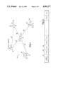
- FIG. 1 is a block diagram of a data communication network
- FIG. 2 is a format diagram of a scan
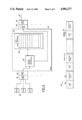
- FIG. 3 is a block diagram of a node
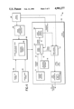
- FIG. 4 is a block diagram of an input/output processor of a node
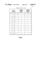
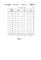
- FIG. 5 is a table of maximum timer intervals for various buffer utilizations
- FIG. 6 is a flow control table
- FIG. 7 is a format diagram of a set speed message.
- data communication network 10 include nodes 12, 14, 16, 18, 20 interconnected by data links 22, 24, 26, 28, 30. Each node serves one or more data terminals 32. Data flows from a first terminal to a second terminal over a preestablished virtual circuit data path that includes the nodes which serve the two terminals and some combination of intervening links and nodes necessary to complete a physical connection between the two terminals. For example, a path may be established from terminal 33 to terminal 35 via node 18, link 26, node 16, link 28, and node 20. Data paths are created or terminated from time to time according to need. Multiple data paths are multiplexed onto each physical data link.
- each link carries a succession of scans.
- Each scan is a series of 8-bit bytes arranged in fields including a scan initiator field 34 which uniquely marks the beginning of the scan.
- the remaining fields of the scan alternate between two types called deltas 36 and slots 38.
- Each scan potentially includes a slot 38 for each path currently established on that link. For example, slot 1 in successive scans together make up a particular path on the link and can carry a stream of data bytes.
- Each slot has a variable number of data bytes, so that the relative maximumaverage rates at which data bytes of different paths can be carried on the link is determined by the relative maximum numbers of data bytes (called slot weights) in the respective slots.
- the absolute rates at which data streams can be carried on a path also depend on the total length of each scan and the bit rate of the link.
- the speeds at which various paths can carry data can be changed by the upstream node reconfiguring the relative slot weights.
- the scan rate is no higher than a predetermined maximum rateand the scan rate changes as the slot weights change.
- Each slot has a maximum slot weight.
- the upstream terminal for the path may not be using the path at that time. If,when a scan is being assembled for transmission, an established path is notin use the slot corresponding to that path is omitted from the scan to savebandwidth. Each delta indicates how many, if any, slots have been omitted between two consecutive slots that are in the scan.
- a pool of 2000 FIFO data buffers 48 together make up a node buffer pool 49, which has a finite capacity.
- Data buffers 48 are allocated dynamically to the needs of the respective paths. If all of the buffers allocated to a given path are fullwhen another data byte arrives on that path, another buffer, if available, is allocated to that path.
- the addresses of the buffers presently allocated to a path are kept as a linked list.
- the flow of data bytes into node 42 via links from upstream nodes is regulated in the following way in order to effectively use the available capacity of buffers 48 without unnecessarily discarding data.
- IOP 46 contains a data buffer utilization monitor 58 which every two seconds looks at node buffer 49 and determines buffer utilization as the percentage of buffers 48 that are currently not empty. Based in part on this determination, a speed up/slow down evaluator 60 decides whether the individual paths should be examined and a number of them selected for which the incoming data rate from the upstream node should be slowed, or accelerated, or no action should be taken.
- a speed uptimer 62 and a slow down timer 64 respectively keep track of the amounts oftime which have elapsed since the last time consideration was given respectively to speeding up or slowing down the inbound data speed on any path.
- a maximum interval table 66 in evaluator 60 relates the percentage of buffers 48 currently being used (i.e., not empty) to the maximum elapsed times on timers 62, 64 before speeding up or slowing down should be considered.
- maximum interval table 66 contains, for each successive range of 10 percent in the buffer used percentage, the maximum intervals which may elapse on each of timers 62, 64 without analyzing paths to determine whether they should be sped up or slowed down, respectively. For example, given a buffer filled percentage of 35 percent,if the value of the speed up timer exceeds three seconds an analysis will be made of each path as to whether its inbound data rate, expressed in bytes per second, should be increased. If the values of both timers exceedthe intervals in their respective columns in table 66, both analyses are made for each path. The maximum interval for the speed up timer increases with higher buffer used percentages, and conversely for the slow down timer. Therefore, when the buffer is almost full, speeding up is considered relatively infrequently while slowing down is considered relatively frequently.
- a path analyzer 65 which considers individual paths for speeding up or slowing down as the case may be, based on the path s ideal speed and a flow control table 68.
- Path analyzer 65 includes an ideal speed calculator 70 that calculates an ideal speed 67 for each path based on the most recently specified (current) speed 72 specified for data leaving the node on an outbound leg of the path as found in current speed buffers 71, and the maximum outboundbandwidth 74 available to the path, derived from maximum bandwidth buffers 75.
- One of two formulas for the ideal speed is applied by calculator 70; the determination of which formula will be used is based on whether or not more than two seconds worth of outgoing data for that path is currently buffered.
- Ideal speed calculator 70 watches the utilization of each path'sbuffers 48. While the path's buffers hold less than two seconds worth of outgoing data at the unadjusted ideal speed, the ideal speed is updated tothe highest speed at which data can be transmitted to the down stream node,i.e., ideal speed equals the minimum of the previously set speed or the maximum bandwidth.
- calculator 70 calculates a speed ratio 76 which is the ratio of the updated ideal speed to the most recent inbound speed 72. If this ratio is less than 1.0, it indicates that data can be accepted from the upstream node at a higher rate; if the ratio is greater than 1.0, it indicates that data is arriving at too great a rate.
- flow control table 68 is a static table which, based on the speed ratio 76 and the buffers used percentage 77, specifies whether the path associated with a given speed ratio should be selected for speeding up or slowing down and, if it is selected, provides a change factor 80 by which the ideal speed for the given path is multiplied to arrive at the new incoming speed for that path.
- Two columns 100, 101 contain threshold ratio values for use respectively in making speed up or slow down decisions. The low threshold values 100 are used when selecting paths to slow down. If for a given buffers used percentage, the speed ratio 76 is less than the corresponding low threshold value 100, the path will be selected, otherwise it will not.
- the speed ratio must be increasingly smaller to trigger an incoming data flow reduction. For example, a speed ratio of 0.9 will causea path to be selected for slowing down if the buffers are 80% used. If, however, the buffers are only 8% used, the speed ratio must be less than 0.05 to trigger slowing down.
- the high threshold values 101 are applied when paths to be sped up are being selected. If a given speed ratio is higher than the high threshold level indicated for the current buffers used percentage the path will be selected. As the buffers used percentage increases, the speed ratio must be increasingly greater than 1.0 for the path to be selected.
- calculator 70 applies the speed ratio 76 to storage 68 which then passes to a new speed calculator 110 either the indicated change factor or a null value.
- Achange factor indicates that the path currently under evaluation has been selected for a speed change.
- a null value indicates that the path has not been selected. If a change factor is received, it is multiplied by ideal speed 67 to obtain a new speed 102.
- Data buffer utilization monitor 58 provides another value, the thirty second average 104, expressed in bytes per second, transmitted over the path.
- a non-zero average 104 indicates that the path is active.
- New speed calculator 110 examines average 104 and, if it is non-zero, selects that path by delivering a path identifier and a new speed value toa set speed assembler 120.
- a set speed assembler 120 To communicate the desired rates to the upstream node, a set speed assembler 120 assembles the desired rates into a special message called a set speed 122.
- a set speed 122 contains for each selected path a pathidentifier (path id) 124 and the new speed 102 for that path.
- path id path identifier
- Each set speed is broken into fields which alternate between two types; the path ids 124 occupy the first type of field and the new speeds 102 occupy the second.
- Set speeds are sent to the upstream node over a control path that is carried on the link.
- Each upstream node disassembles each received set speed 122, stores the newspeeds 102 in its current speed buffers 71, and reconfigures its outbound scans accordingly.
Abstract
Description
Claims (22)
Priority Applications (1)
| Application Number | Priority Date | Filing Date | Title |
|---|---|---|---|
| US07/144,756 US4901277A (en) | 1985-09-17 | 1988-01-19 | Network data flow control technique |
Applications Claiming Priority (2)
| Application Number | Priority Date | Filing Date | Title |
|---|---|---|---|
| US77707885A | 1985-09-17 | 1985-09-17 | |
| US07/144,756 US4901277A (en) | 1985-09-17 | 1988-01-19 | Network data flow control technique |
Related Parent Applications (1)
| Application Number | Title | Priority Date | Filing Date |
|---|---|---|---|
| US77707885A Continuation | 1985-09-17 | 1985-09-17 |
Publications (1)
| Publication Number | Publication Date |
|---|---|
| US4901277A true US4901277A (en) | 1990-02-13 |
Family
ID=26842331
Family Applications (1)
| Application Number | Title | Priority Date | Filing Date |
|---|---|---|---|
| US07/144,756 Expired - Lifetime US4901277A (en) | 1985-09-17 | 1988-01-19 | Network data flow control technique |
Country Status (1)
| Country | Link |
|---|---|
| US (1) | US4901277A (en) |
Cited By (25)
| Publication number | Priority date | Publication date | Assignee | Title |
|---|---|---|---|---|
| US5623644A (en) * | 1994-08-25 | 1997-04-22 | Intel Corporation | Point-to-point phase-tolerant communication |
| US5623607A (en) * | 1993-10-05 | 1997-04-22 | Hitachi, Ltd. | Data transfer control method for controlling transfer of data through a buffer without causing the buffer to become empty or overflow |
| US5724514A (en) * | 1994-11-25 | 1998-03-03 | Netmanage | System, method and apparatus for controlling the transfer of data objects over a communications link |
| US5737531A (en) * | 1995-06-27 | 1998-04-07 | International Business Machines Corporation | System for synchronizing by transmitting control packet to omit blocks from transmission, and transmitting second control packet when the timing difference exceeds second predetermined threshold |
| US5754754A (en) * | 1995-07-26 | 1998-05-19 | International Business Machines Corporation | Transmission order based selective repeat data transmission error recovery system and method |
| US5754789A (en) * | 1993-08-04 | 1998-05-19 | Sun Microsystems, Inc. | Apparatus and method for controlling point-to-point interconnect communications between nodes |
| US6018465A (en) * | 1996-12-31 | 2000-01-25 | Intel Corporation | Apparatus for mounting a chip package to a chassis of a computer |
| EP0976284A1 (en) * | 1996-07-12 | 2000-02-02 | Glenayre Electronics, Inc. | Method of congestion control for wireless messaging systems |
| US6065059A (en) * | 1996-12-10 | 2000-05-16 | International Business Machines Corporation | Filtered utilization of internet data transfers to reduce delay and increase user control |
| US6064805A (en) * | 1997-07-02 | 2000-05-16 | Unisys Corporation | Method, system, and computer program product for intraconnect data communication using buffer pools and buffer pool management |
| US6088729A (en) * | 1997-07-02 | 2000-07-11 | Unisys Corporation | Method, system, and computer program product for establishing dialogs in an intraconnect data communication |
| US6137688A (en) * | 1996-12-31 | 2000-10-24 | Intel Corporation | Apparatus for retrofit mounting a VLSI chip to a computer chassis for current supply |
| US6252851B1 (en) | 1997-03-27 | 2001-06-26 | Massachusetts Institute Of Technology | Method for regulating TCP flow over heterogeneous networks |
| US20010023438A1 (en) * | 2000-01-17 | 2001-09-20 | Hironobu Ishida | Method, apparatus, and recording medium for controlling image data transfer |
| US6345296B1 (en) * | 1997-07-02 | 2002-02-05 | Unisys Corporation | Method system and computer program product for providing pull model data communication |
| US6493335B1 (en) | 1996-09-24 | 2002-12-10 | At&T Corp. | Method and system for providing low-cost high-speed data services |
| US6778499B1 (en) * | 1999-06-18 | 2004-08-17 | Nortel Networks Limited | Method and apparatus for enabling the smooth transmission of bursty data in a wireless communications system |
| US20040198493A1 (en) * | 2001-03-22 | 2004-10-07 | Harold Mattice | Gaming system for individual control of access to many devices with few wires |
| US6839321B1 (en) | 2000-07-18 | 2005-01-04 | Alcatel | Domain based congestion management |
| US6937568B1 (en) * | 1999-11-15 | 2005-08-30 | Cisco Technology, Inc. | Adaptive rate shaping to prevent overflow |
| US20100180004A1 (en) * | 2009-01-12 | 2010-07-15 | Network Instruments, Llc | Apparatus and methods for network analysis |
| US7839876B1 (en) * | 2006-01-25 | 2010-11-23 | Marvell International Ltd. | Packet aggregation |
| US20150256444A1 (en) * | 1996-10-31 | 2015-09-10 | Patentmarks Communications, Llc | Multi-protocol telecommunications routing optimization |
| US9356793B1 (en) * | 2012-02-09 | 2016-05-31 | Google Inc. | System and method for managing load on a downstream server in a distributed storage system |
| EP3757781A4 (en) * | 2018-03-19 | 2021-03-24 | Huawei Technologies Co., Ltd. | Data processing method and system |
Citations (6)
| Publication number | Priority date | Publication date | Assignee | Title |
|---|---|---|---|---|
| US3200192A (en) * | 1962-01-15 | 1965-08-10 | Teletype Corp | Communication system |
| US3749845A (en) * | 1971-08-27 | 1973-07-31 | Bell Telephone Labor Inc | Digital data communication system |
| US4156798A (en) * | 1977-08-29 | 1979-05-29 | Doelz Melvin L | Small packet communication network |
| GB2022373A (en) * | 1978-04-28 | 1979-12-12 | Ericsson L M Pty Ltd | Interconnecting terminal devices in a digital data network |
| US4476527A (en) * | 1981-12-10 | 1984-10-09 | Data General Corporation | Synchronous data bus with automatically variable data rate |
| WO1985002963A1 (en) * | 1983-12-27 | 1985-07-04 | American Telephone & Telegraph Company | Communication system having reconfigurable data terminals |
-
1988
- 1988-01-19 US US07/144,756 patent/US4901277A/en not_active Expired - Lifetime
Patent Citations (6)
| Publication number | Priority date | Publication date | Assignee | Title |
|---|---|---|---|---|
| US3200192A (en) * | 1962-01-15 | 1965-08-10 | Teletype Corp | Communication system |
| US3749845A (en) * | 1971-08-27 | 1973-07-31 | Bell Telephone Labor Inc | Digital data communication system |
| US4156798A (en) * | 1977-08-29 | 1979-05-29 | Doelz Melvin L | Small packet communication network |
| GB2022373A (en) * | 1978-04-28 | 1979-12-12 | Ericsson L M Pty Ltd | Interconnecting terminal devices in a digital data network |
| US4476527A (en) * | 1981-12-10 | 1984-10-09 | Data General Corporation | Synchronous data bus with automatically variable data rate |
| WO1985002963A1 (en) * | 1983-12-27 | 1985-07-04 | American Telephone & Telegraph Company | Communication system having reconfigurable data terminals |
Non-Patent Citations (1)
| Title |
|---|
| CCITT Recommendation X.25. * |
Cited By (34)
| Publication number | Priority date | Publication date | Assignee | Title |
|---|---|---|---|---|
| US5754789A (en) * | 1993-08-04 | 1998-05-19 | Sun Microsystems, Inc. | Apparatus and method for controlling point-to-point interconnect communications between nodes |
| US6081844A (en) * | 1993-08-04 | 2000-06-27 | Sun Microsystems, Inc. | Point-to-point interconnect communications utility |
| US5623607A (en) * | 1993-10-05 | 1997-04-22 | Hitachi, Ltd. | Data transfer control method for controlling transfer of data through a buffer without causing the buffer to become empty or overflow |
| US5623644A (en) * | 1994-08-25 | 1997-04-22 | Intel Corporation | Point-to-point phase-tolerant communication |
| US5724514A (en) * | 1994-11-25 | 1998-03-03 | Netmanage | System, method and apparatus for controlling the transfer of data objects over a communications link |
| US5737531A (en) * | 1995-06-27 | 1998-04-07 | International Business Machines Corporation | System for synchronizing by transmitting control packet to omit blocks from transmission, and transmitting second control packet when the timing difference exceeds second predetermined threshold |
| US5754754A (en) * | 1995-07-26 | 1998-05-19 | International Business Machines Corporation | Transmission order based selective repeat data transmission error recovery system and method |
| EP0976284A4 (en) * | 1996-07-12 | 2001-08-16 | Glenayre Electronics Inc | Method of congestion control for wireless messaging systems |
| EP0976284A1 (en) * | 1996-07-12 | 2000-02-02 | Glenayre Electronics, Inc. | Method of congestion control for wireless messaging systems |
| US6493335B1 (en) | 1996-09-24 | 2002-12-10 | At&T Corp. | Method and system for providing low-cost high-speed data services |
| US9806988B2 (en) * | 1996-10-31 | 2017-10-31 | Patentmarks Communications, Llc | Multi-protocol telecommunications routing optimization |
| US20150256444A1 (en) * | 1996-10-31 | 2015-09-10 | Patentmarks Communications, Llc | Multi-protocol telecommunications routing optimization |
| US6065059A (en) * | 1996-12-10 | 2000-05-16 | International Business Machines Corporation | Filtered utilization of internet data transfers to reduce delay and increase user control |
| US6137688A (en) * | 1996-12-31 | 2000-10-24 | Intel Corporation | Apparatus for retrofit mounting a VLSI chip to a computer chassis for current supply |
| US6462943B1 (en) | 1996-12-31 | 2002-10-08 | Intel Corporation | Method and apparatus for retrofit mounting a VLSI chip to a computer chassis for current supply |
| US6018465A (en) * | 1996-12-31 | 2000-01-25 | Intel Corporation | Apparatus for mounting a chip package to a chassis of a computer |
| US6252851B1 (en) | 1997-03-27 | 2001-06-26 | Massachusetts Institute Of Technology | Method for regulating TCP flow over heterogeneous networks |
| US6345296B1 (en) * | 1997-07-02 | 2002-02-05 | Unisys Corporation | Method system and computer program product for providing pull model data communication |
| US6064805A (en) * | 1997-07-02 | 2000-05-16 | Unisys Corporation | Method, system, and computer program product for intraconnect data communication using buffer pools and buffer pool management |
| US6088729A (en) * | 1997-07-02 | 2000-07-11 | Unisys Corporation | Method, system, and computer program product for establishing dialogs in an intraconnect data communication |
| US6778499B1 (en) * | 1999-06-18 | 2004-08-17 | Nortel Networks Limited | Method and apparatus for enabling the smooth transmission of bursty data in a wireless communications system |
| US6937568B1 (en) * | 1999-11-15 | 2005-08-30 | Cisco Technology, Inc. | Adaptive rate shaping to prevent overflow |
| US20010023438A1 (en) * | 2000-01-17 | 2001-09-20 | Hironobu Ishida | Method, apparatus, and recording medium for controlling image data transfer |
| US6839321B1 (en) | 2000-07-18 | 2005-01-04 | Alcatel | Domain based congestion management |
| US20040198493A1 (en) * | 2001-03-22 | 2004-10-07 | Harold Mattice | Gaming system for individual control of access to many devices with few wires |
| US7462103B2 (en) * | 2001-03-22 | 2008-12-09 | Igt | Gaming system for individual control of access to many devices with few wires |
| US9225658B1 (en) | 2006-01-25 | 2015-12-29 | Marvell International Ltd. | Packet aggregation |
| US7839876B1 (en) * | 2006-01-25 | 2010-11-23 | Marvell International Ltd. | Packet aggregation |
| US8498305B1 (en) | 2006-01-25 | 2013-07-30 | Marvell International Ltd. | Packet aggregation |
| US8204958B2 (en) * | 2009-01-12 | 2012-06-19 | Network Instruments, Llc | Apparatus and methods for network analysis |
| US20100180004A1 (en) * | 2009-01-12 | 2010-07-15 | Network Instruments, Llc | Apparatus and methods for network analysis |
| US9356793B1 (en) * | 2012-02-09 | 2016-05-31 | Google Inc. | System and method for managing load on a downstream server in a distributed storage system |
| US10009250B2 (en) | 2012-02-09 | 2018-06-26 | Google Llc | System and method for managing load in a distributed storage system |
| EP3757781A4 (en) * | 2018-03-19 | 2021-03-24 | Huawei Technologies Co., Ltd. | Data processing method and system |
Similar Documents
| Publication | Publication Date | Title |
|---|---|---|
| US4901277A (en) | Network data flow control technique | |
| EP0577359B1 (en) | Congestion control in high speed networks | |
| US7423972B2 (en) | System and method for a transmission rate controller | |
| EP0166765B1 (en) | Arrangement for routing data packets through a circuit switch | |
| EP0732019B1 (en) | Control of overload situations in frame relay network | |
| US5822540A (en) | Method and apparatus for discarding frames in a communications device | |
| CA2130403C (en) | Atm switching system and cell control method | |
| KR100234212B1 (en) | The congestion control based on adaptive speed control in packet network | |
| EP0464024B1 (en) | Congestion free packet network | |
| US5970048A (en) | Control of overload situations in frame relay network | |
| US6615271B1 (en) | Traffic control system having distributed rate calculation and link flow control | |
| JP2693266B2 (en) | Data cell congestion control method in communication network | |
| EP1508227B1 (en) | Buffer memory reservation | |
| US6539026B1 (en) | Apparatus and method for delay management in a data communications network | |
| EP0587522A2 (en) | Rate-based congestion control in packet communications networks | |
| EP0719012A2 (en) | Traffic management and congestion control for packet-based network | |
| US7839787B2 (en) | Delay-based overflow routing in communication systems | |
| US6452901B1 (en) | Cell loss balance system and method for digital network | |
| US5629936A (en) | Control of consecutive packet loss in a packet buffer | |
| US6996119B2 (en) | Adaptive polling method for router | |
| GB2181926A (en) | Network data flow control | |
| US6785235B1 (en) | Priority control of queued data frames in frame delay multiplexing | |
| KR100745679B1 (en) | Method and apparatus for packet scheduling using adaptation round robin | |
| US7039011B1 (en) | Method and apparatus for flow control in a packet switch | |
| US7142558B1 (en) | Dynamic queuing control for variable throughput communication channels |
Legal Events
| Date | Code | Title | Description |
|---|---|---|---|
| STCF | Information on status: patent grant |
Free format text: PATENTED CASE |
|
| AS | Assignment |
Owner name: K-SWISS INC., A CORP. OF DE, DELAWARE Free format text: RELEASED BY SECURED PARTY;ASSIGNOR:NATIONAL CANADA FUNERAL CORP., A CORP. OF DE;REEL/FRAME:005594/0395 Effective date: 19910115 Owner name: SECURITY PACIFIC NATIONAL BANK,, CALIFORNIA Free format text: SECURITY INTEREST;ASSIGNOR:K-SWISS INC.;REEL/FRAME:005594/0410 Effective date: 19910115 |
|
| FEPP | Fee payment procedure |
Free format text: PAYOR NUMBER ASSIGNED (ORIGINAL EVENT CODE: ASPN); ENTITY STATUS OF PATENT OWNER: LARGE ENTITY |
|
| FPAY | Fee payment |
Year of fee payment: 4 |
|
| AS | Assignment |
Owner name: BANK OF AMERICA NATIONAL TRUST AND SAVINGS ASSOCIA Free format text: RELEASE BY SECURED PARTY;ASSIGNOR:K-SWISS, INC.;REEL/FRAME:007108/0714 Effective date: 19940325 |
|
| AS | Assignment |
Owner name: MOTOROLA, INC., ILLINOIS Free format text: MERGER (EFFECTIVE 12-31-94).;ASSIGNOR:CODEX CORPORATION;REEL/FRAME:007268/0432 Effective date: 19941216 |
|
| FPAY | Fee payment |
Year of fee payment: 8 |
|
| FPAY | Fee payment |
Year of fee payment: 12 |