US4901726A - Rate-responsive, distributed-rate pacemaker - Google Patents
Rate-responsive, distributed-rate pacemaker Download PDFInfo
- Publication number
- US4901726A US4901726A US07/355,275 US35527589A US4901726A US 4901726 A US4901726 A US 4901726A US 35527589 A US35527589 A US 35527589A US 4901726 A US4901726 A US 4901726A
- Authority
- US
- United States
- Prior art keywords
- parameter
- rate
- rcp
- time
- values
- Prior art date
- Legal status (The legal status is an assumption and is not a legal conclusion. Google has not performed a legal analysis and makes no representation as to the accuracy of the status listed.)
- Expired - Lifetime
Links
Images

Classifications
-
- A—HUMAN NECESSITIES
- A61—MEDICAL OR VETERINARY SCIENCE; HYGIENE
- A61N—ELECTROTHERAPY; MAGNETOTHERAPY; RADIATION THERAPY; ULTRASOUND THERAPY
- A61N1/00—Electrotherapy; Circuits therefor
- A61N1/18—Applying electric currents by contact electrodes
- A61N1/32—Applying electric currents by contact electrodes alternating or intermittent currents
- A61N1/36—Applying electric currents by contact electrodes alternating or intermittent currents for stimulation
- A61N1/362—Heart stimulators
- A61N1/365—Heart stimulators controlled by a physiological parameter, e.g. heart potential
Definitions
- This invention relates to rate-responsive pacemakers, and more particularly to a rate-responsive pacemaker which exhibits a predetermined rate distribution independent of the distribution of the rate-control parameter.
- a rate-responsive pacemaker is one which adjusts its rate in accordance with the value of a measured parameter. Because the value of the parameter is used to control the rate, it is generally referred to as a rate-control parameter (RCP).
- RCP rate-control parameter
- the RCP varies with the physiological needs of the body and is dependent upon such factors as stress, and whether the patient is exercising or at rest.
- Illustrative rate-control parameters include respiratory minute volume, QT interval, temperature and physical vibration.
- a rate-responsive pacemaker generally exhibits some characteristic which expresses the desired rate as a function of the RCP. Where the rate control is based upon such a built-in characteristic, there are necessarily several disadvantages.
- the RCP value for any given state of stress or exercise does not remain constant for the life of the pacemaker.
- the RCP is measured by a sensor attached to a pacemaker lead, or it is derived from the sensed electrogram signal. In either case, if the lead changes position, all values of the RCP may be shifted. If there is no way to account for shifts of this kind, it is possible for all pacing rates to be shifted downwardly or upwardly.
- the invention has more general applicability in that it can be used in any automatic gain control system for relating a controlled parameter to a controlling parameter.
- the pacemaker is not programmed to pace at a particular rate for a particular value of the RCP. Instead, there is stored a function which represents the desired rate distribution. Using discrete values, the function might call for a rate of 70 beats per minute (bpm) to be the operative rate 40% of the time, a rate of 80 bpm to be the operative rate for 10% of the time, etc.
- the pacemaker also generates a probability distribution function of recent RCP values. For example, it may be determined that over the last month or so 25% of the time the RCP had a value of 5, 20% of the time it had a value of 6, etc. From these two functions, two percentile rankings are developed. Each percentile ranking is a cumulative distribution function.
- the function for the desired rate distribution might represent that the rate should be less than 60 bpm 10% of the time, less than 65 bpm 30% of the time, less than 70 bpm 70% of the time, etc.
- the percentile ranking for the recent RCP values takes a similar form. For example, the RCP values over the last month may have been less than 3 15% of the time, less than 4 35% of the time, less than 5 60% of the time, etc.
- the two percentile rankings are then used to determine the pacing rate at any instant.
- the instantaneous RCP is measured and its percentile ranking is determined from the percentile ranking table of recent RCP values. Using that percentile, the percentile ranking table for rates is consulted. The rate corresponding to the previously determined percentile is the one used by the pacemaker.
- the net result is that the rates at which the pacemaker paces have a probability distribution which corresponds to the desired (programmed) rate distribution.
- the pacemaker is self-adapting, provided that there is maintained a probability distribution function for recent RCP values. As the RCP values change with the administration of drugs and other long-term effects, the rate distribution is automatically mapped onto the RCP value distribution.
- FIG. 1 depicts the general prior art approach by which the rate of a rate-responsive pacemaker is determined from the value of an RCP;
- FIG. 2 represents two examples of a rate distribution which may be desired by a physician
- FIG. 3 depicts a typical probability function for measured RCP values
- FIGS. 4A and 4B depict a typical RCP probability distribution function (histogram) and corresponding percentile ranking in the illustrative embodiment of the invention
- FIGS. 5A and 5B depict a typical desired rate probability distribution function and percentile ranking in the illustrative embodiment of the invention
- FIG. 6 depicts the percentile rankings of FIGS. 4B and 5B in table form, and further illustrates the steps involved in going from a measured RCP value to the setting of the pacing rate;
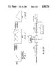
- FIG. 7 is a block diagram of a pacemaker which implements the method of my invention.
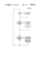
- FIG. 8 is a flow chart of the master processing loop of the pacemaker of FIG. 7.
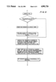
- FIG. 9 is a flow chart of the steps executed in the "Sample RCP and Update" block of FIG. 8.
- the curve of FIG. 1 is the kind of function which characterizes a typical prior art rate-responsive pacemaker. For every value of the rate-control parameter, there is a corresponding pacing rate.
- the characteristic may be non-linear not only because the sensor itself may be a non-linear device, but also because it may be desired that the pacing rate vary with RCP in a non-linear fashion.
- the basic problem with providing a pacemaker with a built-in function of the type represented by FIG. 1 is that the function must change with time if the same level of stress is always to result in the same pacing rate. This is because RCP values typically vary with the administration of drugs, changes in sensor sensitivity over time, etc.
- the basis for the present invention is that there is a desired probability distribution of pacing rates, of the type depicted in FIG. 2.
- a physician might desire that curve A characterize the pacer operation. What the curve represents is the probability of occurrence of every pacing rate.
- the probability function is comparable to the probability distribution function of FIG. 5A, the latter representing a distribution in terms of discrete rates. Referring to FIG. 5A, it is assumed that the physician desires that there be only seven possible rates, ranging from 60 to 90 bpm, in 5-bpm increments.
- the desired rate distribution is such that a rate of 60 bpm will apply 10% of the time, a rate of 65 bpm will apply 20% of the time, etc.
- Curve A might apply to an inactive patient, while curve B might apply to an active patient; in the latter case, the rate curve is skewed toward a higher range.
- One such probability distribution function is shown in FIG. 5A. Whichever function is programmed, that is the function which the physician desires to apply to the patient for the life of the pacemaker, or at least until it is re-programmed.
- the probability distribution function in no way correlates rates and RCP values. All that is known from the probability distribution function is that if a continuous record is kept of how often the pacer operated at each of the possible rates, it will be found that each rate was in effect for a percentage of the total time which corresponds to that shown in FIG. 5A. How the desired distribution is achieved based upon measured values of RCP is what the invention is all about.
- FIG. 2 depicts the desired probability of rate
- the curve of FIG. 3 depicts the probability of RCP values as actually measured. For each value of RCP, there is a certain probability that it will be measured.
- the curve of FIG. 3 is not fixed as is the desired rate probability occurring depends upon long-term changes, drug therapies, changes in sensor sensitivity, changes in patient lifestyle, etc.
- a curve such as that shown in FIG. 3 represents the actual measurements of RCP
- curve A or curve B of FIG. 2 represents a permanent desired rate distribution.
- FIG. 4A represents a probability distribution function of recent RCP values.
- running counts are maintained of measured RCP values. Only discrete values of RCP are considered; thus an RCP value such as 4.7 would be treated as a value of 5.
- the probability distribution function values are shown in FIG. 4A in normalized fashion, that is, each value is a percentage with the total adding up to 100%. What this means, for example, is that of all possible RCP values over the last month or so, a value of 5 was measured 25% of the time, a value of 6 was measured 20% of the time, etc.
- FIGS. 4A and 5A are comparable in that they are both normalized so that the individual probabilities in each case add up to 100%.
- the first step in relating RCP values to rate is to recast the probability distribution functions of FIGS. 4A and 5A into percentile rankings of RCP values and rates, as shown in FIGS. 4B and 5B.
- a percentile ranking is the same as a cumulative distribution function (CDF).
- CDF cumulative distribution function
- the percentile ranking of the highest possible RCP is necessarily 100 because all measured RCP values are less than or equal to 8.
- a percentile ranking is necessarily a monotonically increasing function.
- the percentile ranking of the desired rates can be derived from the corresponding probability distribution function, although the percentile ranking can actually be programmed in the pacer without having to go through the mathematical manipulation starting with a probability distribution function of rates. Referring to FIGS. 5A and 5B, for example, rates of 75 bpm or less occur 80% of the time (as shown in FIG. 5B), and this value is derived by adding together the four individual probabilities (10%, 20%, 40% and 10%) for the four rates which are equal to 75 bpm or less in FIG. 5A.
- the rate which is set in the pacemaker is derived in the following way, with reference to a particular example. In the following discussion, the steps of the method are shown by the circled digits 1-5.
- the first step involves measuring the instantaneous value of the RCP, something which is done in every rate-responsive pacemaker.
- the particular RCP is of no moment insofar as the subject invention is concerned, although the assignee of this application markets a rate-responsive pacemaker in which the RCP is respiratory minute volume.
- It is assumed in the example that the measured value of RCP is 5.
- all RCP values are to the nearest integer, and all rate values are to the nearest multiple of 5 bpm.
- the RCP percentile ranking table is consulted and in step 2 it is determined that the pacemaker has been operating over the last month or so such that values of RCP of 5 or less have been measured 60% of the time.
- this percentile value of 60 is used as an entry into the rate percentile ranking table. There is no percentile value of 60 since the values derived from FIG. 5B in the illustrated example have a table entry of 70 following a table entry of 30. The next highest table entry is selected, 70 in this case. It is known from the rate percentile ranking table that a rate equal to or less than 70 bpm is desired 70% of the time. In the last step, the pacer is set to operate at a rate of 70 bpm.
- step 3 it is in step 3 that the correspondence is established between the RCP percentile ranking and the desired rate percentile ranking. It is not possible to relate to selves.
- RCP values of 4 and 6 both occur 20% of the time.
- a rate of 65 is desired by the physician to apply 20% of the time. Since any rate versus RCP curve such as that shown in FIG. 1 is generally monotonically increasing as shown, or decreasing, it would not be possible to relate only one of the RCP values of 4 and 6 to the 65-bpm rate. This is not to say that with monotonically increasing or decreasing functions several values of RCP will not map onto the same rate. For example, referring to FIG.
- FIG. 5A it will be seen that rates of 65 and 70 bpm are desired a total of 60% of the time. It is therefore to be expected that multiple values of RCP will map onto the 65-70 bpm region of the rate percentile table. If the probability distribution function of desired rate involves smaller discrete steps, then there will be fewer "big jumps". It is apparent, for example, that because a rate of 70 bpm is to occur 40% of the time, there necessarily has to be a 40% jump in the rate percentile ranking table as shown in FIG. 6. Obviously the jumps would be much smaller if rates of 67, 69, 71 and 73 were each to occur 10% of the time.
- step 3 of FIG. 6 An entry is made to the percentile ranking of 70 rather than a percentile ranking of 30. It is not because the value of 60 taken from the RCP percentile ranking table is closer to 70 than to 30. Were the RCP value measured equal to 4 and a percentile ranking of 35 derived from the left table of FIG. 6 in step 2, the entry to the rate percentile ranking table would still be to the 70 line rather than the 30 line, even though 35 is closer to 30 than to 70. The reason has to do with the mapping rationale. In the example shown in FIG. 6, an RCP value exists such that this value and lesser values have been obtained 60% of the time over some relatively long interval. What is therefore desired is a rate such that that rate and slower rates similarly are desired 60% of the time.
- rate percentile ranking table of FIG. 6 entered at the 30 level, for which a rate of 65 bpm would be set, what it would mean is that a rate was selected such that that rate and lower values are desired 30% of the time. That does not correspond to RCP values which have been measured 60% of the time. But an entry to the rate percentile ranking table at the 70 line means that the rate which will be set and all lower rates are desired 70% of the time. This necessarily means that they are desired at least 60% of the time, and this corresponds to the range of RCP values (3-5) which have been measured 60% of the time.
- the percentile ranking is 15.
- the rate percentile ranking table is entered between the 10 and 30 percentiles, and this means that the 30 line is selected, i.e., the lowest rate which can be set is 65 bpm even though the physician included a 60-bpm rate in his rate distribution. With finer quantization, however, it is likely that such a situation will not arise.
- RCP values of 3 or less will be represented less than 15% of the time. For example, suppose that they exist only 8% of the time. In such a case, the first entry in the RCP percentile ranking table will be less than 8, and for any value of RCP of 3 or less a rate of 60 bpm will be selected from the rate percentile ranking table.
- FIG. 7 depicts the manner in which a pacemaker can be constructed to implement the subject invention.
- a sensor input is applied over line 8 to RCP sampler 10.
- the sensor input may be a chemical measurement, an electrical parameter or even the signal picked up by a pacemaker electrode (shown by the numeral 35).
- the RCP sampler 10 simply delivers periodic samples of the RCP to microprocessor 15.
- the microprocessor cooperates with memory 20 to derive its operating instructions and for storing data.
- the microprocessor senses cardiac potentials amplified by amplifier 30, and similarly causes pulse generator 25 to generate a pacing stimulus when it is needed.
- the illustrative embodiment of the invention is a VVI pacer; it can be standard in all respects except that its escape interval is adjusted in accordance with the current value of the RCP.
- the master processing loop flow chart is shown in FIG. 8. At the top, a test for heartbeat sensing is shown. If a heartbeat is sensed, the pace timer is reset so that a new escape interval can be timed. However, if a heartbeat is not sensed, a check is made whether the time which has elapsed since the last resetting of the timer is greater than the escape interval. If it is, it is an indication that a stimulus is required, and two steps now take place. First, the pace timer is reset so that another cycle of operation can begin. Second, the patient is paced by causing pulse generator 25 on FIG. 7 to operate.
- RCP samples are taken every five seconds. As long as five seconds have not elapsed since the last sample was taken, the system simply moves on to the sense step at the top of the flow chart. But if five seconds have gone by, the first thing that is done is to reset the RCP sample timer in preparation for another cycle. An RCP sample is then taken and various updating operations take place.
- the box labeled "sample RCP and update" on the flow chart of FIG. 8 is shown in detail in FIG. 9; it is in the flow chart of FIG. 9 that the various steps described with reference to FIGS. 4-6 are carried out.
- the percentile ranking of FIG. 4B is updated approximately six times per day.
- the timer is not exactly four hours because that would mean that six samples would be taken every day, at the same six times every day.
- the sample values which are stored are more representative of all RCP values, with each time of day being given equal importance.
- the RCP percentile update timer is reset so that another sample will be used to update the ranking 3.7 hours from now. Then the oldest RCP sample in a 200-location memory is replaced with the current sample. The system stores the most recent 200 samples. If approximately six samples are taken each day, the samples stored represent the RCP values measured during the last month of pacer operation.
- the new percentile ranking is computed. How this is done is described in the next step on FIG. 9.
- the probability distribution function of FIG. 4A need not actually be derived, and instead the percentile ranking of FIG. 4B can be derived directly from the 200 stored samples, it is convenient to consider the processing in two steps.
- a count is taken of the samples which correspond to each discrete value of RCP for which a count is maintained; the total is divided by two to derive the probability distribution function value for that particular RCP.
- the percentile ranking of FIG. 48 for each value of RCP is then computed simply by adding together the probability of that value of RCP and the probabilities of all RCPs of lesser value. In effect, the percentile ranking which is derived represents the history of RCP measurements over the last month or so.
- the next step in FIG. 9 describes what is shown in FIG. 6 of the drawing. It should be appreciated that although RCP samples are used to update the percentile ranking only approximately once every four hours, an RCP sample is taken every five seconds, as shown in FIG. 8, and every five seconds the pacing rate is adjusted in accordance with the steps shown in FIG. 6.
- the last step in the flow chart of FIG. 9 simply entails setting the escape interval so that it is equal to the reciprocal of the new rate; as is known in the art, the escape interval is simply the reciprocal of the rate.
- the first relates to the concern which has existed since the early days of pacemakers about the generation of pacing pulses at rates which are excessively high. While a pacemaker usually includes a rate limiting circuit so that a maximum rate cannot be exceeded, that does not necessarily prevent sustained pacing at the maximum rate. In the invention, however, no matter how "wild" the RCP values become, high pacing rates cannot be sustained. In effect there is a form of negative feedback; the pacer self-adapts to the RCP value distribution, even if all of the values are unusually high.
- Another advantage relates to the fact that if a typical prior art rate-responsive pacemaker is not set up properly for a particular patient, the rate-responsive capability of the device will generally be useless. In the invention, however, not only is improper set-up of little concern, but there may be no need for set-up at all. Whatever the RCP values happen to be, and even if they are way too high or way too low because of improper set-up, the RCP percentile ranking is automatically mapped onto the percentile ranking of the desired rate distribution.
- the set-up procedure described in the above-identified Nappholz et al application requires measurements to be taken of the RCP while the patient is at rest and, after an interval of about an hour, when he suddenly starts to exercise strenuously.
- the RCP values are telemetered from the pacer and used by the programmer to program the pacer. In the invention there is no need for all of this, as the pacer self-adapts to long-term changes in RCP measurements which do not relate to instantaneous physiological needs.
- Another advantage pertains to the fact that prior art rate-responsive pacemakers pace at the nominal rate most of the time, with the rate going up when the patient is subject to stress or when he exercises. But there is often no difference in rate when the patient is sitting in a chair and when he is sleeping. If the set-up procedure involves a measurement of the RCP which corresponds to the minimum rate when the patient is at rest, there is generally no way to decrease the rate when the patient is sleeping. To do that would require that the minimum rate be set so that it corresponds to a still lower value of RCP which might be measured while the patient is asleep.
- a most significant advantage of the invention is that it is applicable to any rate control parameter. There is no need for different kinds of processing depending on the particular RCP which is used. The entire product line of a manufacturer may provide the same kind of operation, whether the individual pacemakers use rate control parameters involving temperature, minute volume, stroke volume, etc.
- the RCP values are completely arbitrary in the sense that there is no predesigned correspondence between them and the desired rates.
- the RCP can even be a non-linear parameter without affecting the self-adaptation (as long as changes in the RCP are monotonic). Even if the sensor is not working properly, whatever values of RCP actually exist have their percentile ranking automatically mapped onto the percentile ranking of the desired rate distribution. This is a remarkable result.
- the rate-responsive pacemaker of the invention exhibits a predetermined rate distribution, regardless of the distribution of the rate-control parameter values. This does not mean that the pacemaker ignores the parameter.
- the invention is a method of transforming an arbitrarily distributed parameter into a rate with a predetermined distribution. Two properties characterize the pacer of the invention. First, it is guaranteed to exhibit a programmed rate distribution. Second, the pacing rate is guaranteed to change monotonically with the measured RCP value so that as the RCP changes in any given direction, the pacing rate always changes in a corresponding direction.
Abstract
Description
Claims (6)
Priority Applications (1)
| Application Number | Priority Date | Filing Date | Title |
|---|---|---|---|
| US07/355,275 US4901726A (en) | 1988-01-29 | 1989-05-22 | Rate-responsive, distributed-rate pacemaker |
Applications Claiming Priority (2)
| Application Number | Priority Date | Filing Date | Title |
|---|---|---|---|
| US07/150,037 US4856522A (en) | 1988-01-29 | 1988-01-29 | Rate-responsive, distributed-rate pacemaker |
| US07/355,275 US4901726A (en) | 1988-01-29 | 1989-05-22 | Rate-responsive, distributed-rate pacemaker |
Related Parent Applications (1)
| Application Number | Title | Priority Date | Filing Date |
|---|---|---|---|
| US07/150,037 Division US4856522A (en) | 1988-01-29 | 1988-01-29 | Rate-responsive, distributed-rate pacemaker |
Publications (1)
| Publication Number | Publication Date |
|---|---|
| US4901726A true US4901726A (en) | 1990-02-20 |
Family
ID=26847271
Family Applications (1)
| Application Number | Title | Priority Date | Filing Date |
|---|---|---|---|
| US07/355,275 Expired - Lifetime US4901726A (en) | 1988-01-29 | 1989-05-22 | Rate-responsive, distributed-rate pacemaker |
Country Status (1)
| Country | Link |
|---|---|
| US (1) | US4901726A (en) |
Cited By (7)
| Publication number | Priority date | Publication date | Assignee | Title |
|---|---|---|---|---|
| US5154170A (en) * | 1990-08-14 | 1992-10-13 | Medtronic, Inc. | Optimization for rate responsive cardiac pacemaker |
| US5226413A (en) * | 1990-08-14 | 1993-07-13 | Medtronic, Inc. | Rate responsive pacemaker and method for automatically initializing the same |
| US5312453A (en) * | 1992-05-11 | 1994-05-17 | Medtronic, Inc. | Rate responsive cardiac pacemaker and method for work-modulating pacing rate deceleration |
| US5480441A (en) * | 1994-03-30 | 1996-01-02 | Medtronic, Inc. | Rate-responsive heart pacemaker |
| WO2001024875A1 (en) * | 1999-10-06 | 2001-04-12 | Cardiac Pacemakers, Inc. | Automatic rate-adaptive pacing with auto-lifestyle |
| US6408208B1 (en) | 1999-10-28 | 2002-06-18 | Cardiac Pacemakers, Inc. | Fully automatic and physiologic rate-adaptive pacing |
| US20040243192A1 (en) * | 2003-06-02 | 2004-12-02 | Hepp Dennis G. | Physiologic stimulator tuning apparatus and method |
Citations (5)
| Publication number | Priority date | Publication date | Assignee | Title |
|---|---|---|---|---|
| US2889991A (en) * | 1956-08-14 | 1959-06-09 | Follansbee Rogers | Heating system |
| US3940692A (en) * | 1972-12-15 | 1976-02-24 | The University Of Edinburgh | Apparatus for monitoring recurrent waveforms |
| US4403184A (en) * | 1978-04-28 | 1983-09-06 | Hewlett-Packard Company | Autocorrelation apparatus and method for approximating the occurrence of a generally periodic but unknown signal |
| US4796620A (en) * | 1986-05-13 | 1989-01-10 | Mieczyslaw Mirowski | System for sensing abnormal heart activity by means of heart rate acceleration and deceleration detection |
| US4813417A (en) * | 1987-03-13 | 1989-03-21 | Minnesota Mining And Manufacturing Company | Signal processor for and an auditory prosthesis utilizing channel dominance |
-
1989
- 1989-05-22 US US07/355,275 patent/US4901726A/en not_active Expired - Lifetime
Patent Citations (5)
| Publication number | Priority date | Publication date | Assignee | Title |
|---|---|---|---|---|
| US2889991A (en) * | 1956-08-14 | 1959-06-09 | Follansbee Rogers | Heating system |
| US3940692A (en) * | 1972-12-15 | 1976-02-24 | The University Of Edinburgh | Apparatus for monitoring recurrent waveforms |
| US4403184A (en) * | 1978-04-28 | 1983-09-06 | Hewlett-Packard Company | Autocorrelation apparatus and method for approximating the occurrence of a generally periodic but unknown signal |
| US4796620A (en) * | 1986-05-13 | 1989-01-10 | Mieczyslaw Mirowski | System for sensing abnormal heart activity by means of heart rate acceleration and deceleration detection |
| US4813417A (en) * | 1987-03-13 | 1989-03-21 | Minnesota Mining And Manufacturing Company | Signal processor for and an auditory prosthesis utilizing channel dominance |
Cited By (9)
| Publication number | Priority date | Publication date | Assignee | Title |
|---|---|---|---|---|
| US5154170A (en) * | 1990-08-14 | 1992-10-13 | Medtronic, Inc. | Optimization for rate responsive cardiac pacemaker |
| US5226413A (en) * | 1990-08-14 | 1993-07-13 | Medtronic, Inc. | Rate responsive pacemaker and method for automatically initializing the same |
| US5312453A (en) * | 1992-05-11 | 1994-05-17 | Medtronic, Inc. | Rate responsive cardiac pacemaker and method for work-modulating pacing rate deceleration |
| US5480441A (en) * | 1994-03-30 | 1996-01-02 | Medtronic, Inc. | Rate-responsive heart pacemaker |
| WO2001024875A1 (en) * | 1999-10-06 | 2001-04-12 | Cardiac Pacemakers, Inc. | Automatic rate-adaptive pacing with auto-lifestyle |
| US6490485B1 (en) | 1999-10-06 | 2002-12-03 | Cardiac Pacemakers, Inc. | Automatic rate-adaptive pacing with auto-lifestyle |
| US6408208B1 (en) | 1999-10-28 | 2002-06-18 | Cardiac Pacemakers, Inc. | Fully automatic and physiologic rate-adaptive pacing |
| US20040243192A1 (en) * | 2003-06-02 | 2004-12-02 | Hepp Dennis G. | Physiologic stimulator tuning apparatus and method |
| EP1484083A1 (en) * | 2003-06-02 | 2004-12-08 | CardioDynamics International Corporation | Physiologic stimulator tuning apparatus and method |
Similar Documents
| Publication | Publication Date | Title |
|---|---|---|
| US4856522A (en) | Rate-responsive, distributed-rate pacemaker | |
| AU650591B2 (en) | Work-modulated pacing rate deceleration | |
| US6823214B1 (en) | Self-calibrating rate-adaptive pacemaker | |
| US5514162A (en) | System and method for automatically determining the slope of a transfer function for a rate-responsive cardiac pacemaker | |
| US7493163B2 (en) | Rate-adaptive therapy with sensor cross-checking | |
| AU633236B2 (en) | Rate-responsive pacemaker with circuitry for processing multiple sensor inputs | |
| US4972834A (en) | Pacemaker with improved dynamic rate responsiveness | |
| US5622428A (en) | Method and apparatus for determination of a criterion of activity of a rate modulation parameter sensor in an active implantable medical device | |
| US5303702A (en) | Automatic adjustment of the control function for a rate adaptive pacemaker | |
| AU596337B2 (en) | Temperature responsive controller for cardiac pacer | |
| US5040534A (en) | Microprocessor controlled rate-responsive pacemaker having automatic rate response threshold adjustment | |
| CA2029998A1 (en) | Temperature-based rate-modulated cardiac therapy apparatus and method | |
| US6839593B1 (en) | Rate-adaptive therapy with automatic limiting of maximum pacing rate | |
| JP2005523784A (en) | Method and apparatus for rate response adjustment in an implantable medical device | |
| EP0625920A1 (en) | Providing an optimized pacing rate which varies with a patient's physiologic demand. | |
| JPH03503502A (en) | Microprocessor-controlled rate-responsive pacemaker with self-adjusting rate-response thresholds | |
| US4901726A (en) | Rate-responsive, distributed-rate pacemaker | |
| US5143065A (en) | Implantable device with circadian rhythm adjustment | |
| US5134997A (en) | Rate responsive pacemaker and pacing method | |
| EP1051992B1 (en) | Rate responsive pacemaker with improved rate change dynamics | |
| US5792196A (en) | Rate-responsive pacemaker with automatic rate response factor selection | |
| US5271396A (en) | Activity controlled pacer with automatic sensor response amplification adjustment |
Legal Events
| Date | Code | Title | Description |
|---|---|---|---|
| STCF | Information on status: patent grant |
Free format text: PATENTED CASE |
|
| AS | Assignment |
Owner name: TELECTRONICS PACING SYSTEMS, INC., COLORADO Free format text: ASSIGNORS HEREBY CONFIRMS THE ENTIRE INTEREST IN SAID INVENTIONS TO ASSIGNEE ELECUTED ON SEPT. 16, 1988;ASSIGNORS:TELECTRONICS PTY. LTD.;MEDICAL TELECTRONICS HOLDING & FINANCE CO.;TELECTRONIC NV;AND OTHERS;REEL/FRAME:006172/0028 Effective date: 19920622 |
|
| FEPP | Fee payment procedure |
Free format text: PAYOR NUMBER ASSIGNED (ORIGINAL EVENT CODE: ASPN); ENTITY STATUS OF PATENT OWNER: LARGE ENTITY |
|
| FPAY | Fee payment |
Year of fee payment: 4 |
|
| AS | Assignment |
Owner name: TELECTRONICS PACING SYSTEMS, INC., COLORADO Free format text: CORRECTIVE ASSIGNMENT TO CORRECT ASSIGNEE'S STATE OF INCORPORATION. AN ASSIGNMENT WAS PREVIOUSLY RECORDED AT REEL 6172, FRAME 0028;ASSIGNORS:TELECTRONICS PTY. LTD., AN AUSTRALIAN COMPANY;MEDICAL TELECTRONICS HOLDING & FINANCE CO. (BV), A DUTCH COMPANY;TELECTRONICS NV, A COMPANY OF THE NETHERLANDS ANTILLES;AND OTHERS;REEL/FRAME:008321/0072 Effective date: 19961101 |
|
| AS | Assignment |
Owner name: PACESETTER, INC., CALIFORNIA Free format text: ASSIGNMENT OF ASSIGNORS INTEREST;ASSIGNOR:TELECTRONICS PACING SYSTEMS;REEL/FRAME:008454/0461 Effective date: 19961129 |
|
| FPAY | Fee payment |
Year of fee payment: 8 |
|
| FEPP | Fee payment procedure |
Free format text: PAYOR NUMBER ASSIGNED (ORIGINAL EVENT CODE: ASPN); ENTITY STATUS OF PATENT OWNER: LARGE ENTITY Free format text: PAYER NUMBER DE-ASSIGNED (ORIGINAL EVENT CODE: RMPN); ENTITY STATUS OF PATENT OWNER: LARGE ENTITY |
|
| FPAY | Fee payment |
Year of fee payment: 12 |